EP2663791B1 - Wellendichtungseinsatz - Google Patents
Wellendichtungseinsatz Download PDFInfo
- Publication number
- EP2663791B1 EP2663791B1 EP12713650.5A EP12713650A EP2663791B1 EP 2663791 B1 EP2663791 B1 EP 2663791B1 EP 12713650 A EP12713650 A EP 12713650A EP 2663791 B1 EP2663791 B1 EP 2663791B1
- Authority
- EP
- European Patent Office
- Prior art keywords
- seal
- sealing
- diameter
- shaft
- dry gas
- Prior art date
- Legal status (The legal status is an assumption and is not a legal conclusion. Google has not performed a legal analysis and makes no representation as to the accuracy of the status listed.)
- Revoked
Links
Images

Classifications
-
- F—MECHANICAL ENGINEERING; LIGHTING; HEATING; WEAPONS; BLASTING
- F01—MACHINES OR ENGINES IN GENERAL; ENGINE PLANTS IN GENERAL; STEAM ENGINES
- F01D—NON-POSITIVE DISPLACEMENT MACHINES OR ENGINES, e.g. STEAM TURBINES
- F01D11/00—Preventing or minimising internal leakage of working-fluid, e.g. between stages
- F01D11/02—Preventing or minimising internal leakage of working-fluid, e.g. between stages by non-contact sealings, e.g. of labyrinth type
-
- F—MECHANICAL ENGINEERING; LIGHTING; HEATING; WEAPONS; BLASTING
- F01—MACHINES OR ENGINES IN GENERAL; ENGINE PLANTS IN GENERAL; STEAM ENGINES
- F01D—NON-POSITIVE DISPLACEMENT MACHINES OR ENGINES, e.g. STEAM TURBINES
- F01D11/00—Preventing or minimising internal leakage of working-fluid, e.g. between stages
- F01D11/003—Preventing or minimising internal leakage of working-fluid, e.g. between stages by packing rings; Mechanical seals
-
- F—MECHANICAL ENGINEERING; LIGHTING; HEATING; WEAPONS; BLASTING
- F04—POSITIVE - DISPLACEMENT MACHINES FOR LIQUIDS; PUMPS FOR LIQUIDS OR ELASTIC FLUIDS
- F04D—NON-POSITIVE-DISPLACEMENT PUMPS
- F04D29/00—Details, component parts, or accessories
- F04D29/08—Sealings
- F04D29/10—Shaft sealings
- F04D29/12—Shaft sealings using sealing-rings
- F04D29/122—Shaft sealings using sealing-rings especially adapted for elastic fluid pumps
- F04D29/124—Shaft sealings using sealing-rings especially adapted for elastic fluid pumps with special means for adducting cooling or sealing fluid
-
- F—MECHANICAL ENGINEERING; LIGHTING; HEATING; WEAPONS; BLASTING
- F16—ENGINEERING ELEMENTS AND UNITS; GENERAL MEASURES FOR PRODUCING AND MAINTAINING EFFECTIVE FUNCTIONING OF MACHINES OR INSTALLATIONS; THERMAL INSULATION IN GENERAL
- F16J—PISTONS; CYLINDERS; SEALINGS
- F16J15/00—Sealings
- F16J15/002—Sealings comprising at least two sealings in succession
-
- F—MECHANICAL ENGINEERING; LIGHTING; HEATING; WEAPONS; BLASTING
- F16—ENGINEERING ELEMENTS AND UNITS; GENERAL MEASURES FOR PRODUCING AND MAINTAINING EFFECTIVE FUNCTIONING OF MACHINES OR INSTALLATIONS; THERMAL INSULATION IN GENERAL
- F16J—PISTONS; CYLINDERS; SEALINGS
- F16J15/00—Sealings
- F16J15/16—Sealings between relatively-moving surfaces
- F16J15/34—Sealings between relatively-moving surfaces with slip-ring pressed against a more or less radial face on one member
- F16J15/3464—Mounting of the seal
-
- F—MECHANICAL ENGINEERING; LIGHTING; HEATING; WEAPONS; BLASTING
- F16—ENGINEERING ELEMENTS AND UNITS; GENERAL MEASURES FOR PRODUCING AND MAINTAINING EFFECTIVE FUNCTIONING OF MACHINES OR INSTALLATIONS; THERMAL INSULATION IN GENERAL
- F16J—PISTONS; CYLINDERS; SEALINGS
- F16J15/00—Sealings
- F16J15/16—Sealings between relatively-moving surfaces
- F16J15/40—Sealings between relatively-moving surfaces by means of fluid
-
- F—MECHANICAL ENGINEERING; LIGHTING; HEATING; WEAPONS; BLASTING
- F16—ENGINEERING ELEMENTS AND UNITS; GENERAL MEASURES FOR PRODUCING AND MAINTAINING EFFECTIVE FUNCTIONING OF MACHINES OR INSTALLATIONS; THERMAL INSULATION IN GENERAL
- F16J—PISTONS; CYLINDERS; SEALINGS
- F16J15/00—Sealings
- F16J15/44—Free-space packings
-
- F—MECHANICAL ENGINEERING; LIGHTING; HEATING; WEAPONS; BLASTING
- F16—ENGINEERING ELEMENTS AND UNITS; GENERAL MEASURES FOR PRODUCING AND MAINTAINING EFFECTIVE FUNCTIONING OF MACHINES OR INSTALLATIONS; THERMAL INSULATION IN GENERAL
- F16J—PISTONS; CYLINDERS; SEALINGS
- F16J15/00—Sealings
- F16J15/44—Free-space packings
- F16J15/447—Labyrinth packings
Definitions
- the invention relates to a shaft seal insert for a shaft seal of a turbomachine, according to the preamble of claim 1.
- Dry gas seals are becoming increasingly popular as shaft seals in turbomachinery, such as turbo compressors. Dry gas seals in the sense of the present invention are shaft seals which have at least two sealing elements extending around the shaft in the circumferential direction (relative to the axis of rotation), each comprising at least one sealing surface facing the opposite sealing element, by means of which the dry gas seal seals the gap between a stationary part , For example, a housing and the rotating part, in particular a shaft, seals. One of the sealing elements rotates with the rotating part and the other sealing element rests relative to the housing.
- At least one of the mutually facing sealing surfaces has projections and / or recesses, which provide in cooperation with a sealing gas for the construction of a gas film between the two sealing elements on the sealing surfaces, so that the dry gas seal during the intended rotation without contact between the rotating sealing element and the stationary sealing element is working.
- the dry gas seal requires a clean seal gas, which has substantially no liquid components to seal damage-free or contactless.
- the recesses or projections may have different shapes and are preferably provided on only one sealing surface, preferably on the sealing surface of the rotating sealing element.
- Recesses may be U-shaped or Tannenbaum-like or T-shaped or in the manner of a spiral, so that there is a formation of a stable sealing film of the sealing gas between the two sealing surfaces.
- the dry gas seal is regularly surrounded by other shaft seal, especially on the high pressure side is regularly a labyrinth seal, which reduces the outflow of the sealing gas to the side facing away from the dry gas seal side high pressure side.
- the main reason for the serial additional seal, in particular labyrinth seal is the sealing effect on failure of the dry gas seal.
- dry gas seals that use a gas seal as have central supply line of the sealing surfaces are usually protected by means of a serial additional seal, in particular labyrinth seal against contamination.
- On the high pressure side of the dry gas seal is usually a process gas, which is in the case of a turbocompressor under an operating pressure. The seal gas must have an overpressure relative to this process gas to keep the potentially contaminated process gas away from the sensitive dry gas seal.
- the invention has the object to reduce the complexity of a turbomachine having a shaft seal insert of the type described above, to simplify the installation of such a turbomachine and to reduce the space requirement of the shaft seal insert.
- the axis of rotation is a central axis of the shaft seal insert used as Rotation axis is designated, since it is the dry gas seal of the shaft seal insert is a shaft seal, which naturally surrounds a rotating shaft in an operation.
- All information without further explanation related to the conceptual world of a circular motion for example, axial, radial, circumferential direction, diameter - refer to the axis of rotation as the center of a circular motion.
- high-pressure side and low-pressure side are used, which indicates that the shaft seal against a pressure difference prevents overflow of a fluid from one side of higher pressure on a lower pressure side and, accordingly, maintains the pressure difference.
- stator part is to be understood as a stationary component, which is carrier of components at least the dry gas seal of the shaft seal insert.
- the stator part is designed such that it can be inserted into a recess of a stator, which stator is preferably designed as a housing of the turbomachine. This may also be connected to the housing components, so that an indirect connection of the stator is provided with a housing of a turbomachine.
- the stator part is adapted to combine the components of the shaft seal insert in a unit, so that it is the shaft seal insert is a movable module that can be attached as part of the assembly as a whole on the shaft of a rotor.
- the shaft seal insert according to the invention is first attached to the shaft and then inserted together with the shaft in, for example, a pot housing or inserted into a lower housing half and fixed in the housing.
- the inventive design of the stationary labyrinth seal part and the rotating labyrinth seal part as parts of the stator part and the rotor part is to be understood such that an at least partially integral formation of these two components is also included.
- the solid attachment of the labyrinth seal parts according to the invention to the sleeves is to be understood as meaning a releasable attachment, which in particular may be provided as an alternative to the at least partial one-piece design.
- the shaft seal insert on the stator part is expediently provided with a second stationary seal, so that the stator part can be inserted in a sealing manner in a recess of the stator.
- the rotor part is advantageously provided with a stationary seal, so that the rotor part is sealingly attachable to the shaft of a rotor.
- the shaft of the rotor can be provided with a shoulder on which the rotor part comes with a contact surface for axial abutments.
- the stationary seals between the shaft and the rotor part or between the stator recess and the stator part are preferably seals with a V-shaped cross section, which expands under a pressure difference such that the sealing effect is supported.
- This type of seal is called "PTFE Cup seal” and has good resistance to pressure shocks.
- Other seals may also be used, for example elastomeric O-ring seals.
- the invention relates not only to a shaft seal insert, but also to a turbomachine comprising the shaft seal insert, at least one housing and a rotor with a shaft or to an arrangement of a shaft seal insert of the type according to the invention with a rotor comprising a shaft and a stator, the Rotor at least partially surrounds.
- Such a development is preferably used in turbomachinery whose geometry and operating parameters otherwise, in a failure of the dry gas seal, causes a tolerable for the thrust bearing change of the thrust on the rotor.
- the sealing surface extending in the circumferential direction and axial direction between the stationary labyrinth seal part and the rotating labyrinth seal part on the fifth diameter coaxial with the axis of rotation is substantially identical to a fourth diameter on which a fourth stationary one Seal between the stator and the stationary sealing element of the dry gas seal is located.
- the difference between the fourth diameter and the fifth diameter is less than 10% of the fifth diameter.
- a thrust bearing is usually not able to endure the thrust change when the dry gas seal has a defect and this results in a change in the wave thrust, should not meet the previously defined criterion with respect to the diameter be.
- a supply of a sealing gas between the labyrinth seal and the dry gas seal of the shaft seal insert in the axial gap, so that the labyrinth seal reduces leakage of the treated and pure seal gas in the direction of the high pressure side and the dry gas seal acted upon only with the pure seal gas becomes.
- the sealing gas is expediently opposite a process gas on the other side of the labyrinth seal on the high pressure side in an overpressure, so that no portion of the process gas can reach the dry gas seal.
- a seal discharge is expediently provided, which feeds the pure seal gas optionally as a mixture with a pending on the low pressure side of another gas seal gas treatment or feeder flaring.
- shaft seal insert DGSM comprises a stator part CS and a rotor part RS and a dry gas seal DGS and a labyrinth seal LS.
- the rotor part RS of the shaft seal insert DGSM is sealingly mounted on a shaft SH of a rotor R by means of a second static seal STS2.
- the shaft SH is also a carrier of at least one impeller of a turbomachine CO, which is designed in a manner not shown as a centrifugal compressor.
- the stator part CS is sealingly inserted into a stator recess CR by means of a first stationary seal STS1.
- the first stationary seal STS1 and the second stationary seal STS2 have a V-shaped profile which is arranged in a respective circumferentially extending seal groove such that the V-profile expands when a HPS from a high pressure side Pressurization of the stationary seal takes place.
- the shaft seal insert DGSM has a high-pressure side HPS and a low-pressure side LPS, the high-pressure side HPS being exposed to a process gas which is under overpressure in relation to the low-pressure side LPS.
- the stator part is additionally sealed with respect to the stator recess CR with a static seal STS11.
- the shaft seal insert DGSM is in the FIGS. 1 . 2 Part of a shaft seal SHS not shown in full.
- An intermediate space IR between the stator part CS and the rotor part RS is sealed by means of the dry gas seal DGS on the one hand and in a serial arrangement with the labyrinth seal LS on the other hand.
- the dry gas seal DGS serves to reduce the pressure difference DGS between the high pressure side HPS and the low pressure side LPS.
- a seal gas supply SGS of a particularly pure seal gas SG is provided between the dry gas seal DGS and the labyrinth seal LS.
- the function of the labyrinth seal LS is in this case the reduction of the escape of the sealing gas SG in the direction of the high pressure side or in the potentially contaminated and aggressive process gas PG.
- the dry gas seal DGS is therefore acted on the high pressure side only with the clean and dry seal gas SG, which has over the process gas PG overpressure.
- a seal discharge SGE of only slight leakage of the dry gas seal DGS is provided, which preferably opens into a vent or flaring.
- the dry gas seal DGS has a rotating sealing element RSE and a stationary sealing element SSE, which face each other with a respective sealing surface on a common dry gas seal sealing surface DGSSS.
- the rotating sealing element RSE is opposite to the rotor part RS by means of a third stationary seal SS3, which is located on a third diameter DSS3 extends in the circumferential direction, sealed from the differential pressure.
- the stator part CS has an elastic element EE, which biases the standing sealing element SSE against the rotating sealing element RSE by means of a piston PT.
- the standing sealing element SSE is sealed against the differential pressure with respect to the guide ring GD by means of a fourth stationary seal SS4 on a fourth diameter DSS4.
- the elastic element EE and the piston PT and a guide GD are added to the stator part CS.
- the labyrinth seal LS has a stationary labyrinth seal part SLSM and a rotating labyrinth seal part RLSM facing each other at an axially and circumferentially extending central labyrinth seal face LSS, the labyrinth seal face LSS extending circumferentially on a fifth diameter DSS5.
- mean labyrinth seal area is meant an area extending axially and circumferentially along the fifth diameter DSS5, the fifth diameter being the result of a circular area weighted average from the high pressure side outer diameter, the high pressure side inner diameter, the low pressure side outer diameter , the low-pressure-side inner diameter of the opening of the labyrinth seal LS.
- the rotating sealing element RSE is opposite the standing sealing element SSE on the dry gas sealing surface DGSSS with a rotating sealing surface DGSRS, which is provided with projections and recesses, which are preferably wedge-shaped and / or spiral-shaped.
- the standing seal member SSE has a specially formed surface on a standing seal surface DGSTS facing the dry gas seal face DGSSSS. Training the surface of the opposite rotary sealing surface DGSRS is adapted such that a non-contact operation of the dry gas seal DGS is ensured to form a corresponding lubricating film of the sealing gas SG.
- FIG. 1 shows a particularly space-saving design of the shaft seal insert DGSM, in which the fifth diameter DSS5 is greater than an outermost outer diameter of the sealing surfaces DGSOD the dry gas seal DGS, so that an axial overlap at least partially between the labyrinth seal LS and components of the dry gas seal DGS is possible.
- the labyrinth seal LS overlaps axially with the rotating sealing element RSE of the dry gas seal DGS.
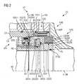
- the FIG. 2 shows an embodiment which is particularly suitable for high pressure application at differential pressures of over 200bar.
- the labyrinth sealing surface LSS is located on a substantially identical diameter as the fourth stationary seal SS4 between the rotor part RS and the rotating sealing element RSE.
- the difference between the fifth diameter DSS5 and the fourth diameter DSS4 is less than 10% of the fifth diameter DSS5.
- the difference between the third diameter DSS3 and the fourth diameter DSS4 is less than 10% of the fourth diameter DSS5.
Landscapes
- Engineering & Computer Science (AREA)
- General Engineering & Computer Science (AREA)
- Mechanical Engineering (AREA)
- Sealing Using Fluids, Sealing Without Contact, And Removal Of Oil (AREA)
- Structures Of Non-Positive Displacement Pumps (AREA)
Description
- Die Erfindung betrifft einen Wellendichtungseinsatz für eine Wellendichtung einer Turbomaschine, entsprechend dem Oberbegriff des Anspruchs 1.
- Trockengasdichtungen sind als Wellendichtungen in Turbomaschinen, beispielsweise in Turbokompressoren, zunehmend beliebt. Trockengasdichtungen im Sinne der vorliegenden Erfindung sind Wellendichtungen, die mindestens zwei sich um die Welle in Umfangsrichtung (bezogen auf die Rotationsachse) erstreckende Dichtelemente aufweisen, die jeweils mindestens eine zu dem gegenüberliegenden Dichtelement weisende Dichtfläche umfassen, mittels derer die Trockengasdichtung den Zwischenraum zwischen einem stationären Teil, beispielsweise einem Gehäuse und dem rotierenden Teil, insbesondere einer Welle, abdichtet. Eines der Dichtelemente rotiert mit dem rotierenden Teil und das andere Dichtelement ruht relativ zu dem Gehäuse. Mindestens eine der einander zugewendeten Dichtflächen weist Vorsprünge und/oder Ausnehmungen auf, welche in Zusammenwirkung mit einem Dichtgas für den Aufbau eines Gasfilms zwischen den beiden Dichtelementen an den Dichtflächen sorgen, so dass die Trockengasdichtung während der vorgesehenen Rotation berührungsfrei zwischen dem rotierenden Dichtelement und dem stehenden Dichtelement arbeitet. Die Trockengasdichtung erfordert ein sauberes Dichtungsgas, welches im Wesentlichen keine flüssigen Bestandteile aufweist um beschädigungsfrei bzw. berührungslos abzudichten. Die Ausnehmungen bzw. Vorsprünge können verschiedene Formen aufweisen und sind bevorzugt an nur einer Dichtungsfläche vorgesehen, bevorzugt an der Dichtungsfläche des rotierenden Dichtelementes. Ausnehmungen können U-förmig oder Tannenbaum-artig oder T-förmig oder in der Art einer Spirale ausgebildet sein, damit es zu einer Ausbildung eines stabilen Dichtungsfilmes des Dichtungsgases zwischen den beiden Dichtflächen kommt. Entscheidende Vorteile ergeben sich durch den Einsatz von Trockengasdichtungen beispielsweise an Verdichtern dadurch, dass die Leckage vergleichsweise gering ist und kein Schmieröl benötigt wird, wie beispielsweise bei Dichtungen, die mit Flüssigkeiten arbeiten oder im Vergleich zu einer Labyrinthdichtung. Regelmäßig werden Trockengasdichtungen auf einer Hochdruckseite mit einem Dichtungsgas beaufschlagt, wobei eine geringe Leckage dieses Dichtungsgases die Trockengasdichtung von der Hochdruckseite zu einer Seite niedrigeren Drucks - einer Niederdruckseite - passiert, wo in der Regel eine Ableitung dieser Leckage in eine sogenannte Vent-Leitung erfolgt. Auch um den Verbrauch an dem speziell aufbereiteten Dichtungsgas zu reduzieren, ist die Trockengasdichtung regelmäßig von anderen Wellendichtung umgeben, insbesondere auf der Hochdruckseite befindet sich regelmäßig eine Labyrinthdichtung, welche die Ausströmung des Dichtungsgases zu der von der Trockengasdichtung abgewendeten Seite hochdruckseitig reduziert. Der Hauptgrund für die serielle Zusatzdichtung, insbesondere Labyrinthdichtung, ist der Dichteffekt beim Versagen der Trockengasdichtung. Auch Trockengasdichtungen, die eine Dichtungsgasversorgung als zentrale Zuleitung der Dichtflächen aufweisen, sind in der Regel mittels einer seriellen Zusatzdichtung, insbesondere Labyrinthdichtung gegen Verunreinigung geschützt. Auf der Hochdruckseite der Trockengasdichtung ist in der Regel ein Prozessgas, das in dem Fall eines Turboverdichters unter einem Betriebsdruck steht. Das Dichtungsgas muss gegenüber diesem Prozessgas einen Überdruck aufweisen, um das potentiell verschmutzte Prozessgas von der empfindlichen Trockengasdichtung fern zu halten.
- Aus der gattungsgemäßen
DE 10 2009 012 038 A1 , derDE 42 25 642 C1 , derEP 0 781 948 A1 , derEP 1 207 310 A1 , derEP 1 914 387 A1 und derUS 6 325 382 B1 ist jeweils bereits eine Anordnung mit einer Trockengasdichtung und einer Labyrinthdichtung bekannt, bei der jedoch ein erhöhter Montageaufwand gegeben ist aufgrund der modularen Trennung der Labyrinthdichtung von der Trockengasdichtung. Die Fertigung und die Montage dieser beiden Module erfordert eine erhöhte Genauigkeit, weil Anforderungen an moderne Maschinenwirkungsgrade enge Radialspiele der Labyrinthdichtung und eine präzise Anordnung der Trockengasdichtung erfordern. - Ausgehend von dem beschriebenen Stand der Technik hat es sich die Erfindung zur Aufgabe gemacht, die Komplexität einer Turbomaschine, die einen Wellendichtungseinsatz der eingangs beschriebenen Art aufweist zu reduzieren, die Montage einer derartigen Turbomaschine zu vereinfachen und die Raumanforderung des Wellendichtungseinsatzes zu verringen.
- Eine Lösung für diese Aufgabe bietet die Erfindung mit einem Wellendichtungseinsatz der eingangs definierten Art mit den zusätzlichen Merkmalen des kennzeichnenden Teils des Anspruchs 1. Die Unteransprüche beinhalten vorteilhafte Weiterbildungen der Erfindung.
- In der Begriffswelt der Erfindung ist die Rotationsachse eine zentrale Achse des Wellendichtungseinsatzes, die als Rotationsachse bezeichnet ist, da es sich bei der Trockengasdichtung des Wellendichtungseinsatzes um eine Wellendichtung handelt, die naturgemäß eine in einem Betrieb rotierende Welle umgibt. Sämtliche ohne weitere Erläuterung auf die Begriffswelt einer Kreisbewegung bezogenen Angaben - beispielsweise axial, radial, Umfangsrichtung, Durchmesser - beziehen sich auf die Rotationsachse als Zentrum einer Kreisbewegung.
- Die Begriffswelt unterscheidet weiterhin zwei grundlegend verschiedene Dichtungstypen, nämlich die Wellendichtung, die zwei relativ zueinander in Bewegung befindliche Bauteile zueinander abdichtet und die stationäre Dichtung, welche zwei relativ zueinander in Ruhe befindliche Bauteile zueinander abdichtet.
- Mit Bezug auf die erfindungsgemäße Wellendichtung werden die Begriffe Hochdruckseite und Niederdruckseite benutzt, was daraufhin deutet, dass die Wellendichtung gegen eine Druckdifferenz ein Überströmen eines Fluides von einer Seite höherem Druckes auf eine Seite niedrigeren Druckes verhindert und dementsprechend die Druckdifferenz aufrecht erhält.
- Das bereits eingangs erwähnte Statorteil ist als stehendes Bauteil zu verstehen, welches Träger von Bauteilen zumindest der Trockengasdichtung des Wellendichtungseinsatzes ist. Das Statorteil ist derart ausgebildet, dass es in eine Ausnehmung eines Stators einsetzbar ist, welcher Stator bevorzugt als Gehäuse der Turbomaschine ausgebildet ist. Hierbei kann es sich auch um mit dem Gehäuse verbundene Bauteile handeln, so dass eine indirekte Verbindung des Statorteils mit einem Gehäuse einer Turbomaschine vorgesehen ist. Jedenfalls ist das Statorteil dazu geeignet, die Bauelemente des Wellendichtungseinsatzes in einer Einheit zusammenzufassen, so dass es sich bei dem Wellendichtungseinsatz um ein für sich bewegliches Modul handelt, das im Rahmen der Montage als Ganzes an der Welle eines Rotors anbringbar ist. Bevorzugt wird der erfindungsgemäße Wellendichtungseinsatz zunächst an der Welle angebracht und anschließend gemeinsam mit der Welle in beispielsweise ein Topfgehäuse eingelegt oder in eine untere Gehäusehälfte eingelegt und in dem Gehäuse befestigt.
- Der erfindungsgemäßen Ausbildung des stehenden Labyrinthdichtungsteils und des rotierenden Labyrinthdichtungsteils als Teile des Statorteils bzw. des Rotorteils ist derart zu verstehen, dass auch ein zumindest teilweise einstückige Ausbildung dieser jeweils beiden Bauelemente umfasst ist. Unter der erfindungsgemäßen festen Anbringung der Labyrinthdichtungsteile an den Hülsen ist eine lösbare Befestigung zu verstehen, welches insbesondere alternativ zu der zumindest teilweisen einstückigen Ausbildung vorgesehen werden kann.
- Besondere Vorteile ergeben sich durch den erfindungsgemäßen Wellendichtungseinsatz aufgrund der Reduktion der Komplexität in Folge der Verringerung der Teileanzahl einer Turbomaschine, da die an die Trockengasdichtung des Wellendichtungseinsatzes angrenzende Labyrinthdichtung nunmehr Bestandteil des Wellendichtungseinsatzes ist.
- Besonders vorteilhaft ist die Erfindung für die Montage eines Topfverdichters (Barrel-Type-Casing), weil dort die Dichtungen mit der Welle gemeinsam in das Gehäuse eingelassen werden.
- Der Vorteil des Vereinfachung ist auch im Rahmen der Montage signifikant, da die komplexen Ausrichtarbeiten eines Rotors zu dem Wellendichtungseinsatz und dem herkömmlich von diesem getrennt angeordneten Labyrinthdichtungseinsatz stark vereinfacht werden bzw. entfallen. Im Stand der Technik mussten schwierige und zeitaufwändige Ausrichtungen stattfinden, insbesondere der Bauteile Rotor, Trockengasdichtung, Labyrinthdichtung bzw. Gehäuse zueinander. Aufgrund der Kombination der Labyrinthdichtung mit der Trockengasdichtung in dem erfindungsgemäßen Wellendichtungseinsatz ist es darüber hinaus möglich, erfindungsgemäß den Bauraum einer Wellendichtung einer Turbomaschine zu verringern, insbesondere, weil die Labyrinthdichtung nicht mehr eine eigene Befestigung an dem Gehäuse erfordert, sondern diese mit dem Wellendichtungseinsatz direkt an dem Gehäuse befestigt ist. Dieses Bauraumersparnis führt insbesondere zu einem geringeren axialen Bauraumbedarf, welche Verringerung eine Reduktion der erforderlichen Länge der Welle des Rotors ermöglicht, wodurch sich entscheidende rotordynamische Vorteile ergeben, insbesondere Schwingungsamplituden geringer ausfallen und sich etwaige Resonanzfrequenzen in Folge der Versteifung vorteilhaft erhöhen. Bei ansonsten gleichen Betriebsparametern einer Turbomaschine ermöglicht dies eine Verringerung des Wellendurchmessers, so dass bei angenommenen gleichen Radialspielbedarf eine kleinere Fläche durch die Wellendichtung abzudichten ist, so dass eine nur geringere potentielle Leckagemenge entsteht und sich der Wirkungsgrad der Turbomaschine erhöht.
- Sinnvoll ist die Anordnung der Labyrinthdichtung auf der Hochdruckseite als die axial äußerste Wellendichtung, so dass gewährleistet ist, dass keine Verunreinigungen von der Hochdruckseite ungehindert zur Trockengasdichtung des Wellendichtungseinsatzes gelangen können. Sinnvoll ist der Wellendichtungseinsatz an dem Statorteil mit einer zweiten stationären Dichtung versehen, so dass das Statorteil dichtend in einer Ausnehmung des Stators einsetzbar ist. Weiterhin ist zweckmäßig das Rotorteil mit einer stationären Dichtung versehen, so dass das Rotorteil dichtend auf die Welle eines Rotors anbringbar ist. Vorteilhaft kann die Welle des Rotors mit einem Absatz versehen sein, an dem das Rotorteil mit einer Kontaktfläche zur axialen Anlagen kommt. Bevorzugt handelt es sich bei den stationären Dichtungen zwischen der Welle und dem Rotorteil bzw. zwischen der Statorausnehmung und dem Statorteil um Dichtungen mit einem V-förmigen Querschnitt, welcher sich unter einer Druckdifferenz derart aufweitet, dass die Dichtwirkung unterstützt wird. Dieser Dichtungstyp wird als "PTFE Cup seal" und weist gute Widerstandsfähigkeiten auch gegen Druckschläge auf. Andere Dichtungen können auch verwendet werden, zum Beispiel elastomere O-Ring-Dichtungen.
- Die Erfindung bezieht sich nicht nur auf einen Wellendichtungseinsatz, sondern auch auf eine Turbomaschine umfassend den Wellendichtungseinsatz, zumindest ein Gehäuse und einen Rotor mit einer Welle bzw. um eine Anordnung eines Wellendichtungseinsatzes der erfindungsgemäßen Art mit einem Rotor umfassend eine Welle und einen Stator, der den Rotor zumindest teilweise umgibt.
- Besonders platzsparend ist eine Weiterbildung der erfindungsgemäßen Trockengasdichtung, bei der eine sich in Umfangsrichtung und Axialrichtung erstreckende Dichtfläche zwischen dem stehenden Labyrinthdichtungsteil und dem rotierenden Labyrinthdichtungsteil auf einem fünften Durchmesser koaxial zur Rotationsachse angeordnet ist, wobei der äußerste Durchmesser der Dichtflächen der Trockengasdichtung kleiner ist als der fünfte Durchmesser.
- Eine derartige Weiterbildung wird bevorzugt bei Turbomaschinen eingesetzt, deren Geometrie und Betriebsparameter ansonsten, bei einem Versagen der Trockengasdichtung, eine für das Axiallager noch erträgliche Veränderung des Schubes auf den Rotor hervorruft.
- Alternativ zu der zuvor erläuterten vorteilhaften Weiterbildung ist es zweckmäßig, wenn die sich in Umfangsrichtung und Axialrichtung erstreckende Dichtfläche zwischen dem stehenden Labyrinthdichtungsteil und dem rotierenden Labyrinthdichtungsteil auf dem fünften Durchmesser koaxial zur Rotationsachse im Wesentlichen identisch ist mit einem vierten Durchmesser, auf dem sich eine vierte stationäre Dichtung zwischen der Statorteil und dem stehenden Dichtelement der Trockengasdichtung befindet. Bevorzugt ist die Differenz zwischen dem vierten Durchmesser und dem fünften Durchmesser geringer als 10% des fünften Durchmessers. Auf diese Weise findet eine nur verhältnismäßig geringe Veränderung des Schubes auf eine Welle einer Turbomaschine statt, im Falle eines Defektes der Trockengasdichtung des erfindungsgemäßen Wellendichtungseinsatzes, da die Durchmesser, an denen die unterschiedlichen Drücke, die sich durch den Differenzdruck über die Trockengasdichtung unterscheiden, an dem Rotor anliegen bei einem Abbau über die Trockengasdichtung selbst nicht unterscheiden, zu dem Fall, dass der Differenzdruck über die angeschlossene Labyrinthdichtung abgebaut wird. Insbesondere bei einem Verdichter mit einer beabsichtigen Betriebsweise bei der die Trockengasdichtung eine Druckdifferenz von insbesondere über 200bar, abbaut im Normalbetriebszustand ist ein Axiallager in der Regel nicht in der Lage, die Schubveränderung zu ertragen, wenn die Trockengasdichtung einen Defekt hat und sich daraus eine Veränderung des Wellenschubes ergibt, sollte nicht das vorhergehend definierte Kriterium hinsichtlich der Durchmesser erfüllt sein.
- Damit die Dichtelemente der Trockengasdichtung des Wellendichtungseinsatzes keine unnötig hohen Belastungen erfahren, die die erforderliche Geometrie für den Aufbau des die Berührungslosigkeit herstellenden Schmierfilms zwischen den Dichtflächen gewährleisten, ist es sinnvoll, wenn eine zweite stationäre Dichtung zwischen dem Rotorteil und dem stehenden Dichtelement auf einem dritten Durchmesser angeordnet ist und der dritte Durchmesser sich von dem vierten Durchmesser um nicht mehr als 10% des vierten Durchmessers unterscheidet.
- Zweckmäßig weist eine vorteilhafte Weiterbildung der Erfindung eine Zuleitung eines Dichtungsgases zwischen der Labyrinthdichtung und der Trockengasdichtung des Wellendichtungseinsatzes in den axialen Zwischenraum auf, so dass die Labyrinthdichtung einen Austritt des aufbereiteten und reinen Dichtungsgases in Richtung der Hochdruckseite reduziert und die Trockengasdichtung nur mit dem reinen Dichtungsgas beaufschlagt wird. Zweckmäßig ist hierzu das Dichtungsgas gegenüber einem Prozessgas jenseitig der Labyrinthdichtung auf der Hochdruckseite in einem Überdruck, so dass kein Anteil des Prozessgases die Trockengasdichtung erreichen kann. Auf der Niederdruckseite der Trockengasdichtung ist zweckmäßig eine Dichtungsableitung vorgesehen, welche das reine Dichtungsgas ggf. als Gemisch mit einem auf der Niederdruckseite anstehenden anderen Gas einer Dichtungsgasaufbereitung zuleitet oder einer Abfackelung zuleitet.
- Im Folgenden ist die Erfindung anhand von Ausführungsbeispielen unter Bezugnahme auf Zeichnungen näher erläutert, wobei sich dem Fachmann aus insbesondere beliebiger Kombination der Ansprüche von den Ausführungsbeispielen abweichende Möglichkeiten der Ausführung der Erfindung ergeben. Es zeigen:
-
Figur 1 einen Längsschnitt durch einen erfindungsgemäßen Wellendichtungseinsatz bevorzugt für Differenzdrücke unter 200bar und -
Figur 2 einen Längsschnitt durch einen erfindungsgemäßen Wellendichtungseinsatz bevorzugt für Differenzdrücke über 200bar. - In der folgenden Beschreibung sind identische Bauelemente oder Bauelemente mit identischen Funktionen mit gleichem Bezugszeichen versehen. Ausdrücke, wie axial, radial, Umfangsrichtung, Durchmesser und Radius beziehen sich auf eine Rotationsachse AX, welche eine zentrale Achse eines erfindungsgemäßen Wellendichtungseinsatzes DGSM ist. Die in den
Figuren 1 und2 dargestellte Wellendichtungseinsatz DGSM umfasst ein Statorteil CS und ein Rotorteil RS sowie eine Trockengasdichtung DGS und eine Labyrinthdichtung LS. Das Rotorteil RS des Wellendichtungseinsatzes DGSM ist mittels einer zweiten statischen Dichtung STS2 auf einer Welle SH eines Rotors R dichtend angebracht. Die Welle SH ist gleichfalls Trägerin mindestens eines Laufrades einer Turbomaschine CO, die in nicht näher dargestellter Weise als Zentrifugalverdichter ausgebildet ist. - Das Statorteil CS ist mittels einer ersten stationären Dichtung STS1 dichtend in eine Statorausnehmung CR eingesetzt. Die erste stationäre Dichtung STS1 und die zweite stationäre Dichtung STS2 weisen ein V-Profil auf, welches in einer jeweiligen sich in Umfangsrichtung erstreckenden Dichtungsnut derart angeordnet ist, dass sich das V-Profil aufweitet, wenn von einer Hochdruckseite HPS eine Druckbeaufschlagung der stationären Dichtung erfolgt. Der Wellendichtungseinsatz DGSM weist eine Hochdruckseite HPS und eine Niederdruckseite LPS auf, wobei die Hochdruckseite HPS einem gegenüber der Niederdruckseite LPS unter Überdruck stehenden Prozessgas ausgesetzt ist. Das Statorteil ist gegenüber der Statorausnehmung CR zusätzlich mit einer statischen Dichtung STS11 abgedichtet. Der Wellendichtungseinsatz DGSM ist in den
Figuren 1 ,2 Bestandteil einer nicht in Gänze dargestellten Wellendichtung SHS. - Ein Zwischenraum IR zwischen dem Statorteil CS und dem Rotorteil RS ist mittels der Trockengasdichtung DGS einerseits und in serieller Anordnung dazu mit der Labyrinthdichtung LS andererseits abgedichtet. Die Trockengasdichtung DGS dient hierbei dem Abbau der Druckdifferenz DGS zwischen der Hochdruckseite HPS und der Niederdruckseite LPS. Zwischen der Trockengasdichtung DGS und der Labyrinthdichtung LS ist eine Dichtungsgaszuleitung SGS eines besonders reinen Dichtungsgases SG vorgesehen. Die Funktion der Labyrinthdichtung LS ist hierbei die Reduktion des Austrittes des Dichtungsgases SG in Richtung der Hochdruckseite bzw. in das potentiell verunreinigte und aggressive Prozessgas PG. Die Trockengasdichtung DGS wird daher hochdruckseitig nur mit dem sauberen und trockenen Dichtungsgas SG beaufschlagt, welches gegenüber dem Prozessgas PG einen Überdruck aufweist. Auf der Niederdruckseite LPS der Trockengasdichtung DGS ist eine Dichtungsableitung SGE der nur geringen Leckage der Trockengasdichtung DGS vorgesehen, welche in einen Vent oder eine Abfackelung bevorzugt mündet.
- Die Trockengasdichtung DGS weist ein rotierendes Dichtelement RSE und ein stehendes Dichtelement SSE auf, die sich mit einer jeweiligen Dichtoberfläche an einer gemeinsamen Trockengasdichtungsdichtfläche DGSSS gegenüberstehen. Das rotierende Dichtelement RSE ist gegenüber dem Rotorteil RS mittels einer dritten stationären Dichtung SS3, die sich auf einem dritten Durchmesser DSS3 in Umfangsrichtung erstreckt, gegenüber dem Differenzdruck abgedichtet. Das Statorteil CS weist ein elastisches Element EE auf, welches mittels eines Kolbens PT das stehende Dichtelement SSE gegen das rotierende Dichtelement RSE vorspannt. Das stehende Dichtelement SSE ist gegenüber dem Führungsring GD mittels einer vierten stationären Dichtung SS4 auf einem vierten Durchmesser DSS4 gegen den Differenzdruck abgedichtet. In der Begriffswelt der Erfindung zählen das elastische Element EE und der Kolben PT sowie eine Führung GD zu dem Statorteil CS hinzu.
- Die Labyrinthdichtung LS weist ein stehendes Labyrinthdichtungsteil SLSM und ein rotierendes Labyrinthdichtungsteil RLSM auf, die sich an einer sich axial und in Umfangsrichtung erstreckenden mittleren Labyrinthdichtungsfläche LSS einander gegenüber stehen, wobei sich die Labyrinthdichtungsfläche LSS in Umfangsrichtung auf einem fünften Durchmesser DSS5 erstreckt.
- Unter der mittleren Labyrinthdichtungsfläche ist eine Fläche zu verstehen, welche sich axial und in Umfangsrichtung entlang des fünften Durchmessers DSS5 erstreckt, wobei der fünfte Durchmesser das Ergebnis einer Kreisflächen-gewichteten Mittelung ist von dem hochdruckseitigen äußeren Durchmesser, dem hochdruckseitigen inneren Durchmesser, dem niederdruckseitigen äußeren Durchmesser, dem niederdruckseitigen inneren Durchmesser der Öffnung der Labyrinthdichtung LS.
- Das rotierende Dichtelement RSE steht dem stehenden Dichtelement SSE an der Trockengasdichtungsfläche DGSSS mit einer rotierenden Dichtfläche DGSRS gegenüber, welche mit Vorsprüngen und Ausnehmungen versehen ist, die bevorzugt keilförmig und/oder spiralförmig sind. Das stehende Dichtelement SSE weist an einer stehenden Dichtungsfläche DGSTS, die der Trockengasdichtungsdichtfläche DGSS zugewendet ist eine speziell ausgebildete Oberfläche auf. Die Ausbildung der Oberfläche ist der gegenüberliegenden rotierenden Dichtfläche DGSRS derart angepasst, dass ein berührungsloser Betrieb der Trockengasdichtung DGS unter Ausbildung eines entsprechenden Schmierfilms des Dichtungsgases SG gewährleistet ist.
- Die
Figur 1 zeigt eine besonders platzsparende Ausbildung des Wellendichtungseinsatzes DGSM, bei dem der fünfte Durchmesser DSS5 größer ist als ein äußerster Außendurchmesser der Dichtflächen DGSOD der Trockengasdichtung DGS, so dass eine axiale Überlappung zumindest teilweise zwischen der Labyrinthdichtung LS und Bauteilen der Trockengasdichtung DGS möglich ist. Im konkreten Beispiel derFigur 1 überschneidet sich die Labyrinthdichtung LS axial mit dem rotierenden Dichtelement RSE der Trockengasdichtung DGS. - Die
Figur 2 zeigt eine Ausbildung, welche insbesondere für die Hochdruckanwendung bei Differenzdrücken von über 200bar geeignet ist. Hier befindet sich die Labyrinthdichtungsfläche LSS auf einem im Wesentlichen identischen Durchmesser, wie die vierte stationäre Dichtung SS4 zwischen dem Rotorteil RS und dem rotierenden Dichtelement RSE. Die Differenz zwischen dem fünften Durchmesser DSS5 und dem vierten Durchmesser DSS4 ist kleiner als 10% des fünften Durchmessers DSS5. Weiterhin ist zur Minimierung von mechanischer Belastung auf die Dichtelemente der Trockengasdichtung DGS die Differenz zwischen dem dritten Durchmesser DSS3 und dem vierten Durchmesser DSS4 geringer als 10% von dem vierten Durchmesser DSS5.
Claims (4)
- Wellendichtungseinsatz (DGSM) für eine Wellendichtung (SHS) einer Turbomaschine (CO), die sich in einer axialen Richtung entlang einer Rotationsachse (AX) erstreckt, umfassend- ein Rotorteil (RS), das derart ausgebildet ist, dass es auf einer Welle (SH) eines sich entlang der Rotationsachse (AX) erstreckenden Rotors (R) anbringbar ist,- ein Statorteil (CS), das derart ausgebildet ist, dass es in eine Statorausnehmung (CR) einsetzbar ist,- umfassend mindestens eine Trockengasdichtung (DGS), welche ein an dem Rotorteil (RS) angebrachtes rotierendes Dichtelement (RSE) und ein an dem Statorteil (CS) angebrachtes stehendes Dichtelement (SSE) aufweist zum Abdichten eines Zwischenraums (IR) zwischen dem rotierenden Dichtelement (RSE) und dem stehenden Dichtelement (SSE), wobei das stehende Dichtelement (SSE) und das rotierende Dichtelement (RSE) an einer sich radial und in Umfangsrichtung erstreckenden Dichtfläche einander gegenüberliegend angeordnet sind, wobei der Wellendichtungseinsatz (DGSM) an einem axialen Ende eine Hochdruckseite (HPS) und an dem anderen axialen Ende eine Niederdruckseite (LPS) aufweist,
wobei auf der Hochdruckseite (HPS) eine Labyrinthdichtung (LS) zur Abdichtung des Zwischenraums (IR) in serieller Anordnung zu der Trockengasdichtung (DGS) vorgesehen ist,
wobei die Labyrinthdichtung (LSS) die axial äußerste Dichtung des Wellendichtungseinsatzes (DGSM) auf der Hochdruckseite (HPS) ist,
wobei das Statorteil (CS), mit einer ersten stationären Dichtung (STS1) auf einem ersten Dichtungsdurchmesser (DSS1) derart ausgebildet ist, dass das Statorteil (CS) in die Statorausnehmung (CR) dichtend einsetzbar ist und das Rotorteil (RS), mit einer zweiten stationären Dichtung (STS2) auf einem zweiten Dichtungsdurchmesser (DSS2) derart ausgebildet ist, dass es auf der Welle (SH) dichtend anbringbar ist
dadurch gekennzeichnet, dass die Labyrinthdichtung (LSS) einen stehenden Labyrinthdichtungsteil (SLSM) und einen rotierenden Labyrinthdichtungsteil (RLSM) umfasst, wobei der stehende Labyrinthdichtungsteil (SLSM) ein Teil des Statorteils (CS) ist oder an diesem fest angebracht ist und
wobei der rotierende Labyrinthdichtungsteil (RLSM) ein Teil des Rotorteils (RS) ist oder an diesem fest angebracht ist. - Wellendichtungseinsatz (DGSM) nach Anspruch 1,
wobei eine sich in Umfangsrichtung und Axialrichtung erstreckende mittlere Labyrinthdichtungsfläche (LSS) zwischen den stehenden Labyrinthdichtungsteil (SLSM) und dem rotierenden Labyrinthdichtungsteil (RLSM) auf einem fünften Durchmesser (DSS5) koaxial zur Rotationsachse (AX) angeordnet ist, wobei der äußerste Durchmesser der Dichtflächen (DGSOD) der Trockengasdichtung (DGS) kleiner ist als der fünfte Durchmesser (DSS5). - Wellendichtungseinsatz (DGSM) nach Anspruch 1,
wobei
eine sich in Umfangsrichtung und Axialrichtung erstreckende mittlere Labyrinthdichtungsfläche (LSS) zwischen dem stehenden Labyrinthdichtungsteil (SLSM) und dem rotierenden Labyrinthdichtungsteil (RLSM) auf einem fünften Durchmesser (DSS5) koaxial zur Rotationsachse (AX) angeordnet ist und
zwischen dem stehenden Dichtelement (SSE) und der Statorteil (CS) eine vierte stationäre Dichtung (SS4) auf einem vierten Durchmesser (DSS4) angeordnet ist,
dadurch gekennzeichnet, dass
der Betrag der Differenz zwischen dem vierten Durchmesser (DSS4) und dem fünften Durchmesser (DSS5) geringer als 10% des fünften Durchmessers ist (DSS5). - Wellendichtungseinsatz (DGSM) nach einem der Ansprüche 1 bis 3,
wobei der Zwischenraum (IR) axial zwischen der Labyrinthdichtung (LS) und der Trockengasdichtung (DGS) eine Dichtungsgaszuleitung (SGS) aufweist zur Zuleitung eines Dichtungsgases (SG) zwischen die Labyrinthdichtung (LS) und die Trockengasdichtung (DGS),
wobei der Wellendichtungseinsatz (DGSM)auf der der Niederdruckseite (LPS) zugewendeten Seite der Trockengasdichtung (DGS) eine Dichtungsgasableitung (SGE) aufweist zur Ableitung von Dichtungsgas (SG), welches die Trockengasdichtung (DGS) passiert hat.
Applications Claiming Priority (2)
| Application Number | Priority Date | Filing Date | Title |
|---|---|---|---|
| DE102011007071A DE102011007071A1 (de) | 2011-04-08 | 2011-04-08 | Wellendichtungseinsatz |
| PCT/EP2012/055273 WO2012136496A1 (de) | 2011-04-08 | 2012-03-26 | Wellendichtungseinsatz |
Publications (2)
| Publication Number | Publication Date |
|---|---|
| EP2663791A1 EP2663791A1 (de) | 2013-11-20 |
| EP2663791B1 true EP2663791B1 (de) | 2015-08-26 |
Family
ID=45952488
Family Applications (1)
| Application Number | Title | Priority Date | Filing Date |
|---|---|---|---|
| EP12713650.5A Revoked EP2663791B1 (de) | 2011-04-08 | 2012-03-26 | Wellendichtungseinsatz |
Country Status (6)
| Country | Link |
|---|---|
| US (1) | US9518473B2 (de) |
| EP (1) | EP2663791B1 (de) |
| CN (1) | CN103459903B (de) |
| DE (1) | DE102011007071A1 (de) |
| RU (1) | RU2589415C2 (de) |
| WO (1) | WO2012136496A1 (de) |
Families Citing this family (16)
| Publication number | Priority date | Publication date | Assignee | Title |
|---|---|---|---|---|
| DE102012223830A1 (de) * | 2012-12-19 | 2014-06-26 | Siemens Aktiengesellschaft | Abdichtung eines Verdichterrotors |
| FR3000167B1 (fr) | 2012-12-20 | 2015-08-21 | Cryostar Sas | Ensemble joint d'etancheite a gaz pour pompes a liquide cryogenique |
| DE102013227208A1 (de) * | 2013-12-30 | 2015-07-02 | Siemens Aktiengesellschaft | Dichtsystem für eine Dampfturbine sowie Dampfturbine |
| EP2918846A1 (de) | 2014-03-14 | 2015-09-16 | Siemens Aktiengesellschaft | Wellendichtungsanordnung |
| FI127009B (fi) * | 2014-03-27 | 2017-09-15 | Andritz Oy | Lipeäsuodin ja menetelmä lipeäsuotimen yhteydessä |
| DE102014011042A1 (de) * | 2014-07-26 | 2016-01-28 | Man Diesel & Turbo Se | Strömungsmaschine |
| CN106014509A (zh) * | 2016-07-28 | 2016-10-12 | 中国核动力研究设计院 | 一种以超临界二氧化碳为工质的透平发电机组 |
| EP3293426A1 (de) * | 2016-09-13 | 2018-03-14 | Siemens Aktiengesellschaft | Gasdichtung |
| EP3293425A1 (de) * | 2016-09-13 | 2018-03-14 | Siemens Aktiengesellschaft | Gasdichtung |
| IT201700029982A1 (it) * | 2017-03-17 | 2018-09-17 | Nuovo Pignone Tecnologie Srl | Tenuta a gas |
| DE102017109663A1 (de) * | 2017-05-05 | 2018-11-08 | Man Diesel & Turbo Se | Dichtungssystem, Strömungsmaschine mit einem Dichtungssystem und Verfahren zum Reinigen desselben |
| DE102017223791A1 (de) | 2017-12-27 | 2019-06-27 | Siemens Aktiengesellschaft | Wellendichtungsanordnung einer Turbomaschine, Turbomaschine |
| DE102018202681B3 (de) * | 2018-02-22 | 2019-07-04 | Eagleburgmann Germany Gmbh & Co. Kg | Gleitringdichtungsanordnung mit geteilter Wellenhülse |
| EP3862598B1 (de) * | 2020-02-07 | 2023-05-24 | Dresser-Rand SAS | Wellendichtungsanordnung |
| US11692628B2 (en) * | 2020-10-26 | 2023-07-04 | Changshu Institute Of Technology | Sealing device for gas-liquid two-phase fluid medium under variable working conditions |
| US11572952B2 (en) | 2021-05-29 | 2023-02-07 | Dresser-Rand SAS | Shaft sealing arrangement |
Citations (8)
| Publication number | Priority date | Publication date | Assignee | Title |
|---|---|---|---|---|
| WO1992019869A1 (en) | 1991-04-30 | 1992-11-12 | Nova Corporation Of Alberta | Co-planar seal arrangement |
| DE4225642C1 (de) | 1992-07-02 | 1993-07-29 | Sulzer-Escher Wyss Ag, Zuerich, Ch | |
| EP0781948A1 (de) | 1995-12-29 | 1997-07-02 | Sulzer Turbo AG | Turbomaschine für nicht ideale Prozessgase |
| US6325382B1 (en) * | 1999-05-21 | 2001-12-04 | Nippon Pillar Packing Co., Ltd. | Non-contact type mechanical seal |
| EP1207310A1 (de) * | 1999-07-23 | 2002-05-22 | Hitachi, Ltd. | Turbomaschine und gleitringdichtung für diese maschine |
| JP2004308754A (ja) | 2003-04-04 | 2004-11-04 | Mitsubishi Heavy Ind Ltd | 軸封装置 |
| EP1914387A1 (de) * | 2006-10-19 | 2008-04-23 | Siemens Aktiengesellschaft | Turbomaschine und Verfahren zum Turnen einer Turbomaschine |
| DE102009012038A1 (de) | 2009-03-10 | 2010-09-16 | Siemens Aktiengesellschaft | Wellendichtung für eine Strömungsmaschine |
Family Cites Families (7)
| Publication number | Priority date | Publication date | Assignee | Title |
|---|---|---|---|---|
| RU2004867C1 (ru) * | 1990-05-21 | 1993-12-15 | Zakharov Boris S | Уплотнительное устройство вращающихс валов гидромашин |
| US5066026A (en) * | 1990-06-11 | 1991-11-19 | Kaydon Corporation | Gas face seal |
| US5718560A (en) * | 1995-12-29 | 1998-02-17 | Sulzer Turbo Ag | Turbocompressor for non-ideal process gases |
| US6109617A (en) * | 1998-03-04 | 2000-08-29 | Power Packing Co., Inc. | Gas seal assembly and method of sealing |
| US7854584B2 (en) * | 2007-05-24 | 2010-12-21 | General Electric Company | Barrier sealing system for centrifugal compressors |
| WO2009143213A2 (en) * | 2008-05-21 | 2009-11-26 | John Crane Inc. | Seal monitoring and control system |
| CN101526135A (zh) * | 2009-04-17 | 2009-09-09 | 丹东克隆集团有限责任公司 | 迷宫复合式机械密封装置 |
-
2011
- 2011-04-08 DE DE102011007071A patent/DE102011007071A1/de not_active Ceased
-
2012
- 2012-03-26 WO PCT/EP2012/055273 patent/WO2012136496A1/de not_active Ceased
- 2012-03-26 EP EP12713650.5A patent/EP2663791B1/de not_active Revoked
- 2012-03-26 CN CN201280017305.2A patent/CN103459903B/zh not_active Expired - Fee Related
- 2012-03-26 US US14/110,198 patent/US9518473B2/en not_active Expired - Fee Related
- 2012-03-26 RU RU2013149860/06A patent/RU2589415C2/ru not_active IP Right Cessation
Patent Citations (8)
| Publication number | Priority date | Publication date | Assignee | Title |
|---|---|---|---|---|
| WO1992019869A1 (en) | 1991-04-30 | 1992-11-12 | Nova Corporation Of Alberta | Co-planar seal arrangement |
| DE4225642C1 (de) | 1992-07-02 | 1993-07-29 | Sulzer-Escher Wyss Ag, Zuerich, Ch | |
| EP0781948A1 (de) | 1995-12-29 | 1997-07-02 | Sulzer Turbo AG | Turbomaschine für nicht ideale Prozessgase |
| US6325382B1 (en) * | 1999-05-21 | 2001-12-04 | Nippon Pillar Packing Co., Ltd. | Non-contact type mechanical seal |
| EP1207310A1 (de) * | 1999-07-23 | 2002-05-22 | Hitachi, Ltd. | Turbomaschine und gleitringdichtung für diese maschine |
| JP2004308754A (ja) | 2003-04-04 | 2004-11-04 | Mitsubishi Heavy Ind Ltd | 軸封装置 |
| EP1914387A1 (de) * | 2006-10-19 | 2008-04-23 | Siemens Aktiengesellschaft | Turbomaschine und Verfahren zum Turnen einer Turbomaschine |
| DE102009012038A1 (de) | 2009-03-10 | 2010-09-16 | Siemens Aktiengesellschaft | Wellendichtung für eine Strömungsmaschine |
Also Published As
| Publication number | Publication date |
|---|---|
| DE102011007071A1 (de) | 2012-10-11 |
| US20140030063A1 (en) | 2014-01-30 |
| CN103459903A (zh) | 2013-12-18 |
| EP2663791A1 (de) | 2013-11-20 |
| RU2013149860A (ru) | 2015-05-20 |
| WO2012136496A1 (de) | 2012-10-11 |
| CN103459903B (zh) | 2015-12-23 |
| US9518473B2 (en) | 2016-12-13 |
| RU2589415C2 (ru) | 2016-07-10 |
Similar Documents
| Publication | Publication Date | Title |
|---|---|---|
| DE102011007071A1 (de) | Wellendichtungseinsatz | |
| EP2665953B1 (de) | Wellendichtungsanordnung | |
| DE60300288T2 (de) | Abgedichtetes ölgedämpftes Wälzlager | |
| DE112013001944B4 (de) | Regelklappenanordnung eines Abgasturboladers | |
| EP2466149A1 (de) | Strömungsmaschine für ein Fluid mit einem radialen Dichtspalt und einem stationären Verschleissring | |
| EP3032148B1 (de) | Axialer wellendichtring | |
| EP3699405B1 (de) | Lagergehäuse und ein abgasturbolader mit einem solchen gehäuse | |
| DE112013002424T5 (de) | Abgasturbolader | |
| DE60207675T2 (de) | Gleitringdichtung | |
| WO2009156260A1 (de) | Kassettendichtung | |
| WO2008015060A1 (de) | Pumpenantrieb eines automatgetriebes | |
| EP3203035B1 (de) | Leitschaufelsystem für eine strömungsmaschine | |
| DE102015106610A1 (de) | Pumpenvorrichtung | |
| EP2707629B1 (de) | Vorrichtung zum abdichten eines pumpraums einer drehkolbenpumpe, sowie drehkolbenpumpe mit selbiger | |
| DE102013208357B3 (de) | Anordnung mit einer Dichtung | |
| DE102016217286A1 (de) | Druckbehälter | |
| EP0991884A1 (de) | Gleitringdichtung für kurbelwelle | |
| DE102017100540A1 (de) | Exzenterschneckenpumpe | |
| DE102015221255A1 (de) | Anordnung zur Wellendichtung | |
| EP2994616B1 (de) | Anstreifdichtung und dichtungsanordnung | |
| DE102014118702A1 (de) | Kurbelwelle und Kurbelwellenanordnung | |
| EP4239229B1 (de) | Axialdichtring | |
| DE202018103845U1 (de) | Pumpenvorrichtung | |
| EP2218947A1 (de) | Rotor für eine Strömungsmaschine mit einer Wellendichtung und Verfahren zur Reparatur des Rotors | |
| DE102021132683A1 (de) | Dichtungsanordnung für einen Wellendichtring und Verfahren zu dessen Herstellung |
Legal Events
| Date | Code | Title | Description |
|---|---|---|---|
| PUAI | Public reference made under article 153(3) epc to a published international application that has entered the european phase |
Free format text: ORIGINAL CODE: 0009012 |
|
| 17P | Request for examination filed |
Effective date: 20130816 |
|
| AK | Designated contracting states |
Kind code of ref document: A1 Designated state(s): AL AT BE BG CH CY CZ DE DK EE ES FI FR GB GR HR HU IE IS IT LI LT LU LV MC MK MT NL NO PL PT RO RS SE SI SK SM TR |
|
| DAX | Request for extension of the european patent (deleted) | ||
| 17Q | First examination report despatched |
Effective date: 20140624 |
|
| GRAP | Despatch of communication of intention to grant a patent |
Free format text: ORIGINAL CODE: EPIDOSNIGR1 |
|
| INTG | Intention to grant announced |
Effective date: 20150402 |
|
| GRAS | Grant fee paid |
Free format text: ORIGINAL CODE: EPIDOSNIGR3 |
|
| GRAA | (expected) grant |
Free format text: ORIGINAL CODE: 0009210 |
|
| AK | Designated contracting states |
Kind code of ref document: B1 Designated state(s): AL AT BE BG CH CY CZ DE DK EE ES FI FR GB GR HR HU IE IS IT LI LT LU LV MC MK MT NL NO PL PT RO RS SE SI SK SM TR |
|
| REG | Reference to a national code |
Ref country code: GB Ref legal event code: FG4D Free format text: NOT ENGLISH |
|
| REG | Reference to a national code |
Ref country code: CH Ref legal event code: EP |
|
| REG | Reference to a national code |
Ref country code: AT Ref legal event code: REF Ref document number: 745380 Country of ref document: AT Kind code of ref document: T Effective date: 20150915 |
|
| REG | Reference to a national code |
Ref country code: IE Ref legal event code: FG4D Free format text: LANGUAGE OF EP DOCUMENT: GERMAN |
|
| REG | Reference to a national code |
Ref country code: DE Ref legal event code: R096 Ref document number: 502012004296 Country of ref document: DE |
|
| REG | Reference to a national code |
Ref country code: NL Ref legal event code: FP |
|
| REG | Reference to a national code |
Ref country code: LT Ref legal event code: MG4D |
|
| PG25 | Lapsed in a contracting state [announced via postgrant information from national office to epo] |
Ref country code: GR Free format text: LAPSE BECAUSE OF FAILURE TO SUBMIT A TRANSLATION OF THE DESCRIPTION OR TO PAY THE FEE WITHIN THE PRESCRIBED TIME-LIMIT Effective date: 20151127 Ref country code: LT Free format text: LAPSE BECAUSE OF FAILURE TO SUBMIT A TRANSLATION OF THE DESCRIPTION OR TO PAY THE FEE WITHIN THE PRESCRIBED TIME-LIMIT Effective date: 20150826 Ref country code: NO Free format text: LAPSE BECAUSE OF FAILURE TO SUBMIT A TRANSLATION OF THE DESCRIPTION OR TO PAY THE FEE WITHIN THE PRESCRIBED TIME-LIMIT Effective date: 20151126 Ref country code: FI Free format text: LAPSE BECAUSE OF FAILURE TO SUBMIT A TRANSLATION OF THE DESCRIPTION OR TO PAY THE FEE WITHIN THE PRESCRIBED TIME-LIMIT Effective date: 20150826 Ref country code: LV Free format text: LAPSE BECAUSE OF FAILURE TO SUBMIT A TRANSLATION OF THE DESCRIPTION OR TO PAY THE FEE WITHIN THE PRESCRIBED TIME-LIMIT Effective date: 20150826 |
|
| PG25 | Lapsed in a contracting state [announced via postgrant information from national office to epo] |
Ref country code: ES Free format text: LAPSE BECAUSE OF FAILURE TO SUBMIT A TRANSLATION OF THE DESCRIPTION OR TO PAY THE FEE WITHIN THE PRESCRIBED TIME-LIMIT Effective date: 20150826 Ref country code: SE Free format text: LAPSE BECAUSE OF FAILURE TO SUBMIT A TRANSLATION OF THE DESCRIPTION OR TO PAY THE FEE WITHIN THE PRESCRIBED TIME-LIMIT Effective date: 20150826 Ref country code: PT Free format text: LAPSE BECAUSE OF FAILURE TO SUBMIT A TRANSLATION OF THE DESCRIPTION OR TO PAY THE FEE WITHIN THE PRESCRIBED TIME-LIMIT Effective date: 20151228 Ref country code: HR Free format text: LAPSE BECAUSE OF FAILURE TO SUBMIT A TRANSLATION OF THE DESCRIPTION OR TO PAY THE FEE WITHIN THE PRESCRIBED TIME-LIMIT Effective date: 20150826 Ref country code: IS Free format text: LAPSE BECAUSE OF FAILURE TO SUBMIT A TRANSLATION OF THE DESCRIPTION OR TO PAY THE FEE WITHIN THE PRESCRIBED TIME-LIMIT Effective date: 20151226 Ref country code: RS Free format text: LAPSE BECAUSE OF FAILURE TO SUBMIT A TRANSLATION OF THE DESCRIPTION OR TO PAY THE FEE WITHIN THE PRESCRIBED TIME-LIMIT Effective date: 20150826 Ref country code: PL Free format text: LAPSE BECAUSE OF FAILURE TO SUBMIT A TRANSLATION OF THE DESCRIPTION OR TO PAY THE FEE WITHIN THE PRESCRIBED TIME-LIMIT Effective date: 20150826 |
|
| REG | Reference to a national code |
Ref country code: FR Ref legal event code: PLFP Year of fee payment: 5 |
|
| PG25 | Lapsed in a contracting state [announced via postgrant information from national office to epo] |
Ref country code: EE Free format text: LAPSE BECAUSE OF FAILURE TO SUBMIT A TRANSLATION OF THE DESCRIPTION OR TO PAY THE FEE WITHIN THE PRESCRIBED TIME-LIMIT Effective date: 20150826 Ref country code: DK Free format text: LAPSE BECAUSE OF FAILURE TO SUBMIT A TRANSLATION OF THE DESCRIPTION OR TO PAY THE FEE WITHIN THE PRESCRIBED TIME-LIMIT Effective date: 20150826 Ref country code: CZ Free format text: LAPSE BECAUSE OF FAILURE TO SUBMIT A TRANSLATION OF THE DESCRIPTION OR TO PAY THE FEE WITHIN THE PRESCRIBED TIME-LIMIT Effective date: 20150826 Ref country code: SK Free format text: LAPSE BECAUSE OF FAILURE TO SUBMIT A TRANSLATION OF THE DESCRIPTION OR TO PAY THE FEE WITHIN THE PRESCRIBED TIME-LIMIT Effective date: 20150826 |
|
| PGFP | Annual fee paid to national office [announced via postgrant information from national office to epo] |
Ref country code: NL Payment date: 20160321 Year of fee payment: 5 |
|
| REG | Reference to a national code |
Ref country code: DE Ref legal event code: R026 Ref document number: 502012004296 Country of ref document: DE |
|
| PG25 | Lapsed in a contracting state [announced via postgrant information from national office to epo] |
Ref country code: RO Free format text: LAPSE BECAUSE OF FAILURE TO SUBMIT A TRANSLATION OF THE DESCRIPTION OR TO PAY THE FEE WITHIN THE PRESCRIBED TIME-LIMIT Effective date: 20150826 |
|
| PGFP | Annual fee paid to national office [announced via postgrant information from national office to epo] |
Ref country code: FR Payment date: 20160311 Year of fee payment: 5 |
|
| PLBI | Opposition filed |
Free format text: ORIGINAL CODE: 0009260 |
|
| PLAX | Notice of opposition and request to file observation + time limit sent |
Free format text: ORIGINAL CODE: EPIDOSNOBS2 |
|
| 26 | Opposition filed |
Opponent name: ATLAS COPCO ENERGAS GMBH Effective date: 20160526 |
|
| PGFP | Annual fee paid to national office [announced via postgrant information from national office to epo] |
Ref country code: CH Payment date: 20160602 Year of fee payment: 5 Ref country code: DE Payment date: 20160520 Year of fee payment: 5 |
|
| PG25 | Lapsed in a contracting state [announced via postgrant information from national office to epo] |
Ref country code: BE Free format text: LAPSE BECAUSE OF NON-PAYMENT OF DUE FEES Effective date: 20160331 Ref country code: SI Free format text: LAPSE BECAUSE OF FAILURE TO SUBMIT A TRANSLATION OF THE DESCRIPTION OR TO PAY THE FEE WITHIN THE PRESCRIBED TIME-LIMIT Effective date: 20150826 |
|
| PGFP | Annual fee paid to national office [announced via postgrant information from national office to epo] |
Ref country code: IT Payment date: 20160329 Year of fee payment: 5 |
|
| PG25 | Lapsed in a contracting state [announced via postgrant information from national office to epo] |
Ref country code: LU Free format text: LAPSE BECAUSE OF FAILURE TO SUBMIT A TRANSLATION OF THE DESCRIPTION OR TO PAY THE FEE WITHIN THE PRESCRIBED TIME-LIMIT Effective date: 20160326 Ref country code: MC Free format text: LAPSE BECAUSE OF FAILURE TO SUBMIT A TRANSLATION OF THE DESCRIPTION OR TO PAY THE FEE WITHIN THE PRESCRIBED TIME-LIMIT Effective date: 20150826 |
|
| GBPC | Gb: european patent ceased through non-payment of renewal fee |
Effective date: 20160326 |
|
| REG | Reference to a national code |
Ref country code: IE Ref legal event code: MM4A |
|
| PG25 | Lapsed in a contracting state [announced via postgrant information from national office to epo] |
Ref country code: GB Free format text: LAPSE BECAUSE OF NON-PAYMENT OF DUE FEES Effective date: 20160326 Ref country code: IE Free format text: LAPSE BECAUSE OF NON-PAYMENT OF DUE FEES Effective date: 20160326 |
|
| RDAF | Communication despatched that patent is revoked |
Free format text: ORIGINAL CODE: EPIDOSNREV1 |
|
| STAA | Information on the status of an ep patent application or granted ep patent |
Free format text: STATUS: THE PATENT HAS BEEN GRANTED |
|
| REG | Reference to a national code |
Ref country code: DE Ref legal event code: R064 Ref document number: 502012004296 Country of ref document: DE Ref country code: DE Ref legal event code: R103 Ref document number: 502012004296 Country of ref document: DE |
|
| RDAG | Patent revoked |
Free format text: ORIGINAL CODE: 0009271 |
|
| REG | Reference to a national code |
Ref country code: CH Ref legal event code: PLX |
|
| 27W | Patent revoked |
Effective date: 20170410 |
|
| PG25 | Lapsed in a contracting state [announced via postgrant information from national office to epo] |
Ref country code: MT Free format text: LAPSE BECAUSE OF FAILURE TO SUBMIT A TRANSLATION OF THE DESCRIPTION OR TO PAY THE FEE WITHIN THE PRESCRIBED TIME-LIMIT Effective date: 20150826 |
|
| PG25 | Lapsed in a contracting state [announced via postgrant information from national office to epo] |
Ref country code: LI Free format text: LAPSE BECAUSE OF THE APPLICANT RENOUNCES Effective date: 20150826 Ref country code: CH Free format text: LAPSE BECAUSE OF THE APPLICANT RENOUNCES Effective date: 20150826 |
|
| REG | Reference to a national code |
Ref country code: AT Ref legal event code: MA03 Ref document number: 745380 Country of ref document: AT Kind code of ref document: T Effective date: 20170410 |
|
| PG25 | Lapsed in a contracting state [announced via postgrant information from national office to epo] |
Ref country code: AL Free format text: LAPSE BECAUSE OF FAILURE TO SUBMIT A TRANSLATION OF THE DESCRIPTION OR TO PAY THE FEE WITHIN THE PRESCRIBED TIME-LIMIT Effective date: 20150826 |
|
| STAA | Information on the status of an ep patent application or granted ep patent |
Free format text: STATUS: PATENT REVOKED |
|
| PG25 | Lapsed in a contracting state [announced via postgrant information from national office to epo] |
Ref country code: BG Free format text: LAPSE BECAUSE OF FAILURE TO SUBMIT A TRANSLATION OF THE DESCRIPTION OR TO PAY THE FEE WITHIN THE PRESCRIBED TIME-LIMIT Effective date: 20150826 |
|
| PG25 | Lapsed in a contracting state [announced via postgrant information from national office to epo] |
Ref country code: CY Free format text: LAPSE BECAUSE OF FAILURE TO SUBMIT A TRANSLATION OF THE DESCRIPTION OR TO PAY THE FEE WITHIN THE PRESCRIBED TIME-LIMIT Effective date: 20150826 |
|
| PG25 | Lapsed in a contracting state [announced via postgrant information from national office to epo] |
Ref country code: TR Free format text: LAPSE BECAUSE OF FAILURE TO SUBMIT A TRANSLATION OF THE DESCRIPTION OR TO PAY THE FEE WITHIN THE PRESCRIBED TIME-LIMIT Effective date: 20150826 |