EP2662971A1 - Piezoelectric power generator - Google Patents
Piezoelectric power generator Download PDFInfo
- Publication number
- EP2662971A1 EP2662971A1 EP12768220.1A EP12768220A EP2662971A1 EP 2662971 A1 EP2662971 A1 EP 2662971A1 EP 12768220 A EP12768220 A EP 12768220A EP 2662971 A1 EP2662971 A1 EP 2662971A1
- Authority
- EP
- European Patent Office
- Prior art keywords
- generating device
- weight member
- power generator
- resonator
- piezoelectric
- Prior art date
- Legal status (The legal status is an assumption and is not a legal conclusion. Google has not performed a legal analysis and makes no representation as to the accuracy of the status listed.)
- Granted
Links
Images


Classifications
-
- H—ELECTRICITY
- H02—GENERATION; CONVERSION OR DISTRIBUTION OF ELECTRIC POWER
- H02N—ELECTRIC MACHINES NOT OTHERWISE PROVIDED FOR
- H02N2/00—Electric machines in general using piezoelectric effect, electrostriction or magnetostriction
- H02N2/18—Electric machines in general using piezoelectric effect, electrostriction or magnetostriction producing electrical output from mechanical input, e.g. generators
- H02N2/186—Vibration harvesters
- H02N2/188—Vibration harvesters adapted for resonant operation
Definitions
- the present invention relates to a piezoelectric power generator that generates electric power by converting mechanical energy to electrical energy using a piezoelectric effect.
- Patent Document 1 discloses a piezoelectric power generator having a cantilever structure such as that illustrated in Fig. 12 .
- This piezoelectric power generator includes a generating device 52 and a weight 53.
- One end of the generating device 52 is secured to a frame-like supporting member 51, and the other end of the generating device 52 is a free end.
- the weight 53 is provided for excitation and is attached to the free end of the generating device 52.
- the generating device 52 has a unimorph structure in which a piezoelectric element 52b is bonded to one principal surface of a metal plate 52a.
- the entire generating device 52 is in the shape of a rectangular parallelepiped.
- a free vibration is excited in the generating device 52 by the action of the weight 53, and an electric charge can be generated by a piezoelectric effect of the piezoelectric element 52b.
- the generated electric charge is extracted from charge collecting electrodes formed on the front and back surfaces of the piezoelectric element 52b.
- the amount of power generation of a piezoelectric element is determined by a value obtained by dividing the product of the square of a piezoelectric constant of a piezoelectric body forming the piezoelectric element, the square of stress applied to the piezoelectric body, and a volume of the piezoelectric body by a dielectric constant of the piezoelectric body.
- the amount of power generation W is proportional to the product of the square of stress ⁇ applied to the piezoelectric body and a volume V of the piezoelectric body as given by the expression W ⁇ 2 ⁇ V. Therefore, to increase the amount of power generation W, it is effective to increase both the stress ⁇ applied to the piezoelectric body and the volume V of the piezoelectric body. In particular, the stress ⁇ has a greater influence on the amount of power generation W than the volume V does. To increase the stress ⁇ applied to the piezoelectric body, it is effective to increase the amount of displacement of the generating device. However, the amount of displacement of the generating device cannot be significantly increased simply by supporting the generating device 52 with the supporting member 51 in a cantilever manner.
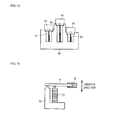
- Patent Document 2 discloses a piezoelectric power generator in which a plurality of generating devices having different resonance frequencies are supported in a cantilever manner. As illustrated in Fig. 13 , this piezoelectric power generator includes a plurality of generating devices 61 to 63 each having one end secured to a base 60 and the other end being a free end, and weights 64 to 66 provided for excitation and attached to the respective free ends of the generating devices 61 to 63. The generating devices 61 to 63 have different lengths. This piezoelectric power generator is designed to generate electric power in a wide frequency range even when the frequency of external vibration varies. However, it is not possible to increase the amount of power generation at a specific frequency.
- Patent Document 3 discloses another piezoelectric power generator. As illustrated in Fig. 14 , this piezoelectric power generator includes a lever 71 having a cantilever structure in which one end thereof is secured to a metal angle 70 and the other end thereof is a free end, a weight 72 attached to the free end of the lever 71, and a multilayer piezoelectric element 73 connected to a midpoint (point of action) of the lever 71.
- This piezoelectric power generator amplifies an external force using the principle of leverage to increase the force applied to the multilayer piezoelectric element 73. However, since only a compressive load in the thickness direction acts on the multilayer piezoelectric element 73, the amount of distortion of the piezoelectric element is not large enough to significantly increase the amount of power generation.
- An object of the present invention is to propose a piezoelectric power generator that amplifies a displacement of a generating device and generates a large amount of electric power.
- the present invention provides a piezoelectric power generator that includes a resonator including a first weight member supported on a base member via a spring means; a second weight member; and a generating device including a vibrating plate having a piezoelectric element bonded to a principal surface thereof, the vibrating plate having one end secured to the first weight member and the other end being a free end to which the second weight member is attached, the generating device being capable of bending and vibrating in an up-and-down direction.
- the first weight member swings at a predetermined frequency about an axis perpendicular to a bending vibration plane of the generating device.
- the first weight member preferably swings in accordance with an external vibration applied to the base member, and the generating device preferably bends and vibrates in synchronization with the swing of the first weight member.
- a feature of the present invention is that an external vibration applied to the base member is not directly transmitted to the generating device, and energy of the external vibration is amplified by the resonator and transmitted to the generating device.
- the resonator converts an up-and-down external vibration to a swing motion about an axis perpendicular to the bending vibration plane of the generating device, so as to swing the first weight member.
- the second weight member moves up and down in synchronization with the swing of the first weight member, it is possible to amplify the bending vibration of the generating device and cause the generating device to bend and vibrate more significantly than in the case where the generating device is directly secured to the base member. This increases bending stress applied to the generating device and increases the amount of power generation.
- a mass of the first weight member is preferably greater than a mass of the second weight member.
- a mass of the first weight member is greater than a mass of the second weight member, since the first weight member has kinetic energy greater than that of the second weight member, the kinetic energy of the first weight member can be effectively supplied to the bending vibration of the generating device. This makes it possible to further amplify the amount of displacement of the generating device.
- a swing axis of the first weight member may be set to be closer to the free end side of the generating device than the center of gravity of the first weight member is.
- the swing axis of the first weight member may be closer to either the fixed end side or the free end side of the generating device than the center of gravity of the first weight member is.
- an angular change occurs simultaneously with the up-and-down change in position of the first weight member that supports the one end of the generating device.
- the amount of displacement of the generating device further increases. This means that the amount of power generation increases.
- a resonance frequency of the resonator is preferably lower than a resonance frequency of the generating device including the second weight member.
- the present inventors examined the piezoelectric power generator which combines the resonator with the generating device, and found that when the resonance frequency of the resonator was lower than that of the generating device, the voltage amplification factor and the power amplification factor were higher than those in the case where the two resonance systems, the resonator and the generating device, had the same resonance frequency.
- the spring constant of the spring means of the resonator and the masses of the first weight member and the second weight member it is possible to amplify the bending displacement of the generating device and increase the amount of power generation.
- the ratio of a resonance frequency f1 of the resonator in the first-order mode to a resonance frequency fa of the generating device including the second weight member preferably satisfies 0.4 ⁇ f1/fa ⁇ 0.95.
- the resonator has a plurality of resonant modes, from the first to higher order modes, depending on the configuration of the spring means.
- a resonance frequency in the first-order mode refers to the lowest of resonance frequencies of the resonator. Vibrational energy in the first-order mode is greater that in higher order modes.
- the resonance frequency of the resonator in the first-order mode is lower than the resonance frequency of the generating device, the voltage amplification factor and the power amplification factor are higher.
- the frequency ratio f1/fa is in the range of 0.4 to 0.95. If the frequency ratio f1/fa is less than 0.4, the spring constant of the spring means is too low and, due to the lack of restoring force, the voltage amplification factor and the power amplification factor tend to be lower than those when the frequency ratio f1/fa is in the range described above. If the frequency ratio f1/fa is greater than 0.95, the spring constant of the spring means is too high and, because the swing of the first weight member is reduced, the voltage amplification factor and the power amplification factor tend to be lower than those when the frequency ratio f1/fa is in the range described above.
- the spring means of the resonator may include a plurality of coil springs. Using a plurality of coil springs, which have good linearity, makes it possible to vibrate the first weight member in a mode for swinging about a horizontal axis.
- the resonator converts an external vibration to a swing motion about an axis perpendicular to the bending vibration plane of the generating device, and the second weight member moves up and down in synchronization with the swing of the first weight member. Since this amplifies the bending vibration of the generating device, the generating device can bend and vibrate more significantly than in the case where the generating device is directly secured to the base member. It is thus possible to increase the amount of power generation.
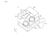
- FIGs. 1 and 2 illustrate a first embodiment of a piezoelectric power generator according to the present invention.
- a piezoelectric power generator A of the present embodiment includes a resonator 10 and a cantilever-type generating device 20.
- the resonator 10 includes a base member 11, a spring means 12, and a first weight member 13 elastically supported on the base member 11 via the spring means 12.
- the base member 11 of the present embodiment is a flat platelike member, the base member 11 may be part of a case or the like, and may be of any shape as long as it can receive an external vibration.
- the first weight member 13 of the present embodiment is L-shaped in lateral view, and is composed of a flat support plate portion 13a and a support base portion 13b standing at a back end of the support plate portion 13a.
- the first weight member 13 is formed by a rigid mass body, such as a metal body.
- the first weight member 13 is a swinging weight member having the function of swinging the generating device 20.
- the spring means 12 includes two coil springs 12a and 12b interposed between the base member 11 and the support plate portion 13a of the first weight member 13.
- the coil springs 12a and 12b of the present embodiment have the same spring constant, but they may have different spring constants.
- the coil springs 12a and 12b are disposed directly below the generating device 20, and spaced apart in the length direction (Y-axis direction).
- the coil springs 12a and 12b are each formed by a coil spring having a spring constant of 0.04 N/mm to 0.50 N/mm.
- the generating device 20 includes a vibrating plate 21, such as a metal plate, and a piezoelectric element 22 bonded to either one or both principal surfaces of the vibrating plate 21.
- the vibrating plate 21 extends along the support plate portion 13a.
- One end 21a of the vibrating plate 21 is secured to the upper surface of the support base portion 13b of the first weight member 13, whereas the other end of the vibrating plate 21 is a free end.
- the other end of the vibrating plate 21 forms a weight mounting portion 21b having a wide shape.
- a second weight member 23 is attached to the lower surface of the weight mounting portion 21b of the vibrating plate 21.
- the second weight member 23 is formed by a mass body, such as a metal body.
- the second weight member 23 is a weight member for amplifying the amount of displacement, the weight member having the function of increasing the amount of displacement of the generating device 20.
- the generating device 20 is capable of bending and vibrating in the up-and-down direction.
- the width direction of the generating device 20 is defined an X-axis direction
- the length direction of the generating device 20 is defined as a Y-axis direction
- the thickness direction (up-and-down direction) of the generating device 20 is defined as a Z-axis direction.
- a bending vibration plane of the generating device 20 is a Y-Z axial plane.
- the vibrating plate 21 and the piezoelectric element 22 of the generating device 20 are in the shape of an isosceles triangle that gradually narrows from the one end 21a toward the other end of the vibrating plate 21, but they may be in the shape of a rectangle having a constant width or may be of any shape.
- the generating device 20 has a unimorph structure in which the piezoelectric element 22 made of piezoelectric ceramics or the like is bonded to one principal surface of the vibrating plate 21.
- the metal plate 21 has a thickness of 75 ⁇ m and is made of 42 Ni
- the piezoelectric element 22 has a thickness of 75 ⁇ m and is made of PZT piezoelectric ceramics.
- the generating device 20 of the present embodiment has a unimorph structure
- the generating device 20 may have a bimorph structure in which the piezoelectric element 22 is bonded to both principal surfaces of the vibrating plate 21.
- the position for bonding the piezoelectric element 22 is not limited to a region outside the one end 21a of the vibrating plate 21 secured to the support base portion 13b as in the present embodiment, and may be a region including the one end 21a.
- piezoelectric element 22 When the piezoelectric element 22 is bonded to the lower principal surface of the vibrating plate 21, a compressive stress always acts on the piezoelectric element 22 because of the influence of gravity acting on the second weight member 23.
- Piezoelectric ceramics generally has a higher mechanical strength against compressive stress than against tensile stress. Therefore, by bonding the piezoelectric element 22 in a direction in which the compressive stress acts, it is possible to improve the durability of the piezoelectric element 22 made of piezoelectric ceramics.
- the piezoelectric element 22 may be made of any material that allows direct conversion of mechanical energy to electrical energy. Besides piezoelectric ceramics, an organic piezoelectric material or a dielectric polymer material may be used as the material of the piezoelectric element 22.
- Charge collecting electrodes are formed on both surfaces of the piezoelectric element 22, and the charge collecting electrode on one of the surfaces is electrically connected to the vibrating plate 21.
- the charge collecting electrodes on the piezoelectric element 22 are connected to a rectifier and electric storage circuit 25 (see Fig. 2 ).
- the rectifier and electric storage circuit 25 has the function of rectifying and smoothing the output from the piezoelectric element 22 and storing power.
- the rectifier and electric storage circuit which is publicly known, is not described in detail here.
- the height dimension of the piezoelectric power generator A can be reduced.
- the second weight member 23 and the support plate portion 13a of the first weight member 13 have a space therebetween, so that even when the first weight member 13 is displaced maximally, the second weight member 23 and the support plate portion 13a of the first weight member 13 can be prevented from coming into contact with each other.
- a resonance frequency (first-order resonance point) of the generating device 20 can be changed by varying, for example, the Young's modulus, length, width, or thickness of the vibrating plate 21 or the mass of the second weight member 23.
- the resonance frequency of the generating device 20 is designed to be 15 Hz on the assumption that the piezoelectric power generator A is mounted on someone's clothes or belongings, or on vehicles such as bicycles or cars.
- the mass of the first weight member 13 is preferably greater than the mass of the second weight member 23.
- the mass of the first weight member 13 is 24.0 g and the mass of the second weight member 23 is 10.2 g.
- the mass of the first weight member 13 is greater than the mass of the second weight member 23, if an external vibration is applied to the base member 11, the first weight member 13 has kinetic energy greater than that of the second weight member 23, and the kinetic energy of the first weight member 13 can be effectively supplied to the generating device 20. This makes it possible to further amplify the amount of displacement of the generating device 20.
- Fig. 3 illustrates a displacement of the piezoelectric power generator A in the first-order mode of the resonator 10.
- the piezoelectric element 22 is omitted in Fig. 3 .
- Solid lines represent a state of displacement
- dot-and-dash lines represent a state of standstill in Fig. 3 .
- the resonator 10 swings about a swing axis CS perpendicular to the bending vibration plane of the generating device 20.
- the swing axis CS is parallel to the X-axis.
- the swing axis CS of the first weight member 13 is closer to the free end side of the generating device 20 than the center of gravity G of the first weight member 13 is. That is, in the first-order mode, the swing axis CS is near the coil spring 12b.
- the coil spring 12b expands and contracts very little, whereas the coil spring 12a expands and contracts significantly.
- the generating device 20 bends and vibrates up and down. For example, when the first weight member 13 swings clockwise as illustrated in Fig. 3(a) , the second weight member 23 is swung upward and the generating device 20 bends in a concave shape.
- the location of the swing axis CS may change depending on the settings. It is only necessary that the swing axis CS be closer to the free end side of the generating device 20 than the center of gravity G of the first weight member 13 is.
- Fig. 4 illustrates a displacement of the piezoelectric power generator A in the second-order mode of the resonator 10.
- the piezoelectric element 22 is omitted in Fig. 4 .
- Solid lines represent a state of displacement
- dot-and-dash lines represent a state of standstill in Fig. 4 .
- the first weight member 13 is swung up and down by the spring means 12.
- the resonator 10 swings about the swing axis CS perpendicular to the bending vibration plane of the generating device 20.
- the swing axis CS is parallel to the X-axis.
- the swing axis CS of the first weight member 13 is closer to the fixed end side of the generating device 20 than the center of gravity G of the first weight member 13 is. That is, in the second-order mode, the swing axis CS is near the center of the support base portion 13b of the first weight member 13. The amount of expansion and contraction of the coil spring 12b is greater than that of the coil spring 12a on the fixed end side of the generating device 20.
- the first weight member 13 swings counterclockwise as illustrated in Fig. 4(a)
- the second weight member 23 is displaced downward and the generating device 20 bends in a convex shape.
- the first weight member 13 swings clockwise as illustrated in Fig.
- the second weight member 23 is displaced upward and the generating device 20 bends in a concave shape.
- the amount of displacement of the generating device 20 in the second-order mode is smaller than that in the first-order mode, but is greater than that in the case where the generating device 20 is directly secured to the base member 11.
- Fig. 4 illustrates an example where the swing axis CS is located near the center of the support base portion 13b, the location of the swing axis CS may change depending on the settings. It is only necessary that the swing axis CS be closer to the fixed end side of the generating device 20 than the center of gravity G of the first weight member 13 is.
- Figs. 3 and 4 illustrate resonant modes that occur when the resonance frequency of the resonator 10 in the first-order mode is set to be lower than the resonance frequency of the generating device 20.
- Different resonant modes may occur if the resonance frequency of the resonator 10 in the first-order mode is set to be higher than the resonance frequency of the generating device 20 or if the configuration of the spring means 12 is changed.
- the resonance frequency of the resonator 10 in the first-order mode can be determined by the spring constant of the spring means 12 or the mass of the first weight member 13.
- the resonance frequency of the generating device 20 can be determined by the mass of the second weight member 23 or the spring constant of the vibrating plate 21.
- Fig. 5 illustrates frequency characteristics of a voltage amplification factor and a power amplification factor of the piezoelectric power generator A obtained with different spring constants of the coil springs 12a and 12b of the spring means 12 of the resonator 10.
- a characteristic of the generating device 20 alone is also shown. The calculations were made on the assumption that the acceleration of input of an external vibration to the base member 11 was 100 mG, and that the generated voltage and power were voltage output and power consumed, with a matching resistor connected.
- the first-order mode of the resonator 10 was used as a dominant mode.
- the piezoelectric power generator A which combines the resonator 10 with the generating device 20, it is possible to provide a voltage amplification factor which is 1.9 to 5.1 times greater than that with the generating device 20 alone, and a power amplification factor which is 3.6 to 16.0 times greater than that with the generating device 20 alone.
- the mechanism is that, under the same mass condition of the first weight member 13 of the resonator 10, as the spring constant of the coil springs 12a and 12b forming the spring means 12 decreases, the amount of deformation of the coil springs 12a and 12b increases and a larger amount of kinetic energy is stored in the coil springs 12a and 12b, and hence a larger amount of energy flows from the resonator 10 to the generating device 20.
- the spring constant is too small, the voltage amplification factor and the power amplification factor decrease. This is because the coil springs 12a and 12b are too soft to ensure sufficient restoring force against deformation.
- Fig. 6 illustrates displacement-frequency characteristics of the resonator 10 alone and the generating device 20 alone.
- the spring constant of the coil springs 12a and 12b is 0.12 N/mm.
- the generating device 20 alone there is a resonance point at about 15 Hz.
- the resonator 10 which uses two coil springs 12a and 12b there are resonance points at about 11 Hz and about 20 Hz in the first-order mode and in the second-order mode, respectively.
- the dominant resonant mode of the piezoelectric power generator A is a mode obtained by coupling the resonance of the resonator 10 in the first-order mode to the resonance of the generating device 20. Therefore, a relationship between the resonance frequency of the resonator 10 in the first-order mode and the resonance frequency of the generating device 20 will be examined.
- Fig. 7 illustrates a relationship between a spring constant and resonator-normalized frequencies (i.e., a value obtained by normalizing the resonance frequency of the resonator 10 in the first-order mode to the resonance frequency of the generating device 20, and a value obtained by normalizing the resonance frequency of the resonator 10 in the second-order mode to the resonance frequency of the generating device 20).
- a line where the resonator-normalized frequency is 1.0 represents the resonance point (15 Hz) of the generating device 20.
- the resonator-normalized frequency in the first-order mode is 1.0 or less, and the resonance frequency of the resonator 10 in the first-order mode is lower than the resonance frequency of the generating device 20.
- the spring constant of the coil springs 12a and 12b is 0.07 N/mm or less
- the resonator-normalized frequency in the second-order mode is also 1.0 or less, and the resonance frequency of the resonator 10 in the second-order mode is lower than the resonance frequency of the generating device 20.
- the resonance frequency of the resonator 10 in the first-order mode is designed to be lower than the resonance frequency of the generating device 20
- the voltage amplification factor and the power amplification factor are higher than those when the two resonance systems, the resonator 10 and the generating device 20, have the same resonance frequency.
- the definition of designing the resonance frequency to be lower, as described above, may be to design such that -3 dB widths (half-widths) of resonance frequency bands of the generating device 20 and the resonator 10 do not overlap with each other.
- Fig. 8(a) illustrates a relationship between a resonator-normalized frequency and a voltage amplification factor
- Fig. 8(b) illustrates a relationship between a resonator-normalized frequency and a power amplification factor
- Fig. 8(c) illustrates a relationship between a resonator-normalized frequency and a piezoelectric generator-normalized frequency.
- Fig. 8(a) illustrates a relationship between a resonator-normalized frequency and a voltage amplification factor
- Fig. 8(b) illustrates a relationship between a resonator-normalized frequency and a power amplification factor
- Fig. 8(c) illustrates a relationship between a resonator-normalized frequency and a piezoelectric generator-normalized frequency.
- a resonator-normalized frequency is a value (f1/fa) obtained by normalizing the resonance frequency of the resonator 10 in the first-order mode to the resonance frequency of the generating device 20, and a piezoelectric generator-normalized frequency is a value obtained by normalizing the resonance frequency of the piezoelectric power generator A to the resonance frequency of the generating device 20 alone.
- both the voltage amplification factor and the power amplification factor gradually decrease when the resonator-normalized frequency is 1 or more.
- the resonator-normalized frequency is 1 or less, as the resonator-normalized frequency decreases, both the voltage amplification factor and the power amplification factor increase and reach their maximum values at about a resonator-normalized frequency of 0.5.
- the resonance frequency of the resonator in the first-order mode is lower than the resonance frequency of the generating device 20, the voltage and the power are amplified more effectively than when the resonator 10 and the generating device 20 have the same resonance frequency.
- the maximum amplification effect is achieved when the resonator 10 is designed such that the resonator-normalized frequency is in the range of 0.40 to 0.95.
- the voltage amplification factor and the power amplification factor tend to decrease when the resonator-normalized frequency is less than 0.4. This is because the coil springs 12a and 12b forming the spring means 12 are too soft to ensure sufficient restoring force against deformation.
- the resonator-normalized frequency and the piezoelectric generator-normalized frequency are substantially proportional when the resonator-normalized frequency is less than 0.6.
- the slope decreases and the piezoelectric generator-normalized frequency gradually approaches 1.
- the vibration of the resonator 10 decreases and the resonance frequency of the piezoelectric power generator becomes closer to the resonance frequency of the generating device 20.
- Fig. 9 illustrates a second embodiment of the piezoelectric power generator according to the present invention.
- a piezoelectric power generator B of the present embodiment uses four coil springs 12c to 12f as the spring means 12.
- the coil springs 12c to 12f are spaced in the X-direction on both sides of the generating device 20, and are also spaced in the Y-direction.
- the piezoelectric power generator B of the present embodiment is the same as the piezoelectric power generator A of the first embodiment, except for the configuration of the spring means 12.
- Using the four coil springs 12c to 12f as the spring means 12 in the present embodiment stabilizes the position of the swing axis CS of the first weight member 13, and reduces movement in the right-and-left direction (i.e., swing about the Y-axis). It is thus possible to efficiently convert an external vibration to a swing of the first weight member 13, further amplify the amount of displacement of the generating device 20, and increase the amount of power generated by the piezoelectric power generator B. Note that any number of coil springs can be used in any arrangement.
- Fig. 10 illustrates a third embodiment of the piezoelectric power generator according to the present invention.
- a piezoelectric power generator C of the present embodiment uses four U-shaped leaf springs 12g to 12j as the spring means 12.
- the arrangement of the leaf springs 12g to 12j is the same as the arrangement of the coil springs 12c to 12f illustrated in Fig. 9 .
- the piezoelectric power generator C of the present embodiment is the same as the piezoelectric power generator A of the first embodiment, except for the configuration of the spring means 12.
- the effects of the present embodiment are the same as those of the second embodiment.
- Using the leaf springs, instead of the coil springs, as the spring means 12 facilitates attachment of the spring means 12 to the base member 11 and the first weight member 13. Note that the leaf springs do not necessarily need to be U-shaped, and the number of the leaf springs does not necessarily need to be four.
- Fig. 11 illustrates a generating device used in a fourth embodiment of the piezoelectric power generator according to the present invention.
- a piezoelectric power generator D of the present embodiment uses a generating device 30 as the generating device.
- the generating device 30 of the present embodiment includes a vibrating plate 31 such as a metal plate, piezoelectric elements 32a to 32c bonded to both principal surfaces of the vibrating plate 31, and a second weight member 33 for excitation. Note that the piezoelectric elements 32a to 32c are omitted in Fig. 11(a) .
- the piezoelectric power generator D of the present embodiment is the same as the piezoelectric power generator A of the first embodiment, except for the configuration of the generating device 30.
- a fixed portion 31d which is one end of the vibrating plate 31, is secured to the upper surface of the support base portion 13b of the first weight member 13.
- the other end of the vibrating plate 31 is a free end, and is provided with the second weight member 33 attached thereto.
- the vibrating plate 31 has a U-shaped through portion between the one end and the other end thereof.
- the through portion has a portion located adjacent to the one end of the vibrating plate 31 and extending in the X-axis direction; and two portions located between the one end and the other end of the vibrating plate 31 and adjacent to respective end portions of the vibrating plate 31 along the longitudinal direction, the two portions extending in the Y-axis direction.
- the other end of the vibrating plate 31 has notches on both sides of the portion to which the second weight member 33 is attached.
- the vibrating plate 31 has first to third arm portions 31a to 31c and first and second folded portions 31e and 31f.
- the first arm portions 31a and the second arm portions 31b are provided in pairs on both right and left sides of the third arm portion 31c. Therefore, the vibrating plate 31 is symmetric with respect to an axial line CL passing through the center of the third arm portion 31c.
- the first arm portions 31a are located at the respective end portions of the vibrating plate 31 along the longitudinal direction and extend in the Y-axis direction.
- the first arm portions 31a gradually narrow from the fixed portion 31d toward the second weight member 33.
- first arm portions 31a are connected to the fixed portion 31d, whereas the other ends of the first arm portions 31a are connected via the respective first folded portions 31e to respective one ends of the second arm portions 31b.
- the second arm portions 31b face the respective first arm portions 31a across the through portion, and extend in the Y-axis direction.
- the second arm portions 31b gradually narrow from the fixed portion 31d toward the second weight member 33.
- One ends of the second arm portions 31b are connected via the respective first folded portions 31e to the respective other ends of the first arm portions 31a, whereas the other ends of the second arm portions 31b are connected via the respective second folded portions 31f to one end of the third arm portion 31c.
- the third arm portion 31c faces the second arm portions 31b across the notches, and extends in the Y-axis direction.
- the third arm portion 31c gradually narrows from the fixed portion 31d toward the second weight member 33.
- One end of the third arm portion 31c is connected via the second folded portions 31f to the other ends of the second arm portions 31b, whereas the other end of the third arm portion 31c is a free end to which the second weight member 33 is attached.
- the piezoelectric elements 32a are bonded to the respective lower surfaces of the first arm portions 31a, the piezoelectric elements 32b are bonded to the respective upper surfaces of the second arm portions 31b, and the piezoelectric element 32c is bonded to the lower surface of the third arm portion 31c.
- the piezoelectric elements 32a to 32c are geometrically similar to the corresponding arm portions.
- the piezoelectric power generator D of the present embodiment substantially the same amount of bending stress is generated in each arm portion, and the bending stress is substantially uniformly distributed across the length of each arm portion. Therefore, the amount of power generated by the piezoelectric power generator D is greater than that generated by any of the piezoelectric power generators A to C of the first to third embodiments, each of which includes the vibrating plate 21 formed by a single arm portion.
- the piezoelectric power generator of the present invention is not limited to the embodiments described above, and various changes may be made thereto.
- the spring means is not limited to coil springs or leaf springs, and the number of the spring means is not limited to two or four.
- the first weight member is L-shaped in lateral view in the embodiments described above, the first weight member may be of any shape.
- the fixed position of the generating device is not limited to one end portion as in the embodiments described above.
- a guide means may be added which guides the first weight member and allows it to move only in the up-and-down direction. Examples of the guide means include a wall or a post that is secured to or integrally formed with the base member 11, and slidably guides both sides of the first weight member 13.
Landscapes
- General Electrical Machinery Utilizing Piezoelectricity, Electrostriction Or Magnetostriction (AREA)
- Apparatuses For Generation Of Mechanical Vibrations (AREA)
Abstract
Description
- The present invention relates to a piezoelectric power generator that generates electric power by converting mechanical energy to electrical energy using a piezoelectric effect.
- Conventionally, various piezoelectric power generators have been proposed which generate electric power using a piezoelectric effect.
Patent Document 1 discloses a piezoelectric power generator having a cantilever structure such as that illustrated inFig. 12 . This piezoelectric power generator includes agenerating device 52 and aweight 53. One end of the generatingdevice 52 is secured to a frame-like supportingmember 51, and the other end of the generatingdevice 52 is a free end. Theweight 53 is provided for excitation and is attached to the free end of the generatingdevice 52. The generatingdevice 52 has a unimorph structure in which apiezoelectric element 52b is bonded to one principal surface of ametal plate 52a. Theentire generating device 52 is in the shape of a rectangular parallelepiped. When an external vibration acts on the piezoelectric power generator, a free vibration is excited in the generatingdevice 52 by the action of theweight 53, and an electric charge can be generated by a piezoelectric effect of thepiezoelectric element 52b. The generated electric charge is extracted from charge collecting electrodes formed on the front and back surfaces of thepiezoelectric element 52b. - For example, like power generators that use vibration of human walk or vibration of bicycles or cars, there are power generators used in a relatively low-frequency vibration region. By bringing the natural frequency of a generating device close to the frequency of such a low-frequency external vibration, it is possible to significantly vibrate the generating device and increase the amount of power generation. The amount of power generation of a piezoelectric element is determined by a value obtained by dividing the product of the square of a piezoelectric constant of a piezoelectric body forming the piezoelectric element, the square of stress applied to the piezoelectric body, and a volume of the piezoelectric body by a dielectric constant of the piezoelectric body. If the material of the piezoelectric body is the same, the amount of power generation W is proportional to the product of the square of stress σ applied to the piezoelectric body and a volume V of the piezoelectric body as given by the expression W∝σ2 × V.
Therefore, to increase the amount of power generation W, it is effective to increase both the stress σ applied to the piezoelectric body and the volume V of the piezoelectric body. In particular, the stress σ has a greater influence on the amount of power generation W than the volume V does. To increase the stress σ applied to the piezoelectric body, it is effective to increase the amount of displacement of the generating device. However, the amount of displacement of the generating device cannot be significantly increased simply by supporting the generatingdevice 52 with the supportingmember 51 in a cantilever manner. - Patent Document 2 discloses a piezoelectric power generator in which a plurality of generating devices having different resonance frequencies are supported in a cantilever manner. As illustrated in
Fig. 13 , this piezoelectric power generator includes a plurality of generatingdevices 61 to 63 each having one end secured to abase 60 and the other end being a free end, andweights 64 to 66 provided for excitation and attached to the respective free ends of the generatingdevices 61 to 63. The generatingdevices 61 to 63 have different lengths. This piezoelectric power generator is designed to generate electric power in a wide frequency range even when the frequency of external vibration varies. However, it is not possible to increase the amount of power generation at a specific frequency. -
Patent Document 3 discloses another piezoelectric power generator. As illustrated inFig. 14 , this piezoelectric power generator includes alever 71 having a cantilever structure in which one end thereof is secured to ametal angle 70 and the other end thereof is a free end, aweight 72 attached to the free end of thelever 71, and a multilayerpiezoelectric element 73 connected to a midpoint (point of action) of thelever 71. This piezoelectric power generator amplifies an external force using the principle of leverage to increase the force applied to the multilayerpiezoelectric element 73. However, since only a compressive load in the thickness direction acts on the multilayerpiezoelectric element 73, the amount of distortion of the piezoelectric element is not large enough to significantly increase the amount of power generation. -
- Patent Document 1: Japanese Patent No.
3170965 - Patent Document 2: Japanese Unexamined Patent Application Publication No.
7-245970 - Patent Document 3: Japanese Unexamined Patent Application Publication No.
11-146663 - An object of the present invention is to propose a piezoelectric power generator that amplifies a displacement of a generating device and generates a large amount of electric power.
- To achieve the object described above, the present invention provides a piezoelectric power generator that includes a resonator including a first weight member supported on a base member via a spring means; a second weight member; and a generating device including a vibrating plate having a piezoelectric element bonded to a principal surface thereof, the vibrating plate having one end secured to the first weight member and the other end being a free end to which the second weight member is attached, the generating device being capable of bending and vibrating in an up-and-down direction. The first weight member swings at a predetermined frequency about an axis perpendicular to a bending vibration plane of the generating device. The first weight member preferably swings in accordance with an external vibration applied to the base member, and the generating device preferably bends and vibrates in synchronization with the swing of the first weight member.
- A feature of the present invention is that an external vibration applied to the base member is not directly transmitted to the generating device, and energy of the external vibration is amplified by the resonator and transmitted to the generating device. In particular, the resonator converts an up-and-down external vibration to a swing motion about an axis perpendicular to the bending vibration plane of the generating device, so as to swing the first weight member. When the second weight member moves up and down in synchronization with the swing of the first weight member, it is possible to amplify the bending vibration of the generating device and cause the generating device to bend and vibrate more significantly than in the case where the generating device is directly secured to the base member. This increases bending stress applied to the generating device and increases the amount of power generation.
- A mass of the first weight member is preferably greater than a mass of the second weight member. When a mass of the first weight member is greater than a mass of the second weight member, since the first weight member has kinetic energy greater than that of the second weight member, the kinetic energy of the first weight member can be effectively supplied to the bending vibration of the generating device. This makes it possible to further amplify the amount of displacement of the generating device.
- A swing axis of the first weight member may be set to be closer to the free end side of the generating device than the center of gravity of the first weight member is. The swing axis of the first weight member may be closer to either the fixed end side or the free end side of the generating device than the center of gravity of the first weight member is. However, when the swing axis of the first weight member is closer to the free end side of the generating device, an angular change occurs simultaneously with the up-and-down change in position of the first weight member that supports the one end of the generating device. Under the synergistic action of the angular change and the up-and-down displacement at the fixed end of the generating device, the amount of displacement of the generating device further increases. This means that the amount of power generation increases.
- A resonance frequency of the resonator is preferably lower than a resonance frequency of the generating device including the second weight member. The present inventors examined the piezoelectric power generator which combines the resonator with the generating device, and found that when the resonance frequency of the resonator was lower than that of the generating device, the voltage amplification factor and the power amplification factor were higher than those in the case where the two resonance systems, the resonator and the generating device, had the same resonance frequency. Thus, by appropriately setting the spring constant of the spring means of the resonator and the masses of the first weight member and the second weight member, it is possible to amplify the bending displacement of the generating device and increase the amount of power generation.
- The ratio of a resonance frequency f1 of the resonator in the first-order mode to a resonance frequency fa of the generating device including the second weight member preferably satisfies 0.4 ≤ f1/fa ≤ 0.95. The resonator has a plurality of resonant modes, from the first to higher order modes, depending on the configuration of the spring means. A resonance frequency in the first-order mode refers to the lowest of resonance frequencies of the resonator. Vibrational energy in the first-order mode is greater that in higher order modes. As described above, when the resonance frequency of the resonator in the first-order mode is lower than the resonance frequency of the generating device, the voltage amplification factor and the power amplification factor are higher. It is most effective particularly when the frequency ratio f1/fa is in the range of 0.4 to 0.95. If the frequency ratio f1/fa is less than 0.4, the spring constant of the spring means is too low and, due to the lack of restoring force, the voltage amplification factor and the power amplification factor tend to be lower than those when the frequency ratio f1/fa is in the range described above. If the frequency ratio f1/fa is greater than 0.95, the spring constant of the spring means is too high and, because the swing of the first weight member is reduced, the voltage amplification factor and the power amplification factor tend to be lower than those when the frequency ratio f1/fa is in the range described above.
- The spring means of the resonator may include a plurality of coil springs. Using a plurality of coil springs, which have good linearity, makes it possible to vibrate the first weight member in a mode for swinging about a horizontal axis.
- As described above, in the present invention, the resonator converts an external vibration to a swing motion about an axis perpendicular to the bending vibration plane of the generating device, and the second weight member moves up and down in synchronization with the swing of the first weight member. Since this amplifies the bending vibration of the generating device, the generating device can bend and vibrate more significantly than in the case where the generating device is directly secured to the base member. It is thus possible to increase the amount of power generation.
-
- [
Fig. 1] Fig. 1 is a perspective view of a first embodiment of a piezoelectric power generator according to the present invention. - [
Fig. 2] Fig. 2 is a lateral view of the piezoelectric power generator illustrated inFig. 1 , the lateral view illustrating the piezoelectric power generator at a standstill. - [
Fig. 3] Fig. 3 is a lateral view of the piezoelectric power generator illustrated inFig. 1 , the lateral view illustrating a displacement of the piezoelectric power generator in the first-order mode. - [
Fig. 4] Fig. 4 is a lateral view of the piezoelectric power generator illustrated inFig. 1 , the lateral view illustrating a displacement of the piezoelectric power generator in the second-order mode. - [
Fig. 5] Fig. 5 illustrates frequency characteristics of a voltage amplification factor and a power amplification factor of the piezoelectric power generator obtained with different spring constants of coil springs of a resonator. - [
Fig. 6] Fig. 6 illustrates displacement-frequency characteristics of the resonator alone and a generating device alone. - [
Fig. 7] Fig. 7 illustrates a relationship between a spring constant and a resonator-normalized frequency. - [
Fig. 8] Fig. 8 illustrates a relationship between a resonator-normalized frequency and a voltage amplification factor, a relationship between a resonator-normalized frequency and a power amplification factor, and a relationship between a resonator-normalized frequency and a piezoelectric generator-normalized frequency. - [
Fig. 9] Fig. 9 is a perspective view of a second embodiment of the piezoelectric power generator according to the present invention. - [
Fig. 10] Fig. 10 is a perspective view of a third embodiment of the piezoelectric power generator according to the present invention. - [
Fig. 11] Fig. 11 provides a perspective view and a plan view of a generating device used in a fourth embodiment of the piezoelectric power generator according to the present invention. - [
Fig. 12] Fig. 12 is a perspective view of a piezoelectric power generator described inPatent Document 1. - [
Fig. 13] Fig. 13 is a cross-sectional view of a piezoelectric power generator described in Patent Document 2. - [
Fig. 14] Fig. 14 is a lateral view of a piezoelectric power generator described inPatent Document 3. -
Figs. 1 and2 illustrate a first embodiment of a piezoelectric power generator according to the present invention. A piezoelectric power generator A of the present embodiment includes aresonator 10 and a cantilever-type generating device 20. - The
resonator 10 includes abase member 11, a spring means 12, and afirst weight member 13 elastically supported on thebase member 11 via the spring means 12. Although thebase member 11 of the present embodiment is a flat platelike member, thebase member 11 may be part of a case or the like, and may be of any shape as long as it can receive an external vibration. Thefirst weight member 13 of the present embodiment is L-shaped in lateral view, and is composed of a flatsupport plate portion 13a and asupport base portion 13b standing at a back end of thesupport plate portion 13a. Thefirst weight member 13 is formed by a rigid mass body, such as a metal body. Thefirst weight member 13 is a swinging weight member having the function of swinging the generatingdevice 20. The spring means 12 includes twocoil springs base member 11 and thesupport plate portion 13a of thefirst weight member 13. The coil springs 12a and 12b of the present embodiment have the same spring constant, but they may have different spring constants. The coil springs 12a and 12b are disposed directly below the generatingdevice 20, and spaced apart in the length direction (Y-axis direction). For example, thecoil springs - The generating
device 20 includes a vibratingplate 21, such as a metal plate, and apiezoelectric element 22 bonded to either one or both principal surfaces of the vibratingplate 21. The vibratingplate 21 extends along thesupport plate portion 13a. Oneend 21a of the vibratingplate 21 is secured to the upper surface of thesupport base portion 13b of thefirst weight member 13, whereas the other end of the vibratingplate 21 is a free end. The other end of the vibratingplate 21 forms aweight mounting portion 21b having a wide shape. Asecond weight member 23 is attached to the lower surface of theweight mounting portion 21b of the vibratingplate 21. Like thefirst weight member 13 described above, thesecond weight member 23 is formed by a mass body, such as a metal body. Thesecond weight member 23 is a weight member for amplifying the amount of displacement, the weight member having the function of increasing the amount of displacement of the generatingdevice 20. Thus, the generatingdevice 20 is capable of bending and vibrating in the up-and-down direction. In the present embodiment, the width direction of the generatingdevice 20 is defined an X-axis direction, the length direction of the generatingdevice 20 is defined as a Y-axis direction, and the thickness direction (up-and-down direction) of the generatingdevice 20 is defined as a Z-axis direction. In this case, a bending vibration plane of the generatingdevice 20 is a Y-Z axial plane. - In the present embodiment, as viewed from above the piezoelectric power generator A, the vibrating
plate 21 and thepiezoelectric element 22 of the generatingdevice 20 are in the shape of an isosceles triangle that gradually narrows from the oneend 21a toward the other end of the vibratingplate 21, but they may be in the shape of a rectangle having a constant width or may be of any shape. The generatingdevice 20 has a unimorph structure in which thepiezoelectric element 22 made of piezoelectric ceramics or the like is bonded to one principal surface of the vibratingplate 21. For example, themetal plate 21 has a thickness of 75 µm and is made of 42 Ni, and thepiezoelectric element 22 has a thickness of 75 µm and is made of PZT piezoelectric ceramics. Although the generatingdevice 20 of the present embodiment has a unimorph structure, the generatingdevice 20 may have a bimorph structure in which thepiezoelectric element 22 is bonded to both principal surfaces of the vibratingplate 21. The position for bonding thepiezoelectric element 22 is not limited to a region outside the oneend 21a of the vibratingplate 21 secured to thesupport base portion 13b as in the present embodiment, and may be a region including the oneend 21a. When thepiezoelectric element 22 is bonded to the lower principal surface of the vibratingplate 21, a compressive stress always acts on thepiezoelectric element 22 because of the influence of gravity acting on thesecond weight member 23. Piezoelectric ceramics generally has a higher mechanical strength against compressive stress than against tensile stress. Therefore, by bonding thepiezoelectric element 22 in a direction in which the compressive stress acts, it is possible to improve the durability of thepiezoelectric element 22 made of piezoelectric ceramics. Thepiezoelectric element 22 may be made of any material that allows direct conversion of mechanical energy to electrical energy. Besides piezoelectric ceramics, an organic piezoelectric material or a dielectric polymer material may be used as the material of thepiezoelectric element 22. - Charge collecting electrodes (not shown) are formed on both surfaces of the
piezoelectric element 22, and the charge collecting electrode on one of the surfaces is electrically connected to the vibratingplate 21. The charge collecting electrodes on thepiezoelectric element 22 are connected to a rectifier and electric storage circuit 25 (seeFig. 2 ). The rectifier andelectric storage circuit 25 has the function of rectifying and smoothing the output from thepiezoelectric element 22 and storing power. The rectifier and electric storage circuit, which is publicly known, is not described in detail here. - In the present embodiment, where the
second weight member 23 is secured to the lower surface of the vibratingplate 21, the height dimension of the piezoelectric power generator A can be reduced. Thesecond weight member 23 and thesupport plate portion 13a of thefirst weight member 13 have a space therebetween, so that even when thefirst weight member 13 is displaced maximally, thesecond weight member 23 and thesupport plate portion 13a of thefirst weight member 13 can be prevented from coming into contact with each other. A resonance frequency (first-order resonance point) of the generatingdevice 20 can be changed by varying, for example, the Young's modulus, length, width, or thickness of the vibratingplate 21 or the mass of thesecond weight member 23. For example, the resonance frequency of the generatingdevice 20 is designed to be 15 Hz on the assumption that the piezoelectric power generator A is mounted on someone's clothes or belongings, or on vehicles such as bicycles or cars. - The mass of the
first weight member 13 is preferably greater than the mass of thesecond weight member 23. In the present embodiment, for example, the mass of thefirst weight member 13 is 24.0 g and the mass of thesecond weight member 23 is 10.2 g. When the mass of thefirst weight member 13 is greater than the mass of thesecond weight member 23, if an external vibration is applied to thebase member 11, thefirst weight member 13 has kinetic energy greater than that of thesecond weight member 23, and the kinetic energy of thefirst weight member 13 can be effectively supplied to the generatingdevice 20. This makes it possible to further amplify the amount of displacement of the generatingdevice 20. -
Fig. 3 illustrates a displacement of the piezoelectric power generator A in the first-order mode of theresonator 10. Thepiezoelectric element 22 is omitted inFig. 3 . Solid lines represent a state of displacement, and dot-and-dash lines represent a state of standstill inFig. 3 . As illustrated, when an up-and-down external vibration F acts on thebase member 11, thefirst weight member 13 is swung up and down by the spring means 12. Theresonator 10 swings about a swing axis CS perpendicular to the bending vibration plane of the generatingdevice 20. The swing axis CS is parallel to the X-axis. In the first-order mode, the swing axis CS of thefirst weight member 13 is closer to the free end side of the generatingdevice 20 than the center of gravity G of thefirst weight member 13 is. That is, in the first-order mode, the swing axis CS is near thecoil spring 12b. Thecoil spring 12b expands and contracts very little, whereas thecoil spring 12a expands and contracts significantly. In synchronization with the swing of thefirst weight member 13, the generatingdevice 20 bends and vibrates up and down. For example, when thefirst weight member 13 swings clockwise as illustrated inFig. 3(a) , thesecond weight member 23 is swung upward and the generatingdevice 20 bends in a concave shape. On the other hand, when thefirst weight member 13 swings counterclockwise as illustrated inFig. 3(b) , thesecond weight member 23 is swung downward and the generatingdevice 20 bends in a convex shape. Thus, when the oneend 21a of the generating device 20 (thesupport base portion 13b of the first weight member 13), which is the fixed end, moves up and down, an angular change occurs at the same time and the amount of displacement of the generatingdevice 20 is amplified. As a result, a stress applied to thepiezoelectric element 22 of the generatingdevice 20 is greater than that in the case where the generatingdevice 20 is directly secured to thebase member 11 and the amount of power generation is larger. Note that althoughFig. 3 illustrates an example where the swing axis CS is located diagonally above thecoil spring 12b, the location of the swing axis CS may change depending on the settings. It is only necessary that the swing axis CS be closer to the free end side of the generatingdevice 20 than the center of gravity G of thefirst weight member 13 is. -
Fig. 4 illustrates a displacement of the piezoelectric power generator A in the second-order mode of theresonator 10. Thepiezoelectric element 22 is omitted inFig. 4 . Solid lines represent a state of displacement, and dot-and-dash lines represent a state of standstill inFig. 4 . As illustrated, in the second-order mode, as in the first-order mode, when the up-and-down external vibration F acts on thebase member 11, thefirst weight member 13 is swung up and down by the spring means 12. Theresonator 10 swings about the swing axis CS perpendicular to the bending vibration plane of the generatingdevice 20. The swing axis CS is parallel to the X-axis. In the second-order mode, the swing axis CS of thefirst weight member 13 is closer to the fixed end side of the generatingdevice 20 than the center of gravity G of thefirst weight member 13 is. That is, in the second-order mode, the swing axis CS is near the center of thesupport base portion 13b of thefirst weight member 13. The amount of expansion and contraction of thecoil spring 12b is greater than that of thecoil spring 12a on the fixed end side of the generatingdevice 20. In this mode, when thefirst weight member 13 swings counterclockwise as illustrated inFig. 4(a) , thesecond weight member 23 is displaced downward and the generatingdevice 20 bends in a convex shape. On the other hand, when thefirst weight member 13 swings clockwise as illustrated inFig. 4(b) , thesecond weight member 23 is displaced upward and the generatingdevice 20 bends in a concave shape. The amount of displacement of the generatingdevice 20 in the second-order mode is smaller than that in the first-order mode, but is greater than that in the case where the generatingdevice 20 is directly secured to thebase member 11. Note that althoughFig. 4 illustrates an example where the swing axis CS is located near the center of thesupport base portion 13b, the location of the swing axis CS may change depending on the settings. It is only necessary that the swing axis CS be closer to the fixed end side of the generatingdevice 20 than the center of gravity G of thefirst weight member 13 is. -
Figs. 3 and4 illustrate resonant modes that occur when the resonance frequency of theresonator 10 in the first-order mode is set to be lower than the resonance frequency of the generatingdevice 20. Different resonant modes may occur if the resonance frequency of theresonator 10 in the first-order mode is set to be higher than the resonance frequency of the generatingdevice 20 or if the configuration of the spring means 12 is changed. The resonance frequency of theresonator 10 in the first-order mode can be determined by the spring constant of the spring means 12 or the mass of thefirst weight member 13. The resonance frequency of the generatingdevice 20 can be determined by the mass of thesecond weight member 23 or the spring constant of the vibratingplate 21. -
Fig. 5 illustrates frequency characteristics of a voltage amplification factor and a power amplification factor of the piezoelectric power generator A obtained with different spring constants of thecoil springs resonator 10. For comparison, a characteristic of the generatingdevice 20 alone is also shown. The calculations were made on the assumption that the acceleration of input of an external vibration to thebase member 11 was 100 mG, and that the generated voltage and power were voltage output and power consumed, with a matching resistor connected. In the case ofFig. 5 , the first-order mode of theresonator 10 was used as a dominant mode. - In the case of the generating
device 20 alone, voltage and power reach their peak values when the frequency of external vibration is about 15 Hz, which is the resonance frequency of the generating device. In the case of the piezoelectric power generator A which combines theresonator 10 with the generatingdevice 20, as the spring constant decreases, frequencies corresponding to the peak values of the voltage amplification factor and the power amplification factor decrease and the peak values of the voltage amplification factor and the power amplification factor increase. This means that the resonance frequency of the piezoelectric power generator A increases in proportion to the spring constant. The voltage amplification factor and the power amplification factor reach their maximum values when the spring constant is 0.05 N/mm, and decrease dramatically when the spring constant becomes smaller than that. With the piezoelectric power generator A which combines theresonator 10 with the generatingdevice 20, it is possible to provide a voltage amplification factor which is 1.9 to 5.1 times greater than that with the generatingdevice 20 alone, and a power amplification factor which is 3.6 to 16.0 times greater than that with the generatingdevice 20 alone. - The mechanism is that, under the same mass condition of the
first weight member 13 of theresonator 10, as the spring constant of thecoil springs coil springs coil springs resonator 10 to the generatingdevice 20. When the spring constant is too small, the voltage amplification factor and the power amplification factor decrease. This is because thecoil springs - A description will now be given of a relationship between resonance frequencies of the
resonator 10 and the generatingdevice 20 necessary for power amplification.Fig. 6 illustrates displacement-frequency characteristics of theresonator 10 alone and the generatingdevice 20 alone. For theresonator 10, the spring constant of thecoil springs device 20 alone, there is a resonance point at about 15 Hz. As for theresonator 10, which uses twocoil springs resonator 10 in the first-order mode to the resonance of the generatingdevice 20. Therefore, a relationship between the resonance frequency of theresonator 10 in the first-order mode and the resonance frequency of the generatingdevice 20 will be examined. -
Fig. 7 illustrates a relationship between a spring constant and resonator-normalized frequencies (i.e., a value obtained by normalizing the resonance frequency of theresonator 10 in the first-order mode to the resonance frequency of the generatingdevice 20, and a value obtained by normalizing the resonance frequency of theresonator 10 in the second-order mode to the resonance frequency of the generating device 20). A line where the resonator-normalized frequency is 1.0 represents the resonance point (15 Hz) of the generatingdevice 20. When the spring constant of thecoil springs resonator 10 in the first-order mode is lower than the resonance frequency of the generatingdevice 20. When the spring constant of thecoil springs resonator 10 in the second-order mode is lower than the resonance frequency of the generatingdevice 20. - As is apparent from
Figs. 6 and 7 , when the resonance frequency of theresonator 10 in the first-order mode is designed to be lower than the resonance frequency of the generatingdevice 20, the voltage amplification factor and the power amplification factor are higher than those when the two resonance systems, theresonator 10 and the generatingdevice 20, have the same resonance frequency. The definition of designing the resonance frequency to be lower, as described above, may be to design such that -3 dB widths (half-widths) of resonance frequency bands of the generatingdevice 20 and theresonator 10 do not overlap with each other. -
Fig. 8(a) illustrates a relationship between a resonator-normalized frequency and a voltage amplification factor,Fig. 8(b) illustrates a relationship between a resonator-normalized frequency and a power amplification factor, andFig. 8(c) illustrates a relationship between a resonator-normalized frequency and a piezoelectric generator-normalized frequency. InFig. 8 , a resonator-normalized frequency is a value (f1/fa) obtained by normalizing the resonance frequency of theresonator 10 in the first-order mode to the resonance frequency of the generatingdevice 20, and a piezoelectric generator-normalized frequency is a value obtained by normalizing the resonance frequency of the piezoelectric power generator A to the resonance frequency of the generatingdevice 20 alone. - As for the relationship between the voltage amplification factor and the power amplification factor, as illustrated in
Figs. 8(a) and 8(b) , both the voltage amplification factor and the power amplification factor gradually decrease when the resonator-normalized frequency is 1 or more. When the resonator-normalized frequency is 1 or less, as the resonator-normalized frequency decreases, both the voltage amplification factor and the power amplification factor increase and reach their maximum values at about a resonator-normalized frequency of 0.5. When the resonance frequency of the resonator in the first-order mode is lower than the resonance frequency of the generatingdevice 20, the voltage and the power are amplified more effectively than when theresonator 10 and the generatingdevice 20 have the same resonance frequency. The maximum amplification effect is achieved when theresonator 10 is designed such that the resonator-normalized frequency is in the range of 0.40 to 0.95. The voltage amplification factor and the power amplification factor tend to decrease when the resonator-normalized frequency is less than 0.4. This is because thecoil springs - Referring to
Fig. 8(c) , the resonator-normalized frequency and the piezoelectric generator-normalized frequency are substantially proportional when the resonator-normalized frequency is less than 0.6. As the resonator-normalized frequency increases, the slope decreases and the piezoelectric generator-normalized frequency gradually approaches 1. Hence, by increasing the spring constant of thecoil springs resonator 10 decreases and the resonance frequency of the piezoelectric power generator becomes closer to the resonance frequency of the generatingdevice 20. Thus, with the structure of a piezoelectric power generator which combines a resonator with a generating device as in the present invention, it is possible to adjust the resonance frequency of the piezoelectric power generator by adjusting the spring constant of spring means of the resonator without changing the resonance frequency of the generating device. -
Fig. 9 illustrates a second embodiment of the piezoelectric power generator according to the present invention. A piezoelectric power generator B of the present embodiment uses fourcoil springs 12c to 12f as the spring means 12. The coil springs 12c to 12f are spaced in the X-direction on both sides of the generatingdevice 20, and are also spaced in the Y-direction. The piezoelectric power generator B of the present embodiment is the same as the piezoelectric power generator A of the first embodiment, except for the configuration of the spring means 12. - Using the four
coil springs 12c to 12f as the spring means 12 in the present embodiment stabilizes the position of the swing axis CS of thefirst weight member 13, and reduces movement in the right-and-left direction (i.e., swing about the Y-axis). It is thus possible to efficiently convert an external vibration to a swing of thefirst weight member 13, further amplify the amount of displacement of the generatingdevice 20, and increase the amount of power generated by the piezoelectric power generator B. Note that any number of coil springs can be used in any arrangement. -
Fig. 10 illustrates a third embodiment of the piezoelectric power generator according to the present invention. A piezoelectric power generator C of the present embodiment uses fourU-shaped leaf springs 12g to 12j as the spring means 12. The arrangement of theleaf springs 12g to 12j is the same as the arrangement of the coil springs 12c to 12f illustrated inFig. 9 . The piezoelectric power generator C of the present embodiment is the same as the piezoelectric power generator A of the first embodiment, except for the configuration of the spring means 12. The effects of the present embodiment are the same as those of the second embodiment. Using the leaf springs, instead of the coil springs, as the spring means 12 facilitates attachment of the spring means 12 to thebase member 11 and thefirst weight member 13. Note that the leaf springs do not necessarily need to be U-shaped, and the number of the leaf springs does not necessarily need to be four. -
Fig. 11 illustrates a generating device used in a fourth embodiment of the piezoelectric power generator according to the present invention. A piezoelectric power generator D of the present embodiment uses agenerating device 30 as the generating device. The generatingdevice 30 of the present embodiment includes a vibratingplate 31 such as a metal plate,piezoelectric elements 32a to 32c bonded to both principal surfaces of the vibratingplate 31, and asecond weight member 33 for excitation. Note that thepiezoelectric elements 32a to 32c are omitted inFig. 11(a) . The piezoelectric power generator D of the present embodiment is the same as the piezoelectric power generator A of the first embodiment, except for the configuration of the generatingdevice 30. - A fixed
portion 31d, which is one end of the vibratingplate 31, is secured to the upper surface of thesupport base portion 13b of thefirst weight member 13. The other end of the vibratingplate 31 is a free end, and is provided with thesecond weight member 33 attached thereto. The vibratingplate 31 has a U-shaped through portion between the one end and the other end thereof. The through portion has a portion located adjacent to the one end of the vibratingplate 31 and extending in the X-axis direction; and two portions located between the one end and the other end of the vibratingplate 31 and adjacent to respective end portions of the vibratingplate 31 along the longitudinal direction, the two portions extending in the Y-axis direction. The other end of the vibratingplate 31 has notches on both sides of the portion to which thesecond weight member 33 is attached. Specifically, the vibratingplate 31 has first to third arm portions 31a to 31c and first and second foldedportions second arm portions 31b are provided in pairs on both right and left sides of thethird arm portion 31c. Therefore, the vibratingplate 31 is symmetric with respect to an axial line CL passing through the center of thethird arm portion 31c. The first arm portions 31a are located at the respective end portions of the vibratingplate 31 along the longitudinal direction and extend in the Y-axis direction. The first arm portions 31a gradually narrow from the fixedportion 31d toward thesecond weight member 33. One ends of the first arm portions 31a are connected to the fixedportion 31d, whereas the other ends of the first arm portions 31a are connected via the respective first foldedportions 31e to respective one ends of thesecond arm portions 31b. Thesecond arm portions 31b face the respective first arm portions 31a across the through portion, and extend in the Y-axis direction. Thesecond arm portions 31b gradually narrow from the fixedportion 31d toward thesecond weight member 33. One ends of thesecond arm portions 31b are connected via the respective first foldedportions 31e to the respective other ends of the first arm portions 31a, whereas the other ends of thesecond arm portions 31b are connected via the respective second foldedportions 31f to one end of thethird arm portion 31c. Thethird arm portion 31c faces thesecond arm portions 31b across the notches, and extends in the Y-axis direction. Thethird arm portion 31c gradually narrows from the fixedportion 31d toward thesecond weight member 33. One end of thethird arm portion 31c is connected via the second foldedportions 31f to the other ends of thesecond arm portions 31b, whereas the other end of thethird arm portion 31c is a free end to which thesecond weight member 33 is attached. - The
piezoelectric elements 32a are bonded to the respective lower surfaces of the first arm portions 31a, the piezoelectric elements 32b are bonded to the respective upper surfaces of thesecond arm portions 31b, and the piezoelectric element 32c is bonded to the lower surface of thethird arm portion 31c. Thepiezoelectric elements 32a to 32c are geometrically similar to the corresponding arm portions. - In the piezoelectric power generator D of the present embodiment, substantially the same amount of bending stress is generated in each arm portion, and the bending stress is substantially uniformly distributed across the length of each arm portion. Therefore, the amount of power generated by the piezoelectric power generator D is greater than that generated by any of the piezoelectric power generators A to C of the first to third embodiments, each of which includes the vibrating
plate 21 formed by a single arm portion. - The piezoelectric power generator of the present invention is not limited to the embodiments described above, and various changes may be made thereto. The spring means is not limited to coil springs or leaf springs, and the number of the spring means is not limited to two or four. Although the first weight member is L-shaped in lateral view in the embodiments described above, the first weight member may be of any shape. The fixed position of the generating device is not limited to one end portion as in the embodiments described above. To prevent the first weight member of the resonator from laterally moving (i.e., swinging about the Y-axis) in response to an external vibration applied thereto, a guide means may be added which guides the first weight member and allows it to move only in the up-and-down direction. Examples of the guide means include a wall or a post that is secured to or integrally formed with the
base member 11, and slidably guides both sides of thefirst weight member 13. -
- A to D: piezoelectric power generator
- 10: resonator
- 11: base member
- 12: spring means
- 12a, 12b: coil spring
- 13: first weight member
- 20: generating device
- 21: vibrating plate
- 22: piezoelectric element
- 23: second weight member
- 25: rectifier and electric storage circuit
- 30: generating device
- 31: vibrating plate
- 31a to 31c: first to third arm portions
- 31e, 31f: first and second folded portions
- 32a to 32c: piezoelectric element
- 33: second weight member
Claims (7)
- A piezoelectric power generator comprising:a resonator including a first weight member supported on a base member via a spring means;a second weight member; anda generating device including a vibrating plate having a piezoelectric element bonded to a principal surface thereof, the vibrating plate having one end secured to the first weight member and the other end being a free end to which the second weight member is attached, the generating device being capable of bending and vibrating in an up-and-down direction,wherein the first weight member swings at a predetermined frequency about an axis perpendicular to a bending vibration plane of the generating device.
- The piezoelectric power generator according to Claim 1, wherein the first weight member swings in accordance with an external vibration applied to the base member, and the generating device bends and vibrates in synchronization with the swing of the first weight member.
- The piezoelectric power generator according to Claim 1 or 2, wherein a mass of the first weight member is greater than a mass of the second weight member.
- The piezoelectric power generator according to any one of Claims 1 to 3, wherein a swing axis of the first weight member is closer to the free end side of the generating device than the center of gravity of the first weight member is.
- The piezoelectric power generator according to any one of Claims 1 to 4, wherein a resonance frequency of the resonator is lower than a resonance frequency of the generating device including the second weight member.
- The piezoelectric power generator according to Claim 5, wherein the ratio of a resonance frequency f1 of the resonator in the first-order mode to a resonance frequency fa of the generating device including the second weight member satisfies 0.4 ≤ f1/fa ≤ 0.95.
- The piezoelectric power generator according to any one of Claims 1 to 6, wherein the spring means of the resonator includes a plurality of coil springs.
Applications Claiming Priority (2)
| Application Number | Priority Date | Filing Date | Title |
|---|---|---|---|
| JP2011084967 | 2011-04-07 | ||
| PCT/JP2012/058799 WO2012137695A1 (en) | 2011-04-07 | 2012-04-02 | Piezoelectric power generator |
Publications (3)
| Publication Number | Publication Date |
|---|---|
| EP2662971A1 true EP2662971A1 (en) | 2013-11-13 |
| EP2662971A4 EP2662971A4 (en) | 2014-08-20 |
| EP2662971B1 EP2662971B1 (en) | 2016-01-20 |
Family
ID=46969095
Family Applications (1)
| Application Number | Title | Priority Date | Filing Date |
|---|---|---|---|
| EP12768220.1A Active EP2662971B1 (en) | 2011-04-07 | 2012-04-02 | Piezoelectric power generator |
Country Status (5)
| Country | Link |
|---|---|
| US (1) | US9246414B2 (en) |
| EP (1) | EP2662971B1 (en) |
| JP (1) | JP5761336B2 (en) |
| CN (1) | CN103460592B (en) |
| WO (1) | WO2012137695A1 (en) |
Cited By (2)
| Publication number | Priority date | Publication date | Assignee | Title |
|---|---|---|---|---|
| WO2014170922A1 (en) * | 2013-04-15 | 2014-10-23 | Politecnico Di Torino | Multi-frequency vibration piezoelectric harvester device |
| AU2015208446B2 (en) * | 2015-04-22 | 2018-11-29 | Beijing University Of Technology | Multi-mode vibration power generator |
Families Citing this family (30)
| Publication number | Priority date | Publication date | Assignee | Title |
|---|---|---|---|---|
| CN104521130B (en) * | 2012-08-07 | 2017-03-08 | 株式会社村田制作所 | piezoelectric generating device |
| GB2518918B (en) * | 2012-11-13 | 2016-07-06 | Perpetuum Ltd | An electromechanical generator for, and method of, converting mechanical vibrational energy into electrical energy |
| EP2922194B1 (en) * | 2012-11-19 | 2017-12-06 | Panasonic Intellectual Property Management Co., Ltd. | Power-generating device |
| WO2014116794A1 (en) * | 2013-01-23 | 2014-07-31 | The Regents Of The University Of Michigan | Piezoelectric vibrational energy harvester |
| JP6174053B2 (en) * | 2013-01-30 | 2017-08-09 | 住友理工株式会社 | Magnetostrictive vibration power generator |
| DE112013006824B4 (en) | 2013-03-13 | 2021-07-22 | Panasonic Corporation | Power generator |
| JP6294638B2 (en) * | 2013-11-26 | 2018-03-14 | 矢崎総業株式会社 | Electronic key charging system |
| WO2015087537A1 (en) * | 2013-12-12 | 2015-06-18 | パナソニックIpマネジメント株式会社 | Vibration power-generation device, vibration monitoring device and system |
| JP6195255B2 (en) | 2013-12-13 | 2017-09-13 | 住友理工株式会社 | Vibration power generator |
| JP6196549B2 (en) * | 2013-12-26 | 2017-09-13 | 株式会社京三製作所 | Power generation mechanism and sensor |
| KR102229140B1 (en) * | 2014-09-11 | 2021-03-18 | 한국전자통신연구원 | device for harvesting energy, manufacturing method, and wireless apparatus including the same |
| JP2016077037A (en) * | 2014-10-03 | 2016-05-12 | 東洋ゴム工業株式会社 | Power generation device and power generation device design method |
| JP6388163B2 (en) * | 2015-01-30 | 2018-09-12 | 住友理工株式会社 | Power generator |
| US10447135B2 (en) * | 2015-09-28 | 2019-10-15 | The Curators Of The University Of Missouri | Device for generating electrical power from low frequency oscillations |
| JP5996078B1 (en) * | 2015-10-19 | 2016-09-21 | 株式会社トライフォース・マネジメント | Power generation element |
| JP2017184444A (en) * | 2016-03-30 | 2017-10-05 | 株式会社ロイヤルパーツ | Vibration generator |
| TWI634264B (en) * | 2017-01-13 | 2018-09-01 | 研能科技股份有限公司 | Air pump |
| WO2018142714A1 (en) * | 2017-01-31 | 2018-08-09 | パナソニックIpマネジメント株式会社 | Power generation device |
| JP6474868B1 (en) | 2017-08-29 | 2019-02-27 | 株式会社トライフォース・マネジメント | Power generation element |
| KR101971735B1 (en) * | 2017-09-21 | 2019-04-26 | 한국세라믹기술원 | Multi-resonance piezoelectric energy harvester |
| JP6671660B2 (en) * | 2017-12-22 | 2020-03-25 | 株式会社ワコー | Power generation element |
| JP7128639B2 (en) * | 2018-03-20 | 2022-08-31 | 株式会社鷺宮製作所 | Vibration booster and vibration generator |
| JP7027252B2 (en) | 2018-05-25 | 2022-03-01 | 株式会社東芝 | Vibration sensor and sensor module |
| JP6647498B2 (en) * | 2018-10-17 | 2020-02-14 | 株式会社トライフォース・マネジメント | Power generation element |
| US11283003B2 (en) | 2019-04-08 | 2022-03-22 | Ramin Sadr | Green energy harvesting methods for novel class of batteries and power supplies |
| FI130145B (en) * | 2019-04-15 | 2023-03-13 | Tikitin Oy | Microelectromechanical resonator |
| JP7311885B2 (en) * | 2019-07-30 | 2023-07-20 | エミック株式会社 | Vibration generator |
| WO2021060906A1 (en) * | 2019-09-27 | 2021-04-01 | 송찰스기석 | Self-powered sensor, and monitoring system including same |
| CN110925156A (en) * | 2019-12-05 | 2020-03-27 | 西安戴森电子技术有限公司 | Vehicle-mounted energy collecting system |
| CN114884398A (en) * | 2022-06-14 | 2022-08-09 | 浙江工商大学 | Piezoelectric vibration energy collector and design method thereof |
Family Cites Families (14)
| Publication number | Priority date | Publication date | Assignee | Title |
|---|---|---|---|---|
| JP3170965B2 (en) * | 1993-08-04 | 2001-05-28 | セイコーエプソン株式会社 | Generators and portable equipment |
| JPH07245970A (en) * | 1994-03-02 | 1995-09-19 | Calsonic Corp | Piezoelectric power generator |
| JPH11146663A (en) | 1997-11-11 | 1999-05-28 | Sony Corp | Piezoelectric generator |
| JP2001231272A (en) | 2000-02-17 | 2001-08-24 | Usc Corp | Piezoelectric generator |
| JP2001275370A (en) | 2000-03-27 | 2001-10-05 | Toto Ltd | Piezoelectric hydraulic power generator |
| JP3768520B1 (en) * | 2005-04-13 | 2006-04-19 | 太平洋セメント株式会社 | Power generator |
| WO2007061610A1 (en) * | 2005-11-18 | 2007-05-31 | Par Technologies, Llc | Human powered piezoelectric power generating device |
| ITRM20070079A1 (en) * | 2007-02-15 | 2008-08-16 | Wisepower S R L | BISTABLE PIEZOELECTRIC GENERATOR. |
| JP2009247106A (en) * | 2008-03-31 | 2009-10-22 | Taiyo Yuden Co Ltd | Piezo-electric vibratory generator |
| US7948153B1 (en) * | 2008-05-14 | 2011-05-24 | Sandia Corporation | Piezoelectric energy harvester having planform-tapered interdigitated beams |
| DE102008038293A1 (en) * | 2008-08-18 | 2010-03-18 | Albert-Ludwigs-Universität Freiburg | Method and device for generating electrical energy from a mechanical excitation oscillation |
| CN101359882B (en) * | 2008-08-29 | 2011-08-17 | 清华大学 | Piezoelectric vibration energy collecting apparatus with adjustable resonance frequency |
| MY162273A (en) * | 2008-09-29 | 2017-05-31 | Mimos Berhad | A device for maximum detection of vibrating energy for harvesting energy |
| KR101325645B1 (en) * | 2010-09-16 | 2013-11-06 | 한국전자통신연구원 | electric device used the energy harvesting |
-
2012
- 2012-04-02 EP EP12768220.1A patent/EP2662971B1/en active Active
- 2012-04-02 CN CN201280016568.1A patent/CN103460592B/en active Active
- 2012-04-02 JP JP2013508849A patent/JP5761336B2/en active Active
- 2012-04-02 WO PCT/JP2012/058799 patent/WO2012137695A1/en not_active Ceased
-
2013
- 2013-08-09 US US13/963,068 patent/US9246414B2/en active Active
Cited By (2)
| Publication number | Priority date | Publication date | Assignee | Title |
|---|---|---|---|---|
| WO2014170922A1 (en) * | 2013-04-15 | 2014-10-23 | Politecnico Di Torino | Multi-frequency vibration piezoelectric harvester device |
| AU2015208446B2 (en) * | 2015-04-22 | 2018-11-29 | Beijing University Of Technology | Multi-mode vibration power generator |
Also Published As
| Publication number | Publication date |
|---|---|
| JP5761336B2 (en) | 2015-08-12 |
| WO2012137695A1 (en) | 2012-10-11 |
| CN103460592A (en) | 2013-12-18 |
| US9246414B2 (en) | 2016-01-26 |
| EP2662971B1 (en) | 2016-01-20 |
| US20130320807A1 (en) | 2013-12-05 |
| EP2662971A4 (en) | 2014-08-20 |
| JPWO2012137695A1 (en) | 2014-07-28 |
| CN103460592B (en) | 2016-04-06 |
Similar Documents
| Publication | Publication Date | Title |
|---|---|---|
| EP2662971B1 (en) | Piezoelectric power generator | |
| JP5720703B2 (en) | Piezoelectric generator | |
| CN109997305B (en) | Vibration power generation element | |
| US9893655B2 (en) | Piezoelectric power generation apparatus | |
| JP4546471B2 (en) | Strain energy shuttle apparatus and method for vibration energy collection | |
| US10291107B2 (en) | Power generator, power generator set and power generation system | |
| JP2003209980A (en) | Vibration generator | |
| US9106160B2 (en) | Monolithic energy harvesting system, apparatus, and method | |
| KR101053256B1 (en) | Energy harvester | |
| EP2670043A1 (en) | Piezoelectric power generating apparatus | |
| JP2014511664A (en) | Device for converting mechanical energy into electrical energy | |
| JP2011152004A (en) | Power generation unit and power generation devic | |
| JPWO2014141557A1 (en) | Power generator | |
| WO2016020481A1 (en) | Energy harvester | |
| JP2017055594A (en) | Power generation device mounting structure and power generation method | |
| KR101713798B1 (en) | Wideband piezoelectric energy harvester | |
| WO2020230509A1 (en) | Vibration power generation device | |
| JP6309698B1 (en) | Power generation device and power generation element | |
| JP2023076648A (en) | Vibration power generation element | |
| JP2020188630A (en) | Vibration power generator | |
| Patel et al. | Vibrational energy harvesting devices | |
| KR20150059511A (en) | Non-contact type energy harvester using magnetoelectric effect | |
| KR20130033223A (en) | Frequency up-conversion vibration energy harvesting device | |
| JP2021069280A (en) | Vibration power generation element | |
| JP2014225576A (en) | Piezoelectric type vibration power generating device |
Legal Events
| Date | Code | Title | Description |
|---|---|---|---|
| PUAI | Public reference made under article 153(3) epc to a published international application that has entered the european phase |
Free format text: ORIGINAL CODE: 0009012 |
|
| 17P | Request for examination filed |
Effective date: 20130719 |
|
| AK | Designated contracting states |
Kind code of ref document: A1 Designated state(s): AL AT BE BG CH CY CZ DE DK EE ES FI FR GB GR HR HU IE IS IT LI LT LU LV MC MK MT NL NO PL PT RO RS SE SI SK SM TR |
|
| DAX | Request for extension of the european patent (deleted) | ||
| A4 | Supplementary search report drawn up and despatched |
Effective date: 20140722 |
|
| RIC1 | Information provided on ipc code assigned before grant |
Ipc: H02N 2/18 20060101AFI20140716BHEP |
|
| GRAP | Despatch of communication of intention to grant a patent |
Free format text: ORIGINAL CODE: EPIDOSNIGR1 |
|
| INTG | Intention to grant announced |
Effective date: 20150722 |
|
| GRAS | Grant fee paid |
Free format text: ORIGINAL CODE: EPIDOSNIGR3 |
|
| GRAA | (expected) grant |
Free format text: ORIGINAL CODE: 0009210 |
|
| AK | Designated contracting states |
Kind code of ref document: B1 Designated state(s): AL AT BE BG CH CY CZ DE DK EE ES FI FR GB GR HR HU IE IS IT LI LT LU LV MC MK MT NL NO PL PT RO RS SE SI SK SM TR |
|
| REG | Reference to a national code |
Ref country code: GB Ref legal event code: FG4D |
|
| REG | Reference to a national code |
Ref country code: CH Ref legal event code: EP |
|
| REG | Reference to a national code |
Ref country code: IE Ref legal event code: FG4D |
|
| REG | Reference to a national code |
Ref country code: AT Ref legal event code: REF Ref document number: 772126 Country of ref document: AT Kind code of ref document: T Effective date: 20160215 |
|
| REG | Reference to a national code |
Ref country code: DE Ref legal event code: R096 Ref document number: 602012014177 Country of ref document: DE |
|
| REG | Reference to a national code |
Ref country code: LT Ref legal event code: MG4D Ref country code: NL Ref legal event code: MP Effective date: 20160120 |
|
| REG | Reference to a national code |
Ref country code: AT Ref legal event code: MK05 Ref document number: 772126 Country of ref document: AT Kind code of ref document: T Effective date: 20160120 |
|
| PG25 | Lapsed in a contracting state [announced via postgrant information from national office to epo] |
Ref country code: NL Free format text: LAPSE BECAUSE OF FAILURE TO SUBMIT A TRANSLATION OF THE DESCRIPTION OR TO PAY THE FEE WITHIN THE PRESCRIBED TIME-LIMIT Effective date: 20160120 |
|
| PG25 | Lapsed in a contracting state [announced via postgrant information from national office to epo] |
Ref country code: GR Free format text: LAPSE BECAUSE OF FAILURE TO SUBMIT A TRANSLATION OF THE DESCRIPTION OR TO PAY THE FEE WITHIN THE PRESCRIBED TIME-LIMIT Effective date: 20160421 Ref country code: FI Free format text: LAPSE BECAUSE OF FAILURE TO SUBMIT A TRANSLATION OF THE DESCRIPTION OR TO PAY THE FEE WITHIN THE PRESCRIBED TIME-LIMIT Effective date: 20160120 Ref country code: HR Free format text: LAPSE BECAUSE OF FAILURE TO SUBMIT A TRANSLATION OF THE DESCRIPTION OR TO PAY THE FEE WITHIN THE PRESCRIBED TIME-LIMIT Effective date: 20160120 Ref country code: IT Free format text: LAPSE BECAUSE OF FAILURE TO SUBMIT A TRANSLATION OF THE DESCRIPTION OR TO PAY THE FEE WITHIN THE PRESCRIBED TIME-LIMIT Effective date: 20160120 Ref country code: ES Free format text: LAPSE BECAUSE OF FAILURE TO SUBMIT A TRANSLATION OF THE DESCRIPTION OR TO PAY THE FEE WITHIN THE PRESCRIBED TIME-LIMIT Effective date: 20160120 Ref country code: NO Free format text: LAPSE BECAUSE OF FAILURE TO SUBMIT A TRANSLATION OF THE DESCRIPTION OR TO PAY THE FEE WITHIN THE PRESCRIBED TIME-LIMIT Effective date: 20160420 |
|
| PG25 | Lapsed in a contracting state [announced via postgrant information from national office to epo] |
Ref country code: LV Free format text: LAPSE BECAUSE OF FAILURE TO SUBMIT A TRANSLATION OF THE DESCRIPTION OR TO PAY THE FEE WITHIN THE PRESCRIBED TIME-LIMIT Effective date: 20160120 Ref country code: LT Free format text: LAPSE BECAUSE OF FAILURE TO SUBMIT A TRANSLATION OF THE DESCRIPTION OR TO PAY THE FEE WITHIN THE PRESCRIBED TIME-LIMIT Effective date: 20160120 Ref country code: PT Free format text: LAPSE BECAUSE OF FAILURE TO SUBMIT A TRANSLATION OF THE DESCRIPTION OR TO PAY THE FEE WITHIN THE PRESCRIBED TIME-LIMIT Effective date: 20160520 Ref country code: BE Free format text: LAPSE BECAUSE OF NON-PAYMENT OF DUE FEES Effective date: 20160430 Ref country code: IS Free format text: LAPSE BECAUSE OF FAILURE TO SUBMIT A TRANSLATION OF THE DESCRIPTION OR TO PAY THE FEE WITHIN THE PRESCRIBED TIME-LIMIT Effective date: 20160520 Ref country code: RS Free format text: LAPSE BECAUSE OF FAILURE TO SUBMIT A TRANSLATION OF THE DESCRIPTION OR TO PAY THE FEE WITHIN THE PRESCRIBED TIME-LIMIT Effective date: 20160120 Ref country code: PL Free format text: LAPSE BECAUSE OF FAILURE TO SUBMIT A TRANSLATION OF THE DESCRIPTION OR TO PAY THE FEE WITHIN THE PRESCRIBED TIME-LIMIT Effective date: 20160120 Ref country code: AT Free format text: LAPSE BECAUSE OF FAILURE TO SUBMIT A TRANSLATION OF THE DESCRIPTION OR TO PAY THE FEE WITHIN THE PRESCRIBED TIME-LIMIT Effective date: 20160120 Ref country code: SE Free format text: LAPSE BECAUSE OF FAILURE TO SUBMIT A TRANSLATION OF THE DESCRIPTION OR TO PAY THE FEE WITHIN THE PRESCRIBED TIME-LIMIT Effective date: 20160120 |
|
| REG | Reference to a national code |
Ref country code: DE Ref legal event code: R097 Ref document number: 602012014177 Country of ref document: DE |
|
| PG25 | Lapsed in a contracting state [announced via postgrant information from national office to epo] |
Ref country code: DK Free format text: LAPSE BECAUSE OF FAILURE TO SUBMIT A TRANSLATION OF THE DESCRIPTION OR TO PAY THE FEE WITHIN THE PRESCRIBED TIME-LIMIT Effective date: 20160120 Ref country code: EE Free format text: LAPSE BECAUSE OF FAILURE TO SUBMIT A TRANSLATION OF THE DESCRIPTION OR TO PAY THE FEE WITHIN THE PRESCRIBED TIME-LIMIT Effective date: 20160120 |
|
| PLBE | No opposition filed within time limit |
Free format text: ORIGINAL CODE: 0009261 |
|
| STAA | Information on the status of an ep patent application or granted ep patent |
Free format text: STATUS: NO OPPOSITION FILED WITHIN TIME LIMIT |
|
| PG25 | Lapsed in a contracting state [announced via postgrant information from national office to epo] |
Ref country code: SK Free format text: LAPSE BECAUSE OF FAILURE TO SUBMIT A TRANSLATION OF THE DESCRIPTION OR TO PAY THE FEE WITHIN THE PRESCRIBED TIME-LIMIT Effective date: 20160120 Ref country code: SM Free format text: LAPSE BECAUSE OF FAILURE TO SUBMIT A TRANSLATION OF THE DESCRIPTION OR TO PAY THE FEE WITHIN THE PRESCRIBED TIME-LIMIT Effective date: 20160120 Ref country code: CZ Free format text: LAPSE BECAUSE OF FAILURE TO SUBMIT A TRANSLATION OF THE DESCRIPTION OR TO PAY THE FEE WITHIN THE PRESCRIBED TIME-LIMIT Effective date: 20160120 Ref country code: RO Free format text: LAPSE BECAUSE OF FAILURE TO SUBMIT A TRANSLATION OF THE DESCRIPTION OR TO PAY THE FEE WITHIN THE PRESCRIBED TIME-LIMIT Effective date: 20160120 |
|
| REG | Reference to a national code |
Ref country code: CH Ref legal event code: PL |
|
| 26N | No opposition filed |
Effective date: 20161021 |
|
| GBPC | Gb: european patent ceased through non-payment of renewal fee |
Effective date: 20160420 |
|
| PG25 | Lapsed in a contracting state [announced via postgrant information from national office to epo] |
Ref country code: BE Free format text: LAPSE BECAUSE OF FAILURE TO SUBMIT A TRANSLATION OF THE DESCRIPTION OR TO PAY THE FEE WITHIN THE PRESCRIBED TIME-LIMIT Effective date: 20160120 Ref country code: LU Free format text: LAPSE BECAUSE OF FAILURE TO SUBMIT A TRANSLATION OF THE DESCRIPTION OR TO PAY THE FEE WITHIN THE PRESCRIBED TIME-LIMIT Effective date: 20160402 |
|
| REG | Reference to a national code |
Ref country code: IE Ref legal event code: MM4A |
|
| REG | Reference to a national code |
Ref country code: FR Ref legal event code: ST Effective date: 20161230 |
|
| PG25 | Lapsed in a contracting state [announced via postgrant information from national office to epo] |
Ref country code: GB Free format text: LAPSE BECAUSE OF NON-PAYMENT OF DUE FEES Effective date: 20160420 Ref country code: FR Free format text: LAPSE BECAUSE OF NON-PAYMENT OF DUE FEES Effective date: 20160502 Ref country code: LI Free format text: LAPSE BECAUSE OF NON-PAYMENT OF DUE FEES Effective date: 20160430 Ref country code: CH Free format text: LAPSE BECAUSE OF NON-PAYMENT OF DUE FEES Effective date: 20160430 |
|
| PG25 | Lapsed in a contracting state [announced via postgrant information from national office to epo] |
Ref country code: SI Free format text: LAPSE BECAUSE OF FAILURE TO SUBMIT A TRANSLATION OF THE DESCRIPTION OR TO PAY THE FEE WITHIN THE PRESCRIBED TIME-LIMIT Effective date: 20160120 Ref country code: BG Free format text: LAPSE BECAUSE OF FAILURE TO SUBMIT A TRANSLATION OF THE DESCRIPTION OR TO PAY THE FEE WITHIN THE PRESCRIBED TIME-LIMIT Effective date: 20160420 |
|
| PG25 | Lapsed in a contracting state [announced via postgrant information from national office to epo] |
Ref country code: IE Free format text: LAPSE BECAUSE OF NON-PAYMENT OF DUE FEES Effective date: 20160402 |
|
| PG25 | Lapsed in a contracting state [announced via postgrant information from national office to epo] |
Ref country code: HU Free format text: LAPSE BECAUSE OF FAILURE TO SUBMIT A TRANSLATION OF THE DESCRIPTION OR TO PAY THE FEE WITHIN THE PRESCRIBED TIME-LIMIT; INVALID AB INITIO Effective date: 20120402 Ref country code: CY Free format text: LAPSE BECAUSE OF FAILURE TO SUBMIT A TRANSLATION OF THE DESCRIPTION OR TO PAY THE FEE WITHIN THE PRESCRIBED TIME-LIMIT Effective date: 20160120 |
|
| PG25 | Lapsed in a contracting state [announced via postgrant information from national office to epo] |
Ref country code: MK Free format text: LAPSE BECAUSE OF FAILURE TO SUBMIT A TRANSLATION OF THE DESCRIPTION OR TO PAY THE FEE WITHIN THE PRESCRIBED TIME-LIMIT Effective date: 20160120 Ref country code: MT Free format text: LAPSE BECAUSE OF NON-PAYMENT OF DUE FEES Effective date: 20160430 Ref country code: TR Free format text: LAPSE BECAUSE OF FAILURE TO SUBMIT A TRANSLATION OF THE DESCRIPTION OR TO PAY THE FEE WITHIN THE PRESCRIBED TIME-LIMIT Effective date: 20160120 Ref country code: MC Free format text: LAPSE BECAUSE OF FAILURE TO SUBMIT A TRANSLATION OF THE DESCRIPTION OR TO PAY THE FEE WITHIN THE PRESCRIBED TIME-LIMIT Effective date: 20160120 |
|
| PG25 | Lapsed in a contracting state [announced via postgrant information from national office to epo] |
Ref country code: AL Free format text: LAPSE BECAUSE OF FAILURE TO SUBMIT A TRANSLATION OF THE DESCRIPTION OR TO PAY THE FEE WITHIN THE PRESCRIBED TIME-LIMIT Effective date: 20160120 |
|
| PGFP | Annual fee paid to national office [announced via postgrant information from national office to epo] |
Ref country code: DE Payment date: 20250422 Year of fee payment: 14 |