EP2662124A1 - Trennvorrichtung für rohrförmige Durchflussvorrichtungen - Google Patents
Trennvorrichtung für rohrförmige Durchflussvorrichtungen Download PDFInfo
- Publication number
- EP2662124A1 EP2662124A1 EP20130179568 EP13179568A EP2662124A1 EP 2662124 A1 EP2662124 A1 EP 2662124A1 EP 20130179568 EP20130179568 EP 20130179568 EP 13179568 A EP13179568 A EP 13179568A EP 2662124 A1 EP2662124 A1 EP 2662124A1
- Authority
- EP
- European Patent Office
- Prior art keywords
- discs
- separating device
- annular discs
- brittle
- materials
- Prior art date
- Legal status (The legal status is an assumption and is not a legal conclusion. Google has not performed a legal analysis and makes no representation as to the accuracy of the status listed.)
- Granted
Links
- 238000000926 separation method Methods 0.000 title claims abstract description 25
- 239000000463 material Substances 0.000 claims abstract description 55
- 239000000919 ceramic Substances 0.000 claims abstract description 27
- 230000008878 coupling Effects 0.000 claims abstract description 27
- 238000010168 coupling process Methods 0.000 claims abstract description 27
- 238000005859 coupling reaction Methods 0.000 claims abstract description 27
- 239000011435 rock Substances 0.000 claims abstract description 24
- 239000002245 particle Substances 0.000 claims abstract description 22
- 239000004576 sand Substances 0.000 claims abstract description 22
- 229910010293 ceramic material Inorganic materials 0.000 claims abstract description 15
- 239000011230 binding agent Substances 0.000 claims abstract description 4
- 238000011065 in-situ storage Methods 0.000 claims abstract description 4
- 239000011226 reinforced ceramic Substances 0.000 claims abstract description 4
- 239000000835 fiber Substances 0.000 claims abstract description 3
- 125000006850 spacer group Chemical group 0.000 claims description 35
- 230000006835 compression Effects 0.000 claims description 18
- 238000007906 compression Methods 0.000 claims description 18
- 229910010271 silicon carbide Inorganic materials 0.000 claims description 15
- 229910000831 Steel Inorganic materials 0.000 claims description 14
- 239000007788 liquid Substances 0.000 claims description 14
- HBMJWWWQQXIZIP-UHFFFAOYSA-N silicon carbide Chemical compound [Si+]#[C-] HBMJWWWQQXIZIP-UHFFFAOYSA-N 0.000 claims description 14
- 239000010959 steel Substances 0.000 claims description 14
- 230000002093 peripheral effect Effects 0.000 claims description 12
- 239000007789 gas Substances 0.000 claims description 9
- 238000000034 method Methods 0.000 claims description 7
- 230000008569 process Effects 0.000 claims description 6
- 238000007789 sealing Methods 0.000 claims description 6
- 230000001681 protective effect Effects 0.000 claims description 5
- 239000010935 stainless steel Substances 0.000 claims description 4
- 238000004663 powder metallurgy Methods 0.000 claims description 3
- 229910052580 B4C Inorganic materials 0.000 claims description 2
- INAHAJYZKVIDIZ-UHFFFAOYSA-N boron carbide Chemical compound B12B3B4C32B41 INAHAJYZKVIDIZ-UHFFFAOYSA-N 0.000 claims description 2
- 238000001556 precipitation Methods 0.000 claims description 2
- 239000000843 powder Substances 0.000 abstract description 3
- 229910001018 Cast iron Inorganic materials 0.000 abstract 1
- 239000011225 non-oxide ceramic Substances 0.000 abstract 1
- 229910052575 non-oxide ceramic Inorganic materials 0.000 abstract 1
- 239000011224 oxide ceramic Substances 0.000 abstract 1
- 229910052574 oxide ceramic Inorganic materials 0.000 abstract 1
- 230000007797 corrosion Effects 0.000 description 20
- 238000005260 corrosion Methods 0.000 description 20
- 238000012360 testing method Methods 0.000 description 19
- 230000003628 erosive effect Effects 0.000 description 18
- 238000005299 abrasion Methods 0.000 description 12
- 239000000243 solution Substances 0.000 description 10
- 239000004033 plastic Substances 0.000 description 8
- 229920003023 plastic Polymers 0.000 description 8
- -1 alkalis Substances 0.000 description 7
- 238000005452 bending Methods 0.000 description 7
- 239000012530 fluid Substances 0.000 description 7
- 238000000576 coating method Methods 0.000 description 5
- 238000005553 drilling Methods 0.000 description 5
- 238000009434 installation Methods 0.000 description 5
- 230000007704 transition Effects 0.000 description 5
- XLYOFNOQVPJJNP-UHFFFAOYSA-N water Substances O XLYOFNOQVPJJNP-UHFFFAOYSA-N 0.000 description 5
- 239000002253 acid Substances 0.000 description 4
- 230000008901 benefit Effects 0.000 description 4
- 238000013461 design Methods 0.000 description 4
- 238000004519 manufacturing process Methods 0.000 description 4
- 229920001643 poly(ether ketone) Polymers 0.000 description 4
- 230000035882 stress Effects 0.000 description 4
- 239000004743 Polypropylene Substances 0.000 description 3
- HEMHJVSKTPXQMS-UHFFFAOYSA-M Sodium hydroxide Chemical compound [OH-].[Na+] HEMHJVSKTPXQMS-UHFFFAOYSA-M 0.000 description 3
- 150000007513 acids Chemical class 0.000 description 3
- 230000002411 adverse Effects 0.000 description 3
- 238000002474 experimental method Methods 0.000 description 3
- 239000000203 mixture Substances 0.000 description 3
- 238000011056 performance test Methods 0.000 description 3
- 239000006223 plastic coating Substances 0.000 description 3
- 229920001155 polypropylene Polymers 0.000 description 3
- 238000003466 welding Methods 0.000 description 3
- 230000015572 biosynthetic process Effects 0.000 description 2
- 238000005422 blasting Methods 0.000 description 2
- 230000008859 change Effects 0.000 description 2
- 238000004140 cleaning Methods 0.000 description 2
- 239000011248 coating agent Substances 0.000 description 2
- 238000010276 construction Methods 0.000 description 2
- 229920001971 elastomer Polymers 0.000 description 2
- 239000012065 filter cake Substances 0.000 description 2
- 238000003780 insertion Methods 0.000 description 2
- 230000037431 insertion Effects 0.000 description 2
- 150000001247 metal acetylides Chemical class 0.000 description 2
- 239000003921 oil Substances 0.000 description 2
- 230000021715 photosynthesis, light harvesting Effects 0.000 description 2
- 229920000098 polyolefin Polymers 0.000 description 2
- 239000011148 porous material Substances 0.000 description 2
- 238000003860 storage Methods 0.000 description 2
- 229910018072 Al 2 O 3 Inorganic materials 0.000 description 1
- 229910000851 Alloy steel Inorganic materials 0.000 description 1
- RYGMFSIKBFXOCR-UHFFFAOYSA-N Copper Chemical compound [Cu] RYGMFSIKBFXOCR-UHFFFAOYSA-N 0.000 description 1
- 229920002449 FKM Polymers 0.000 description 1
- 239000002033 PVDF binder Substances 0.000 description 1
- 239000004698 Polyethylene Substances 0.000 description 1
- 229910009043 WC-Co Inorganic materials 0.000 description 1
- 238000004026 adhesive bonding Methods 0.000 description 1
- 230000032683 aging Effects 0.000 description 1
- 230000002902 bimodal effect Effects 0.000 description 1
- 239000001273 butane Substances 0.000 description 1
- 239000003795 chemical substances by application Substances 0.000 description 1
- 229910052804 chromium Inorganic materials 0.000 description 1
- 239000011651 chromium Substances 0.000 description 1
- 229910052802 copper Inorganic materials 0.000 description 1
- 239000010949 copper Substances 0.000 description 1
- 230000007423 decrease Effects 0.000 description 1
- 230000001419 dependent effect Effects 0.000 description 1
- 230000006866 deterioration Effects 0.000 description 1
- KZHJGOXRZJKJNY-UHFFFAOYSA-N dioxosilane;oxo(oxoalumanyloxy)alumane Chemical compound O=[Si]=O.O=[Si]=O.O=[Al]O[Al]=O.O=[Al]O[Al]=O.O=[Al]O[Al]=O KZHJGOXRZJKJNY-UHFFFAOYSA-N 0.000 description 1
- 238000006073 displacement reaction Methods 0.000 description 1
- 238000009826 distribution Methods 0.000 description 1
- 230000000694 effects Effects 0.000 description 1
- 239000000806 elastomer Substances 0.000 description 1
- 229920001973 fluoroelastomer Polymers 0.000 description 1
- 238000011010 flushing procedure Methods 0.000 description 1
- 230000004907 flux Effects 0.000 description 1
- 239000011888 foil Substances 0.000 description 1
- 238000005304 joining Methods 0.000 description 1
- 238000003801 milling Methods 0.000 description 1
- 229910052863 mullite Inorganic materials 0.000 description 1
- IJDNQMDRQITEOD-UHFFFAOYSA-N n-butane Chemical compound CCCC IJDNQMDRQITEOD-UHFFFAOYSA-N 0.000 description 1
- OFBQJSOFQDEBGM-UHFFFAOYSA-N n-pentane Natural products CCCCC OFBQJSOFQDEBGM-UHFFFAOYSA-N 0.000 description 1
- 150000004767 nitrides Chemical class 0.000 description 1
- 229920000573 polyethylene Polymers 0.000 description 1
- 229920000642 polymer Polymers 0.000 description 1
- 229920001343 polytetrafluoroethylene Polymers 0.000 description 1
- 239000004810 polytetrafluoroethylene Substances 0.000 description 1
- 229920002981 polyvinylidene fluoride Polymers 0.000 description 1
- 238000012545 processing Methods 0.000 description 1
- 238000005488 sandblasting Methods 0.000 description 1
- 238000005245 sintering Methods 0.000 description 1
- 239000007787 solid Substances 0.000 description 1
- 229910052596 spinel Inorganic materials 0.000 description 1
- 239000011029 spinel Substances 0.000 description 1
- 229910001220 stainless steel Inorganic materials 0.000 description 1
- 230000004936 stimulating effect Effects 0.000 description 1
- 239000002344 surface layer Substances 0.000 description 1
- UONOETXJSWQNOL-UHFFFAOYSA-N tungsten carbide Chemical compound [W+]#[C-] UONOETXJSWQNOL-UHFFFAOYSA-N 0.000 description 1
- 238000007514 turning Methods 0.000 description 1
- 238000011144 upstream manufacturing Methods 0.000 description 1
Images



Classifications
-
- B—PERFORMING OPERATIONS; TRANSPORTING
- B01—PHYSICAL OR CHEMICAL PROCESSES OR APPARATUS IN GENERAL
- B01D—SEPARATION
- B01D29/00—Filters with filtering elements stationary during filtration, e.g. pressure or suction filters, not covered by groups B01D24/00 - B01D27/00; Filtering elements therefor
- B01D29/44—Edge filtering elements, i.e. using contiguous impervious surfaces
- B01D29/46—Edge filtering elements, i.e. using contiguous impervious surfaces of flat, stacked bodies
-
- B—PERFORMING OPERATIONS; TRANSPORTING
- B01—PHYSICAL OR CHEMICAL PROCESSES OR APPARATUS IN GENERAL
- B01D—SEPARATION
- B01D39/00—Filtering material for liquid or gaseous fluids
- B01D39/14—Other self-supporting filtering material ; Other filtering material
- B01D39/20—Other self-supporting filtering material ; Other filtering material of inorganic material, e.g. asbestos paper, metallic filtering material of non-woven wires
- B01D39/2068—Other inorganic materials, e.g. ceramics
-
- B—PERFORMING OPERATIONS; TRANSPORTING
- B01—PHYSICAL OR CHEMICAL PROCESSES OR APPARATUS IN GENERAL
- B01D—SEPARATION
- B01D46/00—Filters or filtering processes specially modified for separating dispersed particles from gases or vapours
- B01D46/40—Particle separators, e.g. dust precipitators, using edge filters, i.e. using contiguous impervious surfaces
- B01D46/406—Particle separators, e.g. dust precipitators, using edge filters, i.e. using contiguous impervious surfaces of stacked bodies
-
- E—FIXED CONSTRUCTIONS
- E21—EARTH OR ROCK DRILLING; MINING
- E21B—EARTH OR ROCK DRILLING; OBTAINING OIL, GAS, WATER, SOLUBLE OR MELTABLE MATERIALS OR A SLURRY OF MINERALS FROM WELLS
- E21B43/00—Methods or apparatus for obtaining oil, gas, water, soluble or meltable materials or a slurry of minerals from wells
- E21B43/02—Subsoil filtering
- E21B43/08—Screens or liners
-
- E—FIXED CONSTRUCTIONS
- E21—EARTH OR ROCK DRILLING; MINING
- E21B—EARTH OR ROCK DRILLING; OBTAINING OIL, GAS, WATER, SOLUBLE OR MELTABLE MATERIALS OR A SLURRY OF MINERALS FROM WELLS
- E21B43/00—Methods or apparatus for obtaining oil, gas, water, soluble or meltable materials or a slurry of minerals from wells
- E21B43/02—Subsoil filtering
- E21B43/08—Screens or liners
- E21B43/082—Screens comprising porous materials, e.g. prepacked screens
Definitions
- the invention relates to a novel separation device with improved erosion and abrasion resistance, for use in flow devices for conveying oil, water and gas mixtures or their individual components, with the aid of solids, such as sand and rock particles are separated from the liquids and gases to be delivered can.
- the separator is used in particular to prevent the erosive and abrasive removal of the conveyor equipment in deep wells by sand and rock particles. At the same time the separator is corrosion resistant to treatment liquids.
- downhole equipment For the conveyance of liquids and gases, such as oil, water and gas mixtures or their individual components from rock reservoirs downhole equipment are used, which consist essentially of a delivery pipe to direct the fluid from the outer delivery point in the inner delivery pipe. It may be a perforated tube or a tube which is provided with at least one opening. These openings are often provided with a suitable device, such as slide or valve, with the aid of which the influence of the pumped medium can be controlled.
- This conveyor tube inner tube
- This conveyor tube is also referred to below as a flow device, often the terms sliding sleeve, sliding sleeve and sliding side door are used.
- WO 2004/099560 A1 Another solution with a separator of porous materials is in the WO 2004/099560 A1 described, which also has the disadvantages described above.
- page 7, line 24 - page 8, line 2 and claim 20 sees the WO 2004/099560 A1
- a cuff made of erosion-resistant, dense rings which additionally have ribs or pits on their upper and lower surfaces.
- a convoluted fluid channel forms, on the walls of which the energy of the flowing medium is reduced by impact, so that the wear of the underlying, conventional sand filter is reduced.
- the rings are formed of carbides or nitrides such as silicon carbide or tungsten carbide.
- a disadvantage of this solution is that the improved wear protection is accompanied by an energy dissipation of the flowing medium; the outer sleeve does not act as a filter but as a flow resistance that degrades the flow rate. It is not disclosed how the cuff is mounted on the conveyor tube.
- a cylindrical sieve filter which includes a plurality of stacked annular filter segments.
- the ring stack is held together by a plurality of threaded rods with threaded nuts or double nuts made of stainless steel at the top and bottom.
- the separation of the particles takes place at the variable annular gap, which is formed between opposite filter segments.
- the rings are made of plastic, preferably of glass-reinforced polypropylene (column 4, Z. 50-54).
- the threaded rods are guided through openings provided in the rings (column 4, lines 31-33). This solution can not be realized from ceramics.
- the cross-sectional transitions are edged;
- the filter segments have a typical plastic design.
- the invention has for its object, overcoming the disadvantages of the prior art, a separator for tubular flow devices for the separation of sand and rock particles in the promotion of liquids or gases from deep or rock drilling available to provide a better wear or Abrasion and erosion resistance and a lower tendency to fracture than known in the prior art separation devices, and is also resistant to corrosion treatment fluids, and in which the delivery is not adversely affected by the wear protection, and those in the promotion and in particular during installation can withstand occurring bending loads.
- the invention also relates to the use of the separation device according to the invention for the separation of sand and rock particles a method for conveying liquids or gases from rock or deep wells by means of tubular flow devices.
- the separating device constructed from brittle-hard annular disks (also referred to below as “ring elements") is abrasion- or erosion- and corrosion-resistant and designed to be suitable for ceramics or brittle-hard materials.
- the separation of the particles is ensured in direct inflow and through flow, without the flow being negatively influenced by deflection or energy dissipation.
- the separator includes, in addition to the stack of annular discs, a clamping device (clamping set), which allows on the one hand to flexibly brace the brittle-hard ring elements and on the other hand to fix the ring stack on the conveyor tube variable.
- a clamping device clamp set
- the flow device is protected in its entirety against abrasion / erosion, namely in the region of the direct flow, ie the area of the openings and valves of the inner tube.
- the protection is provided by the ring elements.
- the clamping sets, pipe sections and connection points outside this range can also be protected.
- the tubular flow devices may have various cross-sectional shapes, with a round cross-sectional shape being preferred. Furthermore, the tubular flow devices may also have varying cross-sectional areas over the length.
- the complete separating device is suitable for ceramics or brittle-hard materials mounted, deformations can be added without the risk of breakage of the ring elements consists of the brittle-hard material.
- the resilient mounting of the ring stack allows the ring stack to compensate for bends of the inner tube. Bends of 3 ° and more to 30 m can be compensated without difficulty.
- the resilient mounting is achieved on the one hand by the clamping sets and compression springs, on the other hand by the preferred concave shape of the annular base and preferably mounted on the ring bottom, the spacers receiving Depressions, which in total lead to a mobility of the system, so that bends can be compensated.
- the pressure loss of the separation device according to the invention is negligible and the separator according to the invention is flowed through in a laminar manner (see Example 3), so that the delivery rate is not adversely affected.
- the separator can be used under any wellbore deflection, both in horizontal and vertical borehole, and also under any other borehole inclination, for example at a drilling clearance of 60 °. This is an advantage over the conventionally used metallic wire mesh.
- connection of the ring stack to the flow device ie the inner delivery tube
- the flow device in the preferred embodiment is not altered, i. it is not necessary to change the commercially available inner tube for mounting the separating device according to the invention, for example, mechanically to edit such as by turning, milling or drilling or thermal processes such as welding or by gluing to connect to the separator.
- Another advantage is that the sand and rock particles to be separated can build on the stable brittle-hard ring elements as a so-called secondary gravel pack.
- the stability of this secondary filter cake is favored by the separation device according to the invention, which leads to an increase in the well integrity.
- the separating device according to the invention does not require a support structure as the plastic filter segments in the US 5,249,626 or the metallic wire mesh of the US 5,624,560 ,
- the separating device according to the invention comprises brittle-hard annular discs which are simple and economical to manufacture.
- the production of these annular disks is possible by means of powder metallurgy or ceramic processes in automated mass production.
- the ring-shaped discs can be produced in the so-called net-shape process, in which the discs are pressed close to the final contours of powders.
- a complex mechanical processing of the annular discs is not required.
- the shape and dimensional deviations in the individual annular disks, which are sometimes unavoidable in a sintering process, can be tolerated in a design according to the invention of the separating device.
- the annular discs used in the separator are in the FIGS. 1a-1f shown. They are made of a brittle-hard material, preferably a ceramic material, the abrasions- / erosionsbestän-dig is resistant to the sand and rock particles as well as resistant to corrosion against the pumped media and the media used for cleaning such as acids.
- the separation of the sand and rock particles takes place at a radial, preferably tapering gap, which forms between two superimposed, strained ring elements.
- the ring elements are designed to be suitable for ceramics or brittle-hard materials: cross-sectional transitions are performed without notches, the formation of bending stresses is constructively avoided or compensated.
- the inner diameter of the annular discs is greater than the diameter of the inner tube (delivery tube) to choose, the annular discs do not lie on the inner tube. This ensures that the deflection occurring during the insertion into the borehole can be absorbed via the construction of the ring stack and a breakage of the ceramic elements is avoided.
- the height of the annular discs depends on the required flow rate.
- FIGS. 1a-1f show the basic shape of an annular disc 30 according to the invention, which has on its upper side 31 at least three uniformly distributed over the circumference of the discs spacers 32, by means of which the height of the separating gap (gap width) is adjusted.
- the spacers 32 are preferably in the form of spherical sections to achieve point contact between opposing annular discs 30 and to avoid laminar contacts.
- FIG. 1b shows a sectional view taken along the line AA in FIG. 1a .
- An enlarged view of the area X by a spacer 32 is shown in FIG Figure 1c shown.
- a perspective view of an annular disc according to the invention is shown in FIG FIG. 1f shown.
- the annular discs 30 preferably have on their inner peripheral surface at least three recesses / grooves 33, which serve to receive guide rods 9. Based on these guide rods 9, the rings can be easily positioned on top of each other during installation.
- the recesses are preferably formed rounded, as in FIGS. 1a and 1f shown.
- the top surface 31 of the annular discs 30 may be made to slope at right angles to the disc axis, or sloping inwardly or outwardly sloping with a plane or curved surface.
- An inwardly sloping design is advantageous in terms of a reduced tendency to clog the separator.
- the underside 34 (ring bottom) of the annular discs 30 is sloping outwardly or inwardly, preferably sloping inwardly, more preferably it is concave, as in FIG Figure 1c shown.
- the concave shape is to understand the ring bottom as a whole.
- the ring bottom is designed with a radius R. Due to the concave shape, the individual annular disks can easily yield to a bending load. Due to the concave shape of the ring base in combination with the three-point support possible form and dimensional deviations can be easily compensated.
- the inwardly sloping shape of the bottom prevents decentralized displacement of the individual rings in the stack.
- This radial self-centering of the ring stack allows the use of the separator without support structure, which in metallic rings or plastic rings in the rule is necessary and common, see for example in the US 5,249,626 or in the US 5,624,560 ,
- the rings there are preferably additionally at least three recesses 35 in which the spacers 32 of the opposite upper side of the next ring segment can be positioned.
- the number and the spacing of the recesses 35 depend on the number and spacing of the spacers 32 on the ring top side 31.
- the introduced recesses 35 serve to prevent rotation of the rings and support the self-centering of the rings in the stack.
- the depressions are preferably surfaces displaced parallel to the radius R (see FIG. Figure 1c ).
- the recesses 35 may also be formed in the form of spherical or cylindrical sections. Also a rounded trapezoidal shape or a wavy structure is possible.
- the cross-sectional shape of the annular discs is preferably not rectangular and not trapezoidal due to the preferably concavely curved surfaces. It also preferably has no sharp edges and cross-sectional transitions.
- the outer contours 36 of the annular discs 30 are chamfered, as in FIG Figure 1c illustrated.
- the edges may also be rounded. This represents an even better protection of the edges from the edge load which is critical for brittle-hard materials.
- peripheral surfaces (lateral surfaces) of the annular discs are preferably cylindrical (even). But it is also possible to form the peripheral surfaces outwardly convex, for example, in order to achieve a better flow.
- the radial wall thickness of the annular discs is preferably at least 2.5 mm, more preferably at least 5 mm.
- the height of the discs is preferably 1 to 20 mm, more preferably 1 to 10 mm.
- the outer diameter of the annular discs is smaller than the inner diameter of the borehole or as the inner diameter of the Bohrlochfutterrohres. It is usually 50-200 mm.
- the gap width of the separating gaps 37 is selected depending on the sand fraction to be separated. At the outer diameter, the gap width is the smallest, in order to avoid clogging of the annular gap.
- the gap width is set by the height of the spacers on the top of the ring, the depth of the recesses on the underside of the ring, and the shape of the underside of the ring, e.g. over the radius of the preferably concavely curved surface.
- the selected gap geometry ensures that the flow processes in the gap are laminar, and that the pressure loss between outer and inner diameter is low.
- the separator is backwashable. Through liquid treatment media, the filter cake can be loosened and thus the delivery rate can be increased again.
- the brittle-hard material of the annular discs is preferably selected from oxidic and non-oxidic ceramic materials, mixed ceramics from these materials, ceramic materials with the addition of secondary phases, mixed materials with shares of ceramic hard materials and metallic binder phase, precipitation hardened cast materials, powder metallurgy materials with in-situ formed hard material phases and long and / or short fiber reinforced ceramic materials.
- oxidic ceramic materials are Al 2 O 3 , ZrO 2 , mullite, spinel and mixed oxides.
- non-oxidic ceramic materials are SiC, B 4 C, TiB 2 and Si 3 N 4 .
- Ceramic hard materials are, for example, carbides and borides.
- mixed materials with metallic binder phase are WC-Co, TiC-Fe and TiB 2 -FeNiCr.
- in-situ formed hard material phases are chromium carbides.
- An example of fiber-reinforced ceramic materials is C-SiC.
- the above-mentioned materials are characterized by being harder than the typically occurring rock particles, ie the HV or HRC hardness values of these materials are above the corresponding values of the surrounding rock. All these materials are characterized simultaneously in that they have a greater brittleness than typical uncured steel alloys. In this sense, these materials are referred to herein as "brittle hard”.
- materials with a density of at least 90%, more preferably at least 95%, of the theoretical density are used in order to achieve the highest possible hardness values and high abrasion and corrosion resistance.
- the sintered silicon carbide (SSiC) or boron carbide is preferably used as the brittle-hard material. These materials are not only abrasion resistant, but also corrosion resistant to the treatment fluids commonly used for flushing the separator and stimulating the well, such as acids (e.g., HCl). Lyes (e.g., NaOH) or water vapor.
- SSiC materials with fine-grained microstructure are particularly suitable, for example, SSiC materials with fine-grained microstructure (mean grain size of ⁇ 5 ⁇ m), as they are selling KG, for example, under the name EKasic ® F and EKasic ® F plus from ESK Ceramics GmbH & Co..
- coarse-grained SSiC materials can be used, for example with bimodal microstructure, with preferably 50 to 90 vol consists .-% of the particle size distribution of prismatic, platelet-shaped SiC crystallites of a length of 100 to 1500 ⁇ m and 10 to 50 volume % of prismatic, platelet-shaped SiC crystallites of a length of 5 to less than 100 ⁇ m (EKasic ® C from ESK Ceramics GmbH & Co. KG).
- the coupling elements 18, 19 form the front-side, lateral terminations of the ring stack over which couples the separator to the clamping device (the clamping sets / clamping sets). They are designed so that the clamping forces are transmitted evenly to the ring stack.
- the coupling elements are preferably made of the same material as the rings. Alternatively, however, corrosion-resistant steels and plastics such as fluoroelastomers or PEEK (polyetherketone) can be used.
- the upper surface of the upper coupling element A (18 in FIG. 4a ) directed to the clamping device preferably has a flat surface.
- the surface directed towards the separating device that is to say the underside of the coupling segment A, is preferably designed with a radius, ie, preferably like the ring elements, concave.
- the inner peripheral surface preferably has three or more recesses / grooves (39 in FIG FIG. 2a ) for receiving the guide rods 9.
- the outer peripheral surface preferably has a circumferential groove (38 in FIG FIGS. 2b and 2c ) for receiving a sealing ring (O-ring) (14 in Figures 3 and 4a ).
- the lower surface of the lower coupling element B (19 in FIG. 4b ) directed to the clamping device preferably has a flat surface.
- the surface facing the separating device that is to say the upper side of the coupling segment B, preferably has at least three spacers distributed uniformly over the circumference of the disks.
- the inner peripheral surface preferably has three or more recesses / grooves (39 in FIG FIG. 2a ) for receiving the guide rods 9.
- the outer peripheral surface preferably has a circumferential groove (38 in FIG FIGS. 2b and 2c ) for receiving a sealing ring (O-ring) (14 in Figures 3 and 4b ).
- the tolerances of the two coupling segments are selected to be narrower than those of the annular discs in order to optimally couple the brittle-hard components to the metallic components of the clamping set; In contrast to the as-sintered ring disks, the coupling segments must be machined.
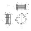
- FIG. 2a-2c show a ring stack 20 according to the invention with coupling elements 18, 19.
- the recesses / grooves 39 can be seen in the inner peripheral surface, which for receiving the guide rods 9 (see Figures 3 . 4a and 4b ) serve.
- FIG. 2b shows a cross-sectional view taken along the line BB in FIG. 2a in which the circumferential grooves 38, which serve to receive a sealing ring, are recognizable. Also visible are the separating gaps 37 between the individual annular disks.
- Figure 2c shows a corresponding cross-sectional view along the line AA in FIG. 2a ,
- the outer diameter of the coupling segments 18, 19 is equal to or greater than that of the annular discs. For handling reasons, however, it is preferred that the outer diameter is larger (s. FIGS. 2b and 2c ).
- the upper surface of the upper coupling element A and / or the lower surface of the lower coupling element B is not flat / flat but designed as a spring seat. In this way, the springs are directly absorbed and additionally protected against the fluid.
- the preferably provided spacer serves primarily as an assembly and guide aid as well as protection of the separator when entering the borehole, but is not mandatory. He does not contribute to the function of the separator itself. This is particularly important because the materials used have a lower abrasion and corrosion resistance and wear faster during operation of the delivery unit. However, since the spacer has no bearing / storage task and the ring stack is designed according to the invention so that it is self-centering, the function or the stability of the separator remains unaffected by the wear of the spacer.
- the spacer preferably consists of three components: two guide rings (7, 8 in Figures 3 . 3a . 4a and 4b ), the spacer strips (12 in FIG. 3a ) and the guide rods (9 in FIG. 3 . 3a . 4a and 4b ).
- the two guide rings 7, 8 are on the inner tube (delivery pipe 22). At their outer peripheral surfaces, they have incorporated three or more recesses / grooves, which serve to receive the guide rods 9. Directed longitudinally of the tube axis of the inner tube, these guide rods 9 receive the ring elements on the inner recesses of the rings. Guide rings 7, 8 and guide rods 9 together represent the radial distance between the ring elements and the inner tube 22.
- the spacer strips 12 are also secured to the outer peripheral surfaces of the guide rings, preferably via spot welding, and provide the longitudinal distance between the ferrules 1, 2nd that is, the length of the ring stack 20 a.
- the annular discs 30 are built together with the two coupling elements on the spacer. With the help of the flexurally elastic guide rods 9, the alignment and guiding of the ring elements takes place during assembly.
- the arranged on the top of the rings spacers 32 of the annular discs 30 can thus be quickly and easily aligned each other when stacking each other, so that the axial load introduction takes place in the axis of the three spacers 32. This avoids the edge loads which are critical for brittle-hard materials, and a three-point support at the desired support points is also achieved in the case of annular disks with deviations in shape.
- the guide rings 7, 8 and the spacer strips 12 are preferably made of steel, but it is also possible to use plastic guide rings.
- the guide rods are preferably not made of steel, but of plastic, preferably made of PEEK, to allow an elastic, sliding recording of the brittle-hard annular discs. If the plastic rods wear, so the separator remains stable due to the "self-centering" and the function is still guaranteed.
- the attachment of the ring stack on the inner tube (conveyor tube) by means of a clamping device (clamping set / clamping set).
- the clamping device preferably consists of clamping sleeves, compression springs, compression spring seats and clamping nuts.
- Task of the clamping set (1 to 6 in FIG. 3 . 4a and 4b ) is to brace the axially stacked ring elements in itself to fix the separating gap formed between the individual discs with a height preferably of 0.05-1 mm, more preferably 0.1-0.5 mm and the separator on the inner tube (delivery pipe) to attach.
- the compression springs (13 in FIG. 3 . 4a and 4b ) provide an elastic compensation and thus allow a bending deformation of the separator, which protects in particular during insertion into the borehole and against breakage in case of overload.
- the compression springs 13 are preferably selected from corrosion-resistant steel, coated steel or corrosion-resistant elastomer such as rubber or Viton.
- the clamping set for fastening the separating device on the inner tube is preferably designed as a three-part non-positive, releasable interference fit. It consists of the components clamping sleeve (1, 2 in Figures 3 . 4a and 4b ), Compression spring seat (3, 4 in Figures 3 . 4a and 4b ) and clamping nut (5, 6 in Figures 3 . 4a and 4b ).
- the clamping sets are preferably made of steel, more preferably made of corrosion-resistant steel.
- the clamping sleeves 1, 2 are cylindrical inside; on the outside, two areas can be distinguished: a thread (1a, 2a in FIGS. 4a and 4b ) and an outer conical wedge surface (1b, 2b in FIG FIGS. 4a and 4b ).
- the clamping nut engages the clamping sleeve via the thread.
- the tapered wedge surface is preferably slotted longitudinally to allow for larger clearance play and thus relatively large tolerances.
- the clamping sleeves can preferably be coated externally with copper for protection against contact corrosion.
- the compression spring seats (3, 4 in Figures 3 . 4a and 4b ) preferably have an inner conical clamping surface, inner guides for receiving the compression springs and an outer guide for receiving the outer cage (11 in Figures 3 and 3a ; 10 serves to accommodate the outer cage).
- the clamping takes place via the clamping nuts 5, 6.
- the axial clamping force clamping sleeve 1, 2 and compression spring seat 5, 6 are shifted into each other, wherein they deform elastically and generate high contact forces in the joints between the clamping element and the inner tube and thus cause the adhesion.
- the device is sealed by means of O-rings 15, 16 between inner tube and clamping nut, by means of O-rings 17 between the clamping nut and compression spring seat and by means of O-rings 14 between compression spring seat and coupling segment.
- a fixation on the threaded sleeve i. the transition between different conveyor equipment units, be selected.
- the separating device according to the invention is preferably against damage during installation and when starting the promotion by a freely permeable outer cage (11 in Figures 3 and 3a ) protected.
- This can for example be designed as a coarse mesh screen and preferably as a perforated plate.
- the material used is preferably steel.
- the outer surfaces of the clamping sets and the portions of the conveying tube, which are not protected by the brittle-hard rings and the joints / sleeve areas where the conveyor pipe is completed with other components to the drill string are preferably protected by one or more protective sheaths against wear.
- the liquid flow is indeed conducted from the delivery point directly through the stack of rings in the delivery pipe, without flow deflection.
- the lying outside of the separator areas are flown as a result of stray flux, as a result of inaccurate positioning of the separator to the conveyor or when the conveyor is further extended than the separator, so that it is the wear of the outside of the separator lying areas of the delivery tube comes.
- the wear is caused by abrasion / erosion by sand and rock particles as well as by corrosion.
- the corrosion occurs as a result of the treatment liquids used, such as HCl, H 2 SO 4 , HF and CaCl 2 / CaBr 2 , especially in conjunction with the occurring particle erosion, which prevents the formation of passivating surface layers.
- the wear protection of the abovementioned metallic areas outside the separating device takes place by means of a plastic coating, for example by means of a heat-shrinkable tube.
- a plastic coating for example by means of a heat-shrinkable tube.
- (powder) coatings or coatings by covering mats or foils, which are fixed for example by means of mechanical clamps, or by molded parts.
- the molded parts can be designed, for example, in the form of two half shells, for example made of polyolefin, which have been machined to size.
- the half shells can be connected via tongue and groove or by screwing.
- suitable spacers may be applied, e.g. can be realized as Gleitnoppen on the perforated plate.
- the materials for the plastic coating are preferably selected from the group of polyolefins, preferably polyethylene, polypropylene and poly (iso) butane, since these on the one hand have sufficient resistance to abrasion / erosion and corrosion and on the other hand can be applied as a shrink tube.
- polyolefins preferably polyethylene, polypropylene and poly (iso) butane
- Other possible materials for the plastic coatings or shrink tubing are PVDF, Viton, PVC and PTFE.
- FIG. 5 An embodiment of the shrink tube 21 is in FIG. 5 shown.
- SSiC coarse grained, sintered silicon carbide ceramic
- EPC fine-grained, sintered silicon carbide ceramic
- the experiments were carried out by means of a sandblasting machine.
- the blasting media used were four different proppants typically used in offshore drilling: (1) 100 mesh frac sand, (2) 16/20 mesh frac sand, (3) 20/40 mesh frac sand, (4) 20/40 Mesh Frac Sand High Strength.
- the jet pressure was 2 bar and the jet duration 2 hours, with the beam was applied quasi point-like at an angle of 90 ° to the surface. Depth and the width of the jet impression characterize the erosive wear (see Table 1).
- the experiments show that the sintered silicon carbide ceramics are significantly more resistant to erosive wear compared to conventional steels.
- EKasic ® C and EKasic® F show no measurable or even negligible erosive wear.
- Rods (approximately 3 x 4 x 25 mm) made of coarse-grained silicon carbide ceramic type EKasic ® C and fine-grained silicon carbide ceramic type EKasic ® F were subjected to a corrosion test.
- a ceramic ring stack separator was made and subjected to a flow through performance test to determine the pressure loss at various flow rates.
- the annular discs have an outer diameter of 130 mm and an inner diameter of 109 mm.
- the ring height is optionally 3, 5 and 8 mm.
- the lower side is concavely arched, the radius of curvature is 2000 mm.
- the gap height at the outside diameter is 0.25 or 0.45 mm.
- the annular discs are made of silicon carbide.
- the test device comprises an inner tube, a stack of annular discs and an outer cover.
- the inner tube has a diameter of 101 mm and a length of 300 mm. In the middle are located in the lateral surface four 90 ° offset openings (23 in FIG. 3 ), through which the pumped medium can flow into the inner tube.
- the inner tube thus corresponds to commonly used, commercially available devices.
- the annular disks are stacked around the inner pipe by means of a support structure formed of three rods guiding the annular disks on the inner side thereof so that the spacers are superimposed and a radial gap is formed.
- the total length of the test device is 300 mm.
- the separator thus comprises 38 to 105 discs. This corresponds to a free filter area of 5 to 16%.
- test device is covered by a perforated plate of thickness 2 mm.
- the square holes have a length of about 10 mm and are arranged at a distance of 15 mm regularly.
- the test was carried out by means of the in FIG. 6 performed construction shown.
- the test device is installed in a cylindrical housing, over the end faces of which water (density 1.0 g / cm 3 , dynamic viscosity 1 cP) is supplied at room temperature.
- the flow of the separator takes place via the perforated plate and the column on the outer diameter of the stacked annular discs.
- the drain is through the inner tube. The pressure loss between inlet and outlet at the housing is measured depending on the flow.
- ring stacks were subjected to a pressure test to simulate the effect of increased compressive stress on the separator.
- the ring disks were made according to Example 3, the stack each comprising 10 disks.
- the spacers were aligned one above the other.
- the load was carried out axially by means of a hydraulic press, wherein the force was applied continuously until the breakage of at least one of the annular discs.
- the example shows how a separator according to the invention is mounted on a conveyor tube according to Figures 3, 4a and 4b.
- the delivery pipe 22 has a length of 1200 mm and a minimum diameter of 90 mm. Halfway along the tube, there are four openings (offset by 90 °) in the lateral surface, through which the filtered medium can be directed into the interior of the tube. At the ends, the pipe has a connection area with an internal or an external thread (pup joints), with the help of which the pipe can be connected at the completion with upstream and downstream equipment of the drill string.
- the openings 23 of the conveying tube 22 are protected by the separating device according to the invention.
- the separating device comprises the annular gap filter (ring stack), coupling elements and the clamping or tensioning device, with the aid of which the annular gap filter is mechanically braced in itself, secured and secured on the pipe.
- the separator has a length of 570 mm and an outer diameter of 143 mm. It is arranged symmetrically to half the pipe length (center of the opening, center of the pipe).
- the annular discs are made as shown in Figures 1a-1f. They have an outer diameter of 130 mm and an inner diameter of 109 mm.
- the ring height is 5 mm.
- the lower side is concave.
- the radius the warpage is 2000 mm.
- the height of the ball sections is selected to be 0.4 mm, so that the gap height at the outer diameter is 0.25 mm.
- the washers are made of silicon carbide (EKasic ® F plus).
- the annular discs are stacked around the conveyor tube and aligned so that each forms a radial gap perpendicular to the longitudinal axis of the conveyor tube between the discs.
- the stacked washers are guided by the spacer.
- the ends of a guide rod 9 lie on both sides on guide rings 7, 8.
- the guide rings enclose the delivery pipe 22 and are pushed onto this.
- the ring stack (without coupling segments) has a total length of 351 mm and comprises 75 discs. This corresponds to a free filter area of 5%.
- the front end of the ring stack 20 form two ceramic coupling segments 18, 19 made of EKasic ® F plus. They have an outer diameter of 133 mm, an inner diameter of 109 mm and a height of 17 mm. On the outer circumference a groove for receiving a sealing ring is incorporated ( FIG. 2 ).
- the attachment on the conveyor tube is carried out by means of a clamping set according to Figures 3, 4a and 4b, which is formed of clamping sleeve, clamping nut and compression spring seat.
- the separator is covered by a perforated plate of thickness 2 mm.
- the square holes have a length of about 10 mm; they are regularly arranged at a distance of 5 mm.
Landscapes
- Chemical & Material Sciences (AREA)
- Geology (AREA)
- Life Sciences & Earth Sciences (AREA)
- Engineering & Computer Science (AREA)
- Chemical Kinetics & Catalysis (AREA)
- Mining & Mineral Resources (AREA)
- Fluid Mechanics (AREA)
- Environmental & Geological Engineering (AREA)
- Physics & Mathematics (AREA)
- General Life Sciences & Earth Sciences (AREA)
- Geochemistry & Mineralogy (AREA)
- Inorganic Chemistry (AREA)
- Ceramic Engineering (AREA)
- Dispersion Chemistry (AREA)
- Centrifugal Separators (AREA)
- Earth Drilling (AREA)
- Filtering Materials (AREA)
- Physical Or Chemical Processes And Apparatus (AREA)
- Separation Using Semi-Permeable Membranes (AREA)
Abstract
Description
- Die Erfindung betrifft eine neuartige Trennvorrichtung mit verbessertem Erosions- und Abrasionswiderstand, zum Einsatz für Durchflussvorrichtungen zur Förderung von Öl-, Wasser- und Gasgemischen oder deren Einzelkomponenten, mit deren Hilfe Feststoffe, wie Sand- und Gesteinspartikel von den zu fördernden Flüssigkeiten und Gasen abgetrennt werden können. Die Trennvorrichtung dient insbesondere dazu, den erosiven und abrasiven Abtrag der Förderausrüstung in Tiefbohrungen durch Sand- und Gesteinspartikel zu verhindern. Gleichzeitig ist die Trennvorrichtung korrosionsbeständig gegenüber Behandlungsflüssigkeiten.
- Zur Förderung von Flüssigkeiten und Gasen, wie Öl-, Wasser- und Gasgemischen oder deren Einzelkomponenten aus Gesteinsreservoires werden Bohrlochausrüstungen eingesetzt, die im Wesentlichen aus einem Förderrohr bestehen, um das Fördermedium von der äußeren Förderstelle in das innere Förderrohr zu leiten. Dabei kann es sich um ein perforiertes Rohr handeln oder um ein Rohr, das mit mindestens einer Öffnung versehen ist. Diese Öffnungen sind häufig mit einer geeigneten Vorrichtung, wie Schieber oder Ventil versehen, mit deren Hilfe der Einfluss des Fördermediums gesteuert werden kann. Dieses Förderrohr (inneres Rohr) wird im weiteren auch als Durchflussvorrichtung bezeichnet, häufig werden auch die Begriffe Schiebemuffe, sliding sleeve und sliding side door verwendet.
- Bei der Förderung ist es erforderlich, die Lagerstättenpartikel und gegebenenfalls künstlich eingebrachte oder durch Abrieb erzeugte Partikel vom Fördermedium zu trennen und vor dem Eintritt in das Förderrohr herauszufiltern.
- Üblicherweise werden für diese Aufgabe metallische Drahtgewebe oder metallische Drahtgitter verwendet. Eine Lösung mit Drahtgewebe ist in der
US 5,624,560 beschrieben. Diese Lösungen mit Drahtgeweben oder Drahtgittern werden noch von einer metallischen Stützstruktur getragen, um mechanisch stabil zu bleiben. Ein wesentlicher Nachteil dieser Konstruktion ist ihre geringe Beständigkeit gegenüber Verschleiß. Aufgrund der abrasiven bzw. erosiven Wirkung der mit hoher Fließgeschwindigkeit einfließenden Sand- und Gesteinspartikel werden die Filter zerstört und die Förderrohre, insbesondere an den Öffnungen und Ventilen, beschädigt. Gleichzeitig nimmt die Produktivität der Förderung ab, da nunmehr der Sand nicht mehr effektiv ausgefiltert sondern mit dem Fördermedium weitertransportiert wird. Ein weiteres Problem ist der durch den Einsatz von Behandlungsflüssigkeiten auftretende korrosive Verschleiß an den Filtern und Förderrohren. Dieser korrosive Verschleiß verstärkt wiederum den abrasiven Verschleiß. Behandlungsflüssigkeiten, wie beispielsweise Säuren, Laugen, Wasser oder Heißdampf, werden zur Reinigung der Trenn- und Durchflussvorrichtung eingesetzt und zur Stimulation des Bohrlochs. - Es ist erforderlich, die Beständigkeit der Bohrlochausrüstung gegen abrasiven bzw. erosiven Verschleiß zu verbessern sowie sicherzustellen, dass sie korrosiv nicht angegriffen wird.
- In der
US 2004/0050217 A1 undWO 2008/080402 A1 sind Lösungen beschreiben, bei denen anstelle der metallischen Spaltsiebe Trennvorrichtungen aus porösen permeablen Werkstoffen eingesetzt werden. Die porösen Filterwerkstoffe derUS 2004/0050217 A1 können metallisch, keramisch oder organisch sein, in derWO 2008/080402 A1 werden poröse keramische Werkstoffe eingesetzt. - Ein Problem der in diesen beiden Schriften beschriebenen Lösungen ist, dass Filter aus porösen Werkstoffen aufgrund ihrer schlechten mechanischen Eigenschaften zum Bruch durch Biegebelastung neigen. Die Biegebruchbelastbarkeit liegt in der Regel bei deutlich weniger als 30% derjenigen des entsprechenden dichten Werkstoffs und ist daher für die mechanischen Belastungen bei den Einsatzbedingungen in Gesteinsbohrungen nicht ausreichend.
- Ein weiteres Problem ist, dass die Abrasions- und Erosionsbeständigkeit von porösen keramischen Werkstoffen deutlich geringer ist als die von dichten keramischen Werkstoffen.
- Eine weitere Lösung mit einer Trennvorrichtung aus porösen Werkstoffen ist in der
WO 2004/099560 A1 beschrieben, die ebenfalls die oben beschriebenen Nachteile aufweist. In einer weiteren Ausführungsform (Seite 7, Zeile 24 - Seite 8, Zeile 2 und Anspruch 20) sieht dieWO 2004/099560 A1 vor, einen konventionellen Sandfilter außen zusätzlich durch eine Manschette aus erosionsbeständigen, dichten Ringen zu schützen, die an ihren oberen und unteren Oberflächen zusätzlich Rippen oder Grübchen haben. An den aufeinandergestapelten Ringen bildet sich ein gewundener Flüssigkeitskanal aus, an dessen Wänden sich die Energie des durchströmenden Mediums durch Aufprall verringert, so dass der Verschleiß des darunter liegenden, konventionellen Sandfilters reduziert wird. Vorzugsweise sind die Ringe aus Carbiden oder Nitriden wie Siliziumcarbid oder Wolframcarbid gebildet. Nachteilig bei dieser Lösung ist, dass der verbesserte Verschleißschutz mit einer Energiedissipation des strömenden Mediums einhergeht; die äußere Manschette wirkt nicht als Filter sondern als Strömungswiderstand, der die Förderleistung verschlechtert. Es wird nicht offenbart, wie die Manschette auf dem Förderrohr befestigt wird. - In der
US 5,249,626 wird ein zylindrischer Siebfilter vorgestellt, der eine Vielzahl von gestapelten, ringförmigen Filtersegmenten beinhaltet. Der Ringstapel wird durch mehrere Gewindestäbe mit Gewindemuttern oder auch Doppelmuttern aus Edelstahl jeweils am oberen und unteren Ende zusammengehalten. Die Trennung der Partikel erfolgt am variablen Ringspalt, der zwischen gegenüberliegenden Filtersegmenten ausgebildet ist. Die Ringe sind aus Kunststoff, bevorzugt aus glasverstärktem Polypropylen (Spalte 4, Z. 50-54). Die Gewindestäbe werden durch dafür vorgesehene Öffnungen in den Ringen geführt (Spalte 4, Z. 31-33). Diese Lösung lässt sich aus Keramiken nicht realisieren. Die Querschnittsübergänge sind kantig; die Filtersegmente haben ein typisches Kunststoff-Design. Die Abstandshalter sind flächig ausgebildet, Biegespannungen könnten so bei keramischen Ringen nicht ausgeglichen werden. Die starre Lagerung der Stützkonstruktion würde es bei keramischen Ringen zudem nicht gestatten, Verformungen aufzunehmen; dies ist aber bei der Einbringung des Filters in die Bohrung zwingend erforderlich. Weitere Nachteile des in derUS 5,249,626 beschriebenen Siebfilters aus glasverstärktem Polypropylen sind dessen unzureichende Erosions- und Abrasionsbeständigkeit sowie ungenügende Korrosionsbeständigkeit. - Der Erfindung liegt die Aufgabe zugrunde, unter Überwindung der Nachteile des Standes der Technik eine Trennvorrichtung für rohrförmige Durchflussvorrichtungen zur Abtrennung von Sand- und Gesteinspartikeln bei der Förderung von Flüssigkeiten oder Gasen aus Tief- oder Gesteinsbohrungen zur Verfügung zu stellen, die eine bessere Verschleiß- bzw. Abrasions- und Erosionsbeständigkeit und eine geringere Bruchneigung als die im Stand der Technik bekannten Trennvorrichtungen aufweist, und die zudem korrosionsbeständig gegenüber Behandlungsflüssigkeiten ist, und bei der die Förderleistung durch den Verschleißschutz nicht nachteilig beeinflusst wird, und die den bei der Förderung und insbesondere beim Einbau auftretenden Biegebelastungen standhalten kann.
- Die vorstehende Aufgabe wird erfindungsgemäß gelöst durch eine Trennvorrichtung gemäß Anspruch 1 sowie deren Verwendung gemäß Anspruch 21, Vorteilhafte und besonders zweckmäßige Ausgestaltungen des Anmeldungsgegenstandes sind in den Unteransprüchen angegeben.
- Gegenstand der Erfindung ist somit eine Trennvorrichtung für rohrförmige Durchflussvorrichtungen, die zur Förderung von Flüssigkeiten oder Gasen aus Gesteins- oder Tiefbohrungen dienen, wobei die Trennvorrichtung zur Abtrennung von Sand- und Gesteinspartikeln geeignet ist und umfasst:
- einen Ringstapel aus sprödharten ringförmigen Scheiben, wobei die Scheiben so gestapelt und verspannt sind, dass zwischen den einzelnen Scheiben jeweils ein Trennspalt zur Abtrennung von Sand- und Gesteinspartikeln vorhanden ist;
- ein Ankopplungselement an einem oder beiden Enden des Ringstapels;
- eine Klemmvorrichtung an einem oder beiden Enden des Ringstapels, welche es einerseits ermöglicht, die sprödharten Scheiben flexibel zu verspannen und andererseits den Ringstapel auf der rohrförmigen Durchflussvorrichtung variabel zu befestigen.
- Gegenstand der Erfindung ist ebenso die Verwendung der erfindungsgemäßen Trennvorrichtung zur Abtrennung von Sand- und Gesteinspartikeln bei einem Verfahren zur Förderung von Flüssigkeiten oder Gasen aus Gesteins-oder Tiefbohrungen mittels rohrförmigen Durchflussvorrichtungen.
- Die aus sprödharten ringförmigen Scheiben (im Folgenden auch als "Ringelemente" bezeichnet) aufgebaute Trennvorrichtung ist abrasions- bzw. erosions- und korrosionsbeständig und keramikgerecht bzw. sprödharten Werkstoffen gerecht konstruiert. Die Abtrennung der Partikel ist in direkter An- und Durchströmung gewährleistet, ohne dass die Strömung negativ durch Umlenkung oder Energiedissipation beeinflusst wird.
- Die Trennvorrichtung beinhaltet neben dem Stapel aus ringförmigen Scheiben eine Klemmvorrichtung (Klemmsatz), die es einerseits ermöglicht, die sprödharten Ringelemente flexibel zu verspannen und andererseits den Ringstapel auf dem Förderrohr variabel zu befestigen.
- Die Durchflussvorrichtung ist in ihrer Gesamtheit gegen Abrasion/Erosion geschützt, und zwar im Bereich des direkten Durchflusses, also dem Bereich der Öffnungen und Ventile des inneren Rohrs. Der Schutz erfolgt durch die Ringelemente. Vorzugsweise können auch die außerhalb dieses Bereiches liegenden Klemmsätze, Rohrabschnitte und Verbindungsstellen geschützt sein.
- Die rohrförmigen Durchflussvorrichtungen können verschiedene Querschnittsformen aufweisen, wobei eine runde Querschnittsform bevorzugt ist. Ferner können die rohrförmigen Durchflussvorrichtungen auch über die Länge wechselnde Querschnittsflächen besitzen.
- Die komplette Trennvorrichtung ist keramikgerecht bzw. sprödharten Werkstoffen gerecht montiert, Verformungen können aufgenommen werden, ohne dass die Gefahr eines Bruches der Ringelemente aus dem sprödharten Werkstoff besteht.
- Die federnde Lagerung des Ringstapels ermöglicht, dass der Ringstapel Biegungen des inneren Rohrs ausgleichen kann. Biegungen von 3° und mehr auf 30 m können ohne Schwierigkeiten ausgeglichen werden. Die federnde Lagerung wird einerseits erreicht durch die Klemmsätze und Druckfedern, andererseits durch die bevorzugte konkave Ausformung des Ringbodens und die auf dem Ringboden bevorzugt angebrachten, die Abstandshalter aufnehmenden Vertiefungen, die insgesamt zu einer Beweglichkeit des Systems führen, so dass Biegungen ausgeglichen werden können.
- Der Druckverlust der erfindungsgemäßen Trennvorrichtung ist vernachlässigbar gering und die erfindungsgemäße Trennvorrichtung wird laminar durchströmt (siehe Beispiel 3), so dass die Förderleistung nicht nachteilig beeinflusst wird.
- Die Trennvorrichtung ist unter jeder Bohrlochablenkung einsetzbar, sowohl im horizontalen als auch im vertikalen Bohrloch und auch unter jeder anderen Bohrlochneigung, beispielsweise unter einer Bohrlohneigung von 60°. Dies ist ein Vorteil gegenüber den herkömmlich eingesetzten metallischen Drahtgittern.
- Die Verbindung des Ringstapels mit der Durchflussvorrichtung, also dem inneren Förderrohr ist so konstruiert, dass die Durchflussvorrichtung in der bevorzugten Ausführungsform nicht verändert wird, d.h. es ist nicht erforderlich, das im Handel erhältliche innere Rohr zur Montage der erfindungsgemäße Trennvorrichtung zu verändern, beispielsweise mechanisch zu bearbeiten wie etwa durch Drehen, Fräsen oder Bohren oder über thermische Verfahren wie beispielsweise Schweißen oder auch durch Kleben mit der Trennvorrichtung zu verbinden.
- Ein weiterer Vorteil ist, dass sich die abzutrennenden Sand- und Gesteinspartikel an den stabilen sprödharten Ringelementen als sogenannter sekundärer Filterkuchen (secondary gravel pack) aufbauen können. Die Stabilität dieses sekundären Filterkuchens wird durch die erfindungsgemäße Trennvorrichtung begünstigt, was zu einer Erhöhung der Bohrlochintegrität führt.
- Ein weiterer Vorteil ist, dass die erfindungsgemäße Trennvorrichtung keine Stützkonstruktion benötigt wie die Kunststoff-Filtersegmente in der
US 5,249,626 oder die metallischen Drahtgitter derUS 5,624,560 . - Die Erfindung wird anhand der Zeichnungen näher erläutert. Hierbei zeigen
-
Figuren 1a-1f verschiedene Ansichten einer erfindungsgemäßen ringförmigen Scheibe; -
Figuren 2a-2c schematisch verschiedene Ansichten eines Ringstapels mit Ankopplungselementen; -
Figur 3 eine Durchflussvorrichtung mit erfindungsgemäßer Trennvorrichtung einschließlich Außenkäfig zur Abdeckung der Trennvorrichtung; -
Figur 3a eine Querschnittsansicht A-A bezüglichFigur 3 ; -
Figuren 4a und 4b Klemmvorrichtungen zum Verspannen des Ringstapels und zur Befestigung des Ringstapels auf der rohrförmigen Durchflussvorrichtung; -
Figur 5 schematische Darstellung einer Schutzummantelung von Klemmvorrichtungen, außerhalb des verschleißbeständigen Ringstapels liegendem Abschnitt des Förderrohrs und Muffenbereich; und -
Figur 6 schematisch den Testaufbau für einen Durchfluss-Leistungstest. - Die erfindungsgemäße Trennvorrichtung umfasst sprödharte ringförmige Scheiben, die einfach und wirtschaftlich zu fertigen sind. Die Herstellung dieser ringförmigen Scheiben ist mittels pulvermetallurgischer oder keramischer Verfahren in einer automatisierten Mengenfertigung möglich. Die ringförmigen Scheiben können im so genannten Net-Shape-Prozess, bei dem die Ringscheiben aus Pulvern endkonturnah gepresst werden, hergestellt werden. Eine aufwändige mechanische Bearbeitung der Ringscheiben ist nicht erforderlich. Die bei einem Sinterprozess teilweise nicht vermeidbaren Form- und Maßabweichungen bei den einzelnen Ringscheiben sind bei einem erfindungsgemäßen Aufbau der Trennvorrichtung tolerierbar.
- Die in der Trennvorrichtung eingesetzten ringförmigen Scheiben sind in den
Figuren 1a-1f dargestellt. Sie sind aus einem sprödharten Werkstoff, vorzugsweise einem keramischen Werkstoff gefertigt, der abrasions-/erosionsbestän-dig ist gegen die Sand- und Gesteinspartikel sowie korrosionsbeständig gegen die Fördermedien und die zur Reinigung verwendeten Medien wie beispielsweise Säuren. - Die Abtrennung der Sand- und Gesteinspartikel erfolgt an einem radialen, vorzugsweise sich verjüngenden Spalt, der sich zwischen zwei aufeinanderliegenden, verspannten Ringelementen bildet. Die Ringelemente sind keramikgerecht bzw. sprödharten Werkstoffen gerecht konstruiert: Querschnittsübergänge sind ohne Kerben ausgeführt, die Ausbildung von Biegespannungen wird konstruktiv vermieden oder ausgeglichen.
- Der Innendurchmesser der ringförmigen Scheiben ist größer als der Durchmesser des inneren Rohres (Förderrohr) zu wählen, die ringförmigen Scheiben liegen auf dem inneren Rohr nicht auf. So wird gewährleistet, dass die beim Einbringen ins Bohrloch auftretende Durchbiegung über die Konstruktion des Ringstapels aufgenommen werden kann und ein Bruch der keramischen Elemente vermieden wird.
- Die Höhe der ringförmigen Scheiben ist abhängig von der geforderten Durchflussrate.
- Die
Figuren 1a-1f zeigen die Grundform einer erfindungsgemäßen ringförmigen Scheibe 30, die auf ihrer Oberseite 31 mindestens drei über den Kreisumfang der Scheiben gleichmäßig verteilte Abstandshalter 32 aufweist, mit deren Hilfe die Höhe des Trennspaltes (Spaltweite) eingestellt wird. Wie aus der Seitenansicht gemäßFigur 1d und der vergrößerten Schnittansicht gemäßFigur 1e entlang der Linie B-B inFigur 1a ersichtlich, sind die Abstandshalter 32 vorzugsweise in Form von Kugelabschnitten ausgebildet, um einen Punktkontakt zwischen gegenüberliegenden ringförmigen Scheiben 30 zu erzielen und flächige Kontakte zu vermeiden. - Es ist aber auch möglich, dass es zwischen gegenüberliegenden ringförmigen Scheiben einen Linienkontakt oder auch einen Flächenkontakt gibt. Ein Linienkontakt wird beispielsweise erhalten, wenn die Oberseiten der ringförmigen Scheiben eine wellenförmige Struktur aufweisen. Ein Flächenkontakt kann beispielsweise über elliptische Plateaus erreicht werden. Es sind aber auch andere Ausformungen möglich. Beim Aufeinanderstapeln werden die einzelnen Abstandshalter im Stapel fluchtend übereinander positioniert. Die Abstandshalter sind keine separat aufgebrachten Elemente, sie werden direkt bei der Herstellung der ringförmigen Scheiben ausgebildet.
-
Figur 1b zeigt eine Schnittansicht entlang der Linie A-A inFigur 1a . Eine vergrößerte Darstellung des Bereichs X durch einen Abstandshalter 32 ist inFigur 1c gezeigt. Eine perspektivische Ansicht einer erfindungsgemäßen ringförmigen Scheibe ist inFigur 1f dargestellt. - Die ringförmigen Scheiben 30 haben an ihrer inneren Umfangsfläche vorzugsweise wenigstens drei Aussparungen/Nuten 33 , die der Aufnahme von Führungsstäben 9 dienen. Anhand dieser Führungsstäbe 9 können die Ringe beim Einbau leichter fluchtend übereinander positioniert werden. Die Aussparungen sind vorzugsweise abgerundet ausgeformt, wie in
Figuren 1a und 1f gezeigt. - Die Oberseite 31 der ringförmigen Scheiben 30 kann im rechten Winkel zur Scheibenachse oder nach innen abfallend oder nach außen abfallend mit ebener oder gekrümmter Fläche ausgeführt sein. Eine nach innen abfallende Ausführung ist vorteilhaft in Bezug auf eine verminderte Neigung zum Zusetzen der Trennvorrichtung.
- Die Unterseite 34 (Ringboden) der ringförmigen Scheiben 30 ist nach außen oder nach innen abfallend, vorzugsweise nach innen abfallend, weiter vorzugsweise ist sie konkav ausgebildet, wie in
Figur 1c gezeigt. Die konkave Ausformung ist auf den Ringboden als ganzes zu verstehen. Hier ist der Ringboden mit einem Radius R ausgeführt. Durch die konkave Ausformung können die einzelnen ringförmigen Scheiben einer Biegebelastung leicht ausweichen. Durch die konkave Ausformung des Ringbodens in Kombination mit der Drei-Punkt-Auflage können mögliche Form- und Maßabweichungen leicht ausgeglichen werden. - Außerdem verhindert die nach innen abfallende Form der Unterseite eine dezentrale Verschiebung der einzelnen Ringe im Stapel. Diese radiale Selbstzentrierung des Ringstapels ermöglicht die Verwendung der Trennvorrichtung ohne Stützkonstruktion, die bei metallischen Ringen oder Kunststoffringen in der Regel notwendig und üblich ist, siehe beispielsweise in der
US 5,249,626 oder in derUS 5,624,560 . - Auf der Unterseite 34 der Ringe gibt es vorzugsweise zusätzlich mindestens drei Vertiefungen 35 , in denen die Abstandshalter 32 der gegenüberliegenden Oberseite des nächsten Ringsegmentes positioniert werden können. Die Anzahl und der Abstand der Vertiefungen 35 richten sich nach Anzahl und Abstand der Abstandshalter 32 auf der Ringoberseite 31.
- Die eingebrachten Vertiefungen 35 dienen als Verdrehsicherung der Ringe und unterstützen die Selbstzentrierung der Ringe im Stapel. Bei den Vertiefungen handelt es sich vorzugsweise um parallel zum Radius R verschobene Flächen (s.
Figur 1c ). So wird auch hier ein Punktkontakt zu den Abstandshaltern gewährleistet und über die Drei-Punkt-Auflage werden mögliche Form- und Maßabweichungen ausgeglichen. Die Vertiefungen 35 können auch in Form von Kugel- oder Zylinderabschnitten ausgebildet sein. Auch eine abgerundete Trapezform oder eine wellenförmige Struktur ist möglich. - Die Querschnittsform der ringförmigen Scheiben ist bevorzugt nicht rechteckig und nicht trapezförmig aufgrund der vorzugsweise konkav gewölbten Flächen. Sie hat außerdem vorzugsweise keine scharfen Kanten und Querschnittsübergänge.
- In einer bevorzugten Ausführungsform sind die Außenkonturen 36 der ringförmigen Scheiben 30 mit einer Fase ausgeführt, wie in
Figur 1c veranschaulicht. Gemäß einer anderen bevorzugten Ausführungsform können die Kanten auch verrundet sein. Dies stellt einen noch besseren Schutz der Kanten vor der für sprödharte Werkstoffe kritischen Kantenbelastung dar. - Die Umfangsflächen (Mantelflächen) der ringförmigen Scheiben sind bevorzugt zylindrisch (eben). Es ist aber auch möglich, die Umfangsflächen nach außen beispielsweise konvex auszuformen, um eine bessere Anströmung zu erzielen.
- Die radiale Wandstärke der ringförmigen Scheiben beträgt vorzugsweise mindestens 2,5 mm, weiter vorzugsweise mindestens 5 mm. Die Höhe der Scheiben beträgt vorzugsweise 1 bis 20 mm, weiter vorzugsweise 1 bis 10 mm.
- Der Außendurchmesser der ringförmigen Scheiben ist kleiner als der innere Durchmesser des Bohrlochs beziehungsweise als der Innendurchmesser des Bohrlochfutterrohres. Er beträgt üblicherweise 50-200 mm.
- Die Spaltweite der Trennspalte 37 wird abhängig von der zu trennenden Sandfraktion gewählt. Am Außendurchmesser ist die Spaltweite am kleinsten, um ein Zusetzen des Ringspaltes zu vermeiden. Die Spaltweite wird eingestellt über die Höhe der Abstandshalter auf der Ringoberseite, die Tiefe der Vertiefungen auf der Ringunterseite und die Form der Ringunterseite, z.B. über den Radius der bevorzugt konkav gewölbten Fläche. Die gewählte Spaltgeometrie gewährleistet, dass die Strömungsvorgänge im Spalt laminar sind, und dass der Druckverlust zwischen Außen- und Innendurchmesser gering ist.
- Die Trennvorrichtung ist rückspülbar. Durch flüssige Behandlungsmedien kann der Filterkuchen gelockert und damit die Förderleistung wieder gesteigert werden.
- Der sprödharte Werkstoff der ringförmigen Scheiben ist vorzugsweise gewählt aus oxidischen und nichtoxidischen keramischen Werkstoffen, Mischkeramiken aus diesen Werkstoffen, keramischen Werkstoffen mit Zusatz von Sekundärphasen, Mischwerkstoffen mit Anteilen von keramischen Hartstoffen und mit metallischer Bindephase, ausscheidungsgehärteten Gusswerkstoffen, pulvermetallurgischen Werkstoffen mit in-situ gebildeten Hartstoffphasen und lang- und / oder kurzfaserverstärkten Keramikwerkstoffen.
- Beispiele für oxidische keramische Werkstoffe sind Al2O3, ZrO2, Mullit, Spinell und Mischoxide. Beispiele für nichtoxidische keramische Werkstoffe sind SiC, B4C, TiB2 und Si3N4. Keramische Hartstoffe sind beispielsweise Carbide und Boride. Beispiele für Mischwerkstoffe mit metallischer Bindephase sind WC-Co, TiC-Fe und TiB2-FeNiCr. Beispiele für in-situ gebildet Hartstoffphasen sind Chrom-Carbide. Ein Beispiel für faserverstärkte Keramikwerkstoffe ist C-SiC.
- Die oben genannten Werkstoffe zeichnen sich dadurch aus, dass sie härter sind als die typischerweise vorkommenden Gesteinspartikel, das heißt die HV-oder HRC-Härtewerte dieser Werkstoffe liegen über den entsprechenden Werten des umgebenden Gesteins. Alle diese Werkstoffe zeichnen sich gleichzeitig dadurch aus, dass sie eine größere Sprödigkeit als typische ungehärtete Stahllegierungen haben. In diesem Sinne werden diese Werkstoffe hierin als "sprödhart" bezeichnet.
- Vorzugsweise werden Werkstoffe mit einer Dichte von mindestens 90%, weiter vorzugsweise mindestens 95%, der theoretischen Dichte eingesetzt, um möglichst hohe Härtewerte und hohe Abrasions- und Korrosionswiderstände zu erzielen. Vorzugsweise werden als sprödharter Werkstoff gesintertes Siliciumcarbid (SSiC) oder Borcarbid eingesetzt. Diese Werkstoffe sind nicht nur abrasionsbeständig, sondern auch korrosionsbeständig gegenüber den üblicherweise für das Freispülen der Trennvorrichtung und die Stimulation des Bohrlochs verwendeten Behandlungsflüssigkeiten wie Säuren (z.B. HCl). Laugen (z.B. NaOH) oder auch Wasserdampf.
- Besonders geeignet sind beispielsweise SSiC-Werkstoffe mit feinkörnigem Gefüge (mittlere Korngröße < 5 µm), wie sie beispielsweise unter dem Namen EKasic® F und EKasic® F plus von ESK Ceramics GmbH & Co. KG vertreiben werden. Außerdem können aber auch grobkörnige SSiC-Werkstoffe eingesetzt werden, beispielsweise mit bimodalem Gefüge, wobei vorzugsweise 50 bis 90 Vol.-% der Korngrößenverteilung aus prismatischen, plättchenförmigen SiC-Kristalliten einer Länge von 100 bis 1500 µm besteht und 10 bis 50 Vol.-% aus prismatischen, plättchenförmigen SiC-Kristalliten einer Länge von 5 bis weniger als 100 µm (EKasic® C von ESK Ceramics GmbH & Co. KG).
- Die Ankopplungselemente 18, 19 (siehe
Figuren 2a-2c ,3 ,4a und 4b ) bilden die stirnseitigen, seitlichen Abschlüsse des Ringstapels über die die Trennvorrichtung an der Klemmvorrichtung (den Klemmsätzen/Spannsätzen) ankoppelt. Sie sind so gestaltet, dass die Spannkräfte gleichmäßig auf den Ringstapel übertragen werden. - Die Ankopplungselemente sind vorzugsweise aus demselben Werkstoff wie die Ringe hergestellt. Alternativ können aber auch korrosionsbeständige Stähle und Kunststoffe wie beispielsweise Fluorelastomere oder PEEK (Polyetherketon) eingesetzt werden.
- Die obere Fläche des oberen Ankopplungselementes A (18 in
Figur 4a ), die zur Klemmvorrichtung gerichtet ist, hat vorzugsweise eine ebene/flache Oberfläche. Die zur Trennvorrichtung gerichtete Fläche, also die Unterseite des Ankopplungssegmentes A, ist vorzugsweise mit Radius ausgeführt, d.h. wie die Ringelemente vorzugsweise konkav. Die innere Umfangsfläche hat vorzugsweise drei oder mehr Aussparungen/Nuten (39 inFigur 2a ) zur Aufnahme der Führungsstäbe 9. Die äußere Umfangsfläche hat vorzugsweise eine umlaufende Nut (38 inFigur 2b und 2c ) zur Aufnahme eines Dichtrings (O-Ring) (14 inFiguren 3 und4a ). - Die untere Fläche des unteren Ankopplungselementes B (19 in
Figur 4b ), die zur Klemmvorrichtung gerichtet ist, hat vorzugsweise eine ebene/flache Oberfläche. Die zur Trennvorrichtung gerichtete Fläche, also die Oberseite des Ankopplungssegmentes B, hat vorzugsweise mindestens drei über den Kreisumfang der Scheiben gleichmäßig verteilte Abstandshalter. Die innere Umfangsfläche hat vorzugsweise drei oder mehr Aussparungen/Nuten (39 inFigur 2a ) zur Aufnahme der Führungsstäbe 9. Die äußere Umfangsfläche hat vorzugsweise eine umlaufende Nut (38 inFiguren 2b und 2c ) zur Aufnahme eines Dichtrings (O-Ring) (14 inFiguren 3 und4b ). - Die Toleranzen der beiden Ankopplungssegmente sind enger gewählt als die der Ringscheiben, um die sprödharten Komponenten optimal an die metallischen Komponenten des Klemmsatzes anzukoppeln; im Gegensatz zu den unbearbeiteten (as-sintered) Ringscheiben müssen die Ankopplungssegmente mechanisch bearbeitet werden.
- Die
Figuren 2a-2c zeigen einen erfindungsgemäßen Ringstapel 20 mit Ankopplungselementen 18, 19. In der Draufsicht gemäßFigur 2a sind die Aussparungen/Nuten 39 in der inneren Umfangsfläche zu erkennen, die zur Aufnahme der Führungsstäbe 9 (sieheFiguren 3 ,4a und 4b ) dienen. -
Figur 2b zeigt eine Querschnittsansicht entlang der Linie B-B inFigur 2a , worin die umlaufenden Nuten 38, welche zur Aufnahme eines Dichtrings dienen, erkennbar sind. Ebenfalls erkennbar sind die Trennspalten 37 zwischen den einzelnen Ringscheiben.Figur 2c zeigt eine entsprechende Querschnittsansicht entlang der Linie A-A inFigur 2a . - Der Außendurchmesser der Ankopplungssegmente 18, 19 ist gleich oder größer als derjenige der Ringscheiben. Aus Handhabungsgründen ist es jedoch bevorzugt, dass der Außendurchmesser größer ist (s.
Figuren 2b und 2c ). - In einer alternativen Ausführungsform ist die obere Fläche des oberen Ankopplungselementes A und/oder die untere Fläche des unteren Ankopplungselementes B nicht eben/flach sondern als Federsitz ausgebildet. Auf diese Weise werden die Druckfedern direkt aufgenommen und zusätzlich gegen das Fördermedium geschützt.
- Der vorzugsweise vorgesehene Distanzhalter dient vor allem als Montage- und Führungshilfe sowie als Schutz der Trennvorrichtung beim Einlassen ins Bohrloch, ist aber nicht zwingend erforderlich. Er trägt zur Funktion der Trennvorrichtung selbst nicht bei. Dies ist besonders deshalb wichtig, da die eingesetzten Materialien eine geringere Abrasions- und Korrosionsbeständigkeit aufweisen und beim Betrieb der Fördereinheit schneller verschleißen. Da der Distanzhalter jedoch keine tragende/lagernde Aufgabe besitzt und der Ringstapel erfindungsgemäß so gestaltet ist, dass er selbstzentrierend ist, bleibt die Funktion beziehungsweise die Stabilität der Trennvorrichtung durch den Verschleiß des Distanzhalters unbeeinflusst.
- Der Distanzhalter besteht bevorzugt aus drei Komponenten: zwei Führungsringen (7, 8 in
Figuren 3 ,3a ,4a und 4b ), den Abstandsleisten (12 inFigur 3a ) und den Führungsstäben (9 inFigur 3 ,3a ,4a und 4b ). - Die beiden Führungsringe 7, 8 liegen auf dem inneren Rohr (Förderrohr 22) auf. An ihren äußeren Umfangsflächen haben sie drei oder mehr Aussparungen/Nuten eingearbeitet, die zur Aufnahme der Führungsstäbe 9 dienen. Längs zur Rohrachse des inneren Rohrs gerichtet nehmen diese Führungsstäbe 9 die Ringelemente an den inneren Aussparungen der Ringe auf. Führungsringe 7, 8 und Führungsstäbe 9 stellen zusammen den radialen Abstand zwischen den Ringelementen und dem inneren Rohr 22 dar. Die Abstandsleisten 12 sind ebenfalls an den äußeren Umfangsflächen der Führungsringe befestigt, vorzugsweise über Punktschweißen, und stellen den längsseitigen Abstand zwischen den Klemmhülsen 1, 2, das heißt die Länge des Ringstapels 20 ein.
- Bei der Montage werden die ringförmigen Scheiben 30 zusammen mit den beiden Ankopplungselementen auf dem Distanzhalter aufgebaut. Mit Hilfe der biegeelastischen Führungsstäbe 9 erfolgt die Ausrichtung und Führung der Ringelemente bei der Montage. Die auf der Oberseite der Ringe angeordneten Abstandshalter 32 der ringförmigen Scheiben 30 können so beim Aufeinanderstapeln schnell und einfach jeweils übereinander ausgerichtet werden, so dass die axiale Lasteinleitung in der Achse der drei Abstandshalter 32 erfolgt. Dadurch werden die für sprödharte Werkstoffe kritischen Kantenbelastungen vermieden, und es wird auch bei Ringscheiben mit Formabweichungen eine Drei-Punkt-Auflage an den gewünschten Auflagepunkten erreicht.
- Die Führungsringe 7, 8 sowie die Abstandsleisten 12 sind vorzugsweise aus Stahl, es ist aber auch möglich, Führungsringe aus Kunststoff zu verwenden.
- Die Führungsstäbe sind vorzugsweise nicht aus Stahl, sondern aus Kunststoff, vorzugsweise aus PEEK gefertigt, um eine elastische, gleitende Aufnahme der sprödharten Ringscheiben zu ermöglichen. Sollten die Kunststoffstäbe verschleißen, so bleibt die Trennvorrichtung aufgrund der "Selbstzentrierung" in sich stabil und die Funktion ist weiterhin gewährleistet.
- Vorzugsweise erfolgt die Befestigung des Ringstapels auf dem inneren Rohr (Förderrohr) mittels einer Klemmvorrichtung (Klemmsatz/Spannsatz).
- Die Klemmvorrichtung besteht vorzugsweise aus Klemmhülsen, Druckfedern, Druckfedersitzen und Klemm-Muttern.
- Aufgabe des Klemmsatzes (1 bis 6 in
Figur 3 ,4a und 4b ) ist es, die axial aufeinander gestapelten Ringelemente in sich zu verspannen, den zwischen den einzelnen Scheiben gebildeten Trennspalt mit einer Höhe vorzugsweise von 0,05-1 mm, weiter vorzugsweise 0,1-0,5 mm zu fixieren und die Trennvorrichtung auf dem inneren Rohr (Förderrohr) zu befestigen. - Mit Hilfe des Klemmsatzes und der Druckfedern 13 wird der Ringstapel flexibel verspannt, d.h. Verformungen (Biegungen) können aufgenommen werden, und variabel auf dem inneren Rohr befestigt. Es lassen sich Trennvorrichtungen beliebiger Länge zusammenstellen und die Trennvorrichtung kann auf Förderrohren unterschiedlicher Bauart montiert werden.
- Die Druckfedern (13 in
Figur 3 ,4a und 4b ) sorgen für eine elastische Kompensation und erlauben so eine Biegeverformung der Trennvorrichtung, die insbesondere beim Einbringen ins Bohrloch und gegen Bruch bei Überlast schützt. - Die Druckfedern 13 sind vorzugsweise aus korrosionsbeständigem Stahl, beschichtetem Stahl oder korrosionsbeständigem Elastomer wie beispielsweise Gummi oder Viton gewählt.
- Der Klemmsatz zur Befestigung der Trennvorrichtung am inneren Rohr wird vorzugsweise als dreiteiliger kraftschlüssiger, lösbarer Pressverband ausgeführt. Er besteht aus den Komponenten Klemmhülse (1, 2 in
Figuren 3 ,4a und 4b ), Druckfedersitz (3, 4 inFiguren 3 ,4a und 4b ) und Klemm-Mutter (5, 6 inFiguren 3 ,4a und 4b ). - Die Klemmsätze sind vorzugsweise aus Stahl, weiter vorzugsweise aus korrosionsbeständigem Stahl, gefertigt.
- Die Klemmhülsen 1, 2 sind innen zylindrisch; außen lassen sich zwei Bereiche unterscheiden: ein Gewinde (1a, 2a in
Figuren 4a und 4b ) und eine äußere, kegelige Keilfläche (1b, 2b inFiguren 4a und 4b ). Über das Gewinde greift die Klemm-Mutter an die Klemmhülse an. Die kegelige Keilfläche ist vorzugsweise in Längsrichtung geschlitzt, um größere Passungsspiele und somit relativ große Toleranzen zuzulassen. Die Klemmhülsen können vorzugsweise außen mit Kupfer beschichtet werden zum Schutz vor Kontaktkorrosion. - Die Druckfedersitze (3, 4 in
Figuren 3 ,4a und 4b ) haben vorzugsweise eine innere konische Spannfläche, Innenführungen zur Aufnahme der Druckfedern und eine äußere Führung zur Aufnahme des Außenkäfigs (11 inFiguren 3 und3a ; 10 dient zur Aufnahme des Außenkäfigs). - Das Spannen erfolgt über die Klemm-Muttern 5, 6. Durch die axiale Spannkraft werden Klemmhülse 1, 2 und Druckfedersitz 5, 6 ineinander verschoben, wobei sie sich elastisch verformen und in den Fugen zwischen dem Spannelement und dem inneren Rohr hohe Anpresskräfte erzeugen und damit den Kraftschluss bewirken.
- Die Vorrichtung wird mittels O-Ringen 15, 16 zwischen innerem Rohr und Klemm-Mutter, mittels O-Ringen 17 zwischen Klemm-Mutter und Druckfedersitz sowie mittels O-Ringen 14 zwischen Druckfedersitz und Ankopplungssegment abgedichtet.
- Alternative Befestigungsarten zu Gewinde und Klemm-Mutter stellen die Kombinationen aus Nut und Sicherungsring sowie Senkbohrung und Madenschraube dar. Auch eine Befestigung mittels Schweißen ist möglich.
- Außerdem ist es denkbar, alternativ zur beidseitigen biegelastischen Aufnahme eine einseitige zu wählen. Dies ist beispielsweise möglich, wenn die Verspannung gegen einen festen Anschlag auf dem Förderrohr erfolgt. Dieser Anschlag kann alternativ als ebene Fläche oder als Federsitz ausgebildet sein.
- Alternativ zur Befestigung auf dem Förderrohr kann auch eine Fixierung auf den Gewindemuffen, d.h. dem Übergang zwischen verschiedenen Förderequipmenteinheiten, gewählt werden.
- Die erfindungsgemäße Trennvorrichtung ist vorzugsweise gegen Beschädigungen beim Einbau sowie beim Anfahren der Förderung durch einen frei durchströmbaren Außenkäfig (11 in
Figuren 3 und3a ) geschützt. - Dieser kann beispielsweise als grobmaschiges Sieb und vorzugsweise als Lochblech ausgeführt sein. Als Material wird vorzugsweise Stahl verwendet.
- Alternativ ist aber auch der Einsatz eines beim Einbau schützenden, nicht durchströmbaren Polymermantels denkbar, der dann beim Anfahren der Förderung durch die Abrasion zersetzt wird und somit die Trennvorrichtung freigibt.
- Die außen liegenden Flächen der Klemmsätze und die Abschnitte des Förderrohres, die nicht durch die sprödharten Ringe geschützt sind sowie die Verbindungsstellen/Muffenbereiche, an denen das Förderrohr mit anderen Komponenten zum Bohrstrang komplettiert wird, werden vorzugsweise durch eine oder mehrere Schutzummantelungen gegen Verschleiß geschützt. Grundsätzlich wird der Flüssigkeitsstrom zwar von der Förderstelle direkt durch den Ringstapel in das Förderrohr geführt, ohne Strömungsumlenkung. Es ist jedoch nicht vermeidbar, dass auch die außerhalb der Trennvorrichtung liegenden Bereiche angeströmt werden als Folge von Streuflüssen, als Folge einer ungenauen Positionierung der Trennvorrichtung zur Förderstelle oder wenn die Förderstelle weiter ausgedehnt ist als die Trennvorrichtung, so dass es zum Verschleiß der außerhalb der Trennvorrichtung liegenden Bereiche des Förderrohrs kommt. Der Verschleiß wird hervorgerufen durch Abrasion / Erosion durch Sand- und Gesteinspartikel sowie durch Korrosion. Die Korrosion tritt als Folge der verwendeten Behandlungsflüssigkeiten auf, wie beispielsweise HCl, H2SO4, HF und CaCl2/CaBr2, vor allem in Verbindung mit der auftretenden Partikelerosion, die die Ausbildung von passivierenden Oberflächenschichten verhindert.
- Vorzugsweise erfolgt der Verschleißschutz der oben genannten außerhalb der Trennvorrichtung liegenden metallischen Bereiche mittels eines Kunststoffüberzuges, beispielsweise mittels eines Schrumpfschlauchs. Es ist jedoch auch möglich, den Verschleißschutz durch (Pulver-)beschichtungen oder Lackierungen zu erreichen, durch Abdeckmatten oder -folien, die beispielsweise mittels mechanischer Klemmen fixiert werden, oder auch durch Formteile. Die Formteile können beispielsweise in Form von zwei auf Maß bearbeitete Halbschalen, beispielsweise aus Polyolefin, gestaltet sein. Die Halbschalen können über Nut und Feder verbunden werden oder auch durch Verschraubung.
- Um Beschädigungen der Schutzummantelung beim Einbau zu verhindern, können geeignete Abstandshalter angebracht werden, die z.B. als Gleitnoppen auf dem Lochblech realisiert werden können.
- Die Materialien für den Kunststoffüberzug werden vorzugsweise aus der Stoffgruppe der Polyolefine, bevorzugt Polyethylen, Polypropylen und Poly(iso)butylan, gewählt, da diese einerseits einen ausreichenden Widerstand gegen Abrasion / Erosion und Korrosion besitzen und sich andererseits als Schrumpfschlauch applizieren lassen. Andere mögliche Materialien für die Kunststoffüberzüge oder Schrumpfschläuche sind PVDF, Viton, PVC und PTFE.
- Die Verwendung eines Schrumpfschlauchs hat gegenüber anderen Lösungen folgende Vorteile:
- Es lassen sich dichte, nicht permeable Überzüge realisieren, eine Funktionstrennung durch Beschichtung mit verschiedenen Schrumpfschlauchmaterialien ist möglich. So könnte beispielsweise außen ein Material mit hohem Erosionswiderstand und innen ein Material mit hohem Korrosionswiderstand aufgebracht werden.
- Die Verbindung mit den zu schützenden Bereichen ist formschlüssig. Förder- oder Reinigungsmedien können nicht unter den Überzug "kriechen". Eine zusätzliche Abdichtung des Überzuges ist nicht erforderlich.
- Beliebige Längen können durch überlappendes Aneinanderfügen von Schlauchsegmenten geschützt werden.
- Durchmesser- und Querschnittsübergänge, wie hier an den Klemmsätzen, können überwunden werden aufgrund der Schrumpfraten bis zu 3:1 (Durchmesseränderung).
- Die Lösung ist kostengünstig, da kommerziell verfügbare Schrumpfschläuche in beliebigen Dimensionen eingesetzt und einfach appliziert werden können.
- Eine Ausführung des Schrumpfschlauchs 21 ist in
Figur 5 dargestellt. - Die nachfolgenden Beispiele dienen zur weiteren Erläuterung der Erfindung.
- Zur Ermittlung des erosiven Verschleißes wurden Platten (ca. 75 x 75 x 15 mm) aus grobkörniger, gesinterter Siliziumcarbid-Keramik (SSiC) vom Typ EKasic ® C (ESK Ceramics GmbH & Co. KG) und aus feinkörniger, gesinterter Siliziumcarbid-Keramik (SSiC) vom Typ EKasic ® F (ESK Ceramics GmbH & Co. KG) einem Sandstrahlversuch unterzogen. Als Referenz diente eine Stahlprobe.
- Die Versuche wurden mittels einer Sandstrahlanlage durchgeführt. Als Strahlmedien dienten vier verschiedene Stützmittel, die typischerweise in Offshore-Bohrungen verwandt werden: (1) 100 Mesh Frac Sand, (2) 16/20 Mesh Frac Sand, (3) 20/40 Mesh Frac Sand, (4) 20/40 Mesh Frac Sand High Strength. Der Strahldruck betrug 2 bar und die Strahldauer 2 Stunden, wobei der Strahl quasi punktförmig in einem Winkel von 90° zur Oberfläche aufgebracht wurde. Tiefe und die Weite des Strahleindrucks charakterisieren den erosiven Verschleiß (s. Tabelle 1). Die Versuche zeigen, dass die gesinterten Siliciumcarbid-Keramiken im Vergleich zu konventionellen Stählen deutlich beständiger sind gegenüber erosivem Verschleiß. Sowohl EKasic® C als auch EKasic® F zeigen keinen messbaren oder allenfalls einen vernachlässigbaren geringen erosiven Verschleiß.
Tabelle 1: Ergebnisse der Sandstrahlversuche Beispiel Material Strahlmittel Tiefe [mm] Weite [mm] 1.1 EKasic® C (SSiC) 1 nicht messbar 12 1.2 EKasic® C (SSiC) 2 nicht messbar 13 1.3 EKasic® C (SSiC) 3 nicht messbar 12 1.4 EKasic® C (SSiC) 4 nicht messbar 9 1.5 EKasic® F (SSiC) 1 0,1 14 1.6 EKasic® F (SSiC) 2 nicht messbar 12 1.7 EKasic® F (SSiC) 3 nicht messbar 12 1.8 EKasic® F (SSiC) 4 0,2 8 1.9 Stahl (Referenz) 1 5,3 17 1.10 Stahl (Referenz) 2 0,8 18 1.11 Stahl (Referenz) 3 5,3 18 1.12 Stahl (Referenz) 4 4,4 19 - Stäbe (ca. 3 x 4 x 25 mm) aus grobkörniger Silicumcarbid-Keramik vom Typ EKasic ® C und aus feinkörniger Siliciumcarbid-Keramik vom Typ EKasic ® F wurden einem Korrosionstest unterzogen.
- Jeweils drei Stäbe wurden 14 Tage bei 80 °C in einem verschließbaren, beheizbaren Behälter in die zu untersuchende Flüssigkeit eingetaucht. Als Flüssigkeiten dienten dabei zwei verschiedene Säuremischungen, die typischerweise in Offshore- Bohrungen verwandt werden: (1) H2SO4, 70% und (2) HCL 12% / HF 2%. Im Anschluss an die Auslagerung wurden die Masseveränderungen zur Charakterisierung des korrosiven Verschleißes bestimmt.
- Die Versuche zeigen, dass die gesinterten Siliciumcarbid-Keramiken über eine ausgezeichnete Korrosionsbeständigkeit verfügen. Sowohl EKasic® C als auch EKasic® F zeigen bei Beaufschlagung mit HCl und H2SO4 keinen messbaren bzw. detektierbaren Verschleiß.
Tabelle 2: Ergebnisse der Korrosionsversuche Beispiel Material Korrosionsmedium Massenverlust % 2.1 EKasic® F/C (SSiC) H2SO4, 70% nicht messbar 2.2 EKasic® F/C (SSiC) HCl 12% / HF 3 % nicht messbar - Es wurde eine Trennvorrichtung aus einem keramischen Ringstapel hergestellt und einem Durchfluss-Leistungstest unterzogen, um den Druckverlust bei verschiedenen Durchflussraten zu ermitteln.
- Die ringförmigen Scheiben haben einen Außendurchmesser von 130 mm und einen Innendurchmesser von 109 mm. Die Ringhöhe beträgt wahlweise 3, 5 und 8 mm. Die untere Seite ist konkav gewölbt, der Radius der Verwölbung beträgt 2000 mm. Die obere Seite ist unverwölbt eben mit drei kugelkappenförmigen Abstandshaltern mit einem Radius R = 25 mm. Die Spalthöhe am Außendurchmesser beträgt 0,25 bzw. 0,45 mm. Die ringförmigen Scheiben sind aus Siliziumcarbid gefertigt.
- Die Testvorrichtung umfasst ein inneres Rohr, einen Stapel von ringförmigen Scheiben und eine äußere Abdeckung.
- Das innere Rohr hat einen Durchmesser von 101 mm und eine Länge von 300 mm. Mittig befinden sich in der Mantelfläche vier um 90° versetzte Öffnungen (23 in
Figur 3 ), durch die das geförderte Medium in das innere Rohr einströmen kann. Das innere Rohr entspricht damit üblicherweise eingesetzten, im Handel erhältlichen Vorrichtungen. - Die ringförmigen Scheiben sind mittels einer Stützkonstruktion, die aus drei Stäben gebildet wird, welche die ringförmigen Scheiben auf deren Innenseite führen, so um das innere Rohr gestapelt, dass die Distanzhalter übereinanderliegen und sich ein radialer Spalt ausbildet. Die Gesamtlänge der Testvorrichtung beträgt 300 mm. In Abhängigkeit von den jeweils gewählten Geometrien der Ringscheiben umfasst die Trennvorrichtung damit 38 bis 105 Scheiben. Dies entspricht einer freien Filterfläche von 5 bis 16 %.
- Nach außen ist die Testvorrichtung durch ein Lochblech der Dicke 2 mm abgedeckt. Die quadratischen Löcher haben eine Länge von ca. 10 mm und sind in einem Abstand von 15 mm regelmäßig angeordnet.
- Der Test wurde mittels des in
Figur 6 dargestellten Aufbaus durchgeführt. Die Testvorrichtung ist in ein zylindrisches Gehäuse eingebaut, über dessen Stirnflächen Wasser (Dichte 1,0 g/cm3, dynamische Viskosität 1 cP) bei Raumtemperatur zugeführt wird. Die Anströmung der Trennvorrichtung erfolgt über das Lochblech und die Spalte am äußeren Durchmesser der gestapelten Ringscheiben. Der Abfluss erfolgt durch das innere Rohr. Der Druckverlust zwischen Ein- und Austritt am Gehäuse wird in Abhängigkeit vom Durchfluss gemessen. - Die Testergebnisse sind in Tabelle 3 dargestellt. Der Druckverlust ist für alle Durchflüsse sehr gering, so dass die Förderleistung nicht nachteilig beeinflusst wird. Gleichzeitig ist der geringe Druckverlust ein Indikator dafür, dass die Trennvorrichtung laminar durchströmt wird.
Tabelle 3: Ergebnisse des Durchfluss-Leistungstests Beispiel 3.1 3.2 3.3 3.4 Ringe Aussendurchmesser Da mm 130 130 130 130 Innendurchmesser Di mm 109 109 109 109 Mittlere Scheibenhöhe hm mm 3 5 8 5 Spalthöhe am Aussendurchmesser sa mm 0,45 0,45 0,45 0,25 Ringstapel Gesamtlänge 1 mm 300 300 300 300 Anzahl Ringelemente n - 105 62 38 62 Freie Filterfläche - % 15,6 9,2 5,6 5,1 Strömung Durchfluss Q [1/min] Druckverlust Δp [Pa] 22 173 185 531 213 36 297 349 672 401 50 452 567 916 641 80 1119 1201 1788 1392 110 2062 2201 2684 2494 220 7834 - 9070 - - Mehrere Ringstapel wurden einem Drucktest unterworfen, um den Effekt einer erhöhten Druckbeanspruchung auf die Trennvorrichtung zu simulieren. Die Ringscheiben waren gemäß Beispiel 3 ausgeführt, wobei der Stapel jeweils 10 Scheiben umfasste. Die Abstandshalter waren fluchtend übereinander angeordnet. Die Belastung erfolgte axial mittels einer hydraulischen Presse, wobei die Kraft kontinuierlich bis zum Bruch von mindestens einer der Ringscheiben aufgebracht wurde.
- Die Testergebnisse sind in Tabelle 4 dargestellt.
- Die Versuche zeigen, dass die Ringstapel auch bei hohen Druckbeanspruchungen ihre mechanische Integrität behalten. Damit kann die Trennvorrichtung sicher mechanisch gespannt werden. Sie ist ausreichend stabil gegen Überlast.
Tabelle 4: Ergebnisse des Drucktests Beispiel 4.1 4.2 4.3 4.4 Ringe Aussendurchmesser Da mm 130 130 130 130 Innendurchmesser Di mm 109 109 109 109 Mittlere Scheibenhöhe hm mm 3 5 8 5 Spalthöhe am Aussendurchmesser sa mm 0,45 0,45 0,45 0,25 Ringstapel Anzahl Ringe n - 10 10 10 10 Druckfestigkeit Bruchlast FD kN 2,7 5,2 > 8,0 6,0 - Das Beispiel zeigt, wie eine erfindungsgemäße Trennvorrichtung auf einem Förderrohr gemäß Abbildungen 3, 4a und 4b befestigt wird.
- Das Förderrohr 22 hat eine Länge von 1200 mm und einen minimalen Durchmesser von 90 mm. Auf halber Rohrlänge befinden sich in der Mantelfläche vier um 90° versetzte Öffnungen 23, durch die das gefilterte Medium in das Innere des Rohres geleitet werden kann. An den Enden hat das Rohr jeweils einen Anschlussbereich mit einem Innen- bzw. einem Außengewinde (pup joints), mit deren Hilfe das Rohr bei der Komplettierung mit vor- und nachgeschaltetem Equipment des Bohrstranges verbunden werden kann.
- Die Öffnungen 23 des Förderrohres 22 werden durch die erfindungsgemäße Trennvorrichtung geschützt. Die Trennvorrichtung umfasst den Ringspaltfilter (Ringstapel), Ankopplungselemente sowie die Klemm- bzw. Spannvorrichtung, mit deren Hilfe der Ringspaltfilter in sich mechanisch verspannt, gesichert und auf dem Rohr befestigt wird. Die Trennvorrichtung hat eine Länge von 570 mm und einen Außendurchmesser von 143 mm. Sie ist symmetrisch zur halben Rohrlänge (Öffnungsmitte, Rohrmitte) angeordnet.
- Die ringförmigen Scheiben sind gemäß Abbildungen 1a-1f gefertigt. Sie haben einen Außendurchmesser von 130 mm und einen Innendurchmesser von 109 mm. Die Ringhöhe beträgt 5 mm. Die untere Seite ist konkav gewölbt. Der Radius der Verwölbung beträgt 2000 mm. An den Positionen, an denen die Distanzhalter der im Stapel benachbarten Ringscheibe aufliegen, ist jeweils eine Vertiefung ausgebildet. Die obere Seite ist unverwölbt eben, sie weist drei kugelkappenförmige Abstandshalter mit einem Radius R = 25 mm auf. Die Höhe der Kugelabschnitte ist zu 0,4 mm gewählt, so dass die Spalthöhe am Außendurchmesser 0,25 mm beträgt. Die Ringscheiben sind aus Siliziumcarbid (EKasic ® F plus) gefertigt.
- Die Ringscheiben sind um das Förderrohr gestapelt und so ausgerichtet, dass sich zwischen den Scheiben jeweils ein radialer Spalt senkrecht zur Längsachse des Förderrohres ausbildet.
- Der gestapelten Ringscheiben werden vom Distanzhalter geführt. Dieser umfasst drei Führungsstäbe 9 (PEEK-Stäbe mit Durchmesser 6 mm), die die Ringscheiben an den Nuten der Innenseiten führen. Die Enden eines Führungsstabes 9 liegen beidseitig auf Führungsringen 7, 8 auf. Die Führungsringe umschließen das Förderrohr 22 und sind auf diesem aufgeschoben.
- Der Ringstapel (ohne Ankopplungs-Segmente) hat eine Gesamtlänge von 351 mm und umfasst 75 Scheiben. Dies entspricht einer freien Filterfläche von 5 %.
- Den stirnseitigen Abschluss des Ringstapels 20 bilden zwei keramische Ankopplungs-Segmente 18, 19 aus EKasic ® F plus. Sie haben einen Außendurchmesser von 133 mm, einen Innendurchmesser von 109 mm und eine Höhe von 17 mm. Am äußeren Umfang ist eine Nut zur Aufnahme eines Dichtrings eingearbeitet (
Figur 2 ). - In Längsrichtung ist der Ringstapel mit Hilfe von 8 Druckfedern aus Stahl verspannt, die - außen geführt - im Druckfedersitz symmetrisch angeordnet sind.
- Die Befestigung auf dem Förderrohr erfolgt mit Hilfe eines Klemmsatzes gemäß den Abbildungen 3, 4a und 4b, welches aus Klemmhülse, Klemm-Mutter und Druckfedersitz gebildet wird.
- Nach außen ist die Trennvorrichtung durch ein Lochblech der Dicke 2 mm abgedeckt. Die quadratischen Löcher haben eine Länge von ca. 10 mm; sie sind in einem Abstand von 5 mm regelmäßig angeordnet.
-
1 Klemmhülse 30 Ringscheibe 1a Gewinde 31 Oberseite Ringscheibe 1b kegelige Keilfläche 32 Abstandshalter 2 Klemmhülse 33 Aussparung 2a Gewinde 34 Unterseite Ringscheibe 2b kegelige Keilfläche 35 Aussparung 3 Druckfedersitz 36 Außenkanten 4 Druckfedersitz 37 Trennspalt 5 Klemm-Mutter 38 Nut 6 Klemm-Mutter 39 Aussparung 7 Führungsring 8 Führungsring 9 Führungsstab 10 Aufnahme für Außenkäfig 11 Außenkäfig 12 Abstandsleisten 13 Druckfeder 14 O-Ring 15 O-Ring 16 O-Ring 17 O-Ring 18 oberes Ankopplungselement 19 unteres Ankopplungselement 20 Ringstapel 21 Schutzummantelung 22 Förderrohr 23 Öffnung 24 Bohrlochfutterrohr
Claims (21)
- Trennvorrichtung für rohrförmige Durchflussvorrichtungen (22), die zur Förderung von Flüssigkeiten oder Gasen aus Gesteins- oder Tiefbohrungen dienen, wobei die Trennvorrichtung zur Abtrennung von Sand- und Gesteinspartikeln geeignet ist und umfasst- einen Ringstapel (20) aus sprödharten ringförmigen Scheiben, wobei die Scheiben (30) so gestapelt und verspannt sind, dass zwischen den einzelnen Scheiben (30) jeweils ein Trennspalt (37) zur Abtrennung von Sand- und Gesteinspartikeln vorhanden ist, wobei die ringförmigen Scheiben (30) auf ihrer Oberseite (31) mindestens drei über den Kreisumfang der Scheiben gleichmäßig verteilte Abstandshalter (32) aufweisen, welche es ermöglichen, die Höhe des Trennspaltes (37) (Spaltweite) einzustellen und wobei der sprödharte Werkstoff der ringförmigen Scheiben (30) gewählt ist aus oxidischen und nicht oxidischen keramischen Werkstoffen, Mischkeramiken aus diesen Werkstoffen, keramischen Werkstoffen mit Zusatz von Sekundärphasen, Mischwerkstoffen mit Anteilen von keramischen Hartstoffen und mit metallischer Bindephase, ausscheidungsgehärteten Gusswerkstoffen, pulvermetallurgischen Werkstoffen mit in-situ gebildeten Hartstoffphasen und lang- und/oder kurzfaserverstärkten Keramikwerkstoffen,- ein Ankopplungselement (18, 19) an einem oder beiden Enden des Ringstapels (20);- eine Klemmvorrichtung an einem oder beiden Enden des Ringstapels (20) , welche es einerseits ermöglicht, die sprödharten Scheiben (30) flexibel zu verspannen und andererseits den Ringstapel (20) auf der rohrförmigen Durchflussvorrichtung (22) variabel zu befestigen.
- Trennvorrichtung nach Anspruch 1, wobei die Abstandshalter (32) in Form von Kugelabschnitten ausgebildet sind.
- Trennvorrichtung nach Anspruch 1 und/oder 2, wobei die ringförmigen Scheiben (30) auf ihrer Unterseite (34) mindestens drei Vertiefungen (35) aufweisen, in welchen die Abstandshalter (32) positioniert werden können.
- Trennvorrichtung nach mindestens einem der vorangehenden Ansprüche, wobei die ringförmigen Scheiben (30) an ihrer inneren Umfangsfläche mindestens drei Aussparungen (33) aufweisen, die zur Aufnahme von Führungsstäben (9) dienen.
- Trennvorrichtung nach mindestens einem der vorangehenden Ansprüche, wobei die Oberseite (31) der ringförmigen Scheiben (30) im rechten Winkel zur Scheibenachse ausgebildet ist.
- Trennvorrichtung nach mindestens einem der Ansprüche 1 bis 4, wobei die Oberseite (31) der ringförmigen Scheiben (30) nach außen oder innen abfallend mit einer ebenen oder gekrümmten Fläche ausgebildet ist.
- Trennvorrichtung nach mindestens einem der vorangehenden Ansprüche, wobei die Unterseite (34) der ringförmigen Scheiben (30) nach außen oder innen abfallend, vorzugsweise nach innen abfallend, weiter vorzugsweise konkav ausgebildet ist.
- Trennvorrichtung nach mindestens einem der vorangehenden Ansprüche, wobei die Außenkanten (36) der ringförmigen Scheiben (30) abgefast oder verrundet sind.
- Trennvorrichtung nach mindestens einem der vorangehenden Ansprüche, wobei die radiale Wandstärke der ringförmigen Scheiben (30) mindestens 2,5 mm, vorzugsweise mindestens 5 mm, beträgt.
- Trennvorrichtung nach mindestens einem der vorangehenden Ansprüche, wobei die Dicke der ringförmigen Scheiben 1 bis 20 mm, vorzugsweise 1 bis 10 mm, beträgt.
- Trennvorrichtung nach mindestens einem der vorangehenden Ansprüche, wobei der Trennspalt (37) zwischen den einzelnen Scheiben (30) eine Höhe von 0,05-1 mm, vorzugsweise 0,1-0,5 mm, aufweist.
- Trennvorrichtung nach mindestens einem der vorangehenden Ansprüche, wobei die sprödharten Werkstoffe eine Dichte von mindestens 90%, vorzugsweise mindestens 95%, der theoretischen Dichte aufweisen.
- Trennvorrichtung nach mindestens einem der vorangehenden Ansprüche, wobei es sich bei dem sprödharten Werkstoff um gesintertes Siliciumcarbid (SSiC) oder Borcarbid handelt.
- Trennvorrichtung nach mindestens einem der vorangehenden Ansprüche, wobei die Ankopplungselemente (18, 19) an ihrer äußeren Umfangsfläche mindestens eine umlaufende Nut (38) zur Aufnahme eines Dichtrings (14) aufweisen.
- Trennvorrichtung nach mindestens einem der vorangehenden Ansprüche, wobei die Ankopplungselemente (18, 19) an ihrer inneren Umfangsfläche mindestens drei Aussparungen (39) aufweisen, die zur Aufnahme von Führungsstäben (9) dienen.
- Trennvorrichtung nach mindestens einem der vorangehenden Ansprüche, wobei der Außendurchmesser der Ankopplungselemente (18, 19) gleich oder größer ist als derjenige der ringförmigen Scheiben (30).
- Trennvorrichtung nach mindestens einem der vorangehenden Ansprüche, wobei die Ankopplungselemente (18, 19) aus dem selben sprödharten Werkstoff wie die ringförmigen Scheiben (30) hergestellt sind.
- Trennvorrichtung nach mindestens einem der vorangehenden Ansprüche, wobei die Klemmvorrichtungen Klemmhülsen (1, 2), Druckfedern (13), Druckfedersitze (3, 4) und Klemm-Muttern (5, 6) umfassen.
- Trennvorrichtung nach Anspruch 18, wobei die Klemmvorrichtungen aus Stahl, vorzugsweise korrosionsbeständigem Stahl, gefertigt sind.
- Trennvorrichtung nach mindestens einem der vorangehenden Ansprüche, welche weiterhin einen Distanzhalter als Montage- und Führungshilfe und/oder einen Außenkäfig (11) und/oder eine oder mehrere Schutzummantelungen (21) umfasst.
- Verwendung einer Trennvorrichtung gemäß mindestens einem der vorangehenden Ansprüche zur Abtrennung von Sand- und Gesteinspartikeln bei einem Verfahren zur Förderung von Flüssigkeiten oder Gasen aus Gesteins- oder Tiefbohrungen mittels rohrförmigen Durchflussvorrichtungen.
Priority Applications (3)
| Application Number | Priority Date | Filing Date | Title |
|---|---|---|---|
| EP13179568.4A EP2662124B1 (de) | 2009-07-20 | 2009-07-20 | Trennvorrichtung für rohrförmige Durchflussvorrichtungen |
| DK13179568.4T DK2662124T3 (en) | 2009-07-20 | 2009-07-20 | Separation device for tubular flow devices |
| ES13179568.4T ES2614718T3 (es) | 2009-07-20 | 2009-07-20 | Dispositivo de separación para dispositivos tubulares de circulación continua |
Applications Claiming Priority (3)
| Application Number | Priority Date | Filing Date | Title |
|---|---|---|---|
| EP13179568.4A EP2662124B1 (de) | 2009-07-20 | 2009-07-20 | Trennvorrichtung für rohrförmige Durchflussvorrichtungen |
| PCT/EP2009/005257 WO2011009469A1 (de) | 2009-07-20 | 2009-07-20 | Trennvorrichtung für rohrförmige durchflussvorrichtungen |
| EP09777308.9A EP2456531B1 (de) | 2009-07-20 | 2009-07-20 | Trennvorrichtung für rohrförmige durchflussvorrichtungen |
Related Parent Applications (2)
| Application Number | Title | Priority Date | Filing Date |
|---|---|---|---|
| EP09777308.9 Division | 2009-07-20 | ||
| EP09777308.9A Division EP2456531B1 (de) | 2009-07-20 | 2009-07-20 | Trennvorrichtung für rohrförmige durchflussvorrichtungen |
Publications (2)
| Publication Number | Publication Date |
|---|---|
| EP2662124A1 true EP2662124A1 (de) | 2013-11-13 |
| EP2662124B1 EP2662124B1 (de) | 2016-11-09 |
Family
ID=41228730
Family Applications (2)
| Application Number | Title | Priority Date | Filing Date |
|---|---|---|---|
| EP13179568.4A Not-in-force EP2662124B1 (de) | 2009-07-20 | 2009-07-20 | Trennvorrichtung für rohrförmige Durchflussvorrichtungen |
| EP09777308.9A Not-in-force EP2456531B1 (de) | 2009-07-20 | 2009-07-20 | Trennvorrichtung für rohrförmige durchflussvorrichtungen |
Family Applications After (1)
| Application Number | Title | Priority Date | Filing Date |
|---|---|---|---|
| EP09777308.9A Not-in-force EP2456531B1 (de) | 2009-07-20 | 2009-07-20 | Trennvorrichtung für rohrförmige durchflussvorrichtungen |
Country Status (12)
| Country | Link |
|---|---|
| US (1) | US8833447B2 (de) |
| EP (2) | EP2662124B1 (de) |
| CN (1) | CN102639205B (de) |
| AU (1) | AU2009350223B2 (de) |
| BR (1) | BR112012001485B1 (de) |
| CA (1) | CA2761686C (de) |
| DK (2) | DK2456531T3 (de) |
| EA (1) | EA023560B1 (de) |
| ES (2) | ES2614718T3 (de) |
| IN (1) | IN2012DN00536A (de) |
| MX (1) | MX2012000901A (de) |
| WO (1) | WO2011009469A1 (de) |
Families Citing this family (20)
| Publication number | Priority date | Publication date | Assignee | Title |
|---|---|---|---|---|
| BR112012024771B1 (pt) * | 2010-03-31 | 2019-07-02 | 3M Innovative Properties Company | Dispositivo de separação para separação de partículas de areia e rocha e uso do referido dispositivo de separação |
| GB201202640D0 (en) * | 2012-02-16 | 2012-04-04 | Simpson Neil A A | Swaged friction reducing collar |
| CN103075151B (zh) * | 2013-01-24 | 2015-08-26 | 西南石油大学 | 小段测流工具 |
| US11779864B2 (en) * | 2014-06-13 | 2023-10-10 | Danfoss Power Solutions Gmbh & Co Ohg | Screen for hydraulic fluid |
| DK2980348T3 (en) * | 2014-07-30 | 2017-10-02 | 3M Innovative Properties Co | SEPARATOR FOR SEPARATING SOLID PARTICLES FROM HIGH-DIFFERENCE LIQUID AND GAS FLOWS |
| CN104239479A (zh) * | 2014-09-04 | 2014-12-24 | 浪潮(北京)电子信息产业有限公司 | 一种文档分类方法和系统 |
| CN105396354B (zh) * | 2015-11-16 | 2017-04-12 | 江苏源之翼电气有限公司 | 自洁式叠片渗透净水器 |
| EP3336305A1 (de) | 2016-12-19 | 2018-06-20 | 3M Innovative Properties Company | Trennungsvorrichtung, verfahren zur herstellung einer trennungsvorrichtung und verwendung einer trennungsvorrichtung |
| WO2019056112A1 (en) | 2017-09-25 | 2019-03-28 | 1460798 Alberta Ltd. | DEVICE FOR SEPARATING SOLIDS FROM A FLUID CURRENT |
| EP3477043A1 (de) | 2017-10-26 | 2019-05-01 | 3M Innovative Properties Company | Trennungsvorrichtung und verwendung der trennungsvorrichtung |
| CN108392881A (zh) * | 2018-04-17 | 2018-08-14 | 苏州清荷坊环保科技有限公司 | 一种污水过滤处理装置 |
| EP3604734B1 (de) | 2018-08-01 | 2021-10-20 | 3M Innovative Properties Company | Trennungsvorrichtung und verwendung einer trennungsvorrichtung |
| WO2020047649A1 (en) | 2018-09-06 | 2020-03-12 | 1460798 Alberta Ltd. | Counterflow vortex breaker |
| CN113167111A (zh) * | 2018-12-10 | 2021-07-23 | 3M创新有限公司 | 分离装置和分离装置的用途 |
| EP3670828A1 (de) | 2018-12-18 | 2020-06-24 | 3M Innovative Properties Company | Trennungsvorrichtung und verwendung einer trennungsvorrichtung |
| EP3760831B1 (de) | 2019-07-03 | 2022-03-23 | 3M Innovative Properties Company | Filtervorrichtung und verwendung einer filtervorrichtung |
| EP3779121A1 (de) | 2019-08-14 | 2021-02-17 | 3M Innovative Properties Company | Trennvorrichtung und verwendung einer trennvorrichtung |
| EP3922810A1 (de) | 2020-06-10 | 2021-12-15 | 3M Innovative Properties Company | Trennvorrichtung und verwendung einer trennvorrichtung |
| US12447478B2 (en) * | 2020-10-28 | 2025-10-21 | Ideal Completion Services Llc | Sand traps for use in oil and gas extraction operations |
| RU203727U1 (ru) * | 2020-11-16 | 2021-04-19 | Общество с ограниченной ответственностью "Билдинг Строй Гроуп" | Фильтр водяной |
Citations (9)
| Publication number | Priority date | Publication date | Assignee | Title |
|---|---|---|---|---|
| US1995850A (en) * | 1933-08-14 | 1935-03-26 | Charles J Harter | Strainer |
| US2250871A (en) * | 1938-09-27 | 1941-07-29 | Johns Manville | Well screen |
| US2746552A (en) * | 1950-04-04 | 1956-05-22 | Grospas Sa Ets | Cylindrical strainer or filter units |
| US5249626A (en) | 1992-06-11 | 1993-10-05 | Lynn Gibbins | Bottom hole well strainer |
| US5624560A (en) | 1995-04-07 | 1997-04-29 | Baker Hughes Incorporated | Wire mesh filter including a protective jacket |
| WO1999006669A1 (en) * | 1997-08-01 | 1999-02-11 | Jeffery Spray | Wire-wrapped well screen |
| US20040050217A1 (en) | 2002-08-29 | 2004-03-18 | Heijnen Wilhelmus Hubertus Paulus Maria | Erosion resistant, self and/or artificial external cleaning solid exclusion system |
| WO2004099560A1 (en) | 2003-05-07 | 2004-11-18 | Bp Exploration Operating Company Limited | Erosion resistant sand screen |
| WO2008080402A1 (en) | 2006-12-29 | 2008-07-10 | Mærsk Olie Og Gas As | Ceramic screen |
Family Cites Families (18)
| Publication number | Priority date | Publication date | Assignee | Title |
|---|---|---|---|---|
| US1533747A (en) * | 1923-05-21 | 1925-04-14 | Lough William David | Adjustable well casing and sand screen |
| US1709222A (en) * | 1926-01-13 | 1929-04-16 | Joseph P Lawlor | Well casing and strainer |
| US1705848A (en) * | 1928-04-30 | 1929-03-19 | Austin George | Well screen |
| US2314477A (en) * | 1940-11-25 | 1943-03-23 | Edward E Johnson Inc | Well screen having water contacting surfaces formed of plastic material |
| US2646126A (en) * | 1950-08-18 | 1953-07-21 | Grover D Goodner | Well screen |
| US3009519A (en) * | 1959-07-31 | 1961-11-21 | Western Well Screen Mfg Compan | Well screen |
| US3568842A (en) * | 1969-03-11 | 1971-03-09 | John W Bozek | Apparatus for separating mixtures of immiscible liquids |
| AT320535B (de) * | 1971-06-17 | 1975-02-10 | Fl Upo Osakeyhtioe | Brunnenfilter |
| FI47001C (fi) * | 1971-10-11 | 1973-08-10 | Reijonen | Putkikaivon siiviläputki. |
| US4102395A (en) * | 1977-02-16 | 1978-07-25 | Houston Well Screen Company | Protected well screen |
| US4267045A (en) * | 1978-10-26 | 1981-05-12 | The Babcock & Wilcox Company | Labyrinth disk stack having disks with integral filter screens |
| IL71674A0 (en) * | 1984-04-27 | 1984-07-31 | Drori Mordeki | Multiple-disc type filters |
| US4752394A (en) * | 1986-01-07 | 1988-06-21 | Loadarm Australia Pty. Limited | Bore screen |
| DE3909810A1 (de) * | 1989-03-24 | 1990-09-27 | Simon Lajos | Filter fuer zylindrische oder ebene filteranlagen fuer die mechanische reinigung von fluessigkeiten |
| USD365139S (en) * | 1993-10-04 | 1995-12-12 | Lynn Gibbins | Bottom hole well strainer ring |
| US6769484B2 (en) * | 2002-09-03 | 2004-08-03 | Jeffrey Longmore | Downhole expandable bore liner-filter |
| DE102008057894A1 (de) * | 2008-11-18 | 2010-06-02 | Esk Ceramics Gmbh & Co. Kg | Trennvorrichtung zur Abtrennung von Sand- und Gesteinspartikeln |
| US8196653B2 (en) * | 2009-04-07 | 2012-06-12 | Halliburton Energy Services, Inc. | Well screens constructed utilizing pre-formed annular elements |
-
2009
- 2009-07-20 EP EP13179568.4A patent/EP2662124B1/de not_active Not-in-force
- 2009-07-20 EP EP09777308.9A patent/EP2456531B1/de not_active Not-in-force
- 2009-07-20 US US13/384,989 patent/US8833447B2/en active Active
- 2009-07-20 IN IN536DEN2012 patent/IN2012DN00536A/en unknown
- 2009-07-20 ES ES13179568.4T patent/ES2614718T3/es active Active
- 2009-07-20 ES ES09777308T patent/ES2435892T3/es active Active
- 2009-07-20 CN CN200980160592.0A patent/CN102639205B/zh not_active Expired - Fee Related
- 2009-07-20 DK DK09777308.9T patent/DK2456531T3/da active
- 2009-07-20 DK DK13179568.4T patent/DK2662124T3/en active
- 2009-07-20 EA EA201171223A patent/EA023560B1/ru not_active IP Right Cessation
- 2009-07-20 BR BR112012001485A patent/BR112012001485B1/pt not_active IP Right Cessation
- 2009-07-20 AU AU2009350223A patent/AU2009350223B2/en not_active Ceased
- 2009-07-20 WO PCT/EP2009/005257 patent/WO2011009469A1/de not_active Ceased
- 2009-07-20 MX MX2012000901A patent/MX2012000901A/es active IP Right Grant
- 2009-07-20 CA CA2761686A patent/CA2761686C/en not_active Expired - Fee Related
Patent Citations (9)
| Publication number | Priority date | Publication date | Assignee | Title |
|---|---|---|---|---|
| US1995850A (en) * | 1933-08-14 | 1935-03-26 | Charles J Harter | Strainer |
| US2250871A (en) * | 1938-09-27 | 1941-07-29 | Johns Manville | Well screen |
| US2746552A (en) * | 1950-04-04 | 1956-05-22 | Grospas Sa Ets | Cylindrical strainer or filter units |
| US5249626A (en) | 1992-06-11 | 1993-10-05 | Lynn Gibbins | Bottom hole well strainer |
| US5624560A (en) | 1995-04-07 | 1997-04-29 | Baker Hughes Incorporated | Wire mesh filter including a protective jacket |
| WO1999006669A1 (en) * | 1997-08-01 | 1999-02-11 | Jeffery Spray | Wire-wrapped well screen |
| US20040050217A1 (en) | 2002-08-29 | 2004-03-18 | Heijnen Wilhelmus Hubertus Paulus Maria | Erosion resistant, self and/or artificial external cleaning solid exclusion system |
| WO2004099560A1 (en) | 2003-05-07 | 2004-11-18 | Bp Exploration Operating Company Limited | Erosion resistant sand screen |
| WO2008080402A1 (en) | 2006-12-29 | 2008-07-10 | Mærsk Olie Og Gas As | Ceramic screen |
Also Published As
| Publication number | Publication date |
|---|---|
| EP2456531A1 (de) | 2012-05-30 |
| BR112012001485A2 (pt) | 2016-11-08 |
| WO2011009469A1 (de) | 2011-01-27 |
| BR112012001485B1 (pt) | 2019-01-02 |
| EP2456531B1 (de) | 2013-08-28 |
| CN102639205A (zh) | 2012-08-15 |
| MX2012000901A (es) | 2012-06-19 |
| EA201171223A1 (ru) | 2012-04-30 |
| EP2662124B1 (de) | 2016-11-09 |
| CA2761686C (en) | 2015-12-29 |
| US8833447B2 (en) | 2014-09-16 |
| ES2435892T3 (es) | 2013-12-26 |
| EA023560B1 (ru) | 2016-06-30 |
| DK2662124T3 (en) | 2017-02-13 |
| BR112012001485A8 (pt) | 2017-09-19 |
| AU2009350223B2 (en) | 2015-07-09 |
| AU2009350223A1 (en) | 2011-12-08 |
| IN2012DN00536A (de) | 2015-06-05 |
| CN102639205B (zh) | 2015-06-17 |
| CA2761686A1 (en) | 2011-01-27 |
| US20120125601A1 (en) | 2012-05-24 |
| ES2614718T3 (es) | 2017-06-01 |
| DK2456531T3 (da) | 2013-11-18 |
Similar Documents
| Publication | Publication Date | Title |
|---|---|---|
| EP2456531B1 (de) | Trennvorrichtung für rohrförmige durchflussvorrichtungen | |
| EP2553216B1 (de) | Verschleissbeständige trennvorrichtung zur abtrennung von sand- und gesteinspartikeln | |
| EP2347092B1 (de) | Trennvorrichtung zur abtrennung von sand- und gesteinspartikeln | |
| EP2980348B1 (de) | Trennvorrichtung zur Abtrennung von Feststoffpartikeln aus Flüssigkeits- und Gasströmungen für hohe Differenzdrücke | |
| DE3345796A1 (de) | Filter zur abtrennung von feststoffteilchen aus einem fluidstrom | |
| EP1864695B1 (de) | Flammensperranordnung und Verfahren zum Einbringen von Bohrungen in eine Flammensperranordnung | |
| EP0685325A2 (de) | Vorrichtung zum Trennen des Flüssiganteils vom Feststoffanteil von Zweiphasensystemen | |
| DE19624176C2 (de) | Filterplatte | |
| DE102017005212B4 (de) | Keramisches Filterelement, Filtermodul und Verwendung | |
| DE2159963C3 (de) | Kavitationsmindernde Drosselvorrichtung | |
| EP3148672A1 (de) | Filtersystem und filterelement, mit einem glasfaserfiltermedium und einem sinterkörper | |
| EP2450092A1 (de) | Filterstapel für eine Filterpumpe | |
| DE202005002870U1 (de) | Filterrohr für einen Brunnen | |
| EP1547672A1 (de) | Keramisches Hohlfaser-Membranmodul | |
| DE102008039213A1 (de) | Filtereinrichtung für Vakuumpumpen | |
| EP4570343A1 (de) | Filterelement und filtermodul hiermit | |
| WO2025185873A1 (de) | Auslassleitungsverschluss mit filter | |
| DE20112561U1 (de) | Filter | |
| AT507726B1 (de) | Hydroventil | |
| BE903486A (en) | Well water extraction system - has suction passage wall resistance decreasing in stages from top | |
| DE29522135U1 (de) | Vorrichtung zum Trennen des Flüssiganteils vom Feststoffanteil von Zweiphasensystemen | |
| DD229900A1 (de) | Verfahren zur herstellung von geschlitzten filterrohren | |
| EP2052837A2 (de) | Koextrusions-Düsenkopf | |
| AT3006U1 (de) | Filtervorrichtung zur entnahme von fluiden |
Legal Events
| Date | Code | Title | Description |
|---|---|---|---|
| PUAI | Public reference made under article 153(3) epc to a published international application that has entered the european phase |
Free format text: ORIGINAL CODE: 0009012 |
|
| AC | Divisional application: reference to earlier application |
Ref document number: 2456531 Country of ref document: EP Kind code of ref document: P |
|
| AK | Designated contracting states |
Kind code of ref document: A1 Designated state(s): AT BE BG CH CY CZ DE DK EE ES FI FR GB GR HR HU IE IS IT LI LT LU LV MC MK MT NL NO PL PT RO SE SI SK SM TR |
|
| 17P | Request for examination filed |
Effective date: 20131204 |
|
| RBV | Designated contracting states (corrected) |
Designated state(s): AT BE BG CH CY CZ DE DK EE ES FI FR GB GR HR HU IE IS IT LI LT LU LV MC MK MT NL NO PL PT RO SE SI SK SM TR |
|
| RIN1 | Information on inventor provided before grant (corrected) |
Inventor name: JOLY, SAMUEL Inventor name: MUESSIG, SIEGFRIED Inventor name: WAHRMANN, KLAUS Inventor name: WILDHACK, STEFANIE Inventor name: HOLZMUELLER, BERNHARD |
|
| 17Q | First examination report despatched |
Effective date: 20140417 |
|
| RAP1 | Party data changed (applicant data changed or rights of an application transferred) |
Owner name: 3M INNOVATIVE PROPERTIES COMPANY Owner name: MAERSK OLIE & GAS A/S |
|
| GRAP | Despatch of communication of intention to grant a patent |
Free format text: ORIGINAL CODE: EPIDOSNIGR1 |
|
| GRAJ | Information related to disapproval of communication of intention to grant by the applicant or resumption of examination proceedings by the epo deleted |
Free format text: ORIGINAL CODE: EPIDOSDIGR1 |
|
| GRAP | Despatch of communication of intention to grant a patent |
Free format text: ORIGINAL CODE: EPIDOSNIGR1 |
|
| INTG | Intention to grant announced |
Effective date: 20160525 |
|
| INTG | Intention to grant announced |
Effective date: 20160609 |
|
| GRAS | Grant fee paid |
Free format text: ORIGINAL CODE: EPIDOSNIGR3 |
|
| GRAA | (expected) grant |
Free format text: ORIGINAL CODE: 0009210 |
|
| AC | Divisional application: reference to earlier application |
Ref document number: 2456531 Country of ref document: EP Kind code of ref document: P |
|
| AK | Designated contracting states |
Kind code of ref document: B1 Designated state(s): AT BE BG CH CY CZ DE DK EE ES FI FR GB GR HR HU IE IS IT LI LT LU LV MC MK MT NL NO PL PT RO SE SI SK SM TR |
|
| REG | Reference to a national code |
Ref country code: GB Ref legal event code: FG4D Free format text: NOT ENGLISH |
|
| REG | Reference to a national code |
Ref country code: AT Ref legal event code: REF Ref document number: 843359 Country of ref document: AT Kind code of ref document: T Effective date: 20161115 Ref country code: CH Ref legal event code: EP |
|
| REG | Reference to a national code |
Ref country code: IE Ref legal event code: FG4D Free format text: LANGUAGE OF EP DOCUMENT: GERMAN |
|
| REG | Reference to a national code |
Ref country code: DE Ref legal event code: R096 Ref document number: 502009013367 Country of ref document: DE |
|
| REG | Reference to a national code |
Ref country code: NL Ref legal event code: FP Ref country code: RO Ref legal event code: EPE |
|
| REG | Reference to a national code |
Ref country code: DK Ref legal event code: T3 Effective date: 20170209 |
|
| PG25 | Lapsed in a contracting state [announced via postgrant information from national office to epo] |
Ref country code: LV Free format text: LAPSE BECAUSE OF FAILURE TO SUBMIT A TRANSLATION OF THE DESCRIPTION OR TO PAY THE FEE WITHIN THE PRESCRIBED TIME-LIMIT Effective date: 20161109 |
|
| REG | Reference to a national code |
Ref country code: LT Ref legal event code: MG4D |
|
| REG | Reference to a national code |
Ref country code: NO Ref legal event code: T2 Effective date: 20161109 |
|
| PG25 | Lapsed in a contracting state [announced via postgrant information from national office to epo] |
Ref country code: GR Free format text: LAPSE BECAUSE OF FAILURE TO SUBMIT A TRANSLATION OF THE DESCRIPTION OR TO PAY THE FEE WITHIN THE PRESCRIBED TIME-LIMIT Effective date: 20170210 Ref country code: SE Free format text: LAPSE BECAUSE OF FAILURE TO SUBMIT A TRANSLATION OF THE DESCRIPTION OR TO PAY THE FEE WITHIN THE PRESCRIBED TIME-LIMIT Effective date: 20161109 Ref country code: LT Free format text: LAPSE BECAUSE OF FAILURE TO SUBMIT A TRANSLATION OF THE DESCRIPTION OR TO PAY THE FEE WITHIN THE PRESCRIBED TIME-LIMIT Effective date: 20161109 |
|
| PG25 | Lapsed in a contracting state [announced via postgrant information from national office to epo] |
Ref country code: FI Free format text: LAPSE BECAUSE OF FAILURE TO SUBMIT A TRANSLATION OF THE DESCRIPTION OR TO PAY THE FEE WITHIN THE PRESCRIBED TIME-LIMIT Effective date: 20161109 Ref country code: PT Free format text: LAPSE BECAUSE OF FAILURE TO SUBMIT A TRANSLATION OF THE DESCRIPTION OR TO PAY THE FEE WITHIN THE PRESCRIBED TIME-LIMIT Effective date: 20170309 Ref country code: IS Free format text: LAPSE BECAUSE OF FAILURE TO SUBMIT A TRANSLATION OF THE DESCRIPTION OR TO PAY THE FEE WITHIN THE PRESCRIBED TIME-LIMIT Effective date: 20170309 Ref country code: PL Free format text: LAPSE BECAUSE OF FAILURE TO SUBMIT A TRANSLATION OF THE DESCRIPTION OR TO PAY THE FEE WITHIN THE PRESCRIBED TIME-LIMIT Effective date: 20161109 Ref country code: HR Free format text: LAPSE BECAUSE OF FAILURE TO SUBMIT A TRANSLATION OF THE DESCRIPTION OR TO PAY THE FEE WITHIN THE PRESCRIBED TIME-LIMIT Effective date: 20161109 |
|
| REG | Reference to a national code |
Ref country code: ES Ref legal event code: FG2A Ref document number: 2614718 Country of ref document: ES Kind code of ref document: T3 Effective date: 20170601 |
|
| REG | Reference to a national code |
Ref country code: FR Ref legal event code: PLFP Year of fee payment: 9 |
|
| PG25 | Lapsed in a contracting state [announced via postgrant information from national office to epo] |
Ref country code: SK Free format text: LAPSE BECAUSE OF FAILURE TO SUBMIT A TRANSLATION OF THE DESCRIPTION OR TO PAY THE FEE WITHIN THE PRESCRIBED TIME-LIMIT Effective date: 20161109 Ref country code: CZ Free format text: LAPSE BECAUSE OF FAILURE TO SUBMIT A TRANSLATION OF THE DESCRIPTION OR TO PAY THE FEE WITHIN THE PRESCRIBED TIME-LIMIT Effective date: 20161109 Ref country code: EE Free format text: LAPSE BECAUSE OF FAILURE TO SUBMIT A TRANSLATION OF THE DESCRIPTION OR TO PAY THE FEE WITHIN THE PRESCRIBED TIME-LIMIT Effective date: 20161109 |
|
| REG | Reference to a national code |
Ref country code: DE Ref legal event code: R097 Ref document number: 502009013367 Country of ref document: DE |
|
| PG25 | Lapsed in a contracting state [announced via postgrant information from national office to epo] |
Ref country code: SM Free format text: LAPSE BECAUSE OF FAILURE TO SUBMIT A TRANSLATION OF THE DESCRIPTION OR TO PAY THE FEE WITHIN THE PRESCRIBED TIME-LIMIT Effective date: 20161109 Ref country code: BG Free format text: LAPSE BECAUSE OF FAILURE TO SUBMIT A TRANSLATION OF THE DESCRIPTION OR TO PAY THE FEE WITHIN THE PRESCRIBED TIME-LIMIT Effective date: 20170209 |
|
| PLBE | No opposition filed within time limit |
Free format text: ORIGINAL CODE: 0009261 |
|
| STAA | Information on the status of an ep patent application or granted ep patent |
Free format text: STATUS: NO OPPOSITION FILED WITHIN TIME LIMIT |
|
| 26N | No opposition filed |
Effective date: 20170810 |
|
| PG25 | Lapsed in a contracting state [announced via postgrant information from national office to epo] |
Ref country code: SI Free format text: LAPSE BECAUSE OF FAILURE TO SUBMIT A TRANSLATION OF THE DESCRIPTION OR TO PAY THE FEE WITHIN THE PRESCRIBED TIME-LIMIT Effective date: 20161109 |
|
| REG | Reference to a national code |
Ref country code: CH Ref legal event code: PL |
|
| REG | Reference to a national code |
Ref country code: IE Ref legal event code: MM4A |
|
| PG25 | Lapsed in a contracting state [announced via postgrant information from national office to epo] |
Ref country code: IE Free format text: LAPSE BECAUSE OF NON-PAYMENT OF DUE FEES Effective date: 20170720 Ref country code: CH Free format text: LAPSE BECAUSE OF NON-PAYMENT OF DUE FEES Effective date: 20170731 Ref country code: LI Free format text: LAPSE BECAUSE OF NON-PAYMENT OF DUE FEES Effective date: 20170731 |
|
| REG | Reference to a national code |
Ref country code: BE Ref legal event code: MM Effective date: 20170731 |
|
| REG | Reference to a national code |
Ref country code: FR Ref legal event code: PLFP Year of fee payment: 10 |
|
| PG25 | Lapsed in a contracting state [announced via postgrant information from national office to epo] |
Ref country code: LU Free format text: LAPSE BECAUSE OF NON-PAYMENT OF DUE FEES Effective date: 20170720 |
|
| PG25 | Lapsed in a contracting state [announced via postgrant information from national office to epo] |
Ref country code: BE Free format text: LAPSE BECAUSE OF NON-PAYMENT OF DUE FEES Effective date: 20170731 |
|
| PG25 | Lapsed in a contracting state [announced via postgrant information from national office to epo] |
Ref country code: MT Free format text: LAPSE BECAUSE OF FAILURE TO SUBMIT A TRANSLATION OF THE DESCRIPTION OR TO PAY THE FEE WITHIN THE PRESCRIBED TIME-LIMIT Effective date: 20161109 |
|
| PG25 | Lapsed in a contracting state [announced via postgrant information from national office to epo] |
Ref country code: MC Free format text: LAPSE BECAUSE OF FAILURE TO SUBMIT A TRANSLATION OF THE DESCRIPTION OR TO PAY THE FEE WITHIN THE PRESCRIBED TIME-LIMIT Effective date: 20161109 Ref country code: HU Free format text: LAPSE BECAUSE OF FAILURE TO SUBMIT A TRANSLATION OF THE DESCRIPTION OR TO PAY THE FEE WITHIN THE PRESCRIBED TIME-LIMIT; INVALID AB INITIO Effective date: 20090720 |
|
| PGFP | Annual fee paid to national office [announced via postgrant information from national office to epo] |
Ref country code: NL Payment date: 20190712 Year of fee payment: 11 Ref country code: RO Payment date: 20190627 Year of fee payment: 11 Ref country code: FR Payment date: 20190619 Year of fee payment: 11 |
|
| PG25 | Lapsed in a contracting state [announced via postgrant information from national office to epo] |
Ref country code: CY Free format text: LAPSE BECAUSE OF NON-PAYMENT OF DUE FEES Effective date: 20161109 |
|
| PGFP | Annual fee paid to national office [announced via postgrant information from national office to epo] |
Ref country code: ES Payment date: 20190801 Year of fee payment: 11 Ref country code: NO Payment date: 20190709 Year of fee payment: 11 Ref country code: TR Payment date: 20190708 Year of fee payment: 11 Ref country code: IT Payment date: 20190719 Year of fee payment: 11 |
|
| PG25 | Lapsed in a contracting state [announced via postgrant information from national office to epo] |
Ref country code: MK Free format text: LAPSE BECAUSE OF FAILURE TO SUBMIT A TRANSLATION OF THE DESCRIPTION OR TO PAY THE FEE WITHIN THE PRESCRIBED TIME-LIMIT Effective date: 20161109 |
|
| PGFP | Annual fee paid to national office [announced via postgrant information from national office to epo] |
Ref country code: AT Payment date: 20190625 Year of fee payment: 11 Ref country code: GB Payment date: 20190717 Year of fee payment: 11 |
|
| REG | Reference to a national code |
Ref country code: NO Ref legal event code: MMEP |
|
| REG | Reference to a national code |
Ref country code: NL Ref legal event code: MM Effective date: 20200801 |
|
| REG | Reference to a national code |
Ref country code: AT Ref legal event code: MM01 Ref document number: 843359 Country of ref document: AT Kind code of ref document: T Effective date: 20200720 |
|
| GBPC | Gb: european patent ceased through non-payment of renewal fee |
Effective date: 20200720 |
|
| PG25 | Lapsed in a contracting state [announced via postgrant information from national office to epo] |
Ref country code: NO Free format text: LAPSE BECAUSE OF NON-PAYMENT OF DUE FEES Effective date: 20200731 Ref country code: NL Free format text: LAPSE BECAUSE OF NON-PAYMENT OF DUE FEES Effective date: 20200801 Ref country code: FR Free format text: LAPSE BECAUSE OF NON-PAYMENT OF DUE FEES Effective date: 20200731 Ref country code: GB Free format text: LAPSE BECAUSE OF NON-PAYMENT OF DUE FEES Effective date: 20200720 Ref country code: RO Free format text: LAPSE BECAUSE OF NON-PAYMENT OF DUE FEES Effective date: 20200720 |
|
| PG25 | Lapsed in a contracting state [announced via postgrant information from national office to epo] |
Ref country code: AT Free format text: LAPSE BECAUSE OF NON-PAYMENT OF DUE FEES Effective date: 20200720 |
|
| PGFP | Annual fee paid to national office [announced via postgrant information from national office to epo] |
Ref country code: DK Payment date: 20210624 Year of fee payment: 13 |
|
| PG25 | Lapsed in a contracting state [announced via postgrant information from national office to epo] |
Ref country code: IT Free format text: LAPSE BECAUSE OF NON-PAYMENT OF DUE FEES Effective date: 20200720 |
|
| PGFP | Annual fee paid to national office [announced via postgrant information from national office to epo] |
Ref country code: DE Payment date: 20210622 Year of fee payment: 13 |
|
| REG | Reference to a national code |
Ref country code: ES Ref legal event code: FD2A Effective date: 20220103 |
|
| PG25 | Lapsed in a contracting state [announced via postgrant information from national office to epo] |
Ref country code: ES Free format text: LAPSE BECAUSE OF NON-PAYMENT OF DUE FEES Effective date: 20200721 |
|
| PG25 | Lapsed in a contracting state [announced via postgrant information from national office to epo] |
Ref country code: TR Free format text: LAPSE BECAUSE OF NON-PAYMENT OF DUE FEES Effective date: 20200720 |
|
| REG | Reference to a national code |
Ref country code: DE Ref legal event code: R119 Ref document number: 502009013367 Country of ref document: DE |
|
| REG | Reference to a national code |
Ref country code: DK Ref legal event code: EBP Effective date: 20220731 |
|
| PG25 | Lapsed in a contracting state [announced via postgrant information from national office to epo] |
Ref country code: DE Free format text: LAPSE BECAUSE OF NON-PAYMENT OF DUE FEES Effective date: 20230201 |
|
| PG25 | Lapsed in a contracting state [announced via postgrant information from national office to epo] |
Ref country code: DK Free format text: LAPSE BECAUSE OF NON-PAYMENT OF DUE FEES Effective date: 20220731 |