EP2661298B1 - Sicherheitsvorrichtung und injektionsvorrichtung - Google Patents
Sicherheitsvorrichtung und injektionsvorrichtung Download PDFInfo
- Publication number
- EP2661298B1 EP2661298B1 EP11808876.4A EP11808876A EP2661298B1 EP 2661298 B1 EP2661298 B1 EP 2661298B1 EP 11808876 A EP11808876 A EP 11808876A EP 2661298 B1 EP2661298 B1 EP 2661298B1
- Authority
- EP
- European Patent Office
- Prior art keywords
- outer body
- support body
- injection
- filled syringe
- needle
- Prior art date
- Legal status (The legal status is an assumption and is not a legal conclusion. Google has not performed a legal analysis and makes no representation as to the accuracy of the status listed.)
- Not-in-force
Links
Images


Classifications
-
- A—HUMAN NECESSITIES
- A61—MEDICAL OR VETERINARY SCIENCE; HYGIENE
- A61M—DEVICES FOR INTRODUCING MEDIA INTO, OR ONTO, THE BODY; DEVICES FOR TRANSDUCING BODY MEDIA OR FOR TAKING MEDIA FROM THE BODY; DEVICES FOR PRODUCING OR ENDING SLEEP OR STUPOR
- A61M5/00—Devices for bringing media into the body in a subcutaneous, intra-vascular or intramuscular way; Accessories therefor, e.g. filling or cleaning devices, arm-rests
- A61M5/178—Syringes
- A61M5/31—Details
- A61M5/32—Needles; Details of needles pertaining to their connection with syringe or hub; Accessories for bringing the needle into, or holding the needle on, the body; Devices for protection of needles
- A61M5/3205—Apparatus for removing or disposing of used needles or syringes, e.g. containers; Means for protection against accidental injuries from used needles
- A61M5/321—Means for protection against accidental injuries by used needles
- A61M5/322—Retractable needles, i.e. disconnected from and withdrawn into the syringe barrel by the piston
- A61M5/3221—Constructional features thereof, e.g. to improve manipulation or functioning
-
- A—HUMAN NECESSITIES
- A61—MEDICAL OR VETERINARY SCIENCE; HYGIENE
- A61M—DEVICES FOR INTRODUCING MEDIA INTO, OR ONTO, THE BODY; DEVICES FOR TRANSDUCING BODY MEDIA OR FOR TAKING MEDIA FROM THE BODY; DEVICES FOR PRODUCING OR ENDING SLEEP OR STUPOR
- A61M5/00—Devices for bringing media into the body in a subcutaneous, intra-vascular or intramuscular way; Accessories therefor, e.g. filling or cleaning devices, arm-rests
- A61M5/178—Syringes
- A61M5/31—Details
- A61M5/32—Needles; Details of needles pertaining to their connection with syringe or hub; Accessories for bringing the needle into, or holding the needle on, the body; Devices for protection of needles
- A61M5/3205—Apparatus for removing or disposing of used needles or syringes, e.g. containers; Means for protection against accidental injuries from used needles
- A61M5/321—Means for protection against accidental injuries by used needles
- A61M5/3243—Means for protection against accidental injuries by used needles being axially-extensible, e.g. protective sleeves coaxially slidable on the syringe barrel
- A61M5/326—Fully automatic sleeve extension, i.e. in which triggering of the sleeve does not require a deliberate action by the user
-
- A—HUMAN NECESSITIES
- A61—MEDICAL OR VETERINARY SCIENCE; HYGIENE
- A61M—DEVICES FOR INTRODUCING MEDIA INTO, OR ONTO, THE BODY; DEVICES FOR TRANSDUCING BODY MEDIA OR FOR TAKING MEDIA FROM THE BODY; DEVICES FOR PRODUCING OR ENDING SLEEP OR STUPOR
- A61M5/00—Devices for bringing media into the body in a subcutaneous, intra-vascular or intramuscular way; Accessories therefor, e.g. filling or cleaning devices, arm-rests
- A61M5/178—Syringes
- A61M5/31—Details
- A61M5/32—Needles; Details of needles pertaining to their connection with syringe or hub; Accessories for bringing the needle into, or holding the needle on, the body; Devices for protection of needles
- A61M5/3287—Accessories for bringing the needle into the body; Automatic needle insertion
-
- A—HUMAN NECESSITIES
- A61—MEDICAL OR VETERINARY SCIENCE; HYGIENE
- A61M—DEVICES FOR INTRODUCING MEDIA INTO, OR ONTO, THE BODY; DEVICES FOR TRANSDUCING BODY MEDIA OR FOR TAKING MEDIA FROM THE BODY; DEVICES FOR PRODUCING OR ENDING SLEEP OR STUPOR
- A61M5/00—Devices for bringing media into the body in a subcutaneous, intra-vascular or intramuscular way; Accessories therefor, e.g. filling or cleaning devices, arm-rests
- A61M5/178—Syringes
- A61M5/31—Details
- A61M5/32—Needles; Details of needles pertaining to their connection with syringe or hub; Accessories for bringing the needle into, or holding the needle on, the body; Devices for protection of needles
- A61M5/3205—Apparatus for removing or disposing of used needles or syringes, e.g. containers; Means for protection against accidental injuries from used needles
- A61M5/321—Means for protection against accidental injuries by used needles
- A61M5/3243—Means for protection against accidental injuries by used needles being axially-extensible, e.g. protective sleeves coaxially slidable on the syringe barrel
- A61M5/3245—Constructional features thereof, e.g. to improve manipulation or functioning
- A61M2005/3247—Means to impede repositioning of protection sleeve from needle covering to needle uncovering position
-
- A—HUMAN NECESSITIES
- A61—MEDICAL OR VETERINARY SCIENCE; HYGIENE
- A61M—DEVICES FOR INTRODUCING MEDIA INTO, OR ONTO, THE BODY; DEVICES FOR TRANSDUCING BODY MEDIA OR FOR TAKING MEDIA FROM THE BODY; DEVICES FOR PRODUCING OR ENDING SLEEP OR STUPOR
- A61M5/00—Devices for bringing media into the body in a subcutaneous, intra-vascular or intramuscular way; Accessories therefor, e.g. filling or cleaning devices, arm-rests
- A61M5/178—Syringes
- A61M5/28—Syringe ampoules or carpules, i.e. ampoules or carpules provided with a needle
-
- A—HUMAN NECESSITIES
- A61—MEDICAL OR VETERINARY SCIENCE; HYGIENE
- A61M—DEVICES FOR INTRODUCING MEDIA INTO, OR ONTO, THE BODY; DEVICES FOR TRANSDUCING BODY MEDIA OR FOR TAKING MEDIA FROM THE BODY; DEVICES FOR PRODUCING OR ENDING SLEEP OR STUPOR
- A61M5/00—Devices for bringing media into the body in a subcutaneous, intra-vascular or intramuscular way; Accessories therefor, e.g. filling or cleaning devices, arm-rests
- A61M5/178—Syringes
- A61M5/31—Details
- A61M5/32—Needles; Details of needles pertaining to their connection with syringe or hub; Accessories for bringing the needle into, or holding the needle on, the body; Devices for protection of needles
- A61M5/3202—Devices for protection of the needle before use, e.g. caps
- A61M5/3204—Needle cap remover, i.e. devices to dislodge protection cover from needle or needle hub, e.g. deshielding devices
Definitions
- the present invention relates to safety devices that provide needle safety and more particularly to safety devices for pre-filled syringes.
- the safety device is adapted to avoid accidental needle pricks and needle injuries before, during and after an injection of a medication or drug contained in the pre-filled syringe.
- the safety device provides needle safety for a subcutaneous self-administrated injection or for an injection administered by a health-care professional.
- the present invention further relates to injection devices comprising a pre-filled syringe.
- Pre-filled syringes that are filled with a selected dosage of a medication are well known injection devices for administering the medication to a patient.
- Safety devices for covering a needle of a pre-filled syringe before and after use are also well known.
- these devices comprise a needle shield that is either manually moved or moved by the action of a relaxing spring to surround the needle.
- a different type of safety device known in the state of the art achieves the object of providing needle safety by arranging the pre-filled syringe movable relative to a body, where the pre-filled syringe is retracted into the body after the injection.
- WO 2006/111862 A1 discloses an injection assistance device comprising a body with a needle, grasping means and first elastic return means to dampen limited movement of said grasping means, in at least one of the two directions, respectively distal or proximal, during an injection phase, and to maintain said body in its insertion position and said needle at a constant insertion length during the injection step, when the user increases, respectively releases, a distal pressure on the grasping means.
- WO 2006/111862 A1 also relates to an injection set comprising an injection device and the said assistance device.
- FR 2 799 975 A1 discloses a disposable hypodermic syringe having a safety sleeve with a forward end in which a barrel can slide between an operating position with a needle holder deployed and a safety position with it retracted.
- the syringe has a telescopic head containing a spring which is released automatically at the end of the pressure stroke to retract the barrel and needle inside the sleeve.
- Disposable hypodermic syringe comprises a barrel, a needle holder, a plunger and a safety sleeve with a forward end in which the barrel can slide between an operating position with the needle holder deployed and a safety position with it is retracted.
- the syringe has a telescopic head containing a spring which is released automatically at the end of the pressure stroke to retract the barrel and needle inside the sleeve. Lugs inside the head hold the barrel in its retracted position and prevent re-use.
- WO 2010/104779 A1 discloses a pharmaceutical delivery apparatus with an automatic syringe retraction following a manually controlled injection.
- the apparatus includes a housing, a syringe carriage, a medication-filled syringe held within the carriage, the syringe needle tip being disposed within the housing in a first position and projecting from the housing beyond the housing proximal end for insertion into an injection site in a second position, a manually shiftable plunger, means on the carriage and the housing and the plunger for causing the carriage to advance from the first position to the second position and for injecting medicine from the syringe when the plunger is manually plunged proximally toward the housing, and means on the carriage and the plunger for causing the carriage to retract from the second position to a position at which the needle tip is disposed within the housing when the plunger shifts distally.
- EP 1 970 086 A2 discloses an injection device for use with a pre-filled syringe.
- the device features a track and track follower engagement which facilitates locking a protective needle guard over the tip of the needle at the conclusion of the injection.
- the device further includes a tamper evidence overcap which, once removed from the device cannot be readily reinstalled.
- the injection device features a tubular handle which is grasped by the hand and moved towards the injection site to administer the injection. The device is suitable for self-administration of injections.
- WO 2007/047200 A1 discloses a pharmaceutical delivery apparatus including a housing , a syringe assembly, and a needle cap.
- the syringe assembly is plungeable relative to the housing from a first position, at which its needle tip is disposed within the housing, to a second position, at which its needle tip projects from the housing beyond the proximal end for insertion into an injection site.
- a base of the needle cap is exposed at the housing proximal end to be manually grippable for cap removal.
- a needle cap stem is upstanding from the base and sized and configured to insert through an opening is the housing proximal end to cover the needle tip when the syringe assembly is disposed in the first position.
- the needle cap base further includes a plurality of distally projecting cams located radially outward of the stem. The cams are fittable within slots in the housing proximal end when the cap is fully mounted to the apparatus.
- the object is achieved by a safety device according to claim 1 and by an injection device according to claim 6.
- distal and proximal are defined from the point of view of a person performing an injection. Consequently, a distal direction refers to a direction pointing towards the body of a patient receiving an injection and a distal end defines an end of an element that is directed towards the body of the patient.
- the proximal end of an element or the proximal direction is directed away from the body of the patient receiving the injection and opposite to the distal end or distal direction.
- a safety device for a pre-filled syringe comprises the features of claim 1, in particular:
- the needle shield, the support body and the outer body are telescopically arranged.
- the needle shield, the support body and the outer body may telescope with respect to each other such that the support body can be substantially received within the outer body and the needle shield can be substantially received within the hollow outer body, to cover and to expose an injection needle of the pre-filled syringe during an injection.
- the bevelled section is arranged to abut against the pivoting arm connected to the support body by a living hinge to deflect the pivoting arm radially inwards, so that the pivoting arm may engage the barrel collar after a dose of a medicament contained in the pre-filled syringe has been disposed beneath the skin of a patient receiving the injection.
- the pivoting arm locks the pre-filled syringe to the support body, so that the pre-filled syringe may be retracted with respect to the needle shield by a proximal movement of the support body with respect to the needle shield.
- One or more third clips on the outer body are arranged to latch into one or more second notches in the support body to lock the outer body and the support body together and hence prevent a translation of the outer body relative to the support body in the distal direction such that upon removal of the injection device from an injection site, the outer body and the pre-filled syringe connected thereto is driven in the proximal direction towards a safe position wherein the pre-filled syringe is retracted within the safety device by the energized compression spring.
- the pivoting arm is integrally moulded to the support body and connected thereto by a living hinge.
- the living hinge is essentially formed by a section of reduced wall thickness formed into support body's lateral wall.
- the support body, the outer body and the needle shield are made from a plastics material, like a polyethylene or a polypropylene, in particular by means of injection moulding.
- the living hinge is particularly inexpensive to manufacture and provides a flexible feature used for a safety mechanism of the safety device to prevent accidental needle stick injuries after the injection is completed.
- the low production cost of the safety device allows for the utilization of the safety device as a single-use device that is disposed after the injection is performed.
- the support body comprises a first clip adapted to attach a plunger of the pre-filled syringe to the support body.
- the plunger is connected to a stopper fluid tightly sealing a barrel of the pre-filled syringe.
- the support body may be translated in the distal direction to depress the plunger into the barrel to expel the dose of the medicament through the injection needle.
- the outer body is arranged to abut against the support body, so that the support body and the plunger connected thereto may be translated in the distal direction by manually pushing the outer body in the distal direction.
- the second clip of the outer body latches to the needle shield to prevent a translation of the outer body relative to the needle shield.
- the needle shield is adapted to rest on the skin of the patient during the injection and is translated in a proximal direction to insert the injection needle into the skin of the patient.
- the second clip initially affixes the needle shield to the outer body and hence prevents an inadvertent exposure of the injection needle until a release element of the outer body is manually actuated.
- the release element may in particular be arranged to a lateral wall of the outer body as a push button.
- Manual actuation of the release element deflects the second clip radially outwards, whereby the second clip unlatches from the needle shield as to allow for a translation of the outer body relative to the needle shield.
- the user of the device thus has to perform to two separate actions to insert the injection needle into the skin of the patient: the release element is manually actuated and, subsequently, the outer body is pushed in the distal direction. This minimizes the risk of inadvertently exposing the injection needle and hence minimizes the risk of a needle stick injury.
- a first notch and a second notch is formed to an outer surface of the support body.
- the outer body comprises a third clip that is arranged to protrude into the first notch to retain the support body with respect to the outer body in a first position.
- the support body is initially retained in the first position, wherein the support body is spaced apart from a proximal end wall of the outer body.
- the outer body must be pushed in the distal direction by a distance before the end wall abuts against the support body.
- the support body and the pre-filled syringe coupled thereto may then be translated by the distal translation of the outer body to insert the injection needle into the skin of the patient.
- the third clip is arranged to protrude into a second notch to retain the support body with respect to the outer body in a second position.
- the support body in the second position abuts against the outer body in the proximal direction, so that outer body and support body may jointly move in the distal direction to insert the injection needle into the skin of the patient.
- the user needs to translate the outer body with respect to the support body by a minimal axial distance, whereby the support body is translated from the first to the second position, before the injection needle is moved distally. This avoids an unintentional exposure of the injection needle, so that needle stick injuries may be avoided.
- the first inner sleeve of the outer body is arranged to abut on the support body in a radial direction.
- the support body is arranged to slide into the first inner sleeve when the outer body pushed in the distal direction.
- the first sleeve guides the movement of the support body and prevents that support body gets jammed or stuck in particular during the needle insertion phase of the injection.
- an injection device comprises a safety device and a pre-filled syringe with an injection needle, wherein the safety device comprises the features of claim 1, in particular :
- the needle shield, the support body and the outer body are telescopically arranged.
- the needle shield, the support body and the outer body may telescope to cover and to expose the injection needle during the injection.
- the bevelled section is arranged to abut against the pivoting arm connected to the support body by a living hinge to deflect the pivoting arm radially inwards, so that the pivoting arm may engage the barrel collar after a dose of a medicament contained in the pre-filled syringe has been disposed beneath the skin of a patient receiving the injection.
- the pivoting arm locks the pre-filled syringe to the support body, so that the pre-filled syringe may be retracted with respect to the needle shield by a proximal movement of the support body with respect to the needle shield.
- the injection device comprising the pre-filled syringe and the safety device combines the aforementioned advantages and prevents inadvertent needle sticks injuries.
- the injection device is inexpensive to manufacture and is disposed after a single injection has been carried out.
- the pre-filled syringe comprises a plunger firmly attached to the support body by a first clip as to allow for a joint translation of the pre-filled syringe and the support body with respect to the needle shield.
- the pre-filled syringe is arranged to be moved from an initial retracted position, in which the injection needle is covered by the needle shield, to an advanced position, in which the injection needle protrudes from the needle shield in the distal direction.
- a non-energized or only slightly energized compression spring biases the needle shield and the outer body away from each other.
- the compression spring is compressed and energized during use of the injection device, wherein the energized compression spring is capable of retracting the pre-filled syringe to cover the injection needle after the dose of the medicament has been disposed beneath the skin of the patient receiving the injection.
- the arrangement of the compression spring in a non-energized or only slightly energized state avoids material fatigue. This ensures an extended shelf-life of the injection device. The injection device works reliably even after prolonged periods of storage.
- the inwardly deflected pivoting arm is arranged to engage a barrel collar to lock the pre-filled syringe to the support body after the injection of the medicament.
- the injection device is thus effectively prevented from being re-used.
- the pre-filled syringe may be retracted to cover the injection needle by a proximal translation of the support body.
- the compression spring is capable of driving the pre-filled syringe locked to the support body from the advanced position to a safe position.
- the needle shield surrounds the pre-filled syringe in the safe position to prevent needle stick injuries after the injection device has been used.
- a third clip of the outer body protrudes into a second notch formed into the support body to lock the outer body to the support body.
- the compression spring is charged during the injection and drives the support body, the outer body and the pre-filled syringe that are locked together in the proximal direction to render the injection device needle safe and non-reusable.
- the needle shield comprises a second inner sleeve that comprises an inner diameter corresponding to an outer diameter of the syringe barrel.
- the pre-filled syringe is slidably retained within the second inner sleeve so as to guide the translation of the pre-filled syringe from the retracted to the advanced and further to the safe position, so that the risk of a malfunction resulting from the pre-filled syringe getting stuck or jammed during translation is minimized.
- the pre-filled syringe may be filled with a medicament.
- medication means a pharmaceutical formulation containing at least one pharmaceutically active compound, wherein in one embodiment the pharmaceutically active compound has a molecular weight up to 1500 Da and/or is a peptide, a proteine, a polysaccharide, a vaccine, a DNA, a RNA, , an enzyme, an antibody or a fragment thereof, a hormone or an oligonucleotide, or a mixture of the above-mentioned pharmaceutically active compound, wherein in a further embodiment the pharmaceutically active compound is useful for the treatment and/or prophylaxis of diabetes mellitus or complications associated with diabetes mellitus such as diabetic retinopathy, thromboembolism disorders such as deep vein or pulmonary thromboembolism, acute coronary syndrome (ACS), angina, myocardial infarction, cancer, macular degeneration, inflammation, hay fever, atherosclerosis and/or rheumatoid arthritis
- the pharmaceutically active compound has a molecular weight up to 1500 Da and/
- Insulin analogues are for example Gly(A21), Arg(B31), Arg(B32) human insulin; Lys(B3), Glu(B29) human insulin; Lys(B28), Pro(B29) human insulin; Asp(B28) human insulin; human insulin, wherein proline in position B28 is replaced by Asp, Lys, Leu, Val or Ala and wherein in position B29 Lys may be replaced by Pro; Ala(B26) human insulin; Des(B28-B30) human insulin; Des(B27) human insulin and Des(B30) human insulin.
- Insulin derivates are for example B29-N-myristoyl-des(B30) human insulin; B29-N-palmitoyl-des(B30) human insulin; B29-N-myristoyl human insulin; B29-N-palmitoyl human insulin; B28-N-myristoyl LysB28ProB29 human insulin; B28-N-palmitoyl-LysB28ProB29 human insulin; B30-N-myristoyl-ThrB29LysB30 human insulin; B30-N-palmitoyl- ThrB29LysB30 human insulin; B29-N-(N-palmitoyl-Y-glutamyl)-des(B30) human insulin; B29-N-(N-lithocholyl-Y-glutamyl)-des(B30) human insulin; B29-N-( ⁇ -carboxyheptadecanoyl)-des(B30) human insulin and B29-N-( ⁇ -carbox
- Exendin-4 for example means Exendin-4(1-39), a peptide of the sequence H His-Gly-Glu-Gly-Thr-Phe-Thr-Ser-Asp-Leu-Ser-Lys-Gln-Met-Glu-Glu-Glu-Ala-Val-Arg-Leu-Phe-Ile-Glu-Trp-Leu-Lys-Asn-Gly-Gly-Pro-Ser-Ser-Gly-Ala-Pro-Pro-Pro-Ser-NH2.
- Exendin-4 derivatives are for example selected from the following list of compounds:
- Hormones are for example hypophysis hormones or hypothalamus hormones or regulatory active peptides and their antagonists as listed in Rote Liste, ed. 2008, Chapter 50 , such as Gonadotropine (Follitropin, Lutropin, Choriongonadotropin, Menotropin), Somatropine (Somatropin), Desmopressin, Terlipressin, Gonadorelin, Triptorelin, Leuprorelin, Buserelin, Nafarelin, Goserelin.
- Gonadotropine Follitropin, Lutropin, Choriongonadotropin, Menotropin
- Somatropine Somatropin
- Desmopressin Terlipressin
- Gonadorelin Triptorelin
- Leuprorelin Buserelin
- Nafarelin Goserelin.
- a polysaccharide is for example a glucosaminoglycane, a hyaluronic acid, a heparin, a low molecular weight heparin or an ultra low molecular weight heparin or a derivative thereof, or a sulphated, e.g. a poly-sulphated form of the above-mentioned polysaccharides, and/or a pharmaceutically acceptable salt thereof.
- An example of a pharmaceutically acceptable salt of a poly-sulphated low molecular weight heparin is enoxaparin sodium.
- Antibodies are globular plasma proteins ( ⁇ 150 kDa) that are also known as immunoglobulins which share a basic structure. As they have sugar chains added to amino acid residues, they are glycoproteins.
- the basic functional unit of each antibody is an immunoglobulin (Ig) monomer (containing only one Ig unit); secreted antibodies can also be dimeric with two Ig units as with IgA, tetrameric with four Ig units like teleost fish IgM, or pentameric with five Ig units, like mammalian IgM.
- Ig immunoglobulin
- the Ig monomer is a "Y"-shaped molecule that consists of four polypeptide chains; two identical heavy chains and two identical light chains connected by disulfide bonds between cysteine residues. Each heavy chain is about 440 amino acids long; each light chain is about 220 amino acids long. Heavy and light chains each contain intrachain disulfide bonds which stabilize their folding. Each chain is composed of structural domains called Ig domains. These domains contain about 70-110 amino acids and are classified into different categories (for example, variable or V, and constant or C) according to their size and function. They have a characteristic immunoglobulin fold in which two ⁇ sheets create a "sandwich" shape, held together by interactions between conserved cysteines and other charged amino acids.
- Ig heavy chain There are five types of mammalian Ig heavy chain denoted by ⁇ , ⁇ , ⁇ , ⁇ , and ⁇ .
- the type of heavy chain present defines the isotype of antibody; these chains are found in IgA, IgD, IgE, IgG, and IgM antibodies, respectively.
- Distinct heavy chains differ in size and composition; ⁇ and ⁇ contain approximately 450 amino acids and ⁇ approximately 500 amino acids, while ⁇ and ⁇ have approximately 550 amino acids.
- Each heavy chain has two regions, the constant region (CH) and the variable region (VH).
- the constant region is essentially identical in all antibodies of the same isotype, but differs in antibodies of different isotypes.
- Heavy chains ⁇ , ⁇ and ⁇ have a constant region composed of three tandem Ig domains, and a hinge region for added flexibility; heavy chains ⁇ and ⁇ have a constant region composed of four immunoglobulin domains.
- the variable region of the heavy chain differs in antibodies produced by different B cells, but is the same for all antibodies produced by a single B cell or B cell clone.
- the variable region of each heavy chain is approximately 110 amino acids long and is composed of a single Ig domain.
- a light chain has two successive domains: one constant domain (CL) and one variable domain (VL).
- CL constant domain
- VL variable domain
- the approximate length of a light chain is 211 to 217 amino acids.
- Each antibody contains two light chains that are always identical; only one type of light chain, ⁇ or ⁇ , is present per antibody in mammals.
- variable (V) regions are responsible for binding to the antigen, i.e. for its antigen specificity.
- VL variable light
- VH variable heavy chain
- CDRs Complementarity Determining Regions
- an "antibody fragment” contains at least one antigen binding fragment as defined above, and exhibits essentially the same function and specificity as the complete antibody of which the fragment is derived from.
- Limited proteolytic digestion with papain cleaves the Ig prototype into three fragments. Two identical amino terminal fragments, each containing one entire L chain and about half an H chain, are the antigen binding fragments (Fab).
- the Fc contains carbohydrates, complement-binding, and FcR-binding sites.
- F(ab')2 is divalent for antigen binding.
- the disulfide bond of F(ab')2 may be cleaved in order to obtain Fab'.
- the variable regions of the heavy and light chains can be fused together to form a single chain variable fragment (scFv).
- Pharmaceutically acceptable salts are for example acid addition salts and basic salts.
- Acid addition salts are e.g. HCl or HBr salts.
- Basic salts are e.g. salts having a cation selected from alkali or alkaline, e.g. Na+, or K+, or Ca2+, or an ammonium ion N+(R1)(R2)(R3)(R4), wherein R1 to R4 independently of each other mean: hydrogen, an optionally substituted C1 C6-alkyl group, an optionally substituted C2-C6-alkenyl group, an optionally substituted C6-C10-aryl group, or an optionally substituted C6-C10-heteroaryl group.
- solvates are for example hydrates.
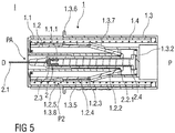
- Figure 1 shows a sectional view of an injection device I comprising a safety device 1 and a pre-filled syringe 2 retained therein as it would be presented to a user performing an injection.
- the safety device 1 comprises a substantially cylindrical and hollow needle shield 1.2, a substantially cylindrical and hollow support body 1.2 and a substantially cylindrical and hollow outer body 1.3 with a closed distal end.
- the needle shield 1.1, the support body 1.2 and the outer body 1.3 fit into each other and are arranged so as to telescope with respect to each other during an injection, so that an injection needle 2.1 of the pre-filled syringe may be exposed and inserted into the skin of a patient receiving an injection and covered after the injection delivering a dose of a medicament has been completed.
- the pre-filled syringe 2 is retained within the safety device 1 in a retracted position PR, wherein the injection needle 2.1 is covered by the needle shield 1.1.
- the pre-filled syringe 2 is releasably mounted to the outer body 1.3, so that the pre-filled syringe 2 may be translated in a distal direction D by manually translating the outer body 1.3 with respect to the needle shield 1.1 in the distal direction D.
- Two elongated latch arms 1.3.1 are formed to an inner surface of the outer body 1.3 that latch to barrel collar 2.2.1 of a syringe barrel 2.2 containing the dose of the medicament.
- the two latch arms 1.3.1 are arranged opposite to each other and are made from a resilient plastics material as to allow for a splaying of the latch arms 1.3.1 to release the pre-filled syringe 2 from being affixed to the outer body 1.3.
- the stopper 2.3 may be translated in the distal direction D by depressing the plunger 2.4 into to syringe barrel 2.2, whereby the dose of the medicament is expelled through the injection needle 2.1.
- the plunger 2.4 is firmly attached to the support body 1.2 by first clips 1.2.1 that latch to a proximal end of the plunger 2.4.
- An end wall 1.3.2 of the outer body 1.3 is arranged to bear against the support body 1.2 to push the support body 1.2 and the plunger 2.4 connected thereto in the distal direction D, so that the stopper 2.3 is translated distally to expel the dose of the medicament.
- a translation of the needle shield 1.1 relative to the outer body 1.3 is prevented by a second clip 1.3.3 formed to the distal end of the outer body 1.3.
- the second clip 1.3.3 initially latches to a proximal end of the needle shield 1.1 and may be released by manually pushing a release element 1.3.4 formed to a lateral side wall of the outer body 1.3 radially inwards, whereby the second clip 1.3.3 is deflected radial outwards to disengage from the proximal end of the needle shield 1.1.
- a compression spring 1.4 is arranged within the safety device 1 that biases the needle shield 1.1 and the outer body 1.3 away from each other. Initially, the compression spring 1.4 is in a non-energized or only slightly energized state. The compression spring 1.4 is compressed and energized during the injection when the outer body 1.3 is translated with respect to the needle shield 1.1 in the distal direction D. The energized compression spring 1.4 is capable of retracting the pre-filled syringe 2 to cover the injection needle 2.1 after the dose of the medicament has been expelled.
- the outer body 1.3 comprises a first inner sleeve 1.3.5 that is dimensioned to slide over the substantially tubular support body 1.2 when the outer body 1.3 is manually pushed in the distal direction D to insert the injection needle 2.1 and to expel the dose of the medicament through the injection needle 2.1.
- the needle shield 1.1 comprises a second inner sleeve 1.1.1 that has an inner diameter corresponding to an outer diameter of the syringe barrel 2.2.
- the pre-filled syringe 2 is inserted into the second inner sleeve 1.1.1 and is slidably arranged thereto.
- the pre-filled syringe 2 is arranged to be translated from the retracted position PR shown in figure 1 in the distal direction D to expose the injection needle 2.1.
- a shoulder 1.1.2 is formed to the second inner sleeve 1.1.1 that is arranged to abut against the barrel collar 2.2.1 to limit the distal displacement of the pre-filled syringe 2 with respect to the needle shield 1.1.
- a needle cap 2.5 is frictionally affixed to a distal end of the pre-filled syringe 2.2 to cover the injection needle 2.1.
- the needle cap 2.5 is substantially retained within the second inner sleeve 1.1.1 of the needle shield 1.1.
- a tubular cap removal tool 2.6 is arranged to clamp to a distal end of the needle cap 2.2.
- the removal tool 2.6 protrudes from the needle shield 1.1 in the distal direction and may easily be gripped and pulled by a user of the injection device I to facilitate the removal of the needle cap 2.2 before the injection is carried out.
- the removal tool 2.6 may be integral with the needle cap 2.5 or the needle cap 2.5 may have axial dimensions and may be arranged with respect to the needle shield 1.1, so that the needle cap 2.2 partially protrudes distally from the needle shield 1.1 and may be gripped and removed by the user.
- Figure 2 shows the injection device I before use in an isometric view.
- a circumferential flange 1.3.5 is formed to an outer surface of the outer body 1.3 that protrudes from the outer body 1.3 in the radial outward direction.
- the flange 1.3.5 is designed to support a hand of the user of the injection device I when a proximal section of the outer body 1.3 is gripped by the user to push the outer body 1.3 in the distal direction D in order to insert the injection needle 2.1 into the skin of the patient and dispose the dose of the medicament.
- Figures 3A and 3B show the injection device I after removal of the needle cap 2.6 and before the injection is performed.
- the sectional plane shown in figure 3A extends perpendicularly to the one shown in figure 3B .
- the first inner sleeve 1.3.5 comprises a bevelled section 1.3.7 that is arranged to abut against a pivoting arm 1.2.2 arranged with the support body 1.2 as one piece.
- the pivoting arm 1.2.2 is connected to the support body 1.2 by a section of reduced wall thickness that forms a so-called living hinge 1.2.3.
- Two pivoting arms 1.2.2 are arranged opposite to each other.
- the pivoting arms 1.2.2 may pivot about the living hinge 1.2.3 to constrict radially inwards and latch to the barrel collar 2.2.1 to permanently lock the pre-filled syringe 2 to the support body 1.2 after the dose of the medicament has been expelled.
- a third clip 1.3.8 is formed to the first inner sleeve 1.3.5 of the outer body 1.3 near its distal end.
- the third clip 1.3.8 protrudes into a correspondingly shaped first notch 1.2.4 formed to an outer surface of the support body 1.2 to retain the support body 1.2 with respect to the outer body 1.1 in a first position P1.
- the support body 1.2 In the first position P1, the support body 1.2 is spaced away from the end wall 1.3.2 of the outer body 1.3.
- the first notch 1.2.4 comprises a ramped surface that allows the support body 1.2 to be moved with respect to the outer body in a proximal direction P.
- a second notch 1.2.5 is formed to the outer surface of the support body 1.2 that is arranged to be engaged by the third clip 1.3.8 to retain the support body 1.2 in a second position P2, wherein the support body 1.2 is substantially received within the outer body 1.3 and abuts against the end wall 1.3.2 in the proximal direction P.
- the injection is carried out as follows: after removal of the needle cap 2.5, the injection device I is arranged in a manner, so that the distal end of the needle shield 1.1 rests on the skin of the patient.
- the proximal end of the outer body 1.3 is gripped by the user and the release element 1.3.4 that is designed as a push button is pressed radially inwards to release the second clip 1.3.3, so that the outer body 1.3 may be pushed in the distal direction D towards the skin of the patient.
- the support body 1.2 Upon translation of the outer body 1.3 in the distal direction D, the support body 1.2 first slides into the first inner sleeve 1.3.5 of the outer body 1.3, whereby the pivoting arm 1.2.2 engages the bevelled section 1.3.7 to deflect the pivoting arm 1.2.2 radial inwards. At the same time, the needle shield 1.1 slides into the outer body 1.3 and the compression spring 1.4 is gradually compressed and energized.
- the outer body 1.3 is pushed further in the distal direction D until the proximal end wall 1.3.2 abuts on the support body 1.2 arranged in the second position P2.
- a further distal translation of the outer body 1.3 thus translates the support body 1.2 and the pre-filled syringe 2 connected thereto in the distal direction D to insert the injection needle 2.1 into the skin of the patient.
- the needle shield 1.1 slides further into the outer body 1.3 until the pre-filled syringe 2 reaches - relative to the needle shield 1.1 - an advanced position PA shown in figure 4 .
- Figure 4 shows a sectional view of the injection device I with the pre-filled syringe 2 arranged in the advanced position PA.
- the injection needle 2.1 protrudes from the distal end of the needle shield 1.1 and penetrates the skin of the patient receiving the injection.
- the pivoting arm 1.2.2 abuts on the bevelled section 1.3.7 and is deflected in the radial inward direction.
- the barrel collar 2.2.1 abuts against the shoulder 1.1.2 formed to the second inner sleeve 1.1.1 of the needle shield 1.1 to limit the distal displacement of the pre-filled syringe 2 with respect to the needle shield 1.1.
- a further movement of the outer body 1.3 in the distal direction D deflects the latch arms 1.3.1, whereby the latch arms 1.3.1 disengage form the barrel collar 2.2.1. Furthermore, the engagement of the barrel collar 2.2.1 with the shoulder 1.1.2 limits a penetration depth of the injection needle 2.1 into the skin of the patient.
- the penetration depth may be adjusted to a subcutaneous, an intramuscular or an intradermal injection of the dose of the medicament contained in the pre-filled syringe 2.
- the support body 1.2 is substantially received within the outer body 1.3.
- the third clips 1.3.8 latch into the second notches 1.2.5 to lock the outer body 1.3 and the support body 1.2 together and hence prevent a translation of the outer body 1.3 relative to the support body 1.2 in the distal direction D.
- the outer body 1.3 is pushed further in the distal direction D towards the skin of the patient.
- the support body 1.2 and the plunger 2.4 connected thereto are translated in the distal direction D, whereby the plunger 2.4 depresses into the syringe barrel 2.2 and pushes the stopper 2.3 distally to inject the dose of the medicament.
- the stopper 2.3 bottoms out and reaches a distal end of the syringe barrel 2.2 as shown in figure 5 .
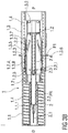
- Figure 5 shows a sectional view of the injection device I at the end of the injection stroke.
- the dose of the medicament has been completely expelled.
- the needle shield 1.1 is substantially received within the hollow outer body 1.3.
- the pivoting arms 1.2.2 constrict radially inwards and engage the barrel collar 2.2.1.
- the pre-filled syringe 2 is now locked to the support body 1.2 which is affixed to the outer body 1.3 by the third clips 1.3.8 engaging the second notch 1.2.4.
- the outer body 1.3 and the pre-filled syringe 2 connected thereto is driven in the proximal direction P towards a safe position PS by the energized compression spring 1.4.
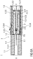
- Figure 6A and 6B show sectional views of the injection device I after the injection is completed.
- the pre-filled syringe 2 is retracted within the safety device 1 in a safe position PS.
- the needle shield 1.1 covers the injection needle 2.1 to prevent accidental needle stick injuries.
- the second clip 1.3.3 latches to the needle shield 1.1 to lock the needle shield 1.1 with respect to the pre-filled syringe 2 in the safe position PS after the injection is completed, so that a subsequent re- exposure of the injection needle 2.1 is prevented.
- a subsequent actuation of the release element 1.3.4 may release the second clip 1.3.3 to allow for a proximal movement of the needle shield 1.1 with respect to the pre-filled syringe 2 re-exposing the injection needle 2.1.
Claims (11)
- Sicherheitsvorrichtung (1) für eine vorgefüllte Spritze (2), aufweisend- einen Nadelschutz (1.1), der dazu ausgeführt ist, eine Injektionsnadel (2.1) der vorgefüllten Spritze (2) vor und nach einer Injektion abzudecken,- einen Stützkörper (1.2) mit zumindest einem Schwenkarm (1.2.2), der dazu ausgeführt ist, mit einem Zylinderbund (2.2.1) der vorgefüllten Spritze (2) in Eingriff zu gelangen, und- einen äußeren Körper (1.3) mit einer ersten inneren Hülse (1.3.5), die einen abgeschrägten Abschnitt (1.3.7) aufweist, wobei der äußere Körper (1.3) so angeordnet ist, dass er lösbar an der vorgefüllten Spritze (2) montiert ist, so dass die vorgefüllte Spritze (2) in einer distalen Richtung (D) translatiert werden kann, indem der äußere Körper (1.3) bezüglich des Nadelschutzes (1.1) in der distalen Richtung (D) manuell translatiert wird,- eine Druckfeder (1.4), die in der Sicherheitsvorrichtung (1) angeordnet ist und den Nadelschutz (1.1) und den äußeren Körper (1.3) voneinander weg vorspannt,wobei der Nadelschutz (1.1), der Stützkörper (1.2) und der äußere Körper (1.3) so angeordnet sind, dass sie bezüglich einander teleskopieren, so dass der Stützkörper (1.2) im Wesentlichen in dem äußeren Körper (1.3) aufgenommen werden kann und der Nadelschutz (1.1) im Wesentlichen in dem hohlen äußeren Körper (1.3) aufgenommen werden kann, und wobei der abgeschrägte Abschnitt (1.3.7) so angeordnet ist, dass er an dem Schwenkarm (1.2.2) anliegt, der über ein Filmscharnier (1.2.3) mit dem Stützkörper (1.2) verbunden ist, um den Schwenkarm (1.2.2) radial nach innen auszulenken und den Schwenkarm (1.2.2) an dem Zylinderbund (2.2.1) zu verrasten, um die vorgefüllte Spritze (2) nach dem Ausstoß der Dosis des Medikaments permanent an dem Stützkörper (1.2) zu verriegeln, wobei ein oder mehrere dritte Clips (1.3.8) an dem äußeren Körper (1.3) dazu angeordnet sind, in eine oder mehrere zweite Kerben (1.2.5) in dem Stützkörper (1.2) einzurasten, um den äußeren Körper (1.3) und den Stützkörper (1.2) miteinander zu verriegeln und somit eine Translation des äußeren Körpers (1.3) relativ zu dem Stützkörper (1.2) in der distalen Richtung (D) zu verhindern, so dass der äußere Körper (1.3) und die damit verbundene vorgefüllte Spritze (2) bei Entfernung der Injektionsvorrichtung (I) von einer Injektionsstelle in der proximalen Richtung (P) zu einer sicheren Position (PS) hin angetrieben werden, wobei die vorgefüllte Spritze (2) durch die gespannte Druckfeder (1.4) in die Sicherheitsvorrichtung (1) zurückgezogen wird.
- Sicherheitsvorrichtung (1) nach Anspruch 1,
dadurch gekennzeichnet, dass der Stützkörper (1.2) einen ersten Clip (1.2.1) aufweist, der dazu ausgeführt ist, einen Kolben (2.4) der vorgefüllten Spritze (2) an dem Stützkörper (1.2) anzubringen. - Sicherheitsvorrichtung (1) nach Anspruch 1 oder 2,
dadurch gekennzeichnet, dass ein zweiter Clip (1.3.3) des äußeren Körpers (1.3) in den Nadelschutz (1.1) einrastet, um eine Translation des äußeren Körpers (1.3) relativ zu dem Nadelschutz (1.1) zu verhindern, und wobei der äußere Körper (1.3) ein Löseelement (1.3.4) aufweist, das dazu angeordnet ist, manuell betätigt zu werden, um einen zweiten Clip (1.3.3) radial nach außen auszulenken, um eine Translation des äußeren Körpers (1.3) relativ zu dem Nadelschutz (1.1) zu gestatten. - Sicherheitsvorrichtung (1) nach einem der vorhergehenden Ansprüche,
dadurch gekennzeichnet, dass der Stützkörper (1.2) eine erste Kerbe (1.2.4) und die zweite Kerbe (1.2.5) aufweist und der äußere Körper (1.3) den dritten Clip (1.3.8) aufweist, der so angeordnet ist, dass er in die erste Kerbe (1.2.4) vorragt, um den Stützkörper (1.2) bezüglich des äußeren Körpers (1.3) in einer ersten Position (P1) zu halten, und wobei der dritte Clip (1.3.8) so angeordnet ist, dass er in die zweite Kerbe (1.2.5) vorragt, um den Stützkörper (1.2) bezüglich des äußeren Körpers (1.3) in einer zweiten Position (P2) zu halten, wobei der Stützkörper (1.2) in der ersten Position (P1) von einer Endwand (1.3.2) des äußeren Körpers (1.3) beabstandet ist und wobei der Stützkörper (1.2) in der zweiten Position (P2) an der Endwand (1.3.2) in einer proximalen Richtung (P) anliegt. - Sicherheitsvorrichtung (1) nach einem der vorhergehenden Ansprüche,
dadurch gekennzeichnet, dass die erste innere Hülse (1.3.5) des äußeren Körpers (1.3) so angeordnet ist, dass sie in einer radialen Richtung an dem Stützkörper (1.2) anliegt. - Injektionsvorrichtung (I), aufweisend eine Sicherheitsvorrichtung (1) nach einem der vorhergehenden Ansprüche und eine vorgefüllte Spritze (2) mit einer Injektionsnadel (2.1).
- Injektionsvorrichtung (I) nach Anspruch 6,
dadurch gekennzeichnet, dass die vorgefüllte Spritze (2) einen Kolben (2.4) aufweist, der über einen ersten Clip (1.2.1) fest an dem Stützkörper (1.2) angebracht ist, um eine gemeinsame Translation der vorgefüllten Spritze (2) und des Stützkörpers (1.2) bezüglich des Nadelschutzes (1.1) aus einer zurückgezogenen Position (PR) in eine vorgeschobene Position (PA) zu gestatten, wobei die Injektionsnadel (2.1) in der zurückgezogenen Position (PR) von dem Nadelschutz (1.1) abgedeckt ist und wobei die Injektionsnadel (2.1) in der vorgeschobenen Position (PA) in der distalen Richtung (D) von dem Nadelschutz (1.1) vorragt. - Injektionsvorrichtung (I) nach Anspruch 6 oder 7,
dadurch gekennzeichnet, dass eine nicht gespannte oder nur leicht gespannte Druckfeder (1.4) den Nadelschutz (1.1) und den äußeren Körper (1.3) voneinander weg vorspannt. - Injektionsvorrichtung (I) nach einem der Ansprüche 6 bis 8,
dadurch gekennzeichnet, dass der nach innen ausgelenkte Schwenkarm (1.2.2) dazu angeordnet ist, einen Zylinderkragen (2.2.1) in Eingriff zu nehmen, um die vorgefüllte Spritze (2) an dem Stützkörper (1.2) zu verriegeln. - Injektionsvorrichtung (I) nach Anspruch 9,
dadurch gekennzeichnet, dass die Druckfeder (1.4) in der Lage ist, die an dem Stützkörper (1.2) verriegelte vorgefüllte Spritze (2) aus der vorgeschobenen Position (PA) in eine sichere Position (PS) anzutreiben, wobei ein dritter Clip (1.3.8) des äußeren Körpers (1.3) in eine zweite Kerbe (1.2.5) vorragt, um den äußeren Körper (1.3) an dem Stützkörper (1.2) zu verriegeln. - Injektionsvorrichtung (I) nach einem der Ansprüche 5 bis 10,
dadurch gekennzeichnet, dass der Nadelschutz (1.1) eine zweite innere Hülse (1.1.1) aufweist, die einen inneren Durchmesser aufweist, der einem äußeren Durchmesser des Spritzenzylinders (2.2) entspricht.
Priority Applications (1)
| Application Number | Priority Date | Filing Date | Title |
|---|---|---|---|
| EP11808876.4A EP2661298B1 (de) | 2011-01-04 | 2011-12-30 | Sicherheitsvorrichtung und injektionsvorrichtung |
Applications Claiming Priority (3)
| Application Number | Priority Date | Filing Date | Title |
|---|---|---|---|
| EP11150081 | 2011-01-04 | ||
| EP11808876.4A EP2661298B1 (de) | 2011-01-04 | 2011-12-30 | Sicherheitsvorrichtung und injektionsvorrichtung |
| PCT/EP2011/074278 WO2012093073A1 (en) | 2011-01-04 | 2011-12-30 | Safety device and injection device |
Publications (2)
| Publication Number | Publication Date |
|---|---|
| EP2661298A1 EP2661298A1 (de) | 2013-11-13 |
| EP2661298B1 true EP2661298B1 (de) | 2019-10-02 |
Family
ID=44453828
Family Applications (1)
| Application Number | Title | Priority Date | Filing Date |
|---|---|---|---|
| EP11808876.4A Not-in-force EP2661298B1 (de) | 2011-01-04 | 2011-12-30 | Sicherheitsvorrichtung und injektionsvorrichtung |
Country Status (6)
| Country | Link |
|---|---|
| US (1) | US9248244B2 (de) |
| EP (1) | EP2661298B1 (de) |
| JP (1) | JP6134649B2 (de) |
| CA (1) | CA2824561A1 (de) |
| DK (1) | DK2661298T3 (de) |
| WO (1) | WO2012093073A1 (de) |
Families Citing this family (7)
| Publication number | Priority date | Publication date | Assignee | Title |
|---|---|---|---|---|
| EP2572741A1 (de) | 2011-09-23 | 2013-03-27 | Sanofi-Aventis Deutschland GmbH | Medikamentenabgabevorrichtung und Auslösemechanismus für eine Medikamentenabgabevorrichtung |
| IN2014CN03380A (de) | 2011-11-07 | 2015-10-09 | Safety Syringes Inc | |
| US11173254B2 (en) | 2020-03-27 | 2021-11-16 | Medivena Sp. Z O.O. | Needle-based device with a safety mechanism implemented therein |
| US20230355889A1 (en) | 2020-03-27 | 2023-11-09 | Jaroslaw Moleda | Needle-based device based on direct wing-based coupling of a needle shield to a barrel thereof and safety mechanism implemented therein |
| US11224699B2 (en) | 2020-03-27 | 2022-01-18 | Medivena Sp. Z O.O. | Needle-based device with a safety mechanism implemented therein |
| CN111658896B (zh) * | 2020-06-18 | 2020-12-15 | 普昂(杭州)医疗科技有限公司 | 一种自动触发式针头保护装置及胰岛素笔针 |
| GB2604584B (en) * | 2021-02-28 | 2023-08-02 | Owen Mumford Ltd | Injector apparatus facilitating automatic needle withdrawal |
Family Cites Families (8)
| Publication number | Priority date | Publication date | Assignee | Title |
|---|---|---|---|---|
| FR2799975B1 (fr) * | 1999-10-26 | 2003-01-10 | Plastic Omnium Cie | Dispositif de securite a tete telecospique pour seringue |
| DE10203597A1 (de) | 2002-01-30 | 2003-08-07 | Disetronic Licensing Ag | Injektionsgerät |
| US6872194B2 (en) * | 2002-01-31 | 2005-03-29 | Safety Syringes, Inc. | Disposable self-shielding syringe guard |
| US7294119B2 (en) * | 2004-06-10 | 2007-11-13 | Safety Syringes, Inc. | Passive delivery system diluents mixing and delivery |
| WO2006111862A1 (en) | 2005-04-20 | 2006-10-26 | Becton Dickinson France | Injection set and injection assistance device |
| JP2009511177A (ja) | 2005-10-11 | 2009-03-19 | イーライ リリー アンド カンパニー | 医薬品注射用の器具 |
| US20080228147A1 (en) * | 2007-03-15 | 2008-09-18 | Bristol-Myers Squibb Company | Injector for use with pre-filled syringes and method of assembly |
| UA103228C2 (uk) | 2009-03-13 | 2013-09-25 | Елі Ліллі Енд Компані | Пристрій для введення лікарських засобів з автоматичним відведенням шприца після ін'єкції |
-
2011
- 2011-12-30 CA CA2824561A patent/CA2824561A1/en not_active Abandoned
- 2011-12-30 US US13/977,943 patent/US9248244B2/en not_active Expired - Fee Related
- 2011-12-30 JP JP2013546720A patent/JP6134649B2/ja not_active Expired - Fee Related
- 2011-12-30 DK DK11808876.4T patent/DK2661298T3/da active
- 2011-12-30 EP EP11808876.4A patent/EP2661298B1/de not_active Not-in-force
- 2011-12-30 WO PCT/EP2011/074278 patent/WO2012093073A1/en active Application Filing
Non-Patent Citations (1)
| Title |
|---|
| None * |
Also Published As
| Publication number | Publication date |
|---|---|
| CA2824561A1 (en) | 2012-07-12 |
| JP6134649B2 (ja) | 2017-05-24 |
| US9248244B2 (en) | 2016-02-02 |
| JP2014503303A (ja) | 2014-02-13 |
| US20130289481A1 (en) | 2013-10-31 |
| DK2661298T3 (da) | 2019-12-16 |
| EP2661298A1 (de) | 2013-11-13 |
| WO2012093073A1 (en) | 2012-07-12 |
Similar Documents
| Publication | Publication Date | Title |
|---|---|---|
| US20220126024A1 (en) | Safety devce for a pre-filled syringe and an injection device | |
| EP2661299B1 (de) | Sicherheitsvorrichtung für eine vorgefüllte spritze und injektionsvorrichtung | |
| EP3062849B1 (de) | Medikamentenabgabevorrichtung | |
| US10471220B2 (en) | Safety device for a pre-filled syringe and an injection device | |
| DK3142730T3 (en) | MEDICINAL DISPENSER DEVICE WITH AN ACTIVATION MECHANISM | |
| EP3099356B1 (de) | Medikamentenabgabevorrichtung | |
| EP2768553B1 (de) | Autoinjektor | |
| EP2661293B1 (de) | Sicherheitsvorrichtung für eine vorgefüllte spritze und injektionsvorrichtung | |
| EP2661298B1 (de) | Sicherheitsvorrichtung und injektionsvorrichtung |
Legal Events
| Date | Code | Title | Description |
|---|---|---|---|
| PUAI | Public reference made under article 153(3) epc to a published international application that has entered the european phase |
Free format text: ORIGINAL CODE: 0009012 |
|
| 17P | Request for examination filed |
Effective date: 20130805 |
|
| AK | Designated contracting states |
Kind code of ref document: A1 Designated state(s): AL AT BE BG CH CY CZ DE DK EE ES FI FR GB GR HR HU IE IS IT LI LT LU LV MC MK MT NL NO PL PT RO RS SE SI SK SM TR |
|
| DAX | Request for extension of the european patent (deleted) | ||
| STAA | Information on the status of an ep patent application or granted ep patent |
Free format text: STATUS: EXAMINATION IS IN PROGRESS |
|
| 17Q | First examination report despatched |
Effective date: 20181211 |
|
| GRAP | Despatch of communication of intention to grant a patent |
Free format text: ORIGINAL CODE: EPIDOSNIGR1 |
|
| STAA | Information on the status of an ep patent application or granted ep patent |
Free format text: STATUS: GRANT OF PATENT IS INTENDED |
|
| RIC1 | Information provided on ipc code assigned before grant |
Ipc: A61M 5/32 20060101AFI20190402BHEP Ipc: A61M 5/28 20060101ALI20190402BHEP |
|
| INTG | Intention to grant announced |
Effective date: 20190425 |
|
| GRAS | Grant fee paid |
Free format text: ORIGINAL CODE: EPIDOSNIGR3 |
|
| GRAA | (expected) grant |
Free format text: ORIGINAL CODE: 0009210 |
|
| STAA | Information on the status of an ep patent application or granted ep patent |
Free format text: STATUS: THE PATENT HAS BEEN GRANTED |
|
| AK | Designated contracting states |
Kind code of ref document: B1 Designated state(s): AL AT BE BG CH CY CZ DE DK EE ES FI FR GB GR HR HU IE IS IT LI LT LU LV MC MK MT NL NO PL PT RO RS SE SI SK SM TR |
|
| REG | Reference to a national code |
Ref country code: GB Ref legal event code: FG4D |
|
| REG | Reference to a national code |
Ref country code: CH Ref legal event code: EP Ref country code: AT Ref legal event code: REF Ref document number: 1185508 Country of ref document: AT Kind code of ref document: T Effective date: 20191015 |
|
| REG | Reference to a national code |
Ref country code: DE Ref legal event code: R096 Ref document number: 602011062490 Country of ref document: DE |
|
| REG | Reference to a national code |
Ref country code: IE Ref legal event code: FG4D |
|
| REG | Reference to a national code |
Ref country code: DK Ref legal event code: T3 Effective date: 20191212 |
|
| REG | Reference to a national code |
Ref country code: SE Ref legal event code: TRGR |
|
| PGFP | Annual fee paid to national office [announced via postgrant information from national office to epo] |
Ref country code: SE Payment date: 20191210 Year of fee payment: 9 Ref country code: DE Payment date: 20191217 Year of fee payment: 9 |
|
| REG | Reference to a national code |
Ref country code: NL Ref legal event code: MP Effective date: 20191002 |
|
| REG | Reference to a national code |
Ref country code: LT Ref legal event code: MG4D |
|
| PGFP | Annual fee paid to national office [announced via postgrant information from national office to epo] |
Ref country code: FR Payment date: 20191216 Year of fee payment: 9 Ref country code: DK Payment date: 20191210 Year of fee payment: 9 |
|
| PGFP | Annual fee paid to national office [announced via postgrant information from national office to epo] |
Ref country code: CH Payment date: 20191213 Year of fee payment: 9 |
|
| REG | Reference to a national code |
Ref country code: AT Ref legal event code: MK05 Ref document number: 1185508 Country of ref document: AT Kind code of ref document: T Effective date: 20191002 |
|
| PG25 | Lapsed in a contracting state [announced via postgrant information from national office to epo] |
Ref country code: ES Free format text: LAPSE BECAUSE OF FAILURE TO SUBMIT A TRANSLATION OF THE DESCRIPTION OR TO PAY THE FEE WITHIN THE PRESCRIBED TIME-LIMIT Effective date: 20191002 Ref country code: AT Free format text: LAPSE BECAUSE OF FAILURE TO SUBMIT A TRANSLATION OF THE DESCRIPTION OR TO PAY THE FEE WITHIN THE PRESCRIBED TIME-LIMIT Effective date: 20191002 Ref country code: LV Free format text: LAPSE BECAUSE OF FAILURE TO SUBMIT A TRANSLATION OF THE DESCRIPTION OR TO PAY THE FEE WITHIN THE PRESCRIBED TIME-LIMIT Effective date: 20191002 Ref country code: FI Free format text: LAPSE BECAUSE OF FAILURE TO SUBMIT A TRANSLATION OF THE DESCRIPTION OR TO PAY THE FEE WITHIN THE PRESCRIBED TIME-LIMIT Effective date: 20191002 Ref country code: BG Free format text: LAPSE BECAUSE OF FAILURE TO SUBMIT A TRANSLATION OF THE DESCRIPTION OR TO PAY THE FEE WITHIN THE PRESCRIBED TIME-LIMIT Effective date: 20200102 Ref country code: PT Free format text: LAPSE BECAUSE OF FAILURE TO SUBMIT A TRANSLATION OF THE DESCRIPTION OR TO PAY THE FEE WITHIN THE PRESCRIBED TIME-LIMIT Effective date: 20200203 Ref country code: GR Free format text: LAPSE BECAUSE OF FAILURE TO SUBMIT A TRANSLATION OF THE DESCRIPTION OR TO PAY THE FEE WITHIN THE PRESCRIBED TIME-LIMIT Effective date: 20200103 Ref country code: NO Free format text: LAPSE BECAUSE OF FAILURE TO SUBMIT A TRANSLATION OF THE DESCRIPTION OR TO PAY THE FEE WITHIN THE PRESCRIBED TIME-LIMIT Effective date: 20200102 Ref country code: PL Free format text: LAPSE BECAUSE OF FAILURE TO SUBMIT A TRANSLATION OF THE DESCRIPTION OR TO PAY THE FEE WITHIN THE PRESCRIBED TIME-LIMIT Effective date: 20191002 Ref country code: LT Free format text: LAPSE BECAUSE OF FAILURE TO SUBMIT A TRANSLATION OF THE DESCRIPTION OR TO PAY THE FEE WITHIN THE PRESCRIBED TIME-LIMIT Effective date: 20191002 Ref country code: NL Free format text: LAPSE BECAUSE OF FAILURE TO SUBMIT A TRANSLATION OF THE DESCRIPTION OR TO PAY THE FEE WITHIN THE PRESCRIBED TIME-LIMIT Effective date: 20191002 |
|
| PGFP | Annual fee paid to national office [announced via postgrant information from national office to epo] |
Ref country code: GB Payment date: 20191223 Year of fee payment: 9 |
|
| PG25 | Lapsed in a contracting state [announced via postgrant information from national office to epo] |
Ref country code: HR Free format text: LAPSE BECAUSE OF FAILURE TO SUBMIT A TRANSLATION OF THE DESCRIPTION OR TO PAY THE FEE WITHIN THE PRESCRIBED TIME-LIMIT Effective date: 20191002 Ref country code: CZ Free format text: LAPSE BECAUSE OF FAILURE TO SUBMIT A TRANSLATION OF THE DESCRIPTION OR TO PAY THE FEE WITHIN THE PRESCRIBED TIME-LIMIT Effective date: 20191002 Ref country code: IS Free format text: LAPSE BECAUSE OF FAILURE TO SUBMIT A TRANSLATION OF THE DESCRIPTION OR TO PAY THE FEE WITHIN THE PRESCRIBED TIME-LIMIT Effective date: 20200224 Ref country code: RS Free format text: LAPSE BECAUSE OF FAILURE TO SUBMIT A TRANSLATION OF THE DESCRIPTION OR TO PAY THE FEE WITHIN THE PRESCRIBED TIME-LIMIT Effective date: 20191002 |
|
| PG25 | Lapsed in a contracting state [announced via postgrant information from national office to epo] |
Ref country code: AL Free format text: LAPSE BECAUSE OF FAILURE TO SUBMIT A TRANSLATION OF THE DESCRIPTION OR TO PAY THE FEE WITHIN THE PRESCRIBED TIME-LIMIT Effective date: 20191002 |
|
| REG | Reference to a national code |
Ref country code: DE Ref legal event code: R097 Ref document number: 602011062490 Country of ref document: DE |
|
| PG2D | Information on lapse in contracting state deleted |
Ref country code: IS |
|
| PG25 | Lapsed in a contracting state [announced via postgrant information from national office to epo] |
Ref country code: RO Free format text: LAPSE BECAUSE OF FAILURE TO SUBMIT A TRANSLATION OF THE DESCRIPTION OR TO PAY THE FEE WITHIN THE PRESCRIBED TIME-LIMIT Effective date: 20191002 Ref country code: EE Free format text: LAPSE BECAUSE OF FAILURE TO SUBMIT A TRANSLATION OF THE DESCRIPTION OR TO PAY THE FEE WITHIN THE PRESCRIBED TIME-LIMIT Effective date: 20191002 Ref country code: IS Free format text: LAPSE BECAUSE OF FAILURE TO SUBMIT A TRANSLATION OF THE DESCRIPTION OR TO PAY THE FEE WITHIN THE PRESCRIBED TIME-LIMIT Effective date: 20200202 |
|
| PLBE | No opposition filed within time limit |
Free format text: ORIGINAL CODE: 0009261 |
|
| STAA | Information on the status of an ep patent application or granted ep patent |
Free format text: STATUS: NO OPPOSITION FILED WITHIN TIME LIMIT |
|
| REG | Reference to a national code |
Ref country code: BE Ref legal event code: MM Effective date: 20191231 |
|
| PG25 | Lapsed in a contracting state [announced via postgrant information from national office to epo] |
Ref country code: IT Free format text: LAPSE BECAUSE OF FAILURE TO SUBMIT A TRANSLATION OF THE DESCRIPTION OR TO PAY THE FEE WITHIN THE PRESCRIBED TIME-LIMIT Effective date: 20191002 Ref country code: SM Free format text: LAPSE BECAUSE OF FAILURE TO SUBMIT A TRANSLATION OF THE DESCRIPTION OR TO PAY THE FEE WITHIN THE PRESCRIBED TIME-LIMIT Effective date: 20191002 Ref country code: MC Free format text: LAPSE BECAUSE OF FAILURE TO SUBMIT A TRANSLATION OF THE DESCRIPTION OR TO PAY THE FEE WITHIN THE PRESCRIBED TIME-LIMIT Effective date: 20191002 Ref country code: SK Free format text: LAPSE BECAUSE OF FAILURE TO SUBMIT A TRANSLATION OF THE DESCRIPTION OR TO PAY THE FEE WITHIN THE PRESCRIBED TIME-LIMIT Effective date: 20191002 |
|
| 26N | No opposition filed |
Effective date: 20200703 |
|
| PG25 | Lapsed in a contracting state [announced via postgrant information from national office to epo] |
Ref country code: IE Free format text: LAPSE BECAUSE OF NON-PAYMENT OF DUE FEES Effective date: 20191230 Ref country code: LU Free format text: LAPSE BECAUSE OF NON-PAYMENT OF DUE FEES Effective date: 20191230 |
|
| PG25 | Lapsed in a contracting state [announced via postgrant information from national office to epo] |
Ref country code: BE Free format text: LAPSE BECAUSE OF NON-PAYMENT OF DUE FEES Effective date: 20191231 Ref country code: SI Free format text: LAPSE BECAUSE OF FAILURE TO SUBMIT A TRANSLATION OF THE DESCRIPTION OR TO PAY THE FEE WITHIN THE PRESCRIBED TIME-LIMIT Effective date: 20191002 |
|
| PG25 | Lapsed in a contracting state [announced via postgrant information from national office to epo] |
Ref country code: CY Free format text: LAPSE BECAUSE OF FAILURE TO SUBMIT A TRANSLATION OF THE DESCRIPTION OR TO PAY THE FEE WITHIN THE PRESCRIBED TIME-LIMIT Effective date: 20191002 |
|
| REG | Reference to a national code |
Ref country code: DE Ref legal event code: R119 Ref document number: 602011062490 Country of ref document: DE |
|
| REG | Reference to a national code |
Ref country code: DK Ref legal event code: EBP Effective date: 20201231 |
|
| PG25 | Lapsed in a contracting state [announced via postgrant information from national office to epo] |
Ref country code: MT Free format text: LAPSE BECAUSE OF FAILURE TO SUBMIT A TRANSLATION OF THE DESCRIPTION OR TO PAY THE FEE WITHIN THE PRESCRIBED TIME-LIMIT Effective date: 20191002 Ref country code: HU Free format text: LAPSE BECAUSE OF FAILURE TO SUBMIT A TRANSLATION OF THE DESCRIPTION OR TO PAY THE FEE WITHIN THE PRESCRIBED TIME-LIMIT; INVALID AB INITIO Effective date: 20111230 |
|
| REG | Reference to a national code |
Ref country code: CH Ref legal event code: PL |
|
| REG | Reference to a national code |
Ref country code: SE Ref legal event code: EUG |
|
| GBPC | Gb: european patent ceased through non-payment of renewal fee |
Effective date: 20201230 |
|
| PG25 | Lapsed in a contracting state [announced via postgrant information from national office to epo] |
Ref country code: FR Free format text: LAPSE BECAUSE OF NON-PAYMENT OF DUE FEES Effective date: 20201231 |
|
| PG25 | Lapsed in a contracting state [announced via postgrant information from national office to epo] |
Ref country code: DE Free format text: LAPSE BECAUSE OF NON-PAYMENT OF DUE FEES Effective date: 20210701 Ref country code: CH Free format text: LAPSE BECAUSE OF NON-PAYMENT OF DUE FEES Effective date: 20201231 Ref country code: GB Free format text: LAPSE BECAUSE OF NON-PAYMENT OF DUE FEES Effective date: 20201230 Ref country code: SE Free format text: LAPSE BECAUSE OF NON-PAYMENT OF DUE FEES Effective date: 20201231 Ref country code: LI Free format text: LAPSE BECAUSE OF NON-PAYMENT OF DUE FEES Effective date: 20201231 |
|
| PG25 | Lapsed in a contracting state [announced via postgrant information from national office to epo] |
Ref country code: DK Free format text: LAPSE BECAUSE OF NON-PAYMENT OF DUE FEES Effective date: 20201231 |
|
| PG25 | Lapsed in a contracting state [announced via postgrant information from national office to epo] |
Ref country code: TR Free format text: LAPSE BECAUSE OF FAILURE TO SUBMIT A TRANSLATION OF THE DESCRIPTION OR TO PAY THE FEE WITHIN THE PRESCRIBED TIME-LIMIT Effective date: 20191002 |
|
| PG25 | Lapsed in a contracting state [announced via postgrant information from national office to epo] |
Ref country code: MK Free format text: LAPSE BECAUSE OF FAILURE TO SUBMIT A TRANSLATION OF THE DESCRIPTION OR TO PAY THE FEE WITHIN THE PRESCRIBED TIME-LIMIT Effective date: 20191002 |