EP2660948A2 - Multiple resonant cells for inductive charging pads - Google Patents
Multiple resonant cells for inductive charging pads Download PDFInfo
- Publication number
- EP2660948A2 EP2660948A2 EP13405054.1A EP13405054A EP2660948A2 EP 2660948 A2 EP2660948 A2 EP 2660948A2 EP 13405054 A EP13405054 A EP 13405054A EP 2660948 A2 EP2660948 A2 EP 2660948A2
- Authority
- EP
- European Patent Office
- Prior art keywords
- winding
- resonance
- cells
- series
- cell
- Prior art date
- Legal status (The legal status is an assumption and is not a legal conclusion. Google has not performed a legal analysis and makes no representation as to the accuracy of the status listed.)
- Withdrawn
Links
Images


Classifications
-
- H—ELECTRICITY
- H01—ELECTRIC ELEMENTS
- H01F—MAGNETS; INDUCTANCES; TRANSFORMERS; SELECTION OF MATERIALS FOR THEIR MAGNETIC PROPERTIES
- H01F38/00—Adaptations of transformers or inductances for specific applications or functions
- H01F38/14—Inductive couplings
-
- H—ELECTRICITY
- H02—GENERATION; CONVERSION OR DISTRIBUTION OF ELECTRIC POWER
- H02J—ELECTRIC POWER NETWORKS; CIRCUIT ARRANGEMENTS OR SYSTEMS FOR SUPPLYING OR DISTRIBUTING ELECTRIC POWER; SYSTEMS FOR STORING ELECTRIC ENERGY
- H02J50/00—Circuit arrangements or systems for wireless supply or distribution of electric power
- H02J50/10—Circuit arrangements or systems for wireless supply or distribution of electric power using inductive coupling
- H02J50/12—Circuit arrangements or systems for wireless supply or distribution of electric power using inductive coupling of the resonant type
-
- H—ELECTRICITY
- H02—GENERATION; CONVERSION OR DISTRIBUTION OF ELECTRIC POWER
- H02J—ELECTRIC POWER NETWORKS; CIRCUIT ARRANGEMENTS OR SYSTEMS FOR SUPPLYING OR DISTRIBUTING ELECTRIC POWER; SYSTEMS FOR STORING ELECTRIC ENERGY
- H02J50/00—Circuit arrangements or systems for wireless supply or distribution of electric power
- H02J50/90—Circuit arrangements or systems for wireless supply or distribution of electric power involving detection or optimisation of position, e.g. alignment
Definitions
- the ideal inductive charging pad would be one that in any place a receiver is placed; it would deliver efficient power to the receiver while being relatively inexpensive. Another desired trait would be that the mat would be able to charge multiple devices each with its own power level. The last requirement is very difficult to achieve.
- the present invention addresses the first requirement and may address the second.
- This present invention provides a different way of targeting the magnetic field where it is needed and in the process reduces stray magnetic fields and increases efficiency. It also further reduces and not increases the stray magnetic field by using the magnetic field properties to its advantage.
- All wireless inductive charging pads are based on a converter that pushes a square wave into a primary winding.
- the incoming waveform can be idealized as a current limited AC sine wave.
- This selection is accomplished passively by resonance of the capacitors to the leakage inductance of the circuit.
- the capacitors act as a passive switch that bypasses the current if no receiver is nearby.
- Figure 4 shows a mat configured with 3 cells with parallel resonance.
- the impedance of the capacitance and the inductance are the same and together will produce an equivalent impedance of an open.
- the full voltage is applied to all cell elements but each element will not draw current due to the resonance of the each element.
- the inductance of that cell increases and that element will start to draw current. This current is able to power the receiver.
- Each of the cells that is in resonance draws very little current from the source and virtually all reactive current needed by the inductor is provided by the cell capacitance.
Landscapes
- Engineering & Computer Science (AREA)
- Power Engineering (AREA)
- Computer Networks & Wireless Communication (AREA)
- Charge And Discharge Circuits For Batteries Or The Like (AREA)
- Secondary Cells (AREA)
Abstract
Description
- This application is related to and claims priority from
US Provisional application serial number 61/642,950 - 001 Inductive charging pads have grown in popularity but are still not gaining in popularity as fast as the wireless power industry would like. One of the selling points of wireless technology is that it relieves the consumer of the "transmitter" portion of a power supply in that the transmitter can be on a table in an airport lounge. This potentially would reduce the amount of weight that a consumer would carry to power his/her personal electronics. The main problem with wireless power is that it relies on the magnetic field, a very tightly coupled field that reduces drastically compared with other fields with distance. The reason that the magnetic field works at low distances is that it always appears as a dipole. The magnetic field must return back as a loop and it always favors the shortest path.
- 002 What is desired in an inductive charging pad is a way that the magnetic field can be moved to where the power device is sitting to be able to adequately charge the device. There have been several techniques recently purposed. Some techniques are complex or expensive and others flood the room with magnetic fields to able to compensate for the magnetic field near distance short comings.
- 003 The ideal inductive charging pad would be one that in any place a receiver is placed; it would deliver efficient power to the receiver while being relatively inexpensive. Another desired trait would be that the mat would be able to charge multiple devices each with its own power level. The last requirement is very difficult to achieve. The present invention addresses the first requirement and may address the second.
- 004 The first technique of moving the magnetic field to where it is needed has been done by placing multiple coils in zones in the mat. Then each coil is individually controlled by a different set of switches. The idea is that there are multiple primary sections with each set of switches controlling a different coil. This can become expensive due to the amount of multiple switches needed. In addition each coil has to be polled to detect where the receiver is at. Patent number
7,164,255 by Hui Shu-Yuen illustrates this idea. - 005 Another technique came from the research of MIT, which is similar to the work of Tesla. In this idea, a small transmitter coil is used somewhere in the mat while a resonant coil that goes around the mat resonates at the frequency of transmission. This resonant coil rings with the transmitter at predefined frequency increasing in power with each successive ring. This resonant coil is used to flood the whole mat with magnetic field. When a receiver is placed anywhere in the mat, the receiver acts as a damping device in the system. The transmitter adds power to the ringing system while the receiver takes power away. The amount of power ringing in the system is much larger than the power inject by the transmitter or received by the receiver. This method has the draw back of flooding the room with more power that would otherwise be needed. It is more susceptible to increased power loss into any conductive or magnetic objects in the room, including the housing of the receiver itself. Therefore, this method has proven to be less efficient and has a larger magnetic field that could impact health and violate electro-magnetic compliance regulations.
- 006 The accompanying drawings are described below in the context of this invention.
- 007 This present invention provides a different way of targeting the magnetic field where it is needed and in the process reduces stray magnetic fields and increases efficiency. It also further reduces and not increases the stray magnetic field by using the magnetic field properties to its advantage.
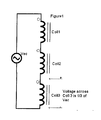
- 008 All wireless inductive charging pads are based on a converter that pushes a square wave into a primary winding. For the purpose of this disclosure the incoming waveform can be idealized as a current limited AC sine wave. Let's suppose we had multiple windings in an inductive charging pad (three of them in this illustration,
figure 1 ) configured in series. If we applied an AC voltage betweenpoint 1 and the common, all of the windings would have an equal share of the voltage thus reducing the voltage at each winding by the number of windings in series. But if we added capacitors in series with each winding as shown infigure 2 and tuned the capacitors to be the same reactive impedance as the inductors then each set of winding plus capacitors would be very close to a short. If one of the windings was in close proximity to a receiver its inductance would change and no longer be in resonance with its capacitor. In this case the inductance would increase due to the increase in mutual inductance between this winding and the receiver (figure 3 ). This "detunes" this winding and most of the applied voltage would appear across this winding. - 009 This effect would give what we desired. A voltage is applied where we need and as a consequence the magnetic field is increased in this section of the mat. If the receiver is moved to another location then another of the inductances would change and the original would return to being at a low impedance..
- 0010 This selection is accomplished passively by resonance of the capacitors to the leakage inductance of the circuit. The capacitors act as a passive switch that bypasses the current if no receiver is nearby.
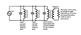
- 0011 Another configuration that can be applied using the same idea is the parallel resonance.
Figure 4 shows a mat configured with 3 cells with parallel resonance. In this case the impedance of the capacitance and the inductance are the same and together will produce an equivalent impedance of an open. The full voltage is applied to all cell elements but each element will not draw current due to the resonance of the each element. When a receiver is put in close proximity to one of the cells, the inductance of that cell increases and that element will start to draw current. This current is able to power the receiver. Each of the cells that is in resonance draws very little current from the source and virtually all reactive current needed by the inductor is provided by the cell capacitance. - 0012 It is also possible to reverse the resonances by putting the parallel resonance cells in series or by putting the series resonance cells in parallel.
- 0013 This concept is illustrated in
figure 5 for series paralleled cells. In this concept the frequency of operation is below the resonance point. When one of the cells is in close proximity to a secondary receiver its inductance increase which puts it in resonance with the operating frequency. Its impedance increase and the majority of the input voltage is applied across it. This effect is not as strong as the previous discussed effect since the cells operating in series with the resonant cell still have some impedance that will reduce the available voltage on this cell. - 0014 The converse is illustrated in
figure 6 . In this case all the series resonant cells are put in parallel. In this concept the source is again at a lower frequency than resonance. Each of the capacitors in the cells thus is a large impedance at this frequency in comparison with their inductances. Therefore, the individual inductances receive very little voltage. When a secondary is placed close to one of the cells its inductance will increase and produce a larger voltage on the primary of the transformer. In this case the cell becomes lower impedance and starts to draw more current. This extra current is applied to the load reflected from the secondary. This concept has the added benefit of reducing the magnetic field applied to regions that no secondary (receiver) exists. - 0015 In the previous concepts the actual construction of the mat has not been detailed. It is possible to layout all the windings in the same magnetic polarization. But it is beneficial to alternate the magnetic polarization between cells. This creates a coupling from cell to cell which must be compensated (will increase the starting inductance). But it produces a benefit that the magnetic field will diminish sooner with distance from the mat. This is due to creating multiple dipoles in opposite directions such that a larger distance the dipoles cancel the magnetic field. This seems counter intuitive since extending the magnetic field was the original intent. Since the magnetic field on the mat is very localized this is not needed and this added benefit will contain the magnetic field in a smaller space thus increasing efficiency overall.
Figure 7 illustrates the construction of the inductive charging pad with this concept including the parallel or series resonant capacitors.
Claims (6)
- The method of adding capacitors in a winding array for the purpose of controlling the power applied to each cell.
- The method of configuring multiple cells in series such that each cell has a series resonance capacitor and winding that resonate when no secondary winding is nearby and that a secondary winding is in close proximity to one of the cells will move it from this resonance.
- The method of configuring multiple cells in parallel such that each cell has a parallel resonant capacitor and winding that resonate when no secondary winding is nearby and if a secondary winding is in close proximity to one of the cell will move it from resonance.
- The method of putting in series multiple cells of consisting of parallel resonant capacitor and winding such that the frequency of operation is not at resonance until one of the windings is brought in close proximity to the secondary.
- The method of putting in parallel multiple cells consisting each of a series resonant capacitor and winding such that the frequency of operation is not at resonance until one of the winding is brought in close proximity to the secondary winding coil.
- The method in which multiple windings are placed in opposite polarity to one another for the purpose of canceling the magnetic field far away from the inductive charging pad.
Priority Applications (1)
| Application Number | Priority Date | Filing Date | Title |
|---|---|---|---|
| EP17179848.1A EP3264564A1 (en) | 2012-05-04 | 2013-05-06 | Multiple resonant cells for inductive charging pads |
Applications Claiming Priority (1)
| Application Number | Priority Date | Filing Date | Title |
|---|---|---|---|
| US201261642950P | 2012-05-04 | 2012-05-04 |
Related Child Applications (1)
| Application Number | Title | Priority Date | Filing Date |
|---|---|---|---|
| EP17179848.1A Division EP3264564A1 (en) | 2012-05-04 | 2013-05-06 | Multiple resonant cells for inductive charging pads |
Publications (3)
| Publication Number | Publication Date |
|---|---|
| EP2660948A2 true EP2660948A2 (en) | 2013-11-06 |
| EP2660948A3 EP2660948A3 (en) | 2015-06-24 |
| EP2660948A8 EP2660948A8 (en) | 2015-08-12 |
Family
ID=48470885
Family Applications (2)
| Application Number | Title | Priority Date | Filing Date |
|---|---|---|---|
| EP13405054.1A Withdrawn EP2660948A3 (en) | 2012-05-04 | 2013-05-06 | Multiple resonant cells for inductive charging pads |
| EP17179848.1A Ceased EP3264564A1 (en) | 2012-05-04 | 2013-05-06 | Multiple resonant cells for inductive charging pads |
Family Applications After (1)
| Application Number | Title | Priority Date | Filing Date |
|---|---|---|---|
| EP17179848.1A Ceased EP3264564A1 (en) | 2012-05-04 | 2013-05-06 | Multiple resonant cells for inductive charging pads |
Country Status (2)
| Country | Link |
|---|---|
| US (2) | US9530556B2 (en) |
| EP (2) | EP2660948A3 (en) |
Cited By (1)
| Publication number | Priority date | Publication date | Assignee | Title |
|---|---|---|---|---|
| WO2015196123A3 (en) * | 2014-06-20 | 2016-03-10 | Witricity Corporation | Wireless power transfer systems for surfaces |
Families Citing this family (19)
| Publication number | Priority date | Publication date | Assignee | Title |
|---|---|---|---|---|
| FR2980925B1 (en) * | 2011-10-03 | 2014-05-09 | Commissariat Energie Atomique | ENERGY TRANSFER SYSTEM BY ELECTROMAGNETIC COUPLING |
| JP5965741B2 (en) * | 2012-06-26 | 2016-08-10 | オリンパス株式会社 | Medical wireless power supply system |
| US10109413B2 (en) * | 2013-02-01 | 2018-10-23 | The Trustees Of Dartmouth College | Multilayer conductors with integrated capacitors and associated systems and methods |
| US20160181853A1 (en) * | 2014-12-23 | 2016-06-23 | Intel Corporation | Low emission coil topology for wireless charging |
| US11277028B2 (en) * | 2017-05-26 | 2022-03-15 | Nucurrent, Inc. | Wireless electrical energy transmission system for flexible device orientation |
| WO2019036501A1 (en) * | 2017-08-14 | 2019-02-21 | Wireless Advanced Vehicle Electrification, Inc. | Low voltage wireless power transfer pad |
| CN111742464A (en) | 2017-12-22 | 2020-10-02 | 无线先进车辆电气化有限公司 | Wireless Power Transfer Pad with Multiple Windings |
| US11462943B2 (en) | 2018-01-30 | 2022-10-04 | Wireless Advanced Vehicle Electrification, Llc | DC link charging of capacitor in a wireless power transfer pad |
| US11437854B2 (en) | 2018-02-12 | 2022-09-06 | Wireless Advanced Vehicle Electrification, Llc | Variable wireless power transfer system |
| US10950383B2 (en) * | 2018-08-24 | 2021-03-16 | Etherdyne Technologies, Inc. | Large area power transmitter for wireless power transfer |
| US11404919B2 (en) | 2020-07-24 | 2022-08-02 | Nucurrent, Inc. | Modular wireless power transmitters for powering multiple devices |
| US11476718B2 (en) | 2020-07-24 | 2022-10-18 | Nucurrent, Inc. | Systems for extending wireless power transmission charge volume utilizing repeater antennas |
| US11545857B2 (en) | 2020-07-24 | 2023-01-03 | Nucurrent, Inc. | Reconfigurable wireless power transmitter for computer peripherals |
| US11283303B2 (en) | 2020-07-24 | 2022-03-22 | Nucurrent, Inc. | Area-apportioned wireless power antenna for maximized charging volume |
| EP4186140A4 (en) * | 2020-07-24 | 2024-08-07 | NuCurrent, Inc. | SYSTEMS FOR EXPANDING A WIRELESS POWER TRANSMISSION LOAD VOLUME USING REPEATER ANTENNAS |
| TWI757968B (en) * | 2020-11-11 | 2022-03-11 | 寶德科技股份有限公司 | Mouse pad device |
| US11695302B2 (en) | 2021-02-01 | 2023-07-04 | Nucurrent, Inc. | Segmented shielding for wide area wireless power transmitter |
| US11682930B2 (en) | 2021-10-07 | 2023-06-20 | Nucurrent, Inc. | Repeater compatibility verifier for wireless power transmission system |
| KR102910367B1 (en) * | 2023-06-13 | 2026-01-09 | 주식회사 에이치엘클레무브 | Tire monitoring sensor, system and conrol method thereof, and vehicle having the same |
Family Cites Families (31)
| Publication number | Priority date | Publication date | Assignee | Title |
|---|---|---|---|---|
| US1876451A (en) | 1932-09-06 | r gurtler | ||
| FR2448722A1 (en) | 1979-02-09 | 1980-09-05 | Enertec | METHODS AND APPARATUSES FOR PERIODIC WAVEFORM ANALYSIS |
| EP0507360B1 (en) | 1991-01-30 | 1996-05-08 | The Boeing Company | Current mode bus coupler with planar coils and shields |
| KR20010032834A (en) * | 1997-12-05 | 2001-04-25 | 마크 버게스 | Supply of power to primary conductors |
| US6273022B1 (en) | 1998-03-14 | 2001-08-14 | Applied Materials, Inc. | Distributed inductively-coupled plasma source |
| DE19856937A1 (en) | 1998-12-10 | 2000-06-21 | Juergen Meins | Arrangement for the contactless inductive transmission of energy |
| US7126450B2 (en) | 1999-06-21 | 2006-10-24 | Access Business Group International Llc | Inductively powered apparatus |
| AU6788600A (en) | 1999-08-27 | 2001-03-26 | Illumagraphics, Llc | Induction electroluminescent lamp |
| JP2001076598A (en) | 1999-09-03 | 2001-03-23 | Omron Corp | Detection coil and proximity switch using this detection coil |
| WO2002065493A1 (en) | 2001-02-14 | 2002-08-22 | Fdk Corporation | Noncontact coupler |
| DE10112892B4 (en) | 2001-03-15 | 2007-12-13 | Paul Vahle Gmbh & Co. Kg | Device for transmitting data within a system for non-contact inductive energy transmission |
| GB0210886D0 (en) | 2002-05-13 | 2002-06-19 | Zap Wireless Technologies Ltd | Improvements relating to contact-less power transfer |
| EP1547222B1 (en) | 2002-06-10 | 2018-10-03 | City University of Hong Kong | Planar inductive battery charger |
| US6960968B2 (en) * | 2002-06-26 | 2005-11-01 | Koninklijke Philips Electronics N.V. | Planar resonator for wireless power transfer |
| CN1813396B (en) | 2003-05-23 | 2010-04-28 | 奥克兰联合服务有限公司 | Resonant converter and method thereof, and inductively coupled power transfer system |
| US7521890B2 (en) * | 2005-12-27 | 2009-04-21 | Power Science Inc. | System and method for selective transfer of radio frequency power |
| WO2008140333A2 (en) | 2007-05-10 | 2008-11-20 | Auckland Uniservices Limited | Multi power sourced electric vehicle |
| JP5118394B2 (en) | 2007-06-20 | 2013-01-16 | パナソニック株式会社 | Non-contact power transmission equipment |
| JP4453741B2 (en) | 2007-10-25 | 2010-04-21 | トヨタ自動車株式会社 | Electric vehicle and vehicle power supply device |
| JP5363719B2 (en) | 2007-11-12 | 2013-12-11 | リコーエレメックス株式会社 | Non-contact transmission device and core |
| US8855554B2 (en) | 2008-03-05 | 2014-10-07 | Qualcomm Incorporated | Packaging and details of a wireless power device |
| GB2458476A (en) | 2008-03-19 | 2009-09-23 | Rolls Royce Plc | Inductive electrical coupler for submerged power generation apparatus |
| US8772973B2 (en) * | 2008-09-27 | 2014-07-08 | Witricity Corporation | Integrated resonator-shield structures |
| EP2394345B1 (en) | 2009-02-05 | 2019-08-07 | Auckland UniServices Limited | Inductive power transfer apparatus |
| KR101948276B1 (en) | 2009-02-05 | 2019-02-14 | 오클랜드 유니서비시즈 리미티드 | Inductive power transfer apparatus |
| DE102009013694A1 (en) * | 2009-03-20 | 2010-09-23 | Paul Vahle Gmbh & Co. Kg | Energy transfer system with multiple primary coils |
| JP2011142177A (en) | 2010-01-06 | 2011-07-21 | Kobe Steel Ltd | Contactless power transmission device, and coil unit for contactless power transmission device |
| JP5139469B2 (en) * | 2010-04-27 | 2013-02-06 | 株式会社日本自動車部品総合研究所 | Coil unit and wireless power supply system |
| CN102906832B (en) | 2010-05-28 | 2017-06-09 | 皇家飞利浦电子股份有限公司 | For the transmitter module used in Modular electrical force transmission system |
| KR101134625B1 (en) | 2010-07-16 | 2012-04-09 | 주식회사 한림포스텍 | Core assembly for wireless power transmission, power supplying apparatus for wireless power transmission having the same, and method for manufacturing core assembly for wireless power transmission |
| WO2012018268A1 (en) | 2010-08-05 | 2012-02-09 | Auckland Uniservices Limited | Inductive power transfer apparatus |
-
2013
- 2013-05-06 EP EP13405054.1A patent/EP2660948A3/en not_active Withdrawn
- 2013-05-06 EP EP17179848.1A patent/EP3264564A1/en not_active Ceased
- 2013-05-06 US US13/887,528 patent/US9530556B2/en active Active
-
2016
- 2016-11-22 US US15/359,214 patent/US10236119B2/en active Active
Non-Patent Citations (1)
| Title |
|---|
| None |
Cited By (4)
| Publication number | Priority date | Publication date | Assignee | Title |
|---|---|---|---|---|
| WO2015196123A3 (en) * | 2014-06-20 | 2016-03-10 | Witricity Corporation | Wireless power transfer systems for surfaces |
| US9954375B2 (en) | 2014-06-20 | 2018-04-24 | Witricity Corporation | Wireless power transfer systems for surfaces |
| US10923921B2 (en) | 2014-06-20 | 2021-02-16 | Witricity Corporation | Wireless power transfer systems for surfaces |
| US11637458B2 (en) | 2014-06-20 | 2023-04-25 | Witricity Corporation | Wireless power transfer systems for surfaces |
Also Published As
| Publication number | Publication date |
|---|---|
| US20170093202A1 (en) | 2017-03-30 |
| US10236119B2 (en) | 2019-03-19 |
| US20130307347A1 (en) | 2013-11-21 |
| US9530556B2 (en) | 2016-12-27 |
| EP3264564A1 (en) | 2018-01-03 |
| EP2660948A8 (en) | 2015-08-12 |
| EP2660948A3 (en) | 2015-06-24 |
Similar Documents
| Publication | Publication Date | Title |
|---|---|---|
| US10236119B2 (en) | Multiple resonant cells wireless power mats | |
| US11251661B2 (en) | Inductive power transmitter | |
| EP3078119B1 (en) | Wireless power orthogonal polarization antenna array | |
| US10566853B2 (en) | Inductive power transmitter | |
| JP5698626B2 (en) | Wireless power receiving device, wireless power feeding device, and wireless power feeding system | |
| JP6094762B2 (en) | Wireless energy distribution system | |
| Lee et al. | A reconfigurable resonant coil for range adaptation wireless power transfer | |
| US11664683B2 (en) | Wireless charging apparatus | |
| WO2010111152A2 (en) | Magnetic inductive charging with low far fields | |
| US20180254142A1 (en) | Coil module and wireless power transmission device using the same | |
| US20200336011A1 (en) | Resonant circuit for transmitting electric energy | |
| US9030053B2 (en) | Device for collecting energy wirelessly | |
| Yoon et al. | A new circuit structure for near field wireless power transmission | |
| CN114844236A (en) | Scalable 3D wireless charging device, system and method using multiple coils | |
| Jolani et al. | A novel planar wireless power transfer system with strong coupled magnetic resonances | |
| KR101985022B1 (en) | Wireless Power Relay Apparatus and Wireless Power Transmission System | |
| KR20190101936A (en) | Wireless Power Transmitter and Receiver for Free Positioning Charging of Multiple Devices | |
| Kim et al. | Free-positioning wireless power transfer using multiple coupling coils in a transmitter | |
| US20200313461A1 (en) | Resonant circuit for transmitting electric energy without a power amplifier | |
| US9601928B2 (en) | Device for collecting energy wirelessly | |
| KR20140073083A (en) | Wireless Power Relay Apparatus and Wireless Power Transmission System | |
| WO2014069147A1 (en) | Power transmission apparatus and non-contact power transmission device | |
| JP2011060630A (en) | Self-resonant coil for induction heating device | |
| HK1232677A1 (en) | A method and an apparatus for transferring electrical power | |
| HK1232677B (en) | A method and an apparatus for transferring electrical power |
Legal Events
| Date | Code | Title | Description |
|---|---|---|---|
| PUAI | Public reference made under article 153(3) epc to a published international application that has entered the european phase |
Free format text: ORIGINAL CODE: 0009012 |
|
| AK | Designated contracting states |
Kind code of ref document: A2 Designated state(s): AL AT BE BG CH CY CZ DE DK EE ES FI FR GB GR HR HU IE IS IT LI LT LU LV MC MK MT NL NO PL PT RO RS SE SI SK SM TR |
|
| AX | Request for extension of the european patent |
Extension state: BA ME |
|
| RAP1 | Party data changed (applicant data changed or rights of an application transferred) |
Owner name: DET INTERNATIONAL HOLDING LIMITED |
|
| RIN1 | Information on inventor provided before grant (corrected) |
Inventor name: JITARU, LONEL DAN Inventor name: DAVILA, MARCO ANTONIO |
|
| RIC1 | Information provided on ipc code assigned before grant |
Ipc: H02J 7/02 20060101AFI20150205BHEP Ipc: H02J 17/00 20060101ALI20150205BHEP Ipc: H02J 5/00 20060101ALI20150205BHEP |
|
| PUAL | Search report despatched |
Free format text: ORIGINAL CODE: 0009013 |
|
| AK | Designated contracting states |
Kind code of ref document: A3 Designated state(s): AL AT BE BG CH CY CZ DE DK EE ES FI FR GB GR HR HU IE IS IT LI LT LU LV MC MK MT NL NO PL PT RO RS SE SI SK SM TR |
|
| AX | Request for extension of the european patent |
Extension state: BA ME |
|
| RIC1 | Information provided on ipc code assigned before grant |
Ipc: H02J 17/00 20060101ALI20150521BHEP Ipc: H02J 5/00 20060101ALI20150521BHEP Ipc: H02J 7/02 20060101AFI20150521BHEP |
|
| RIN1 | Information on inventor provided before grant (corrected) |
Inventor name: DAVILA, MARCO ANTONIO Inventor name: JITARU, IONEL DAN |
|
| 17P | Request for examination filed |
Effective date: 20151224 |
|
| RBV | Designated contracting states (corrected) |
Designated state(s): AL AT BE BG CH CY CZ DE DK EE ES FI FR GB GR HR HU IE IS IT LI LT LU LV MC MK MT NL NO PL PT RO RS SE SI SK SM TR |
|
| 17Q | First examination report despatched |
Effective date: 20170224 |
|
| STAA | Information on the status of an ep patent application or granted ep patent |
Free format text: STATUS: THE APPLICATION HAS BEEN WITHDRAWN |
|
| 18W | Application withdrawn |
Effective date: 20170706 |