EP2660808A2 - Transmission of alternative content over standard device connectors - Google Patents
Transmission of alternative content over standard device connectors Download PDFInfo
- Publication number
- EP2660808A2 EP2660808A2 EP13179073.5A EP13179073A EP2660808A2 EP 2660808 A2 EP2660808 A2 EP 2660808A2 EP 13179073 A EP13179073 A EP 13179073A EP 2660808 A2 EP2660808 A2 EP 2660808A2
- Authority
- EP
- European Patent Office
- Prior art keywords
- mode
- pin
- signal
- data
- standard
- Prior art date
- Legal status (The legal status is an assumption and is not a legal conclusion. Google has not performed a legal analysis and makes no representation as to the accuracy of the status listed.)
- Withdrawn
Links
Images


Classifications
-
- H—ELECTRICITY
- H04—ELECTRIC COMMUNICATION TECHNIQUE
- H04L—TRANSMISSION OF DIGITAL INFORMATION, e.g. TELEGRAPHIC COMMUNICATION
- H04L9/00—Cryptographic mechanisms or cryptographic arrangements for secret or secure communications; Network security protocols
- H04L9/40—Network security protocols
-
- G—PHYSICS
- G09—EDUCATION; CRYPTOGRAPHY; DISPLAY; ADVERTISING; SEALS
- G09G—ARRANGEMENTS OR CIRCUITS FOR CONTROL OF INDICATING DEVICES USING STATIC MEANS TO PRESENT VARIABLE INFORMATION
- G09G5/00—Control arrangements or circuits for visual indicators common to cathode-ray tube indicators and other visual indicators
- G09G5/003—Details of a display terminal, the details relating to the control arrangement of the display terminal and to the interfaces thereto
- G09G5/006—Details of the interface to the display terminal
-
- G—PHYSICS
- G06—COMPUTING; CALCULATING OR COUNTING
- G06F—ELECTRIC DIGITAL DATA PROCESSING
- G06F13/00—Interconnection of, or transfer of information or other signals between, memories, input/output devices or central processing units
- G06F13/14—Handling requests for interconnection or transfer
-
- G—PHYSICS
- G06—COMPUTING; CALCULATING OR COUNTING
- G06F—ELECTRIC DIGITAL DATA PROCESSING
- G06F13/00—Interconnection of, or transfer of information or other signals between, memories, input/output devices or central processing units
- G06F13/38—Information transfer, e.g. on bus
- G06F13/40—Bus structure
- G06F13/4063—Device-to-bus coupling
- G06F13/409—Mechanical coupling
-
- H—ELECTRICITY
- H04—ELECTRIC COMMUNICATION TECHNIQUE
- H04L—TRANSMISSION OF DIGITAL INFORMATION, e.g. TELEGRAPHIC COMMUNICATION
- H04L12/00—Data switching networks
- H04L12/28—Data switching networks characterised by path configuration, e.g. LAN [Local Area Networks] or WAN [Wide Area Networks]
- H04L12/40—Bus networks
- H04L12/40006—Architecture of a communication node
-
- G—PHYSICS
- G09—EDUCATION; CRYPTOGRAPHY; DISPLAY; ADVERTISING; SEALS
- G09G—ARRANGEMENTS OR CIRCUITS FOR CONTROL OF INDICATING DEVICES USING STATIC MEANS TO PRESENT VARIABLE INFORMATION
- G09G2370/00—Aspects of data communication
- G09G2370/10—Use of a protocol of communication by packets in interfaces along the display data pipeline
-
- G—PHYSICS
- G09—EDUCATION; CRYPTOGRAPHY; DISPLAY; ADVERTISING; SEALS
- G09G—ARRANGEMENTS OR CIRCUITS FOR CONTROL OF INDICATING DEVICES USING STATIC MEANS TO PRESENT VARIABLE INFORMATION
- G09G2370/00—Aspects of data communication
- G09G2370/12—Use of DVI or HDMI protocol in interfaces along the display data pipeline
Definitions
- Embodiments of the invention generally relate to the field of electronic devices and, more particularly, to a method and apparatus for transmission of alternative content over standard device connectors.
- HDMI TM High-Definition Multimedia Interface
- HDMI provides an interface that allows for the transfer of uncompressed digital high-definition video and audio, together with associated control signals.
- HDMI includes the High-Definition Multimedia Interface 1.3 (Hitachi, Ltd., Matsushita Electric Industrial Co., Ltd., Philips Consumer Electronics, International B.V., Silicon Image, Inc., Sony Corporation, Thomson Inc., and Toshiba Corporation) (June 22, 2006), as well as earlier and later versions of HDMI.
- HDMI is backward and forward compatible with DVI (Digital Video Interface), which contains only video data.
- HDMI is essentially a superset of DVI, containing the same video content with the addition of multi-channel audio and status data content in the gaps, or blanking periods, between bursts of video data.
- MHL TM Mobile High-Definition Link TM
- a handheld MHL device may, for example, allow for direct connection with a presentation or rendering device, including, for example, a television set, video monitor, or projector. Protocols for communication elements may include MHL technology.
- Devices used in conjunction with content storage, transmission, and presentation may include any devices capable of providing, storing, or presenting multimedia data, including television sets, video monitors, projectors, cable and satellite set-top boxes, video players, including DVD (Digital Versatile Disk) and Blu-Ray players, audio players, digital video recorders, smartphones, MIDs (Mobile Internet Devices), PIDs (Personal Internet Devices), computers including notebook computers and netbooks, and other similar devices.
- HDMI and MHL devices utilize TMDS TM (Transition Minimized Differential Signaling) technology.
- TMDS encoding converts 8 bits per TMDS data channel into a 10-bit DC-balanced, transition minimized sequence, which is then transmitted serially across the pair at a rate of 10 bits per TMDS clock period.
- An HDMI connection may include a DDC (Display Data Channel) for configuration and status exchange between a source device and a sink device, and an optional CEC (Consumer Electronics Control) protocol to provide high-level control functions among audiovisual products in a user's environment, and an MHL connection may include a control bus carrying multiplexed control signals.
- DDC Display Data Channel
- CEC Consumer Electronics Control
- Electronic devices may include various different interfaces for the transfer of data, but smaller devices may be limited with regard to connections because of physical size.
- certain handheld and other smaller devices may utilize a micro-USBTM (Universal Serial Bus), mini-USB, or standard USB connector (or socket) compatible with USB protocol, or similar connectors having limited space.
- USB connector or socket
- Figure 1 is an illustration of an embodiment of possible connections to a standard connector
- Figure 2 is an illustration of an embodiment of a connection for a receiving device having a standard connector
- Figure 3 illustrates an embodiment of mapping of high definition data for a micro-USB connector
- Figure 4 illustrates an embodiment of data mapping between HDMI, MHL, and micro-USB/MHL
- Figure 5 is an illustration of an embodiment of mapping of signals utilizing a clock signal
- Figure 6 is an illustration of an embodiment of a high definition mode and a USB mode for a connector including a separate shell;
- Figure 7 is an illustration of an embodiment of a transfer of signals between a USB connection and an HDMI connection
- Figure 8 is an illustration of an embodiment of a device having a switch to select a mode among multiple connection modes
- Figure 9 is an illustration of an embodiment of a connection for a transmitting device transmitting data to a receiving device
- Figure 10 is an illustration of an embodiment of a connection for a receiving device receiving data from a transmitting device.
- Figure 11 is a flow chart illustrating an embodiment of a system for transmission of signals.
- Embodiments of the invention are generally directed to a transmission of alternative content over standard device connectors.
- a method in a first aspect of the invention, includes connecting a first device to a second device utilizing a standard connector, the connector including multiple pins, and detecting whether the second device is operating in a standard mode or an alternative mode. If the second device is operating in the alternative mode, then switching one or more pins of the standard connector for the alternative mode and transmitting or receiving signals for the alternative mode via the plurality of pins of the standard connector.
- an apparatus in a second aspect of the invention, include an interface for a standard connector, wherein the apparatus is to utilize the interface for multiple lines, and wherein the apparatus is to detect a transmission mode of operation for a second apparatus connected to the apparatus via the interface.
- the apparatus further includes a switch to switch the interface between transmission modes, the modes including a first mode and a second mode, the switch to switch one or more connections for the lines to support the first mode and the second mode, and the apparatus to automatically switch to the second mode if the second mode is detected for the second apparatus.
- Embodiments of the invention are generally directed to transmission of alternative content over standard device connectors.
- Mobile device means any mobile electronic device.
- the term “mobile device” includes, but is not limited to, a cellular telephone, smartphone, PDA (personal digital device), MP3 or other format music player, digital camera, video recorder, digital storage device, and other similar devices.
- an apparatus, system, or method provides for transmission of alternative content over existing connectors, such as, for example, transmission of high-definition video and audio content over existing connections.
- a system or method provides for multiple modes to provide for connection for both conventional data and alternative serial data.
- a system provides for re-purposing of existing connections or pins to allow for transmission of alternative content.
- connection elements may be referred to as connectors or as sockets into which connectors may be fitted, but it is intended that the terms may be interchangeable and that either term describes a general connection element for an apparatus.
- alternative data transferred between devices may be multimedia data and associated commands, including HDMI data and commands.
- a mobile device containing high-definition video and audio data and related commands may be connected to a standard HDMI device (such as, for example, a television set, video monitor, projector, or other data presentation device).
- a standard HDMI device such as, for example, a television set, video monitor, projector, or other data presentation device.
- embodiments of the invention are not limited to any particular type of data or device.
- a device is a mobile device utilizing an MHL data connection. While embodiments of the invention are not limited to any particular technology, MHL may utilize a 5 or 6 pin interface that carries audio, video, and auxiliary data between a source and a sink.
- the MHL data may be transmitted via a standard or conventional connector by remapping the data signals to the standard connector.
- power and/or battery charging current may be provided to a mobile device (via a VBUS line) from a presentation or rendering device that is linked to the mobile device via an MHL cable.
- a standard connector may be a micro-USB (Universal Serial Bus) connector, but embodiments are not limited to any particular connector, and may also include, for example, a standard USB or mini-USB connection compatible with USB protocol or a headphone connector.
- USB Universal Serial Bus
- serialized HD high-definition
- a method may be applied to a mini-USB or standard USB connector, a headphone connector, or to another type of connection.
- serialized HD content may be digital audio and/or digital video, such as HDMI (providing video and audio data) or DVI (containing only video), Ethernet, SATA (Serial Advanced Technology Attachment), PCI (Peripheral Component Interface)-express, or high speed lane of USB 3.0.
- a micro-USB connector has 5 lines: VBUS or VCC (voltage of +5V), a differential pair D- and D+ (data + and -), ID (to distinguish between micro-USB Types A and B connectors, with pin tied to ground for Micro-A connector and not connected for Micro-B), and GND (signal ground)/Shell).
- the micro-USB connector is utilized for sending multiple lanes of alternative data, such as serialized HD contents.
- power and/or battery charging current is also received via the VBUS from a presentation or rendering device that is linked to the connector.
- a mini-USB connector also includes 5 lines, and may be similarly utilized for transmission of alternative data.
- a standard USB connector includes 4 lines, and in some embodiments the lines may be multiplexed to provide for re-purposing of the USB connector for transmission of alternative data.
- an apparatus or system may detect the type of connection, and switch to a mode for the detected type of connection, such as a selection between a high definition mode, a USB mode, and any other modes of transmission.
- a mode for the detected type of connection such as a selection between a high definition mode, a USB mode, and any other modes of transmission.
- the detection process is automatic.
- embodiments of the invention are not limited to any particular types or number of transmission modes.
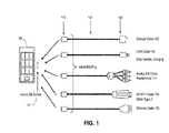
- FIG. 1 is an illustration of an embodiment of possible connections to a standard connector.
- a handheld device 105 may include a micro-USB socket 110 that is utilized for multiple purposes by switching to different transmission modes, and reassigning the pins of the socket 110 as needed to support the transmission modes.
- a device in each mode a device will utilize a cable having a first micro-USB connector 115 for connection with the micro-USB socket of the handheld device 105, but with a cable section 120 and second connector 125 that are compatible with another type of data transmission.
- the connections may include, but are not limited to, a charger cable 130 to provide power to the handheld device 105; a standard USB cable for data transfer and device charging 135; an analog A/V (audio/video) cable or headphone connection 140; a high definition digital television cable, such as HDMI type-A, for connection with an HDMI compatible device 145; or an Ethernet cable for connection to a high speed data link 150.
- the handheld device 105 may detect the type of connection when the device is connected via the micro-USB socket 110, and may automatically switch to the appropriate mode to support the connection.
- Figure 2 is an illustration of an embodiment of a connection for a receiving device having a standard connector.
- a receiving device may utilize a standard connector for multiple connections with other devices.
- a television set, video monitor, or other presentation device 205 may include one or more standard connector sockets 210, such as HDMI compatible sockets, to accept connectors 215 (such as HDMI compatible connectors) to provide multiple types of connections.
- the presentation device 205 includes a receiver that is ready to accept data via multiple protocols, including, as illustrated in Figure 2 , HDMI, MHL, SATATM (Serial ATA), Ethernet, and USB.
- the presentation device 210 may provide support for: An HDMI source device 220, such as video recorder, Blu-Ray or DVD player, set-top box, or other device via an HDMI compatible cable 225; a mobile high definition device 230, such as a smartphone or other similar device, via an MHL cable 235; a SATA compatible storage device 240 via a SATA compatible cable 245; an Ethernet network connection via an Ethernet compatible cable 255 and including an Ethernet connector 250 for link with a network; or a device including a USB connection 260, such as a computer (including a laptop or netbook computer), via a USB compatible cable 265.
- devices such as the illustrated devices may be coupled at random with any of the sockets 210.
- the presentation device 205 may, without concern to a signal format that is attached, detect a type of link that is connected with any HDMI socket, and may dynamically switch to a mode that is compatible with the link, wherein the mode switch includes remapping and re-purposing the pins of the socket to support the attached link.
- the presentation device 205 thus may utilize multiple HDMI compatible sockets to support any connection that is required for the presentation device 205, thus simplifying the physical connections required for the device.
- the presentation device 205 may then operate as a central hub for a home entertainment network that includes multiple devices utilizing varying protocols for communication.
- FIG. 3 illustrates an embodiment of mapping of high definition data for a micro-USB connector.
- a micro-USB connector or other connector may be utilized in two modes, with a first mode being a standard-mode, or specifically a USB mode in this illustration 305, and a high definition mode (or HD-mode, which may in one example be a micro-MHL mode) for alternative serial content, such as high definition MHL data 310.
- a high definition mode or HD-mode
- the USB-mode 305 maintains USB connections VBUS (which may provide power and/or battery charging current for a device), Data-, Data+, ID, and ground.
- VBUS which may provide power and/or battery charging current for a device
- FIG. 4 illustrates an embodiment of data mapping between HDMI, MHL, and micro-USB/MHL.
- an HDMI connector 405 compatible with HDMI protocol contains nineteen pins, including three differential data signals (TMDS D0+ and TMDS D0-, TMDS D1+ and TMDS D1-, and TMDS D2+ and TMDS D2-).
- An MHL connector 410 compatible with MHL protocol provides for the combination of the multiple data lanes to a single data lane TMDS (Data+ and Data-).
- a micro-USB connector 415 then provides for the two-mode operation for a USB-mode and a micro-MHL mode.
- the MHL signal which provides a single-lane HDMI with Data, Clock, and CBUS lanes, is mapped to micro-USB by limiting the CBUS to one pin and utilizing two pins to transmit one-lane of data using differential signaling.
- the micro-MHL mode may be mapped such that Signal #1 is +5V from the receiver 420 (which may be utilized to provide power and/or battery charging current for a mobile device), Signal #2 and Signal #3 are utilized for TMDS Data-, TMDS Clock+, and TMDS Data+ 425, and Signal #4 is the control bus 430.
- the VBUS (voltage or power bus) and Ground are not modified in the micro-USB interface.
- the D- and D+ lines of USB may be utilized for sending a single lane of data as differential signaling.
- the CLK may be utilized to transmit an additional lane of traffic data using common-mode signaling.
- a high-definition mode is utilized to send alternative serial data over a standard socket or connector.
- the socket or connector may be utilized to send one or more lanes of data in HD-mode.
- the HD-mode may be utilized to provide multiple differential lanes of data including use of a signal transmitted over a power line, thus using Signal #1 to transmit data in addition to the voltage provided.
- common mode signaling may be utilized to provide additional data than would be provided utilizing differential signaling alone. For example, if common-mode signaling is applied, four pins (Signals #1-#4 in this example) may be utilized to support an additional two data lanes, with the common mode signal being modulated on top of the differential signal.
- one or more lanes of HD content are sent to pins of an existing connector, such as an existing 5-pin or 6-pin micro-USB connector, while retaining the capacity to provide the original signaling, such as retaining USB signaling in a modal approach.
- the new signaling for the USB connector is supported by switching a mode, such as original USB signaling mode (USB-mode) to HD-mode.
- USB-mode original USB signaling mode
- USB-mode the electrical and logic compliance for USB is preserved, while alternative data is provided in the HD-mode.
- a modal approach includes an analog-switch, analog-multiplexer, or similar device that is utilized to select between USB signals and HD signals.
- the switching may be utilized to maintain compliance of a connection with a standard, such as maintaining USB compliance with the added new signaling.
- a standard such as maintaining USB compliance with the added new signaling.
- a 5-pin (VBUS, D-, D+, ID, GND&Shield) or 6-pin (VBUS, D-, D+, ID, GND, Shield) interface may be used to send one lane or more of serialized signals over an existing micro-USB connector.
- embodiments are not limited to two modes, and the analog switch may, for example, allow for switching to one or more modes in addition to USB-mode and HD-mode.
- a single data lane of HDMI data is provided as the main HD content.
- the data is presented as MHL data, but HD contents are not limited to MHL.
- an MHL clock lane is the same as a clock lane for HDMI, but 3 lanes of HDMI data are multiplexed to form a single lane of data, and DDC/CEC/HPD are sent over a single control bus (CBUS) signal line.
- CBUS control bus
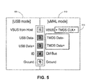
- FIG. 5 is an illustration of an embodiment of mapping of signals including a clock signal.
- a device connection may support a USB mode 505 and a micro-MHL mode 510.
- the HD data lane (Data- and Data+) is mapped to USB Data- and Data+
- the control bus is mapped to USB ID.
- the clock signal, CLK 515 may be mapped to the VBUS lane using AC coupling, as shown in Figure 5 . In this manner, the VBUS is modulated to carry additional data in addition to providing a connection for power and/or battery charging current.
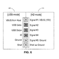
- FIG. 6 is an illustration of an embodiment of a high definition mode and a USB mode for a connector including a separate shell.
- a USB connector may provide additional signals through utilization of the separate shell.
- the utilization of the shell allows the addition of another pin for use in transmission of a signal in HD-mode. Because the shell has a larger capacitance than other connections, the shell may be better utilized as a ground signal than a signal line, but the utilization of the shell allows the ground-signal (pin #5 in Figure 6 ) to be used as another signal for HD-mode.
- a micro-USB connector may be utilized in two modes, with a first mode being a standard-mode, or specifically a USB mode in this illustration 605, and an HD-mode 610 for alternative serial content, such as high definition MHL data.
- the USB-mode 605 maintains USB connections VBUS, Data-, Data+, ID, ground, and Shell.
- Signal #1 and a VBUS voltage are mapped to VBUS, Signal #2 to Data-, Signal #3 to Data+, Signal #4 to ID, a Signal #5 / Ground to USB Ground, and the Shell to Ground.
- the use of the Shell as Ground and the Ground as Signal #5 may provide an additional pin for signal transmission.
- a system may utilize D-/D+ to provide one HD digital stream and ID/GND as provide, for example, another HD digital stream or CLK for MHL application.
- the control bus CBUS may be implemented using the common-mode of either D-/D+ or ID/GND.
- FIG. 7 is an illustration of an embodiment of a transfer of signals between a USB connection and an HDMI connection.
- the USB pins numbers 1-5 and shell 705, which are intended for USB signals VBUS, D-, D+, ID, GND, and Shield respectively 710 are re-purposed for MHL signals VBUS, TMDS-, TMDS+ and TMDS CLK+ (the clock being modulated as a common mode), CBUS, GDN, and Shield respectively 715.
- the USB pins on the mobile device are re-purposed for MHL, with the USB Data pins re-purposed for MHL TMDS data and clock and the USB ID pin re-purposed for the MHL CBUS.
- the MHL signals are applied to the pins of a USB OTG (On-The-Go) mobile device.
- the device is connected with a cable, the cable including a micro-USB connector 720, an MHL cable section 725, and an HDMI connector 730 for coupling with an HDMI socket.
- the mobile device may be utilized to provide MHL data via a micro-USB (or other) connector to an HDMI device that is compatible to receive the MHL data.
- FIG 8 is an illustration of an embodiment of a device having a switch to select a mode among multiple connection modes.
- a device 800 includes a micro-USB connector 805, which includes Pin 1, Pin 2, Pin 3, Pin 4, and Pin 5, together with a shell connection 810.
- Pin 1 may be utilized for a power connection, shown as VBUS (5V), and pin 5 and the shell connection may be tied to ground.
- Pins 2, 3, and 4 are subject to switching to support multiple modes of operation.
- the device 800 includes an analog switch 815 to switch Pins 2, 3, and 4, and thus remap these connections for the micro-USB connector 805.
- the analog switch 815 in a USB-mode the analog switch 815 is switched to connect Pin 2 to data D-, Pin 3 to data D+, and Pin 4 to ID, thereby supporting a connection with a USB subsystem 835.
- the USB-mode may be a default mode for the analog switch 815.
- the device 800 may further include an MHL transmitter 820 to transmit high definition video and audio data 830.
- the analog switch 815 is switched to connect Pin 2 to MHL data- and clock (via a common mode), Pin 3 to MHL data+, and Pin 4 to a control bus.
- the analog switch 815 may provide for switching to one or more other modes, including, for example, a connection of Pins 2, 3, and 4 to auxiliary inputs pins 825, which may be, for example, an audio input to the device 800.
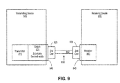
- FIG 9 is an illustration of an embodiment of a connection for a transmitting device transmitting data to a receiving device.
- the transmitting device 905, including a transmitter 915, and the receiving device 910, including a receiver 940, are connected together via a cable 930.
- the transmitting device 905 may be, for example, a handheld device, which may only have a single standard connection for data transmission, such as a micro-USB socket.
- the transmitter 915 may be, for example, an MHL transmitter, with the MHL transmitter to transmit MHL data via the single connection of the transmitting device 905.
- the transmitting device 905 further includes a switch 920 to switch between a standard-mode for transmission of standard data (such as USB data) and a second mode, which may include an HD-mode to transmit a plurality of signals related to the transfer of high definition video and audio content, such as MHL content.
- the transmitting device 905 includes a socket 940 for a standard connector, such as a micro-USB connector.
- the receiving device 910 may include a socket 945 for a connector, which may include, for example, a socket for USB connector or an MHL or HDMI connector.
- the transmitting device 905 and receiving device 910 are connected via the cable 930, the cable having a standard connector 925, such as a micro-USB connector, for connection with the transmitting device 905 and a cable section 932 and second connector 935 compatible with the communication protocol for the receiving device 910.
- the communication protocol may be USB or MHL.
- the transmitting device 905 will detect the relevant communication type when the transmitting device 905 is connected to the receiving device 910 via the cable 930, and the switch 920 will switch to the appropriate mode to map the pins of the socket 940 as required for signal transmission.
- FIG 10 is an illustration of an embodiment of a connection for a receiving device receiving data from a transmitting device.
- the receiving device 1010 including a receiver 1040, and the transmitting device 1005, including a transmitter 1015, are connected together via a cable 1030.
- the transmitting device 1005 and receiving device 1010 are at least portions of a system for the transfer of content data.
- the receiving device 1010 may be, for example, a presentation or rendering device, such as a television set or video monitor, which may include one or more communication sockets 1045, such as multiple HDMI sockets.
- the receiver 1040 may be, for example, an HDMI receiver.
- the receiving device 1010 further includes a switch 1020 to switch between a standard-mode for reception of data in a first mode (such as for HDMI data) and a second mode to receive alternative data, such as, for example, Ethernet data.
- the transmitting device 1005 may include a socket 1040 for a connector, which may include, for example, an HDMI connector or an Ethernet connector.
- the transmitting device 1005 and receiving device 1010 are connected via the cable 1030, the cable having a standard connector 1035, such as an HDMI connector, for connection with the receiving device 1010 and a cable section 1032 and second connector 1025 compatible with the communication protocol for the transmitting device 1005.
- the receiving device 1010 will detect the relevant communication type when the receiving device 1010 is connected to the transmitting device 1005 via the cable 1030, and the switch 1020 will switch to the appropriate mode to map the pins of the socket 1045 as required for signal reception.
- FIG 11 is a flow chart illustrating an embodiment of a system for transmission of signals.
- a transmitting device is connected to a receiving device 1102 via a standard connector, such as a micro-USB connector.
- the transmitting device may detect the transmission protocol for the receiving device (or the receiving device may detect the transmission protocol for the transmitting device) 1104. If, for example, the connection is a USB connection 1106, the transmitting device may remain in a USB-mode 1108 (if, for example, the default mode is the USB-mode) and transmit a standard USB data signal via the micro-USB connector 1110. If not, the transmitting device may switch to HD-mode 1112, and transmit signals via the connector 1116 (or may switch to another relevant mode 1114).
- the transmission may include, for example, the transmission of a differential high-definition signal 1118, and possible transmission of a common mode signal on the differential signal 1120.
- the transmission may further include transmission of a signal, such as a clock or control signal, over a power connection of the connector 1122.
- the transmission may further include utilizing a ground connection of the connector to transmit additional signals1124.
- Various embodiments of the present invention may include various processes. These processes may be performed by hardware components or may be embodied in computer program or machine-executable instructions, which may be used to cause a general-purpose or special-purpose processor or logic circuits programmed with the instructions to perform the processes. Alternatively, the processes may be performed by a combination of hardware and software.
- Portions of various embodiments of the present invention may be provided as a computer program product, which may include a computer-readable medium having stored thereon computer program instructions, which may be used to program a computer (or other electronic devices) to perform a process according to the embodiments of the present invention.
- the machine-readable medium may include, but is not limited to, floppy diskettes, optical disks, compact disk read-only memory (CD-ROM), and magneto-optical disks, read-only memory (ROM), random access memory (RAM), erasable programmable read-only memory (EPROM), electrically-erasable programmable read-only memory (EEPROM), magnet or optical cards, flash memory, or other type of media/machine-readable medium suitable for storing electronic instructions.
- the present invention may also be downloaded as a computer program product, wherein the program may be transferred from a remote computer to a requesting computer.
- element A may be directly coupled to element B or be indirectly coupled through, for example, element C.
- a component, feature, structure, process, or characteristic A “causes” a component, feature, structure, process, or characteristic B, it means that "A” is at least a partial cause of "B” but that there may also be at least one other component, feature, structure, process, or characteristic that assists in causing "B.”
- the specification indicates that a component, feature, structure, process, or characteristic "may”, “might”, or “could” be included, that particular component, feature, structure, process, or characteristic is not required to be included. If the specification or claim refers to "a” or “an” element, this does not mean there is only one of the described elements.
- An embodiment is an implementation or example of the present invention.
- Reference in the specification to "an embodiment,” “one embodiment,” “some embodiments,” or “other embodiments” means that a particular feature, structure, or characteristic described in connection with the embodiments is included in at least some embodiments, but not necessarily all embodiments.
- the various appearances of "an embodiment,” “one embodiment,” or “some embodiments” are not necessarily all referring to the same embodiments. It should be appreciated that in the foregoing description of exemplary embodiments of the present invention, various features are sometimes grouped together in a single embodiment, figure, or description thereof for the purpose of streamlining the disclosure and aiding in the understanding of one or more of the various inventive aspects.
Abstract
Description
- This patent application is related to and claims priority to
U.S. provisional patent application No. 61/110,326, filed October 31, 2008 - Embodiments of the invention generally relate to the field of electronic devices and, more particularly, to a method and apparatus for transmission of alternative content over standard device connectors.
- Increasingly diverse devices are utilized for data functions such as video and audio storage, transmission, and presentation or rendering. In one example, the HDMI™ (High-Definition Multimedia Interface) provides an interface that allows for the transfer of uncompressed digital high-definition video and audio, together with associated control signals. (HDMI is a trademark of HDMI Licensing, LLC) HDMI includes the High-Definition Multimedia Interface 1.3 (Hitachi, Ltd., Matsushita Electric Industrial Co., Ltd., Philips Consumer Electronics, International B.V., Silicon Image, Inc., Sony Corporation, Thomson Inc., and Toshiba Corporation) (June 22, 2006), as well as earlier and later versions of HDMI. HDMI is backward and forward compatible with DVI (Digital Video Interface), which contains only video data. HDMI is essentially a superset of DVI, containing the same video content with the addition of multi-channel audio and status data content in the gaps, or blanking periods, between bursts of video data. Further, MHL™ (Mobile High-Definition Link™) provides an audio/video interface to connect portable electronic device to other devices, allowing for transfer of HDMI information utilizing connectors with fewer pins through the multiplexing of data multiple data signals, combining three lanes of HDMI data to a single lane of multiplexed data without requiring a separate clock. A handheld MHL device may, for example, allow for direct connection with a presentation or rendering device, including, for example, a television set, video monitor, or projector. Protocols for communication elements may include MHL technology.
- Devices used in conjunction with content storage, transmission, and presentation may include any devices capable of providing, storing, or presenting multimedia data, including television sets, video monitors, projectors, cable and satellite set-top boxes, video players, including DVD (Digital Versatile Disk) and Blu-Ray players, audio players, digital video recorders, smartphones, MIDs (Mobile Internet Devices), PIDs (Personal Internet Devices), computers including notebook computers and netbooks, and other similar devices. HDMI and MHL devices utilize TMDS™ (Transition Minimized Differential Signaling) technology. TMDS encoding converts 8 bits per TMDS data channel into a 10-bit DC-balanced, transition minimized sequence, which is then transmitted serially across the pair at a rate of 10 bits per TMDS clock period. An HDMI connection may include a DDC (Display Data Channel) for configuration and status exchange between a source device and a sink device, and an optional CEC (Consumer Electronics Control) protocol to provide high-level control functions among audiovisual products in a user's environment, and an MHL connection may include a control bus carrying multiplexed control signals.
- Electronic devices may include various different interfaces for the transfer of data, but smaller devices may be limited with regard to connections because of physical size. For example, certain handheld and other smaller devices may utilize a micro-USB™ (Universal Serial Bus), mini-USB, or standard USB connector (or socket) compatible with USB protocol, or similar connectors having limited space. The limited types of connections that are available may complicate high definition data transmission.
- Embodiments of the invention are illustrated by way of example, and not by way of limitation, in the figures of the accompanying drawings in which like reference numerals refer to similar elements.
-
Figure 1 is an illustration of an embodiment of possible connections to a standard connector; -
Figure 2 is an illustration of an embodiment of a connection for a receiving device having a standard connector; -
Figure 3 illustrates an embodiment of mapping of high definition data for a micro-USB connector; -
Figure 4 illustrates an embodiment of data mapping between HDMI, MHL, and micro-USB/MHL; -
Figure 5 is an illustration of an embodiment of mapping of signals utilizing a clock signal; -
Figure 6 is an illustration of an embodiment of a high definition mode and a USB mode for a connector including a separate shell; -
Figure 7 is an illustration of an embodiment of a transfer of signals between a USB connection and an HDMI connection; -
Figure 8 is an illustration of an embodiment of a device having a switch to select a mode among multiple connection modes; -
Figure 9 is an illustration of an embodiment of a connection for a transmitting device transmitting data to a receiving device; -
Figure 10 is an illustration of an embodiment of a connection for a receiving device receiving data from a transmitting device; and -
Figure 11 is a flow chart illustrating an embodiment of a system for transmission of signals. - Embodiments of the invention are generally directed to a transmission of alternative content over standard device connectors.
- In a first aspect of the invention, a method includes connecting a first device to a second device utilizing a standard connector, the connector including multiple pins, and detecting whether the second device is operating in a standard mode or an alternative mode. If the second device is operating in the alternative mode, then switching one or more pins of the standard connector for the alternative mode and transmitting or receiving signals for the alternative mode via the plurality of pins of the standard connector.
- In a second aspect of the invention, an apparatus include an interface for a standard connector, wherein the apparatus is to utilize the interface for multiple lines, and wherein the apparatus is to detect a transmission mode of operation for a second apparatus connected to the apparatus via the interface. The apparatus further includes a switch to switch the interface between transmission modes, the modes including a first mode and a second mode, the switch to switch one or more connections for the lines to support the first mode and the second mode, and the apparatus to automatically switch to the second mode if the second mode is detected for the second apparatus.
- Embodiments of the invention are generally directed to transmission of alternative content over standard device connectors.
- As used herein:
- "Mobile device" means any mobile electronic device. The term "mobile device" includes, but is not limited to, a cellular telephone, smartphone, PDA (personal digital device), MP3 or other format music player, digital camera, video recorder, digital storage device, and other similar devices.
- In some embodiments, an apparatus, system, or method provides for transmission of alternative content over existing connectors, such as, for example, transmission of high-definition video and audio content over existing connections. In some embodiments, a system or method provides for multiple modes to provide for connection for both conventional data and alternative serial data. In some embodiments, a system provides for re-purposing of existing connections or pins to allow for transmission of alternative content. (In this description, connection elements may be referred to as connectors or as sockets into which connectors may be fitted, but it is intended that the terms may be interchangeable and that either term describes a general connection element for an apparatus.)
- In a particular embodiment, alternative data transferred between devices may be multimedia data and associated commands, including HDMI data and commands. For example, a mobile device containing high-definition video and audio data and related commands may be connected to a standard HDMI device (such as, for example, a television set, video monitor, projector, or other data presentation device). However, embodiments of the invention are not limited to any particular type of data or device.
- In some embodiments, a device is a mobile device utilizing an MHL data connection. While embodiments of the invention are not limited to any particular technology, MHL may utilize a 5 or 6 pin interface that carries audio, video, and auxiliary data between a source and a sink. In some embodiments, the MHL data may be transmitted via a standard or conventional connector by remapping the data signals to the standard connector. In some embodiments, power and/or battery charging current may be provided to a mobile device (via a VBUS line) from a presentation or rendering device that is linked to the mobile device via an MHL cable. In some embodiments, a standard connector may be a micro-USB (Universal Serial Bus) connector, but embodiments are not limited to any particular connector, and may also include, for example, a standard USB or mini-USB connection compatible with USB protocol or a headphone connector.
- In some embodiments, a system or method is provided to transmit serialized HD (high-definition) video and audio content over an existing micro-USB connector. However, in other embodiments a method may be applied to a mini-USB or standard USB connector, a headphone connector, or to another type of connection. In some embodiments serialized HD content may be digital audio and/or digital video, such as HDMI (providing video and audio data) or DVI (containing only video), Ethernet, SATA (Serial Advanced Technology Attachment), PCI (Peripheral Component Interface)-express, or high speed lane of USB 3.0.
- A micro-USB connector has 5 lines: VBUS or VCC (voltage of +5V), a differential pair D- and D+ (data + and -), ID (to distinguish between micro-USB Types A and B connectors, with pin tied to ground for Micro-A connector and not connected for Micro-B), and GND (signal ground)/Shell). In some embodiments, the micro-USB connector is utilized for sending multiple lanes of alternative data, such as serialized HD contents. In some embodiments, power and/or battery charging current is also received via the VBUS from a presentation or rendering device that is linked to the connector. A mini-USB connector also includes 5 lines, and may be similarly utilized for transmission of alternative data. A standard USB connector includes 4 lines, and in some embodiments the lines may be multiplexed to provide for re-purposing of the USB connector for transmission of alternative data.
- In some embodiments, an apparatus or system may detect the type of connection, and switch to a mode for the detected type of connection, such as a selection between a high definition mode, a USB mode, and any other modes of transmission. In some embodiments, the detection process is automatic. However, embodiments of the invention are not limited to any particular types or number of transmission modes.
-
Figure 1 is an illustration of an embodiment of possible connections to a standard connector. In this illustration, ahandheld device 105 may include amicro-USB socket 110 that is utilized for multiple purposes by switching to different transmission modes, and reassigning the pins of thesocket 110 as needed to support the transmission modes. In this illustration, in each mode a device will utilize a cable having a firstmicro-USB connector 115 for connection with the micro-USB socket of thehandheld device 105, but with acable section 120 andsecond connector 125 that are compatible with another type of data transmission. - For example, the connections may include, but are not limited to, a
charger cable 130 to provide power to thehandheld device 105; a standard USB cable for data transfer and device charging 135; an analog A/V (audio/video) cable orheadphone connection 140; a high definition digital television cable, such as HDMI type-A, for connection with an HDMIcompatible device 145; or an Ethernet cable for connection to a highspeed data link 150. In some embodiments, thehandheld device 105 may detect the type of connection when the device is connected via themicro-USB socket 110, and may automatically switch to the appropriate mode to support the connection. -
Figure 2 is an illustration of an embodiment of a connection for a receiving device having a standard connector. In some embodiments, in addition to a transmitting device utilizing a standard connector to support multiple types of connections with other devices, a receiving device may utilize a standard connector for multiple connections with other devices. - In this illustration, a television set, video monitor, or
other presentation device 205 may include one or morestandard connector sockets 210, such as HDMI compatible sockets, to accept connectors 215 (such as HDMI compatible connectors) to provide multiple types of connections. In this illustration, thepresentation device 205 includes a receiver that is ready to accept data via multiple protocols, including, as illustrated inFigure 2 , HDMI, MHL, SATA™ (Serial ATA), Ethernet, and USB. - In some implementations, the
presentation device 210 may provide support for: AnHDMI source device 220, such as video recorder, Blu-Ray or DVD player, set-top box, or other device via an HDMIcompatible cable 225; a mobilehigh definition device 230, such as a smartphone or other similar device, via anMHL cable 235; a SATAcompatible storage device 240 via a SATAcompatible cable 245; an Ethernet network connection via an Ethernetcompatible cable 255 and including anEthernet connector 250 for link with a network; or a device including aUSB connection 260, such as a computer (including a laptop or netbook computer), via a USBcompatible cable 265. In some embodiments, devices such as the illustrated devices may be coupled at random with any of thesockets 210. In some embodiments, thepresentation device 205 may, without concern to a signal format that is attached, detect a type of link that is connected with any HDMI socket, and may dynamically switch to a mode that is compatible with the link, wherein the mode switch includes remapping and re-purposing the pins of the socket to support the attached link. In some embodiments, thepresentation device 205 thus may utilize multiple HDMI compatible sockets to support any connection that is required for thepresentation device 205, thus simplifying the physical connections required for the device. In some embodiments, thepresentation device 205 may then operate as a central hub for a home entertainment network that includes multiple devices utilizing varying protocols for communication. -
Figure 3 illustrates an embodiment of mapping of high definition data for a micro-USB connector. In this illustration, a micro-USB connector or other connector may be utilized in two modes, with a first mode being a standard-mode, or specifically a USB mode in thisillustration 305, and a high definition mode (or HD-mode, which may in one example be a micro-MHL mode) for alternative serial content, such as highdefinition MHL data 310. However, embodiments of the invention are not limited to these particular modes, or to any particular number of modes. As illustrated, the USB-mode 305 maintains USB connections VBUS (which may provide power and/or battery charging current for a device), Data-, Data+, ID, and ground. For HD-mode,Signal # 1 and a VBUS voltage are mapped to VBUS,Signal # 2 to Data-,Signal # 3 to Data+,Signal # 4 to ID, and Ground to Ground. -
Figure 4 illustrates an embodiment of data mapping between HDMI, MHL, and micro-USB/MHL. As illustrated, anHDMI connector 405 compatible with HDMI protocol contains nineteen pins, including three differential data signals (TMDS D0+ and TMDS D0-, TMDS D1+ and TMDS D1-, and TMDS D2+ and TMDS D2-). AnMHL connector 410 compatible with MHL protocol provides for the combination of the multiple data lanes to a single data lane TMDS (Data+ and Data-). Amicro-USB connector 415 then provides for the two-mode operation for a USB-mode and a micro-MHL mode. The MHL signal, which provides a single-lane HDMI with Data, Clock, and CBUS lanes, is mapped to micro-USB by limiting the CBUS to one pin and utilizing two pins to transmit one-lane of data using differential signaling. In this illustration, the micro-MHL mode may be mapped such thatSignal # 1 is +5V from the receiver 420 (which may be utilized to provide power and/or battery charging current for a mobile device),Signal # 2 andSignal # 3 are utilized for TMDS Data-, TMDS Clock+, andTMDS Data+ 425, andSignal # 4 is thecontrol bus 430. In some embodiments, the VBUS (voltage or power bus) and Ground are not modified in the micro-USB interface. The D- and D+ lines of USB may be utilized for sending a single lane of data as differential signaling. In some embodiments, the CLK may be utilized to transmit an additional lane of traffic data using common-mode signaling. - In some embodiments, a high-definition mode is utilized to send alternative serial data over a standard socket or connector. In some embodiments, the socket or connector may be utilized to send one or more lanes of data in HD-mode. In some implementations, the HD-mode may be utilized to provide multiple differential lanes of data including use of a signal transmitted over a power line, thus using
Signal # 1 to transmit data in addition to the voltage provided. In some embodiments, common mode signaling may be utilized to provide additional data than would be provided utilizing differential signaling alone. For example, if common-mode signaling is applied, four pins (Signals #1-#4 in this example) may be utilized to support an additional two data lanes, with the common mode signal being modulated on top of the differential signal. - In some embodiments, one or more lanes of HD content are sent to pins of an existing connector, such as an existing 5-pin or 6-pin micro-USB connector, while retaining the capacity to provide the original signaling, such as retaining USB signaling in a modal approach. In some embodiments, the new signaling for the USB connector is supported by switching a mode, such as original USB signaling mode (USB-mode) to HD-mode. In USB-mode, the electrical and logic compliance for USB is preserved, while alternative data is provided in the HD-mode.
- In some embodiments, a modal approach includes an analog-switch, analog-multiplexer, or similar device that is utilized to select between USB signals and HD signals. In some embodiments, the switching may be utilized to maintain compliance of a connection with a standard, such as maintaining USB compliance with the added new signaling. For example, in "HD-mode", a 5-pin (VBUS, D-, D+, ID, GND&Shield) or 6-pin (VBUS, D-, D+, ID, GND, Shield) interface may be used to send one lane or more of serialized signals over an existing micro-USB connector. However, embodiments are not limited to two modes, and the analog switch may, for example, allow for switching to one or more modes in addition to USB-mode and HD-mode.
- In this specification, it is generally assumed for sake of explanation that a single data lane of HDMI data is provided as the main HD content. In some embodiments, the data is presented as MHL data, but HD contents are not limited to MHL. In an MHL implementation, an MHL clock lane is the same as a clock lane for HDMI, but 3 lanes of HDMI data are multiplexed to form a single lane of data, and DDC/CEC/HPD are sent over a single control bus (CBUS) signal line. However, complete details regarding the operation of HDMI and MHL are outside the scope of this description.
-
Figure 5 is an illustration of an embodiment of mapping of signals including a clock signal. In this particular illustration, a device connection may support aUSB mode 505 and amicro-MHL mode 510. In this implementation, the HD data lane (Data- and Data+) is mapped to USB Data- and Data+, and the control bus is mapped to USB ID. However, the clock signal,CLK 515, may be mapped to the VBUS lane using AC coupling, as shown inFigure 5 . In this manner, the VBUS is modulated to carry additional data in addition to providing a connection for power and/or battery charging current. -
Figure 6 is an illustration of an embodiment of a high definition mode and a USB mode for a connector including a separate shell. In some embodiments, a USB connector may provide additional signals through utilization of the separate shell. In some embodiments, the utilization of the shell allows the addition of another pin for use in transmission of a signal in HD-mode. Because the shell has a larger capacitance than other connections, the shell may be better utilized as a ground signal than a signal line, but the utilization of the shell allows the ground-signal (pin # 5 inFigure 6 ) to be used as another signal for HD-mode. In this illustration, a micro-USB connector may be utilized in two modes, with a first mode being a standard-mode, or specifically a USB mode in thisillustration 605, and an HD-mode 610 for alternative serial content, such as high definition MHL data. As illustrated, the USB-mode 605 maintains USB connections VBUS, Data-, Data+, ID, ground, and Shell. For HD-mode,Signal # 1 and a VBUS voltage are mapped to VBUS,Signal # 2 to Data-,Signal # 3 to Data+,Signal # 4 to ID, aSignal # 5 / Ground to USB Ground, and the Shell to Ground. - In some embodiments, the use of the Shell as Ground and the Ground as
Signal # 5 may provide an additional pin for signal transmission. In some embodiments, because of the additional pin or signal available for transmission, a system may utilize D-/D+ to provide one HD digital stream and ID/GND as provide, for example, another HD digital stream or CLK for MHL application. In an alternative embodiment, the control bus CBUS may be implemented using the common-mode of either D-/D+ or ID/GND. -
Figure 7 is an illustration of an embodiment of a transfer of signals between a USB connection and an HDMI connection. InFigure 7 , the USB pins numbers 1-5 andshell 705, which are intended for USB signals VBUS, D-, D+, ID, GND, and Shield respectively 710, are re-purposed for MHL signals VBUS, TMDS-, TMDS+ and TMDS CLK+ (the clock being modulated as a common mode), CBUS, GDN, and Shield respectively 715. Thus, the USB pins on the mobile device are re-purposed for MHL, with the USB Data pins re-purposed for MHL TMDS data and clock and the USB ID pin re-purposed for the MHL CBUS. The MHL signals are applied to the pins of a USB OTG (On-The-Go) mobile device. The device is connected with a cable, the cable including amicro-USB connector 720, anMHL cable section 725, and anHDMI connector 730 for coupling with an HDMI socket. In this manner, the mobile device may be utilized to provide MHL data via a micro-USB (or other) connector to an HDMI device that is compatible to receive the MHL data. -
Figure 8 is an illustration of an embodiment of a device having a switch to select a mode among multiple connection modes. In this illustration, adevice 800 includes amicro-USB connector 805, which includesPin 1,Pin 2,Pin 3,Pin 4, andPin 5, together with ashell connection 810. In this example,Pin 1 may be utilized for a power connection, shown as VBUS (5V), andpin 5 and the shell connection may be tied to ground.Pins device 800 includes ananalog switch 815 to switchPins micro-USB connector 805. - In this illustration, in a USB-mode the
analog switch 815 is switched to connectPin 2 to data D-,Pin 3 to data D+, andPin 4 to ID, thereby supporting a connection with aUSB subsystem 835. In some embodiments, the USB-mode may be a default mode for theanalog switch 815. Thedevice 800 may further include anMHL transmitter 820 to transmit high definition video andaudio data 830. In an MHL-mode theanalog switch 815 is switched to connectPin 2 to MHL data- and clock (via a common mode),Pin 3 to MHL data+, andPin 4 to a control bus. In some embodiments, theanalog switch 815 may provide for switching to one or more other modes, including, for example, a connection ofPins device 800. -
Figure 9 is an illustration of an embodiment of a connection for a transmitting device transmitting data to a receiving device. In this illustration, the transmittingdevice 905, including atransmitter 915, and the receivingdevice 910, including areceiver 940, are connected together via acable 930. The transmittingdevice 905 may be, for example, a handheld device, which may only have a single standard connection for data transmission, such as a micro-USB socket. Thetransmitter 915 may be, for example, an MHL transmitter, with the MHL transmitter to transmit MHL data via the single connection of the transmittingdevice 905. The transmittingdevice 905 further includes aswitch 920 to switch between a standard-mode for transmission of standard data (such as USB data) and a second mode, which may include an HD-mode to transmit a plurality of signals related to the transfer of high definition video and audio content, such as MHL content. The transmittingdevice 905 includes asocket 940 for a standard connector, such as a micro-USB connector. The receivingdevice 910 may include asocket 945 for a connector, which may include, for example, a socket for USB connector or an MHL or HDMI connector. In this illustration, the transmittingdevice 905 and receivingdevice 910 are connected via thecable 930, the cable having astandard connector 925, such as a micro-USB connector, for connection with the transmittingdevice 905 and acable section 932 andsecond connector 935 compatible with the communication protocol for the receivingdevice 910. In this illustration, the communication protocol may be USB or MHL. In some embodiments, the transmittingdevice 905 will detect the relevant communication type when the transmittingdevice 905 is connected to the receivingdevice 910 via thecable 930, and theswitch 920 will switch to the appropriate mode to map the pins of thesocket 940 as required for signal transmission. -
Figure 10 is an illustration of an embodiment of a connection for a receiving device receiving data from a transmitting device. In this illustration, thereceiving device 1010, including areceiver 1040, and thetransmitting device 1005, including atransmitter 1015, are connected together via acable 1030. In some embodiments, thetransmitting device 1005 and receivingdevice 1010 are at least portions of a system for the transfer of content data. Thereceiving device 1010 may be, for example, a presentation or rendering device, such as a television set or video monitor, which may include one ormore communication sockets 1045, such as multiple HDMI sockets. Thereceiver 1040 may be, for example, an HDMI receiver. Thereceiving device 1010 further includes aswitch 1020 to switch between a standard-mode for reception of data in a first mode (such as for HDMI data) and a second mode to receive alternative data, such as, for example, Ethernet data. Thetransmitting device 1005 may include asocket 1040 for a connector, which may include, for example, an HDMI connector or an Ethernet connector. In this illustration, thetransmitting device 1005 and receivingdevice 1010 are connected via thecable 1030, the cable having astandard connector 1035, such as an HDMI connector, for connection with thereceiving device 1010 and acable section 1032 andsecond connector 1025 compatible with the communication protocol for thetransmitting device 1005. In some embodiments, thereceiving device 1010 will detect the relevant communication type when thereceiving device 1010 is connected to thetransmitting device 1005 via thecable 1030, and theswitch 1020 will switch to the appropriate mode to map the pins of thesocket 1045 as required for signal reception. -
Figure 11 is a flow chart illustrating an embodiment of a system for transmission of signals. In this illustration, a transmitting device is connected to areceiving device 1102 via a standard connector, such as a micro-USB connector. The transmitting device may detect the transmission protocol for the receiving device (or the receiving device may detect the transmission protocol for the transmitting device) 1104. If, for example, the connection is aUSB connection 1106, the transmitting device may remain in a USB-mode 1108 (if, for example, the default mode is the USB-mode) and transmit a standard USB data signal via themicro-USB connector 1110. If not, the transmitting device may switch to HD-mode 1112, and transmit signals via the connector 1116 (or may switch to another relevant mode 1114). The transmission may include, for example, the transmission of a differential high-definition signal 1118, and possible transmission of a common mode signal on thedifferential signal 1120. The transmission may further include transmission of a signal, such as a clock or control signal, over a power connection of theconnector 1122. The transmission may further include utilizing a ground connection of the connector to transmit additional signals1124. - In the description above, for the purposes of explanation, numerous specific details are set forth in order to provide a thorough understanding of the present invention. It will be apparent, however, to one skilled in the art that the present invention may be practiced without some of these specific details. In other instances, well-known structures and devices are shown in block diagram form. There may be intermediate structure between illustrated components. The components described or illustrated herein may have additional inputs or outputs which are not illustrated or described.
- Various embodiments of the present invention may include various processes. These processes may be performed by hardware components or may be embodied in computer program or machine-executable instructions, which may be used to cause a general-purpose or special-purpose processor or logic circuits programmed with the instructions to perform the processes. Alternatively, the processes may be performed by a combination of hardware and software.
- Portions of various embodiments of the present invention may be provided as a computer program product, which may include a computer-readable medium having stored thereon computer program instructions, which may be used to program a computer (or other electronic devices) to perform a process according to the embodiments of the present invention. The machine-readable medium may include, but is not limited to, floppy diskettes, optical disks, compact disk read-only memory (CD-ROM), and magneto-optical disks, read-only memory (ROM), random access memory (RAM), erasable programmable read-only memory (EPROM), electrically-erasable programmable read-only memory (EEPROM), magnet or optical cards, flash memory, or other type of media/machine-readable medium suitable for storing electronic instructions. Moreover, the present invention may also be downloaded as a computer program product, wherein the program may be transferred from a remote computer to a requesting computer.
- Many of the methods are described in their most basic form, but processes can be added to or deleted from any of the methods and information can be added or subtracted from any of the described messages without departing from the basic scope of the present invention. It will be apparent to those skilled in the art that many further modifications and adaptations can be made. The particular embodiments are not provided to limit the invention but to illustrate it. The scope of the embodiments of the present invention is not to be determined by the specific examples provided above but only by the claims below.
- If it is said that an element "A" is coupled to or with element "B," element A may be directly coupled to element B or be indirectly coupled through, for example, element C. When the specification or claims state that a component, feature, structure, process, or characteristic A "causes" a component, feature, structure, process, or characteristic B, it means that "A" is at least a partial cause of "B" but that there may also be at least one other component, feature, structure, process, or characteristic that assists in causing "B." If the specification indicates that a component, feature, structure, process, or characteristic "may", "might", or "could" be included, that particular component, feature, structure, process, or characteristic is not required to be included. If the specification or claim refers to "a" or "an" element, this does not mean there is only one of the described elements.
- An embodiment is an implementation or example of the present invention. Reference in the specification to "an embodiment," "one embodiment," "some embodiments," or "other embodiments" means that a particular feature, structure, or characteristic described in connection with the embodiments is included in at least some embodiments, but not necessarily all embodiments. The various appearances of "an embodiment," "one embodiment," or "some embodiments" are not necessarily all referring to the same embodiments. It should be appreciated that in the foregoing description of exemplary embodiments of the present invention, various features are sometimes grouped together in a single embodiment, figure, or description thereof for the purpose of streamlining the disclosure and aiding in the understanding of one or more of the various inventive aspects. This method of disclosure, however, is not to be interpreted as reflecting an intention that the claimed invention requires more features than are expressly recited in each claim. Rather, as the following claims reflect, inventive aspects lie in less than all features of a single foregoing disclosed embodiment. Thus, the claims are hereby expressly incorporated into this description, with each claim standing on its own as a separate embodiment of this invention.
The following labeled clauses set out further aspects of the present invention: - A1. A method comprising connecting a first device to a second device utilizing a standard connector, the connector including a plurality of pins; detecting whether the second device is operating in a standard mode or an alternative mode; and upon detecting that the second device is operating in the alternative mode, switching one or more pins of the standard connector for the alternative mode and transmitting or receiving signals for the alternative mode via the plurality of pins of the standard connector.
- A2. The method of clause A1, wherein the standard connector includes a first data pin and a second data pin.
- A3. The method of clause A2, wherein the signals include a first signal, the first signal being a first differential data signal transferred using the first pin and the second pin.
- A4. The method of clause A3, wherein the signals include a common mode signal transmitted on top of the first differential data signal.
- A5. The method of clause A4, wherein the common mode signal is a clock signal.
- A6. The method of clause A4, wherein the common mode signal is a control bus signal.
- A7. The method of clause A3, wherein the standard connector further includes a third pin, the third pin being a power line, the power line to provide power, battery charging current, or both.
- A8. The method of clause A7, wherein a clock signal is transferred by modulating a power signal on the third pin.
- A9. The method of clause A3, wherein the standard connector further includes a fourth pin for identification and a fifth pin for ground, wherein a second signal is transferred via the fourth pin and the fifth pin.
- A10. The method of clause A9, wherein the second signal is a second differential data signal.
- A11. The method of clause A10, wherein the signals include a second common mode signal transmitted on the second differential signal.
- A12. The method of clause A11, wherein the second common mode signal is a clock signal.
- A13. The method of clause A1, wherein switching the pins of the standard connector includes commanding an analog switch to switch lines connected to the standard connector to support the alternative mode.
- A14. The method of clause A1, further comprising switching to a third mode and switching the pins of the standard connector for the third mode.
- A15. The method of clause A1, wherein the standard mode is a USB (universal serial bus) mode.
- A16. The method of clause A15, wherein the alternative mode is a high-definition video mode.
- A17. An apparatus comprising an interface for a standard connector, the apparatus to utilize the interface for a plurality of lines, wherein the apparatus is to detect a transmission mode of operation for a second apparatus connected to the apparatus via the interface; and a switch to switch the interface between a plurality of transmission modes, the plurality of transmission modes including a first mode and a second mode, the switch to switch one or more connections for the plurality of lines to support the first mode and the second mode, the apparatus to automatically switch to the second mode if the second mode is detected for the second apparatus.
- A18. The apparatus of clause A17, further comprising a transmitter or receiver for transfer of a plurality of signals over the lines in at least one of the transmission modes.
- A19. The apparatus of clause A17, wherein the plurality of lines includes a first line for data and a second line for data.
- A20. The apparatus of clause A19, wherein the plurality of signals includes a first signal to be transmitted over the first line and the second line, the first signal being a first differential data signal.
- A21. The apparatus of clause A19, wherein the plurality of signals includes a first common mode signal transmitted on top of the first differential data signal.
- A22. The apparatus of clause A21, wherein the first common mode signal is a clock signal.
- A23. The apparatus of clause A21, wherein the first common mode signal is a control bus signal.
- A24. The apparatus of clause A19, wherein the plurality of lines includes a third line for transmission of power, battery charging, or both, and wherein a clock signal is transmitted on the third line by modulating a power signal on the third line.
- A25. The apparatus of clause A24, wherein the plurality of lines includes a fourth line for identification and a fifth line for ground, and wherein a second signal is transferred via the fourth line and the fifth line.
- A26. The apparatus of claim 25, wherein the second signal is a second differential data signal.
- A27. The apparatus of clause A26, wherein a second common mode signal is transferred on the second differential signal.
- A28. The apparatus of clause A27, wherein the second common mode signal is a clock signal.
- A29. The apparatus of clause A17, wherein the standard connector further comprises a shell, and wherein the shell is to be utilized as a ground connection.
- A30, The apparatus of clause A17, wherein the standard connector is micro-USB (Universal Serial Bus) connector, and wherein the first mode is a USB mode.
- A31, The apparatus of clause A30, wherein the second mode is a high definition mode, and wherein the apparatus is to transmit or receive high definition video content over the plurality of lines in the second mode.
- A32. A system comprising a receiving device to receive data, the receiving device including a first socket for an interface, the interface including a plurality of lines; and a transmitting device to transfer a plurality of signals to the receiving device, the transmitting device including a second socket to connect with the receiving device via the interface; wherein the receiving device, the transmitting device, or both the receiving device and the transmitting device include a switch to switch the interface between a plurality of transmission modes, the plurality of transmission modes including a first mode and a second mode, the switch to switch one or more connections for the plurality of lines to support the first mode and the second mode, the receiving device or transmitting device to automatically switch to the second mode if the second mode is detected for the other device.
- A33. The system of clause A32, wherein the first socket or the second socket is a standard socket, and wherein the standard socket includes one or more pins that are re-purposed for transmission of data in the second mode.
- A34. The system of clause A33, wherein the standard socket includes a first pin and a second pin for data in the first mode that are re-purposed for differential data signals and a common mode signal transmitted on top of the differential data signal.
- A35. The system of clause A34, wherein the common mode signal is one of a clock signal or a control bus signal.
- A36. The system of clause A33, wherein the standard socket includes a third pin for transmission of power, battery charging, or both, and wherein the third pin is re-purposed for the transmission of a clock signal by modulating a power signal on the third pin.
- A37. The system of clause A33, wherein the standard socket includes a fourth pin for identification and a fifth pin for ground, and wherein the fourth pin and the fifth pin are re-purposed for transmission of a second differential signal applied to the fourth pin and the fifth pin.
- A38. The system of clause A33, wherein the first socket is the standard socket, the first socket being a socket compatible with USB™ (Universal Serial Bus) protocol.
- A39. The system of clause A33, wherein the second socket is the standard socket, the second socket being a socket compatible with HDMI™ (High-Definition Multimedia Interface).
- A40. The system of clause A33, further comprising a cable, the cable including a first connector compatible with the first socket and a second connector compatible with the second socket.
- A41. An apparatus comprising a means for interfacing with a second apparatus over a plurality of lines; a means for detecting a transmission mode for the second apparatus, the transmission being one of a plurality of transmission modes including a first mode and a second mode; and a means for automatically switching one or more connections for the plurality of lines to support the first mode and the second mode based on the detected transmission mode for the second apparatus.
Claims (15)
- A method for transmission of alternative content over standard connectors comprising:connecting a first device to a second device utilizing a standard connector for a standard mode, the connector including a plurality of pins for the transfer of signals between the first device and the second device, the plurality of pins including a first pin for a power line, a second pin to identify the standard connector, a first data pin, a second data pin, and a ground pin;detecting whether the second device is operating in the standard mode or an alternative mode, wherein the standard mode includes transmission of a first type of data according to a first protocol and the alternative mode includes transmission of a second type of data according to a second protocol, wherein the data for the second protocol includes a differential data signal and a control signal;upon detecting the second device is operating in the standard mode, transmitting or receiving data signals of the first type according to the first protocol via the plurality of pins of the standard connector; and upon detecting that the second device is operating in the alternative mode, switching one or more pins of the standard connector for the alternative mode and transmitting or receiving data signals of the second type according to the second protocol via the plurality of pins of the standard connector; wherein the switching of the one or more pins of the standard connector for the alternative mode includes switching one or more additional pins of the standard connector to transmit the control signal.
- The method of claim 1, wherein the switching of the one or more pins of the standard connector for the alternative mode includes switching the first pin to modulate the power line to transit a clock signal in addition to operation as a power line.
- The method of claim 1, wherein the signals for the alternative mode include a first differential data signal using the first data pin and the second data pin, the first data pin and the second data pin being a first differential pair.
- The method of claim 3, wherein the signals for the alternative mode include a common mode signal transmitted on the first differential pair, wherein the common mode signal is a clock signal.
- The method of claim 3, wherein the standard connector further includes a shell, wherein for the alternative mode the shell is used for ground and the ground pin of the connector is used for signal transmission, and a second signal is transferred via the second pin and the ground pin.
- The method of claim 5, wherein the second signal is a second differential data signal, the second pin and the ground pin being a second differential pair.
- The method of claim 6, wherein the signals include a second common mode signal transmitted on the second differential pair, wherein the second common mode signal is the control signal.
- The method of claim 1, wherein switching the pins of the standard connector includes commanding an analog switch to switch lines connected to the standard connector to support the alternative mode.
- An apparatus for transmission of alternative content over standard connectors comprising:an interface for a standard connector for a standard mode, the apparatus to utilize the interface for a plurality of lines, wherein the apparatus is to detect a transmission mode of operation for a second apparatus connected to the apparatus via the interface, wherein the connector includes a plurality of pins for the transfer of signals, the plurality of pins including a first pin for a power line, a second pin to identify the standard connector, a first data pin, a second data pin, and a ground pin; and a switch to switch the interface between a plurality of transmission modes, the plurality of transmission modes including the first standard mode and a second alternative mode, the switch to switch one or more connections for the plurality of lines to support the standard mode and the alternative mode, the apparatus to automatically switch to the alternative mode if the alternative mode is detected for the second apparatus;wherein the standard mode includes transmission of a first type of data according to a first protocol and the alternative mode includes transmission of a second type of data according to a second protocol, wherein the data for the second protocol includes a differential data signal and a control signal;wherein the switching of the one or more pins of the standard connector for the alternative mode includes switching one or more additional pins of the standard connector to transmit the control signal.
- The apparatus of claim 9, the switching of the one or more pins of the standard connector for the alternative mode includes switching the first pin to modulate the power line to transit a clock signal in addition to operation as a power line.
- The apparatus of claim 9, wherein signals for the alternative mode includes a first signal to be transmitted over the first pin and the second pin, the first signal being a differential data signal, the first pin and the second pin being a first differential pair.
- The apparatus of claim 11, wherein the signals for the alternative mode include a first common mode signal transmitted on the first differential pair, wherein the first common mode signal is a clock signal.
- The apparatus of claim 12, wherein a second common mode signal is transferred on the second differential pair, wherein the second common mode signal is the control signal.
- The apparatus of claim 9, wherein the standard connector further comprises a shell, and wherein for the alternative mode the shell is to be utilized as a ground connection and the ground pin of the connector is used for signal transmission, a second signal to be transferred via the second pin and the ground pin, wherein the second signal is a differential data signal, the second pin and the ground pin being a second differential pair.
- The apparatus of claim 9, wherein the standard connector is a micro-USB™ (Universal Serial Bus) connector, and wherein the first standard mode is a USB mode, and wherein the second alternative mode is a high definition mode, and wherein the apparatus is to transmit or receive high definition video content over the plurality of lines in the alternative mode.
Applications Claiming Priority (3)
| Application Number | Priority Date | Filing Date | Title |
|---|---|---|---|
| US11032608P | 2008-10-31 | 2008-10-31 | |
| US12/606,096 US8176214B2 (en) | 2008-10-31 | 2009-10-26 | Transmission of alternative content over standard device connectors |
| EP09749258.1A EP2351141B1 (en) | 2008-10-31 | 2009-10-27 | Transmission of alternative content over standard device connectors |
Related Parent Applications (3)
| Application Number | Title | Priority Date | Filing Date |
|---|---|---|---|
| EP09749258.1A Division EP2351141B1 (en) | 2008-10-31 | 2009-10-27 | Transmission of alternative content over standard device connectors |
| EP09749258.1A Division-Into EP2351141B1 (en) | 2008-10-31 | 2009-10-27 | Transmission of alternative content over standard device connectors |
| EP09749258.1 Division | 2009-10-27 |
Publications (2)
| Publication Number | Publication Date |
|---|---|
| EP2660808A2 true EP2660808A2 (en) | 2013-11-06 |
| EP2660808A3 EP2660808A3 (en) | 2014-09-03 |
Family
ID=42102332
Family Applications (2)
| Application Number | Title | Priority Date | Filing Date |
|---|---|---|---|
| EP09749258.1A Active EP2351141B1 (en) | 2008-10-31 | 2009-10-27 | Transmission of alternative content over standard device connectors |
| EP13179073.5A Withdrawn EP2660808A3 (en) | 2008-10-31 | 2009-10-27 | Transmission of alternative content over standard device connectors |
Family Applications Before (1)
| Application Number | Title | Priority Date | Filing Date |
|---|---|---|---|
| EP09749258.1A Active EP2351141B1 (en) | 2008-10-31 | 2009-10-27 | Transmission of alternative content over standard device connectors |
Country Status (7)
| Country | Link |
|---|---|
| US (1) | US8176214B2 (en) |
| EP (2) | EP2351141B1 (en) |
| JP (1) | JP5616897B2 (en) |
| KR (1) | KR101480735B1 (en) |
| CN (1) | CN102203851B (en) |
| TW (1) | TWI483116B (en) |
| WO (1) | WO2010051281A2 (en) |
Cited By (1)
| Publication number | Priority date | Publication date | Assignee | Title |
|---|---|---|---|---|
| EP3260988A4 (en) * | 2015-03-12 | 2018-03-14 | Huawei Technologies Co., Ltd. | Peripheral interface multiplexing method, user equipment and external device |
Families Citing this family (106)
| Publication number | Priority date | Publication date | Assignee | Title |
|---|---|---|---|---|
| US7899492B2 (en) | 2004-07-16 | 2011-03-01 | Sellerbid, Inc. | Methods, systems and apparatus for displaying the multimedia information from wireless communication networks |
| US20140071818A1 (en) | 2004-07-16 | 2014-03-13 | Virginia Innovation Sciences, Inc. | Method and system for efficient communication |
| US8976799B1 (en) | 2007-10-01 | 2015-03-10 | Apple Inc. | Converged computer I/O system and bridging mechanism for peer-to-peer communication |
| WO2009147839A1 (en) * | 2008-06-03 | 2009-12-10 | キヤノン株式会社 | Communication device and conversion adapter |
| TWI334546B (en) * | 2009-03-13 | 2010-12-11 | Via Tech Inc | Integrated circuits |
| JP2010288283A (en) * | 2009-06-15 | 2010-12-24 | Fairchild Semiconductor Corp | Universal serial bus (usb) for digital video |
| US8841886B2 (en) * | 2009-09-11 | 2014-09-23 | Nxp B.V. | Power charging of mobile devices via a HDMI interface |
| US8799537B1 (en) * | 2009-09-25 | 2014-08-05 | Analogix Semiconductor, Inc. | Transfer of uncompressed multimedia contents and data communications |
| US8806094B2 (en) | 2009-09-25 | 2014-08-12 | Analogix Semiconductor, Inc. | Transfer of uncompressed multimedia contents or data communications |
| US8472351B2 (en) * | 2009-10-28 | 2013-06-25 | Transwitch Corporation | Fast Ethernet and HDMI Ethernet channel physical layer circuit |
| US8583836B2 (en) * | 2010-02-03 | 2013-11-12 | Stmicroelectronics, Inc. | Packet-based digital display interface signal mapping to bi-directional serial interface signals |
| JP5496722B2 (en) * | 2010-03-18 | 2014-05-21 | パナソニック株式会社 | Information processing system |
| US8825860B2 (en) * | 2010-03-30 | 2014-09-02 | Qualcomm, Incorporated | Method and apparatus to facilitate voice activity detection and coexistence manager decisions |
| US8270840B2 (en) | 2010-04-06 | 2012-09-18 | Via Technologies, Inc. | Backward compatible optical USB device |
| US8234416B2 (en) * | 2010-04-06 | 2012-07-31 | Via Technologies, Inc. | Apparatus interoperable with backward compatible optical USB device |
| JP5671838B2 (en) * | 2010-05-21 | 2015-02-18 | ソニー株式会社 | Data transmitting apparatus, data receiving apparatus, data transmitting method and data receiving method |
| EP2390969A1 (en) * | 2010-05-26 | 2011-11-30 | Samsung Electronics Co., Ltd. | Connector and interface device |
| US8484387B2 (en) * | 2010-06-30 | 2013-07-09 | Silicon Image, Inc. | Detection of cable connections for electronic devices |
| CN102315576B (en) | 2010-06-30 | 2014-08-06 | 苹果公司 | Power distribution inside cable |
| US9112310B2 (en) | 2010-06-30 | 2015-08-18 | Apple Inc. | Spark gap for high-speed cable connectors |
| US8327536B2 (en) | 2010-06-30 | 2012-12-11 | Apple Inc. | Method of manufacturing high-speed connector inserts and cables |
| US8601173B2 (en) * | 2010-06-30 | 2013-12-03 | Silicon Image, Inc. | Detection of cable connections for electronic devices |
| US8930692B2 (en) * | 2010-07-23 | 2015-01-06 | Silicon Image, Inc. | Mechanism for internal processing of content through partial authentication on secondary channel |
| US9654810B2 (en) * | 2010-07-23 | 2017-05-16 | Lattice Semiconductor Corporation | Mechanism for partial encryption of data streams |
| US20120068538A1 (en) * | 2010-09-20 | 2012-03-22 | Cywee Group Limited | Electronic device having data transmission interface capable of receiving external power and transmitting electronic data |
| JP5598220B2 (en) * | 2010-09-30 | 2014-10-01 | ソニー株式会社 | Transmission device, transmission method, reception device, reception method, and transmission / reception system |
| JP5771986B2 (en) * | 2010-12-28 | 2015-09-02 | ソニー株式会社 | Electronic device, electronic device control method, and electronic device system |
| US8489784B2 (en) * | 2010-12-31 | 2013-07-16 | Silicon Image, Inc. | Adaptive interconnection scheme for multimedia devices |
| US9047073B2 (en) * | 2011-02-14 | 2015-06-02 | Nikon Corporation | System method for detecting a type of device wherein a potential level of the device determines if power should be supplied based on the type of the device |
| US8966134B2 (en) | 2011-02-23 | 2015-02-24 | Apple Inc. | Cross-over and bypass configurations for high-speed data transmission |
| KR101566174B1 (en) | 2011-03-02 | 2015-11-05 | 삼성전자 주식회사 | Image processing apparatus and control method thereof |
| JP5742406B2 (en) | 2011-04-08 | 2015-07-01 | 富士通株式会社 | Information processing apparatus, connection method, and program |
| US8683087B2 (en) * | 2011-04-11 | 2014-03-25 | Fairchild Semiconductor Corporation | Mobile device auto detection apparatus and method |
| US9395780B2 (en) | 2011-04-21 | 2016-07-19 | Texas Instruments Incorporated | USB bridge circuit gating RID—A and RID—GND for IDGND |
| KR101286358B1 (en) | 2011-08-11 | 2013-07-15 | 엘지전자 주식회사 | Display method and apparatus |
| WO2013022177A1 (en) * | 2011-08-11 | 2013-02-14 | Lg Electronics Inc. | Image display method and apparatus |
| US8838845B2 (en) * | 2011-09-23 | 2014-09-16 | Qualcomm Incorporated | Multimedia interface with content protection in a wireless communication device |
| US8494585B2 (en) | 2011-10-13 | 2013-07-23 | The Boeing Company | Portable communication devices with accessory functions and related methods |
| JP2013090060A (en) * | 2011-10-14 | 2013-05-13 | Toshiba Corp | Video processing device and video processing method |
| CN103222279B (en) * | 2011-10-20 | 2016-10-12 | 华为终端有限公司 | Earphone interface is multiplexed with Multipurpose connector and the hand-hold electronic equipments of high resolution video and audio interface |
| CN102377970B (en) * | 2011-10-27 | 2014-01-15 | 浙江一舟电子科技股份有限公司 | MHL (Mobile High-Definition Link) data conversion system |
| US9158722B1 (en) * | 2011-11-02 | 2015-10-13 | Western Digital Technologies, Inc. | Data storage device to communicate with a host in a SATA or a USB mode |
| JP5444310B2 (en) * | 2011-11-17 | 2014-03-19 | 株式会社東芝 | Bidirectional communication interface device, transmission device, and reception device |
| KR101891147B1 (en) * | 2011-12-12 | 2018-08-23 | 삼성전자주식회사 | APPARATAS AND METHOD FOR DUAL DISPLAY OF TELEVISION USING FOR High Definition Multimedia Interface IN A PORTABLE TERMINAL |
| US8775713B2 (en) * | 2011-12-27 | 2014-07-08 | Intel Corporation | Multi-protocol tunneling over an I/O interconnect |
| US8856420B2 (en) * | 2011-12-27 | 2014-10-07 | Intel Corporation | Multi-protocol I/O interconnect flow control |
| KR101187269B1 (en) * | 2012-01-16 | 2012-10-09 | 한동엘앤씨(주) | Electronic apparatus for transmitting/receiving data using mhl interface and data transmitting/receiving method thereof |
| TWI554063B (en) * | 2012-01-20 | 2016-10-11 | 瑞昱半導體股份有限公司 | Electronic device having network auto-switching functions and a network auto-switching method utilized in an electronic device |
| US8782321B2 (en) | 2012-02-08 | 2014-07-15 | Intel Corporation | PCI express tunneling over a multi-protocol I/O interconnect |
| JP2013168750A (en) | 2012-02-14 | 2013-08-29 | Funai Electric Co Ltd | Television receiver |
| US9588931B2 (en) * | 2012-02-15 | 2017-03-07 | Lattice Semiconductor Corporation | Communication bridging between devices via multiple bridge elements |
| US9537644B2 (en) | 2012-02-23 | 2017-01-03 | Lattice Semiconductor Corporation | Transmitting multiple differential signals over a reduced number of physical channels |
| JP5803896B2 (en) * | 2012-02-23 | 2015-11-04 | ソニー株式会社 | I / O device |
| US8880923B2 (en) | 2012-03-29 | 2014-11-04 | Intel Corporation | Link power management in an I/O interconnect |
| CN202615376U (en) * | 2012-04-28 | 2012-12-19 | 中兴通讯股份有限公司 | Connecting device, mobile device and display device |
| US8954628B2 (en) * | 2012-06-05 | 2015-02-10 | Htc Corporation | Portable device and peripheral extension dock |
| CN102833513B (en) * | 2012-06-29 | 2015-10-28 | 惠州市德赛视听科技有限公司 | High definition player |
| US8959272B2 (en) * | 2012-07-06 | 2015-02-17 | Blackberry Limited | Interposer and intelligent multiplexer to provide a plurality of peripherial buses |
| CN102890666B (en) | 2012-07-13 | 2015-09-30 | 华为终端有限公司 | A kind of devices and methods therefor of shared interface, communication terminal |
| CN103794190B (en) * | 2012-10-26 | 2016-08-10 | 纬创资通股份有限公司 | There is the attachment means of electro-static discharge protection function |
| EP2765571A1 (en) * | 2013-02-08 | 2014-08-13 | BlackBerry Limited | Micro USB3.0 connector for simultaneous video, power and data transmission (NGC-e) |
| US9230505B2 (en) | 2013-02-25 | 2016-01-05 | Lattice Semiconductor Corporation | Apparatus, system and method for providing clock and data signaling |
| KR102012937B1 (en) * | 2013-03-04 | 2019-08-22 | 삼성전자주식회사 | Apparatus and method for connecting an external device in a portable terminal |
| CN103237189B (en) * | 2013-03-26 | 2016-01-13 | 小米科技有限责任公司 | Electronic equipment, MHL connector, MHL system and connector detection method |
| TWI501085B (en) * | 2013-05-17 | 2015-09-21 | Primax Electronics Ltd | Usb interface detection device |
| KR102048222B1 (en) | 2013-05-21 | 2019-11-25 | 삼성전자주식회사 | Apparatus and method for recognizing an external device in a communication system |
| CN103797785A (en) * | 2013-06-28 | 2014-05-14 | 株式会社东芝 | TV set and remote controller |
| EP2821988A1 (en) * | 2013-07-02 | 2015-01-07 | Samsung Electronics Co., Ltd | Connector for reducing near-end crosstalk |
| US20150032912A1 (en) * | 2013-07-25 | 2015-01-29 | Kabushiki Kaisha Toshiba | Information processing apparatus and information processing method |
| US20150334333A1 (en) * | 2013-07-30 | 2015-11-19 | Kabushiki Kaisha Toshiba | Electronic device and method for controlling the same |
| US9041863B2 (en) * | 2013-08-30 | 2015-05-26 | Xiaomi Inc. | Electronic device and method for displaying resources |
| US9497221B2 (en) | 2013-09-12 | 2016-11-15 | The Boeing Company | Mobile communication device and method of operating thereof |
| US9819661B2 (en) | 2013-09-12 | 2017-11-14 | The Boeing Company | Method of authorizing an operation to be performed on a targeted computing device |
| US9892087B2 (en) | 2013-09-12 | 2018-02-13 | The Boeing Company | Mobile computing device and method of transmitting data therefrom |
| US10064240B2 (en) | 2013-09-12 | 2018-08-28 | The Boeing Company | Mobile communication device and method of operating thereof |
| TWI510096B (en) * | 2013-10-04 | 2015-11-21 | Realtek Semiconductor Corp | Data receiving device and method thereof |
| CN104579325B (en) * | 2013-10-10 | 2017-09-05 | 瑞昱半导体股份有限公司 | Data sink and method |
| JP2015089704A (en) * | 2013-11-05 | 2015-05-11 | 富士通株式会社 | On-vehicle device, data communication method, and data communication program |
| CN104618666B (en) | 2013-11-05 | 2018-04-10 | 南宁富桂精密工业有限公司 | audio signal control circuit |
| US9401706B2 (en) | 2014-01-27 | 2016-07-26 | Lattice Semiconductor Corporation | Apparatus, system and method for providing switching with a T-coil circuit |
| CN103997614B (en) * | 2014-03-28 | 2017-11-24 | 惠州市德赛西威汽车电子股份有限公司 | A kind of vehicle-mounted USB+AUX_IN integrated devices |
| CN105451045A (en) * | 2014-05-28 | 2016-03-30 | 纬创资通股份有限公司 | Electronic device and video data receiving method |
| US9871516B2 (en) | 2014-06-04 | 2018-01-16 | Lattice Semiconductor Corporation | Transmitting apparatus with source termination |
| KR20160001267A (en) * | 2014-06-27 | 2016-01-06 | 삼성전자주식회사 | Connector plug and connector socket |
| CN104202631A (en) * | 2014-09-12 | 2014-12-10 | 灿芯半导体(上海)有限公司 | MHL-USB (mobile high-definition link and universal serial bus) joint circuit and portable electronic device |
| US10440424B2 (en) * | 2014-10-17 | 2019-10-08 | Sony Corporation | Transmission apparatus, transmission method, reception apparatus, and reception method |
| GB2561772B (en) * | 2015-02-25 | 2019-06-05 | Cirrus Logic Int Semiconductor Ltd | Connectors for audio data transfer |
| KR102391100B1 (en) | 2015-06-10 | 2022-04-27 | 삼성전자주식회사 | Method and apparatus for providing interface |
| US20180239718A1 (en) * | 2015-10-15 | 2018-08-23 | Hewlett-Packard Devlopment Company, L.P. | Utilizing Pins on a Universal Serial Bus (USB) Type-C Connector for a Data Signal |
| US10169265B2 (en) * | 2015-10-16 | 2019-01-01 | Gopro, Inc. | Configurable input / output connector in a camera |
| TWI593292B (en) * | 2015-11-13 | 2017-07-21 | 晨星半導體股份有限公司 | Multimedia communication apparatus and control method for audio and video transmission over standard cable |
| CN109155871B (en) * | 2016-04-26 | 2020-11-13 | 麦克赛尔株式会社 | Image output system, image output device and connection cable |
| KR102575430B1 (en) | 2016-10-25 | 2023-09-06 | 삼성전자 주식회사 | Electronic device and method for recognizing connected terminals of external device thereof |
| TWI602065B (en) * | 2016-12-02 | 2017-10-11 | 宇瞻科技股份有限公司 | Compound electronic device |
| WO2019000189A1 (en) * | 2017-06-26 | 2019-01-03 | Tridonic Gmbh & Co Kg | Adaptor and controlling method for the same |
| EP3422196A1 (en) * | 2017-06-29 | 2019-01-02 | Vestel Elektronik Sanayi ve Ticaret A.S. | Port termination |
| US11146851B2 (en) * | 2017-09-25 | 2021-10-12 | Sony Corporation | Cable, method of controlling cable, connection device, electronic device, and method of controlling electronic device |
| US10582152B2 (en) | 2017-12-28 | 2020-03-03 | Texas Instruments Incorporated | Dynamic direction control in active cable |
| TWI704734B (en) * | 2018-10-12 | 2020-09-11 | 技嘉科技股份有限公司 | External electrical connector and computer system |
| TWI731295B (en) * | 2019-01-24 | 2021-06-21 | 宏碁股份有限公司 | Display apparatus and method for controlling display apparatus |
| US10971110B2 (en) * | 2019-08-26 | 2021-04-06 | Novatek Microelectronics Corp. | Circuit and method for use in a first display device to facilitate communication with a second display device, and display communication system |
| JP6792045B2 (en) * | 2019-11-01 | 2020-11-25 | マクセル株式会社 | Video output device |
| JP7396934B2 (en) * | 2020-03-06 | 2023-12-12 | マクセル株式会社 | Transmitting device, relay device, and receiving device |
| JP7286603B2 (en) * | 2020-10-16 | 2023-06-05 | Tvs Regza株式会社 | receiver |
| TWI797908B (en) * | 2021-12-23 | 2023-04-01 | 智原科技股份有限公司 | Serial signal detector and differential signal detection method covering multi-protocols |
| KR20230153846A (en) * | 2022-04-29 | 2023-11-07 | 삼성전자주식회사 | Apparatus for multi-display control |
Family Cites Families (23)
| Publication number | Priority date | Publication date | Assignee | Title |
|---|---|---|---|---|
| AU2279095A (en) * | 1994-06-03 | 1996-01-04 | Motorola, Inc. | A dual function interface for pcmcia compatible peripheral cards and method of use therein |
| JP2757832B2 (en) * | 1995-08-14 | 1998-05-25 | 日本電気株式会社 | Terminal device |
| JPH1069339A (en) * | 1996-08-28 | 1998-03-10 | Nec Yonezawa Ltd | Interface mechanism for connecting external equipment |
| JP2000148316A (en) * | 1998-11-06 | 2000-05-26 | Matsushita Electric Ind Co Ltd | Portable terminal equipment, interface switching method for the same and recording medium |
| US7836236B2 (en) * | 2004-02-12 | 2010-11-16 | Super Talent Electronics, Inc. | Extended secure-digital (SD) devices and hosts |
| JP2001109697A (en) * | 1999-10-07 | 2001-04-20 | Victor Co Of Japan Ltd | Multiinterface device and bios processing method |
| JP4659175B2 (en) * | 2000-04-25 | 2011-03-30 | 富士通東芝モバイルコミュニケーションズ株式会社 | Mobile communication terminal |
| JP2003263253A (en) * | 2002-03-07 | 2003-09-19 | Fuji Xerox Co Ltd | Usb device |
| US8068485B2 (en) * | 2003-05-01 | 2011-11-29 | Genesis Microchip Inc. | Multimedia interface |
| CN1831851A (en) * | 2004-09-07 | 2006-09-13 | 瑞程科技股份有限公司 | Interface for a removable electronic device |
| CN1838099A (en) * | 2005-03-21 | 2006-09-27 | 大智电子科技公司 | Host and apparatus with multiple communication protocol modes, apparatus with single mode and method thereof |
| US9202210B2 (en) * | 2005-11-23 | 2015-12-01 | Sandisk Il Ltd. | Digital rights management device and method |
| TWI337710B (en) * | 2006-01-05 | 2011-02-21 | Telechips Inc | Audio system |
| US7416419B2 (en) * | 2006-08-16 | 2008-08-26 | Sandisk Corporation | Methods for ESD protection |
| US7589559B2 (en) * | 2006-12-20 | 2009-09-15 | Silicon Image, Inc. | Current mode circuitry to modulate a common mode voltage |
| US7769930B2 (en) * | 2007-01-03 | 2010-08-03 | Aten International Co., Ltd. | Keyboard-video-mouse cable having indicator for indicating switching status |
| JP2009060204A (en) * | 2007-08-30 | 2009-03-19 | Panasonic Corp | Device used in common as source and sink |
| US7956618B2 (en) * | 2007-10-31 | 2011-06-07 | Sony Ericsson Mobile Communications Ab | Additional pins on a USB connector |
| US20090128189A1 (en) * | 2007-11-19 | 2009-05-21 | Raminda Udaya Madurawe | Three dimensional programmable devices |
| US7856520B2 (en) * | 2008-01-04 | 2010-12-21 | Silicon Image, Inc. | Control bus for connection of electronic devices |
| US7921231B2 (en) * | 2008-01-04 | 2011-04-05 | Silicon Image, Inc. | Discovery of electronic devices utilizing a control bus |
| US8363707B2 (en) * | 2008-03-21 | 2013-01-29 | Micron Technology, Inc. | Mixed-mode signaling |
| US7788428B2 (en) | 2008-03-27 | 2010-08-31 | Sony Ericsson Mobile Communications Ab | Multiplex mobile high-definition link (MHL) and USB 3.0 |
-
2009
- 2009-10-26 US US12/606,096 patent/US8176214B2/en active Active
- 2009-10-27 EP EP09749258.1A patent/EP2351141B1/en active Active
- 2009-10-27 KR KR1020117012397A patent/KR101480735B1/en active IP Right Grant
- 2009-10-27 CN CN200980143836.4A patent/CN102203851B/en active Active
- 2009-10-27 WO PCT/US2009/062232 patent/WO2010051281A2/en active Application Filing
- 2009-10-27 EP EP13179073.5A patent/EP2660808A3/en not_active Withdrawn
- 2009-10-27 JP JP2011534682A patent/JP5616897B2/en active Active
- 2009-10-29 TW TW098136754A patent/TWI483116B/en active
Non-Patent Citations (1)
| Title |
|---|
| None |
Cited By (2)
| Publication number | Priority date | Publication date | Assignee | Title |
|---|---|---|---|---|
| EP3260988A4 (en) * | 2015-03-12 | 2018-03-14 | Huawei Technologies Co., Ltd. | Peripheral interface multiplexing method, user equipment and external device |
| US10331580B2 (en) | 2015-03-12 | 2019-06-25 | Huawei Technologies Co., Ltd. | Peripheral interface multiplexing method, user equipment, and external device |
Also Published As
| Publication number | Publication date |
|---|---|
| KR20110091716A (en) | 2011-08-12 |
| JP2012507947A (en) | 2012-03-29 |
| US20100109795A1 (en) | 2010-05-06 |
| WO2010051281A2 (en) | 2010-05-06 |
| WO2010051281A3 (en) | 2010-06-24 |
| KR101480735B1 (en) | 2015-01-09 |
| CN102203851B (en) | 2016-10-26 |
| TWI483116B (en) | 2015-05-01 |
| TW201019126A (en) | 2010-05-16 |
| JP5616897B2 (en) | 2014-10-29 |
| EP2660808A3 (en) | 2014-09-03 |
| US8176214B2 (en) | 2012-05-08 |
| EP2351141B1 (en) | 2014-06-11 |
| CN102203851A (en) | 2011-09-28 |
| EP2351141A2 (en) | 2011-08-03 |
Similar Documents
| Publication | Publication Date | Title |
|---|---|---|
| US8176214B2 (en) | Transmission of alternative content over standard device connectors | |
| EP2917843B1 (en) | Flexible implementation of serial bus support over display interface | |
| US7937501B2 (en) | Displayport CE system control functionality | |
| EP2711843B1 (en) | DisplayPort over USB mechanical interface | |
| US9819995B2 (en) | Device and method for data transmission and reception using HDMI | |
| US20080007616A1 (en) | Universal multimedia display adapter | |
| US10216683B2 (en) | Multimedia communication apparatus and control method for multimedia data transmission over standard cable | |
| US20080084834A1 (en) | Multiplexed connection interface for multimedia serial data transmission | |
| US8370536B2 (en) | Method and apparatus for providing robust display digital channel transmission | |
| US9554179B2 (en) | Method and apparatus for transmitting and receiving data using HDMI | |
| US10511798B2 (en) | Method for transmitting and receiving power using HDMI and apparatus therefor | |
| EP2610744A1 (en) | Electronic system, control method thereof, display apparatus, upgrade apparatus, and data input/output processing method of display apparatus | |
| US8509591B2 (en) | Transmission apparatus, reception apparatus, and transmission method | |
| TW201405316A (en) | Display port data transmission system, source device and sink device thereof | |
| US10802558B2 (en) | Method for transmitting and receiving power by using HDMI and device therefor | |
| US10917603B2 (en) | Interface circuit, transmission system, and transmission direction control method | |
| JP2023533623A (en) | Sink device, source device and HDMI control method | |
| WO2016103916A1 (en) | Communication system and communication method |
Legal Events
| Date | Code | Title | Description |
|---|---|---|---|
| PUAI | Public reference made under article 153(3) epc to a published international application that has entered the european phase |
Free format text: ORIGINAL CODE: 0009012 |
|
| 17P | Request for examination filed |
Effective date: 20130820 |
|
| AC | Divisional application: reference to earlier application |
Ref document number: 2351141 Country of ref document: EP Kind code of ref document: P |
|
| AK | Designated contracting states |
Kind code of ref document: A2 Designated state(s): AT BE BG CH CY CZ DE DK EE ES FI FR GB GR HR HU IE IS IT LI LT LU LV MC MK MT NL NO PL PT RO SE SI SK SM TR |
|
| RIN1 | Information on inventor provided before grant (corrected) |
Inventor name: RANADE, SHIRKANT Inventor name: KIM, GYUDONG Inventor name: SHIM, DAEYUN Inventor name: KIM, OOK Inventor name: JONES, GRAEME PETER |
|
| PUAL | Search report despatched |
Free format text: ORIGINAL CODE: 0009013 |
|
| AK | Designated contracting states |
Kind code of ref document: A3 Designated state(s): AT BE BG CH CY CZ DE DK EE ES FI FR GB GR HR HU IE IS IT LI LT LU LV MC MK MT NL NO PL PT RO SE SI SK SM TR |
|
| RIC1 | Information provided on ipc code assigned before grant |
Ipc: H04M 11/06 20060101ALI20140725BHEP Ipc: H04L 12/40 20060101ALI20140725BHEP Ipc: G06F 13/40 20060101ALI20140725BHEP Ipc: G09G 5/00 20060101AFI20140725BHEP |
|
| STAA | Information on the status of an ep patent application or granted ep patent |
Free format text: STATUS: THE APPLICATION HAS BEEN WITHDRAWN |
|
| 18W | Application withdrawn |
Effective date: 20150225 |