EP2660640B1 - Microscope provided with plural optical units - Google Patents
Microscope provided with plural optical units Download PDFInfo
- Publication number
- EP2660640B1 EP2660640B1 EP13153597.3A EP13153597A EP2660640B1 EP 2660640 B1 EP2660640 B1 EP 2660640B1 EP 13153597 A EP13153597 A EP 13153597A EP 2660640 B1 EP2660640 B1 EP 2660640B1
- Authority
- EP
- European Patent Office
- Prior art keywords
- filter
- optical
- microscope
- dichroic mirror
- filter block
- Prior art date
- Legal status (The legal status is an assumption and is not a legal conclusion. Google has not performed a legal analysis and makes no representation as to the accuracy of the status listed.)
- Revoked
Links
- 230000003287 optical effect Effects 0.000 title claims description 180
- 230000007246 mechanism Effects 0.000 claims description 36
- 238000000034 method Methods 0.000 claims description 6
- 230000008569 process Effects 0.000 claims description 5
- 239000011248 coating agent Substances 0.000 claims description 3
- 238000000576 coating method Methods 0.000 claims description 3
- 239000000758 substrate Substances 0.000 claims description 2
- 230000005284 excitation Effects 0.000 description 28
- 238000005286 illumination Methods 0.000 description 9
- 230000004907 flux Effects 0.000 description 5
- 238000010586 diagram Methods 0.000 description 4
- 238000002866 fluorescence resonance energy transfer Methods 0.000 description 3
- 230000002093 peripheral effect Effects 0.000 description 3
- 230000015556 catabolic process Effects 0.000 description 2
- 238000006731 degradation reaction Methods 0.000 description 2
- 238000001514 detection method Methods 0.000 description 2
- 230000000694 effects Effects 0.000 description 2
- 238000010521 absorption reaction Methods 0.000 description 1
- 230000008859 change Effects 0.000 description 1
- 239000006059 cover glass Substances 0.000 description 1
- 239000011888 foil Substances 0.000 description 1
- 230000004936 stimulating effect Effects 0.000 description 1
Images


Classifications
-
- G—PHYSICS
- G02—OPTICS
- G02B—OPTICAL ELEMENTS, SYSTEMS OR APPARATUS
- G02B21/00—Microscopes
- G02B21/02—Objectives
- G02B21/04—Objectives involving mirrors
-
- G—PHYSICS
- G02—OPTICS
- G02B—OPTICAL ELEMENTS, SYSTEMS OR APPARATUS
- G02B21/00—Microscopes
- G02B21/0004—Microscopes specially adapted for specific applications
- G02B21/002—Scanning microscopes
- G02B21/0024—Confocal scanning microscopes (CSOMs) or confocal "macroscopes"; Accessories which are not restricted to use with CSOMs, e.g. sample holders
- G02B21/0052—Optical details of the image generation
- G02B21/0076—Optical details of the image generation arrangements using fluorescence or luminescence
-
- G—PHYSICS
- G02—OPTICS
- G02B—OPTICAL ELEMENTS, SYSTEMS OR APPARATUS
- G02B21/00—Microscopes
- G02B21/0004—Microscopes specially adapted for specific applications
- G02B21/0088—Inverse microscopes
-
- G—PHYSICS
- G02—OPTICS
- G02B—OPTICAL ELEMENTS, SYSTEMS OR APPARATUS
- G02B21/00—Microscopes
- G02B21/16—Microscopes adapted for ultraviolet illumination ; Fluorescence microscopes
Definitions
- the present invention is related to a microscope provided with a plurality of optical units for autofocus (hereafter referred to as AF), observation, light stimulus, etc., each including a filter block.
- AF autofocus
- observation observation
- light stimulus etc.
- the various functions are realized by providing between an objective and a tube lens an optical unit for light stimulus to introduce stimulus light to the optical axis and for AF to introduce autofocus light to the optical axis of an objective in addition to an optical unit for a fluorescent observation conventionally provided to introduce excitation light to the optical axis of an objective.
- the microscope provided with a plurality of optical units between an objective and a tube lens is disclosed by, for example, Japanese Laid-open Patent Publication No. 2006-091723 .
- the microscope disclosed by Japanese Laid-open Patent Publication No. 2006-091723 is an inverted microscope provided between an objective and a tube lens with an optical unit including a dichroic mirror for introducing light from a lamp light source, and an optical unit including a dichroic mirror for introducing laser light from a laser.
- an inverted microscope having an upper objective lens and an lower objective lens, each objective lens being associated with an illumination device.
- Each illumination device comprises an illumination optical system and a reflecting member.
- the illumination device may further comprise an absorption filter.
- on-axis light is emitted as luminous flux parallel to an optical axis from an objective to a tube lens while off-axis light is emitted as parallel flux inclined with respect to the optical axis from the objective to the tube lens.
- the above-mentioned event occurs not only with detection light, but also with illumination light. Therefore, the light introduced from the optical unit which is remote from the objective does not brightly illuminate the surrounding area, which also makes it difficult to secure a large observation field.
- the present invention aims at providing a microscope which has a large observation field, and is provided with a plurality of optical units.
- the first aspect of the present invention is to provide a microscope having a plurality of optical units each including a filter block between an objective and a tube lens.
- the optical unit closest to the objective includes a first filter block provided with an optical filter having a first effective diameter.
- the optical unit closest to the tube lens includes a second filter block provided with an optical filter having a second effective diameter larger than the first effective diameter.
- FIG. 1 is a diagram illustrating a configuration of the microscope according to embodiment 1 of the present invention.
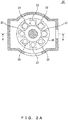
- FIGS. 2A and 2B are views of the filter block switch mechanism of the optical unit closest to the tube lens provided for the microscope illustrated in FIG. 1 .
- FIG. 2A is a sectional view of the section orthogonal to the optical axis of the objective.
- FIG. 2B is a sectional view at the A-A section illustrated in FIG. 2A .
- a microscope 100 exemplified in FIG. 1 is an inverted microscope provided with a plurality of optical units (optical units 10 and 20) between an objective 7 and a tube lens 8.
- the optical unit 10 closest to the objective 7 is an optical unit for introducing the stimulus light in the UV (ultraviolet) area emitted from a stimulus light source 1a in a lamp house 1 to the optical axis of the objective 7 through a lens group 3 in a projector tube 2.
- the stimulus light introduced to the optical unit 10 stimulates a sample through the objective 7.
- the optical unit 10 includes a switch mechanism 19 which a plurality of filter blocks can be mounted on and which selectively arranges one of a plurality of filter blocks on the optical axis of the objective 7, and a plurality of filters provided on the switch mechanism 19.
- a switch mechanism 19 which a plurality of filter blocks can be mounted on and which selectively arranges one of a plurality of filter blocks on the optical axis of the objective 7, and a plurality of filters provided on the switch mechanism 19.
- FIG. 1 only a filter block 11 arranged on the optical axis is illustrated in the plurality of filters provided for the switch mechanism 19.
- the filter block 11 (first filter block) includes a dichroic mirror 11a which reflects the stimulus light in the UV area and passes fluorescence from a sample, an excitation filter 11b, and an emission filter 11c of the same size as the excitation filter 11b.
- the size of the optical filters is a common optical filter size.
- the outer diameter may be 25mm, and the effective diameter (first effective diameter) D1 is 22mm.
- the distance S1 from the dichroic mirror 11a to the excitation filter 11b is approximately equal to the distance S2 from the dichroic mirror 11a to the emission filter 11c, and each of the distances is about 18mm, 15mm.
- the distance L1 from the contact surface of the objective 7 to the intersection of the optical axis and the dichroic mirror 11a is, for example, 70mm, and there is a revolver or an up-and-down mechanism of a revolver between the contact surface and the intersection, although it is not illustrated in the attached drawings.
- the contact surface is a surface of the objective barrel with which the microscope body comes into contact when the objective is attached to the microscope body.
- the contact surface is the basis of a parfocal length.
- the optical unit 20 closest to the tube lens 8 is an optical unit for introducing the excitation light emitted from an excitation light source 4a in a lamp house 4 to the optical axis of the objective 7 through a lens group 6 in a projector tube 5.
- the excitation light introduced to the optical unit 20 is emitted to the entire sample through the objective 7.
- the optical unit 20 includes a switch mechanism 29 which a plurality of filter blocks can be mounted on and which selectively arranges one of a plurality of filter blocks on the optical axis of the objective 7, and a plurality of filter blocks provided for the switch mechanism 29.
- a switch mechanism 29 which a plurality of filter blocks can be mounted on and which selectively arranges one of a plurality of filter blocks on the optical axis of the objective 7, and a plurality of filter blocks provided for the switch mechanism 29.
- FIG. 1 only a filter block 21 arranged on the optical axis is illustrated in the plurality of filters arranged for the switch mechanism 29.
- a plurality of filter blocks 21, 22, 23, 24, 25, 26, 27, and 28 are provided arranged concentrically on the switch mechanism 29 as a turret.
- the filter block 21 (second filter block) includes a dichroic mirror 21a which reflects excitation light and passes the fluorescence from a sample, an excitation filter 21b, an emission filter 21c in the same size as the excitation filter 21b, and a mechanism for adjusting the angle of the dichroic mirror 21a.
- the mechanism for adjusting the angle may be a method of interposing a thin foil between a dichroic mirror and a frame of a filter block, or a mechanism which adjusts the angle of the reflection surface of the dichroic mirror by adjusting a screw unit 21d illustrated in FIG. 1 which presses on the attachment surface of the dichroic mirror formed on the filter block 21 via a plurality of screws.
- the screw directly touches the dichroic mirror to adjust the angle of the reflection surface, but the angle of the attachment surface of the dichroic mirror may be adjusted by the screw to indirectly adjust the angle of the reflection surface.
- the optical filters that is, the excitation filter 21b and the emission filter 21c, are larger than the optical filter included in the filter block 11.
- the outer diameter is 30mm
- the effective diameter (second effective diameter) D2 is 28mm.
- the distance S1 from the dichroic mirror 21a to the excitation filter 21b is 18mm
- the distance S2 from dichroic mirror 21a to the emission filter 21c is 15mm.
- the distance L2 from the contact surface of the objective 7 to the intersection of the optical axis of the objective 7 and the dichroic mirror 21a is, for example, 140mm, and the distance L3 from the contact surface of the objective 7 to the tube lens 8 is, for example, 190mm.
- Each of the filter blocks 22, 23, and 24 includes a dichroic mirror, an excitation filter, and an emission filter, and the size of the dichroic mirror, the excitation filter, and the emission filter of each filter block is the same as the dichroic mirror, the excitation filter, and the emission filter of the filter block 21.
- a filter block 25 (third filter block) includes a dichroic mirror 25a which reflects excitation light and passes the fluorescence from a sample, an excitation filter 25b, and an emission filter 25c which is as large as the excitation filter 25b.
- the optical filters that is, the excitation filters 25b and 25c, are as large as the optical filter included in the filter block 11.
- the outer diameter is 25mm
- the effective diameter (first effective diameter) D1 is 22mm.
- Each of the filter blocks 26, 27, and 28 includes a dichroic mirror, an excitation filter, and an emission filter.
- the dichroic mirror, the excitation filter, and the emission filter of each filter block are as large as the dichroic mirror, the excitation filter, and the emission filter of the filter block 25.
- the switch mechanism 29 is configured to be provided with two types of filter blocks (second filter block, third filter block) having different effective optical filter diameters.
- the two types of filter blocks having different effective optical filter diameters have common-sized attachment units even though the widths of filter blocks are different.
- the position of the optical axis is identical between the two. Therefore, the two types of filter blocks are compatible, and can be replaced with each other.
- the switch mechanism 29 is provided with each four filter blocks of two types.
- the rate between the two types of filter blocks may be arbitrarily changed.
- the switch mechanism 29 may be provided with eight filter blocks having large effective optical filter diameters, and may be provided with eight filter blocks having small optical filter effective diameters. That is, regardless of the type of filter block, the maximum number of filter blocks on switch mechanism 29 to be provided is eight.
- the sizes of two types of filter blocks may be identical, and only the effective diameters of the optical filters may be different from each other.
- the effective diameter of the optical filter in the filter block 21 included in the optical unit 20 closest to the tube lens 8 is configured to be larger than the effective diameter of the optical filter in the filter block 11 included in the optical unit 10 closest to the objective 7.
- the dichroic mirror 21a in the filter block 21 is configured to be larger than the dichroic mirror 11a in the filter block 11.
- the two types of filter blocks having different effective optical filter diameters when the sizes of the two types of filter blocks having different effective optical filter diameters are substantially the same, and the dimension of the attachment unit is common, the two types of filter blocks may be compatible.
- two filter blocks having different effective optical filter diameters may be compatibly provided, and a necessary number of filter blocks of any type may be provided.
- the configuration in which a filter block having a large optical filter is used only when it is necessary to concurrently provide filter blocks having different effective optical filter diameters may be a considerable merit in cost for the user.
- the microscope 100 satisfy the following conditional expression (1), and it is more preferable that the microscope 100 satisfy the conditional expression (2).
- conditional expression (1) indicates an effective diameter of the optical filter in the filter block 11 included in the optical unit 10 closest to the objective 7
- D2 indicates an effective diameter of the optical filter in the filter block 21 included in the optical unit 20 closest to the tube lens 8.
- "f" indicates the focal length of the tube lens 8.
- L1 indicates the distance from the contact surface of the objective 7 to the intersection of the optical axis of the objective 7 and the dichroic mirror 11a
- L2 indicates the distance from the contact surface of the objective 7 to the intersection of the optical axis of the objective 7 and the dichroic mirror 21a.
- the conditional expression (1) regulates the ratio of the effective diameters of the optical filter included in the filter block 11 and the optical filter included in the filter block 21.
- the conditional expression (1) regulates the ratio of the effective diameters of the optical filter included in the filter block 11 and the optical filter included in the filter block 21.
- the conditional expression (2) regulates the effective diameter of an optical filter by considering the interval between the filter block 11 and the filter block 21.
- the obtained value is lower than the lower limit of the conditional expression (2), it is difficult to suppress the vignetting of the off-axis light in the filter block 21 with a microscope having a field number of 18 or more.
- the obtained value is higher than the upper limit of the conditional expression (2), the effective diameter of the optical filter included in the filter block 21 is too large with respect to the effective diameter of the optical filter included in the filter block 11, thereby making it difficult to keep the filter block 11 as large as the filter block 21.
- the dichroic mirror 21a be an octagon with four chamfered corners.
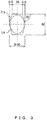
- FIG. 3 is a shape of the dichroic mirror included in the filter block 21.
- FIG. 4 is another shape of the dichroic mirror included in the filter block 21.
- the dichroic mirror 21a by having the dichroic mirror 21a be an octagon with four chamfered corners, the dichroic mirror 21a, which is larger than the dichroic mirror 11a, may be stored in the filter block 21, which is substantially as large as the filter block 11 including the dichroic mirror 11a.
- the sizes of the two types of filter blocks having different optical filter effective diameters may be substantially equal to each other.
- the dichroic mirror 21a Since the dichroic mirror 21a is inclined at 45 degrees with respect to the optical axis, the range LR of the luminous flux which enters the dichroic mirror 21a is oval shaped. Therefore, to maximize the chamfered area (hereafter referred to as a chamfered portion) within the scope of the not-overlapping range LR of the luminous flux, it is preferable that chamfer of the four corners of the dichroic mirror 21a be at a large angle with respect to the short side of the dichroic mirror 21a, which is parallel to the short axis of the oval. Concretely, it is preferable that the chamfering angle be equal to or higher than 55 degrees and equal to or lower than 80 degrees with respect to the short side.
- the filter block 21 may include, in place of a dichroic mirror 21a, a dichroic mirror 31a having the four corners illustrated in FIG. 4 chamfered at a chamfering angle of 60 degrees with respect to the short side.
- the dichroic mirror 21a satisfy the following conditional expression (3) in addition to the condition of the chamfering angle above. 0.3 ⁇ 2 ⁇ C / S ⁇ 0.7
- S indicates the length of the short side (that is, the length of the dichroic mirror 21a in the direction of a short axis) of the dichroic mirror 21a included in the filter block 21 before the chamfering process
- C indicates the length of each chamfered portion in the direction of the short side formed at the four corners of the dichroic mirror 21a included in the filter block 21.
- the conditional expression (3) regulates the ratio of the length of the chamfered portion in the direction of the short side to the length of the short side before the chamfering process. That is, the lower limit of 0.3 indicates the state in which 30% of the short side before the chamfering process is chamfered, and the upper limit of 0.7 indicates the state in which the 70% of the short side before the chamfering process is chamfered.
- the chamfered portion is too small. Therefore, it is difficult to store the dichroic mirror 21a in the filter block 21.
- the chamfered portion is too large, and the chamfered portion overlaps the range LR of the luminous flux. As a result, a portion of incident light bypasses the dichroic mirror 21a without entering the dichroic mirror 21a.
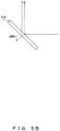
- the filter block 21 is configured to easily reflect the excitation light leaking from the dichroic mirror 21a (hereafter referred to as leakage light) and allow the light to enter the detection optical path. Therefore, as illustrated in FIG. 5B , it is preferable that the filter block 21 include a dichroic mirror 41a both sides of whose substrates are coated with an interference coating instead of the dichroic mirror 21a. Using a dichroic mirror 41a having both sides coated with an interference coating, the light quantity of the leakage light may be suppressed.
- the filter block 21 included in the optical unit 20 closest to the tube lens 8 be provided with a device for rotating the dichroic mirror 21a and adjusting the angle with respect to the optical axis.
- a device for rotating the dichroic mirror 21a and adjusting the angle with respect to the optical axis An example would be a mechanism for changing the angle by pressing the surface of the dichroic mirror by the screw unit 21d. Since the dichroic mirror 21a is farther from the objective 7 than the dichroic mirror 11a, the change in the illumination position is large in accordance with the angle error. Therefore, it is necessary to set the angle of the dichroic mirror 21a with respect to the optical axis with a high accuracy. With the microscope 100, the angle of the dichroic mirror 21a may be appropriately adjusted by providing the angle adjusting mechanism for the dichroic mirror. It is preferable that the mechanism for adjusting the angle of the dichroic mirror be similarly provided for other filter blocks in the optical unit 20.
- the difference in light quantity of the detected light which enters an image pickup element 9 between the case in which the filter block 21 including the optical filter having a large effective diameter is arranged on the optical axis in the optical unit 20 of the microscope 100 according to the present embodiment and the case in which the filter block 25 including the optical filter having a small effective diameter is arranged on the optical axis in the optical unit 20 of the microscope 100 according to the present embodiment is described below with reference to FIGS. 6 , 7A , and 7B .
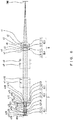
- FIG. 6 is a sectional view of the optical system from the objective to the tube lens of the microscope according to the present embodiment.
- the lens data of the optical system illustrated in FIG. 6 is listed below.
- INF 15.0000 9 INF 55.0000 10
- 3.0324 1.49700 81.54 14 INF 0.1300 15 12.7726 3.2167 1.49700 81.54 16 19.9601 2.7687 1.48749 70.23 17 6.3912 5.6402 18 -8.2650 1.2763 1.55836 54.
- s indicates a surface number
- r indicates the radius (mm) of curvature
- d indicates the surface interval (mm)
- nd indicates the refractive index with respect to the d-line
- vd indicates the Abbe number
- IMG indicates an image plane
- OBJ indicates the sample surface.
- the surface numbers s2 through s7 indicate the lens surfaces of tube lens 8
- the surface numbers s13 through s27 indicate the lens surfaces of the objective 7.
- the surface number s8 indicates the position of the emission filter in the optical unit 20
- the surface number s9 indicates the position of the intersection of the dichroic mirror in the optical unit 20 and the optical axis.
- the surface number s10 indicates the position of the emission filter 11c in the optical unit 10
- the surface number s11 indicates the position of the intersection of the dichroic mirror 11a in the optical unit 10 and the optical axis.
- the surface number s12 indicates the contact surface of the objective 7
- the surface number s28 indicates the surface of the cover glass closest to the objective 7.
- FIG. 7A illustrates the illumination distribution on the image plane when the sample surface becomes evenly luminous in cases where the filter block 11 is arranged on the optical axis in the optical unit 10 and the filter block 25 is arranged on the optical axis in the optical unit 20.
- FIG. 7B illustrates the illumination distribution on the image plane when the sample surface becomes evenly luminous in cases where the filter block 11 is arranged on the optical axis in the optical unit 10 and the filter block 21 is arranged on the optical axis in the optical unit 20.
- the occurrence of the vignetting of the off-axis light is considerably suppressed, and the shortage of the light quantity of the periphery may be improved. As a result, a large observation field may be secured.
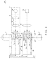
- FIG. 8 is a diagram illustrating a configuration of the microscope according to the present embodiment.
- a microscope 101 exemplified in FIG. 8 is an inverted microscope provided with a plurality of optical units (optical unit 10, optical unit 20) between the objective 7 and the tube lens 8 like the microscope 100 according to embodiment 1 exemplified in FIG. 1 .
- the microscope 101 is different from the microscope 100 in that a tube lens 51 and an image pickup element 52 are provided instead of the lamp house 4 and the projector tube 5, and that the lamp house 4 and the projector tube 5 are provided instead of the lamp house 1 and the projector tube 2. Otherwise, the configuration of the microscope 101 is the same as the configuration of the microscope 100, and the same components are assigned the same reference numerals, and the explanation is omitted here.
- the optical unit 10 closest to the objective 7 is an optical unit which introduces the excitation light emitted from the excitation light source 4a in the lamp house 4 to the optical axis of the objective 7 through the lens group 6 in the projector tube 5.
- the excitation light introduced to the optical unit 10 is emitted to the entire sample through the objective 7, and derives, for example, a fluorescence resonance energy transfer (FRET) event.
- FRET fluorescence resonance energy transfer
- the optical unit 20 closest to the tube lens 8 separates the fluorescence of two wavelengths caused by the FRET event, and introduces the fluorescence of one wavelength to the image pickup element 9 and the fluorescence of the other wavelength to the image pickup element 52. Therefore, with the microscope 101, the excitation filter 21b included in the filter block 21 functions as an emission filter which passes only the fluorescence to be detected.
- the effective diameter of the optical filter in the filter block 21 is larger than the effective diameter of the optical filter in the filter block 11, and the occurrence of the vignetting of the off-axis light in the filter block 21 closest to the tube lens 8 farthest from the objective 7 is suppressed, thereby reducing the degradation of the light quantity of the periphery. Therefore, using the microscope 101, a large observation field may be secured while providing various functions realized by a plurality of optical units, thereby obtaining the effect obtained by the microscope 100 according to embodiment 1.
- the explanation is given with reference to the concrete configurations of a microscope, but the configuration of the microscope is not limited to the configuration of the microscope 100 according to embodiment 1 or the condition of the microscope 101 according to embodiment 2, and a number of variations are realized.
- FIGS. 1 and 8 a microscope provided with two optical units between the objective 7 and the tube lens 8 is exemplified, but the number of optical units is not limited to two.
- the number of optical units may be 2 or more, and an AF optical unit or the like may be further provided.
- FIGS. 1 and 8 a inverted microscope is exemplified.
- the application range of the present invention according to the present embodiment is not limited to the inverted microscope. Any microscope having a plurality of optical units between the objective 7 and the tube lens 8 may be likewise applied to an upright microscope.
- FIGS. 1 and 8 a configuration in which a lamp house is directly connected to a projector tube is exemplified, but an optical filter may be provided between the lamp house and the projector tube to suppress heat conductivity to the body of a microscope.
- a light source it is not limited to a lamp light source, but any light source such as a laser light source or the like may be used.
- the switch mechanism 29 as a turret system is exemplified as a switch mechanism for switching filter blocks, the switch mechanism is not limited to the turret system, but may be, for example, a sliding switch mechanism provided with a plurality of filter blocks.
- a switch mechanism 29 which may be provided with eight filter blocks is exemplified, but the switch mechanism may be provided with a plurality of filter blocks, and it is more preferable that six or more filter blocks be provided.
- a filter block includes a dichroic mirror larger than a common dichroic mirror (hereafter referred to as an XL mirror)
- the filter block itself becomes larger. Therefore, the maximum number of filter blocks provided for a switch mechanism is different between the filter blocks of normal size and the filter blocks including the XL mirror.
- the same number of filter blocks are provided for a switch mechanism independently of the size of a dichroic mirror by maintaining the same size of filter blocks independently of the size of a dichroic mirror.
- optical unit 10 and the optical unit 20 may be configured as attachable to and detachable from the body of a microscope.
- optical unit 10 and the optical unit 20 may be appropriately added as necessary, or one of them may be removed.
- a filter block may be appropriately replaced.
- a projector tube, an observation optical system, etc. attached to an optical unit is configured as attachable and detachable.
- a filter block may be selected according to the positions of the projector tube and the observation optical system provided for a plurality of optical units, and according to the type of observation optical system.
Landscapes
- Physics & Mathematics (AREA)
- Chemical & Material Sciences (AREA)
- Analytical Chemistry (AREA)
- General Physics & Mathematics (AREA)
- Optics & Photonics (AREA)
- Microscoopes, Condenser (AREA)
- Lens Barrels (AREA)
- Automatic Focus Adjustment (AREA)
Description
- The present invention is related to a microscope provided with a plurality of optical units for autofocus (hereafter referred to as AF), observation, light stimulus, etc., each including a filter block.
- In the field of biomicroscopes, there is a well known microscope having various functions including not only the function of illuminating and observing a cultivated sample, but also the function of stimulating the cultivated sample with light and the AF function of correcting an out-of-focus image to observe the cultivated sample for a long time.
- The various functions are realized by providing between an objective and a tube lens an optical unit for light stimulus to introduce stimulus light to the optical axis and for AF to introduce autofocus light to the optical axis of an objective in addition to an optical unit for a fluorescent observation conventionally provided to introduce excitation light to the optical axis of an objective.
- The microscope provided with a plurality of optical units between an objective and a tube lens is disclosed by, for example, Japanese Laid-open Patent Publication No.
2006-091723 2006-091723 - Further, from
EP 1 582 904 A1 - With the microscope provided with an infinity-corrected objective, on-axis light is emitted as luminous flux parallel to an optical axis from an objective to a tube lens while off-axis
light is emitted as parallel flux inclined with respect to the optical axis from the objective to the tube lens. - Therefore, if the distance between the objective and the tube lens is made to be long to provide between the objective and the tube lens a plurality of optical units for inputting and outputting light for observation and illumination, then vignetting occurs on the off-axis light in optical units which are remote from the objective. As a result, since peripheral light quantity becomes short and a peripheral area is darkly observed, it is hard to secure a large observation field.
- The above-mentioned event occurs not only with detection light, but also with illumination light. Therefore, the light introduced from the optical unit which is remote from the objective does not brightly illuminate the surrounding area, which also makes it difficult to secure a large observation field.
- In this situation, the present invention aims at providing a microscope which has a large observation field, and is provided with a plurality of optical units.
- The first aspect of the present invention is to provide a microscope having a plurality of optical units each including a filter block between an objective and a tube lens. Among the plurality of optical units, the optical unit closest to the objective includes a first filter block provided with an optical filter having a first effective diameter. Among the plurality of optical units, the optical unit closest to the tube lens includes a second filter block provided with an optical filter having a second effective diameter larger than the first effective diameter.
- The present invention will be more apparent from the following detailed description when the accompanying drawings are referenced.
-
FIG. 1 is a diagram illustrating a configuration of the microscope according toembodiment 1 of the present invention; -
FIG. 2A is a sectional view of the section, which is orthogonal to the optical axis, of the filter block switch mechanism of the optical unit closest to the tube lens illustrated inFIG. 1 ; -
FIG. 2B is a sectional view at the A-A section illustrated inFIG. 2A of the filter block switch mechanism of the optical unit closest to the tube lens illustrated inFIG. 1 ; -
FIG. 3 illustrates the shape of the dichroic mirror included in the optical unit closest to the tube lens illustrated inFIG. 1 ; -
FIG. 4 illustrates another shape of the dichroic mirror included in the optical unit closest to the tube lens illustrated inFIG. 1 ; -
FIG. 5A is an explanatory view of the leakage light caused by the dichroic mirror included in the optical unit closest to the tube lens illustrated inFIG. 1 ; -
FIG. 5B is an explanatory view of a variation example of the dichroic mirror included in the optical unit closest to the tube lens illustrated inFIG. 1 ; -
FIG. 6 is a sectional view of the optical system from the objective to the tube lens of the microscope illustrated inFIG. 1 ; -
FIG. 7A is a view of the distribution of the light quantity on the image plane when the filter block provided in the optical unit closest to the tube lens illustrated inFIG. 1 includes an optical filter having a small effective diameter ; -
FIG. 7B is a view of the distribution of the light quantity on the image plane when the filter block provided in the optical unit closest to the tube lens illustrated inFIG. 1 includes an optical filter having a large effective diameter ; and -
FIG. 8 is a diagram illustrating a configuration of the microscope according toembodiment 2 of the present invention. -
FIG. 1 is a diagram illustrating a configuration of the microscope according toembodiment 1 of the present invention.FIGS. 2A and2B are views of the filter block switch mechanism of the optical unit closest to the tube lens provided for the microscope illustrated inFIG. 1 .FIG. 2A is a sectional view of the section orthogonal to the optical axis of the objective.FIG. 2B is a sectional view at the A-A section illustrated inFIG. 2A . - A
microscope 100 exemplified inFIG. 1 is an inverted microscope provided with a plurality of optical units (optical units 10 and 20) between an objective 7 and atube lens 8. - The
optical unit 10 closest to the objective 7 is an optical unit for introducing the stimulus light in the UV (ultraviolet) area emitted from astimulus light source 1a in alamp house 1 to the optical axis of theobjective 7 through alens group 3 in aprojector tube 2. The stimulus light introduced to theoptical unit 10 stimulates a sample through theobjective 7. - The
optical unit 10 includes aswitch mechanism 19 which a plurality of filter blocks can be mounted on and which selectively arranges one of a plurality of filter blocks on the optical axis of theobjective 7, and a plurality of filters provided on theswitch mechanism 19. InFIG. 1 , only afilter block 11 arranged on the optical axis is illustrated in the plurality of filters provided for theswitch mechanism 19. - The filter block 11 (first filter block) includes a
dichroic mirror 11a which reflects the stimulus light in the UV area and passes fluorescence from a sample, anexcitation filter 11b, and anemission filter 11c of the same size as theexcitation filter 11b. - The size of the optical filters, that is, the
excitation filter 11b and theemission filter 11c, is a common optical filter size. For example, the outer diameter may be 25mm, and the effective diameter (first effective diameter) D1 is 22mm. The size of thedichroic mirror 11a is a common dichroic mirror size. For example, it may be (short side x long side x thickness) = (26mm x 36mm x 1mm). The distance S1 from thedichroic mirror 11a to theexcitation filter 11b is approximately equal to the distance S2 from thedichroic mirror 11a to theemission filter 11c, and each of the distances is about 18mm, 15mm. The distance L1 from the contact surface of theobjective 7 to the intersection of the optical axis and thedichroic mirror 11a is, for example, 70mm, and there is a revolver or an up-and-down mechanism of a revolver between the contact surface and the intersection, although it is not illustrated in the attached drawings. - Note that the contact surface is a surface of the objective barrel with which the microscope body comes into contact when the objective is attached to the microscope body. The contact surface is the basis of a parfocal length.
- The
optical unit 20 closest to thetube lens 8 is an optical unit for introducing the excitation light emitted from anexcitation light source 4a in alamp house 4 to the optical axis of theobjective 7 through alens group 6 in aprojector tube 5. The excitation light introduced to theoptical unit 20 is emitted to the entire sample through theobjective 7. - The
optical unit 20 includes aswitch mechanism 29 which a plurality of filter blocks can be mounted on and which selectively arranges one of a plurality of filter blocks on the optical axis of theobjective 7, and a plurality of filter blocks provided for theswitch mechanism 29. InFIG. 1 , only afilter block 21 arranged on the optical axis is illustrated in the plurality of filters arranged for theswitch mechanism 29. - In more detail, in the
optical unit 20, as exemplified inFIGS. 2A and2B , a plurality of filter blocks 21, 22, 23, 24, 25, 26, 27, and 28 are provided arranged concentrically on theswitch mechanism 29 as a turret. - The filter block 21 (second filter block) includes a
dichroic mirror 21a which reflects excitation light and passes the fluorescence from a sample, anexcitation filter 21b, anemission filter 21c in the same size as theexcitation filter 21b, and a mechanism for adjusting the angle of thedichroic mirror 21a. The mechanism for adjusting the angle may be a method of interposing a thin foil between a dichroic mirror and a frame of a filter block, or a mechanism which adjusts the angle of the reflection surface of the dichroic mirror by adjusting ascrew unit 21d illustrated inFIG. 1 which presses on the attachment surface of the dichroic mirror formed on thefilter block 21 via a plurality of screws. InFIG. 1 , the screw directly touches the dichroic mirror to adjust the angle of the reflection surface, but the angle of the attachment surface of the dichroic mirror may be adjusted by the screw to indirectly adjust the angle of the reflection surface. - The optical filters, that is, the
excitation filter 21b and theemission filter 21c, are larger than the optical filter included in thefilter block 11. For example, the outer diameter is 30mm, and the effective diameter (second effective diameter) D2 is 28mm. Thedichroic mirror 21a is larger than thedichroic mirror 11a included in thefilter block 11, and is, for example, (short side × long side × thickness) = (30mm × 42mm × 1mm). The distance S1 from thedichroic mirror 21a to theexcitation filter 21b is 18mm, and the distance S2 fromdichroic mirror 21a to theemission filter 21c is 15mm. The distance L2 from the contact surface of theobjective 7 to the intersection of the optical axis of theobjective 7 and thedichroic mirror 21a is, for example, 140mm, and the distance L3 from the contact surface of theobjective 7 to thetube lens 8 is, for example, 190mm. - Each of the filter blocks 22, 23, and 24 includes a dichroic mirror, an excitation filter, and an emission filter, and the size of the dichroic mirror, the excitation filter, and the emission filter of each filter block is the same as the dichroic mirror, the excitation filter, and the emission filter of the
filter block 21. - A filter block 25 (third filter block) includes a
dichroic mirror 25a which reflects excitation light and passes the fluorescence from a sample, anexcitation filter 25b, and anemission filter 25c which is as large as theexcitation filter 25b. - The optical filters, that is, the excitation filters 25b and 25c, are as large as the optical filter included in the
filter block 11. For example, the outer diameter is 25mm, and the effective diameter (first effective diameter) D1 is 22mm. Thedichroic mirror 25a is as large as thedichroic mirror 11a included in thefilter block 11. For example, it is (short side × long side × thickness) = (26mm × 36mm × 1mm). - Each of the filter blocks 26, 27, and 28 includes a dichroic mirror, an excitation filter, and an emission filter. The dichroic mirror, the excitation filter, and the emission filter of each filter block are as large as the dichroic mirror, the excitation filter, and the emission filter of the
filter block 25. - That is, the
switch mechanism 29 is configured to be provided with two types of filter blocks (second filter block, third filter block) having different effective optical filter diameters. - The two types of filter blocks having different effective optical filter diameters have common-sized attachment units even though the widths of filter blocks are different. As illustrated in
FIG. 1 , the position of the optical axis is identical between the two. Therefore, the two types of filter blocks are compatible, and can be replaced with each other. Accordingly, inFIG. 2A , theswitch mechanism 29 is provided with each four filter blocks of two types. The rate between the two types of filter blocks may be arbitrarily changed. For example, theswitch mechanism 29 may be provided with eight filter blocks having large effective optical filter diameters, and may be provided with eight filter blocks having small optical filter effective diameters. That is, regardless of the type of filter block, the maximum number of filter blocks onswitch mechanism 29 to be provided is eight. - The sizes of two types of filter blocks may be identical, and only the effective diameters of the optical filters may be different from each other.
- In the
microscope 100 configured as described above, the effective diameter of the optical filter in thefilter block 21 included in theoptical unit 20 closest to thetube lens 8 is configured to be larger than the effective diameter of the optical filter in thefilter block 11 included in theoptical unit 10 closest to theobjective 7. Also thedichroic mirror 21a in thefilter block 21 is configured to be larger than thedichroic mirror 11a in thefilter block 11. Thus, the occurrence of the vignetting of the off-axis light in thefilter block 21 closest to thetube lens 8 which is farthest from theobjective 7 is suppressed, thereby reducing the degradation of the peripheral light quantity. Therefore, in themicroscope 100, a large observation field may be secured with various functions which are realized by a plurality of optical units. - Also with the
microscope 100, when the sizes of the two types of filter blocks having different effective optical filter diameters are substantially the same, and the dimension of the attachment unit is common, the two types of filter blocks may be compatible. Thus, two filter blocks having different effective optical filter diameters may be compatibly provided, and a necessary number of filter blocks of any type may be provided. By considering that a filter block having an optical filter larger than a common size is more expensive, and that there is a strong likelihood that a user has a filter block having a common size optical filter, the configuration in which a filter block having a large optical filter is used only when it is necessary to concurrently provide filter blocks having different effective optical filter diameters may be a considerable merit in cost for the user. - To efficiently suppress the occurrence of vignetting of off-axis light in the
filter block 21, and secure the compatibility between thefilter block 11 having a common size optical filter and thefilter block 21 having a large optical filter, it is preferable that themicroscope 100 satisfy the following conditional expression (1), and it is more preferable that themicroscope 100 satisfy the conditional expression (2).

filter block 11 included in theoptical unit 10 closest to theobjective 7, and D2 indicates an effective diameter of the optical filter in thefilter block 21 included in theoptical unit 20 closest to thetube lens 8. "f" indicates the focal length of thetube lens 8. L1 indicates the distance from the contact surface of theobjective 7 to the intersection of the optical axis of theobjective 7 and thedichroic mirror 11a, and L2 indicates the distance from the contact surface of theobjective 7 to the intersection of the optical axis of theobjective 7 and thedichroic mirror 21a. - The conditional expression (1) regulates the ratio of the effective diameters of the optical filter included in the
filter block 11 and the optical filter included in thefilter block 21. When the obtained value is lower than the lower limit of the conditional expression (1), there is almost no effect of suppressing the vignetting of the off-axis light in thefilter block 21. On the other hand, when the obtained value is higher than the upper limit of the conditional expression (1), the effective diameter of the optical filter included in thefilter block 21 is too large with respect to the effective diameter of the optical filter included in thefilter block 11, thereby making it difficult to keep thefilter block 11 as large as thefilter block 21. - The conditional expression (2) regulates the effective diameter of an optical filter by considering the interval between the
filter block 11 and thefilter block 21. When the obtained value is lower than the lower limit of the conditional expression (2), it is difficult to suppress the vignetting of the off-axis light in thefilter block 21 with a microscope having a field number of 18 or more. On the other hand, when the obtained value is higher than the upper limit of the conditional expression (2), the effective diameter of the optical filter included in thefilter block 21 is too large with respect to the effective diameter of the optical filter included in thefilter block 11, thereby making it difficult to keep thefilter block 11 as large as thefilter block 21. - In the case of the
microscope 100 exemplified inFIG. 1 , since the effective diameter D1 = 22mm, the effective diameter D2 = 28mm, and D2/D1 = 1.27, the conditional expression (1) is satisfied. In addition, the distance L1 = 70mm, the distance L2 = 140mm, the focal length f = 180mm, and f × (D2 - D1) / (L2 - L1) = 15.4, and the conditional expression (2) is satisfied. - Furthermore, to secure the compatibility between the
filter block 11 including the common-sizedichroic mirror 11a and thefilter block 21 including the large-sizedichroic mirror 21a, it is preferable that thedichroic mirror 21a be an octagon with four chamfered corners. -
FIG. 3 is a shape of the dichroic mirror included in thefilter block 21.FIG. 4 is another shape of the dichroic mirror included in thefilter block 21. As illustrated inFIG. 3 , by having thedichroic mirror 21a be an octagon with four chamfered corners, thedichroic mirror 21a, which is larger than thedichroic mirror 11a, may be stored in thefilter block 21, which is substantially as large as thefilter block 11 including thedichroic mirror 11a. Thus, the sizes of the two types of filter blocks having different optical filter effective diameters may be substantially equal to each other. - Since the
dichroic mirror 21a is inclined at 45 degrees with respect to the optical axis, the range LR of the luminous flux which enters thedichroic mirror 21a is oval shaped. Therefore, to maximize the chamfered area (hereafter referred to as a chamfered portion) within the scope of the not-overlapping range LR of the luminous flux, it is preferable that chamfer of the four corners of thedichroic mirror 21a be at a large angle with respect to the short side of thedichroic mirror 21a, which is parallel to the short axis of the oval. Concretely, it is preferable that the chamfering angle be equal to or higher than 55 degrees and equal to or lower than 80 degrees with respect to the short side. Therefore, although thedichroic mirror 21a is exemplified inFIG. 3 , with the four corners chamfered at a chamfering angle of 75 degrees with respect to the short side, thefilter block 21 may include, in place of adichroic mirror 21a, adichroic mirror 31a having the four corners illustrated inFIG. 4 chamfered at a chamfering angle of 60 degrees with respect to the short side. - Furthermore, although the chamfering angle satisfies the conditions above, the chamfered portion is not necessarily large. Therefore, it is preferable that the
dichroic mirror 21a satisfy the following conditional expression (3) in addition to the condition of the chamfering angle above.
dichroic mirror 21a in the direction of a short axis) of thedichroic mirror 21a included in thefilter block 21 before the chamfering process, and C indicates the length of each chamfered portion in the direction of the short side formed at the four corners of thedichroic mirror 21a included in thefilter block 21. - The conditional expression (3) regulates the ratio of the length of the chamfered portion in the direction of the short side to the length of the short side before the chamfering process. That is, the lower limit of 0.3 indicates the state in which 30% of the short side before the chamfering process is chamfered, and the upper limit of 0.7 indicates the state in which the 70% of the short side before the chamfering process is chamfered.
- If the obtained value is lower than the lower limit of the conditional expression (3), the chamfered portion is too small. Therefore, it is difficult to store the
dichroic mirror 21a in thefilter block 21. On the other hand, if the obtained value exceeds the upper limit of the conditional expression (3), the chamfered portion is too large, and the chamfered portion overlaps the range LR of the luminous flux. As a result, a portion of incident light bypasses thedichroic mirror 21a without entering thedichroic mirror 21a. - In the case of the
dichroic mirror 21a exemplified inFIG. 3 , the length S of the short side is 30mm and the length C of the chamfered portion in the direction of the short side is 5mm, thereby obtaining 2 x C/S = 0.33 and satisfying the conditional expression (3). In addition, in the case of thedichroic mirror 31a exemplified inFIG. 4 , the length S of the short side is 30mm, and the length C of the chamfered portion in the direction of the short side is 9mm, thereby obtaining 2 x C/S = 0.6 and satisfying the conditional expression (3). - Furthermore, as illustrated in
FIG. 5A , since the optical filter is larger than the conventional filter, thefilter block 21 is configured to easily reflect the excitation light leaking from thedichroic mirror 21a (hereafter referred to as leakage light) and allow the light to enter the detection optical path. Therefore, as illustrated inFIG. 5B , it is preferable that thefilter block 21 include adichroic mirror 41a both sides of whose substrates are coated with an interference coating instead of thedichroic mirror 21a. Using adichroic mirror 41a having both sides coated with an interference coating, the light quantity of the leakage light may be suppressed. - In addition, as illustrated in
FIG. 1 , it is preferable that thefilter block 21 included in theoptical unit 20 closest to thetube lens 8 be provided with a device for rotating thedichroic mirror 21a and adjusting the angle with respect to the optical axis. An example would be a mechanism for changing the angle by pressing the surface of the dichroic mirror by thescrew unit 21d. Since thedichroic mirror 21a is farther from theobjective 7 than thedichroic mirror 11a, the change in the illumination position is large in accordance with the angle error. Therefore, it is necessary to set the angle of thedichroic mirror 21a with respect to the optical axis with a high accuracy. With themicroscope 100, the angle of thedichroic mirror 21a may be appropriately adjusted by providing the angle adjusting mechanism for the dichroic mirror. It is preferable that the mechanism for adjusting the angle of the dichroic mirror be similarly provided for other filter blocks in theoptical unit 20. - The difference in light quantity of the detected light which enters an
image pickup element 9 between the case in which thefilter block 21 including the optical filter having a large effective diameter is arranged on the optical axis in theoptical unit 20 of themicroscope 100 according to the present embodiment and the case in which thefilter block 25 including the optical filter having a small effective diameter is arranged on the optical axis in theoptical unit 20 of themicroscope 100 according to the present embodiment is described below with reference toFIGS. 6 ,7A , and7B . -
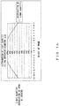
FIG. 6 is a sectional view of the optical system from the objective to the tube lens of the microscope according to the present embodiment. The lens data of the optical system illustrated inFIG. 6 is listed below.s r d nd vd IMG INF 148.3305 1 INF 8.7111 2 -40.6619 3.0298 1.64450 40.82 3 50.7100 6.0238 1.83400 37.16 4 -84.3099 0.6973 5 102.8477 3.4742 1.80610 40.92 6 37.5679 7.7321 1.48749 70.23 7 -68.7541 35.0000 8 INF 15.0000 9 INF 55.0000 10 INF 15.0000 11 INF 70.0000 12 INF -3.9523 13 16.8356 3.0324 1.49700 81.54 14 INF 0.1300 15 12.7726 3.2167 1.49700 81.54 16 19.9601 2.7687 1.48749 70.23 17 6.3912 5.6402 18 -8.2650 1.2763 1.55836 54.01 19 9.8106 3.6739 1.43875 94.93 20 -10.2087 6.5068 21 INF 4.5781 1.43875 94.93 22 -11.8739 1.1100 23 35.6271 4.0793 1.56907 71.30 24 -83.9358 0.2125 25 9.2112 2.7505 1.49700 81.54 26 -55.2737 6.0670 1.67300 38.15 27 10.0179 3.8000 28 INF 0.1700 1.52100 56.02 OBJ INF - In the list above, "s" indicates a surface number, "r" indicates the radius (mm) of curvature, "d" indicates the surface interval (mm), "nd" indicates the refractive index with respect to the d-line, and "vd" indicates the Abbe number. "IMG" indicates an image plane, and "OBJ" indicates the sample surface. The surface numbers s2 through s7 indicate the lens surfaces of
tube lens 8, and the surface numbers s13 through s27 indicate the lens surfaces of theobjective 7. The surface number s8 indicates the position of the emission filter in theoptical unit 20, and the surface number s9 indicates the position of the intersection of the dichroic mirror in theoptical unit 20 and the optical axis. The surface number s10 indicates the position of theemission filter 11c in theoptical unit 10, and the surface number s11 indicates the position of the intersection of thedichroic mirror 11a in theoptical unit 10 and the optical axis. The surface number s12 indicates the contact surface of theobjective 7, and the surface number s28 indicates the surface of the cover glass closest to theobjective 7. -
FIG. 7A illustrates the illumination distribution on the image plane when the sample surface becomes evenly luminous in cases where thefilter block 11 is arranged on the optical axis in theoptical unit 10 and thefilter block 25 is arranged on the optical axis in theoptical unit 20.FIG. 7B illustrates the illumination distribution on the image plane when the sample surface becomes evenly luminous in cases where thefilter block 11 is arranged on the optical axis in theoptical unit 10 and thefilter block 21 is arranged on the optical axis in theoptical unit 20. - As illustrated in
FIG. 7A , when optical filters of the same size are used in theoptical unit 10 closest to theobjective 7 and theoptical unit 20 closest to thetube lens 8, a light quantity of only about 56% is detected on the periphery of the field of thefield number 22, that is, the image height of 11, relative to the central portion. On the other hand, as illustrated inFIG. 7B , when optical filters of different sizes are used between theoptical unit 10 closest to theobjective 7 and theoptical unit 20 closest to thetube lens 8, a light quantity of about 84% may be detected on the periphery of the field of thefield number 22 relative to the central portion. - Thus, using different optical filter sizes between the
optical unit 10 closest to theobjective 7 and theoptical unit 20 closest to thetube lens 8, the occurrence of the vignetting of the off-axis light is considerably suppressed, and the shortage of the light quantity of the periphery may be improved. As a result, a large observation field may be secured. -
FIG. 8 is a diagram illustrating a configuration of the microscope according to the present embodiment. Amicroscope 101 exemplified inFIG. 8 is an inverted microscope provided with a plurality of optical units (optical unit 10, optical unit 20) between the objective 7 and thetube lens 8 like themicroscope 100 according toembodiment 1 exemplified inFIG. 1 . - The
microscope 101 is different from themicroscope 100 in that atube lens 51 and animage pickup element 52 are provided instead of thelamp house 4 and theprojector tube 5, and that thelamp house 4 and theprojector tube 5 are provided instead of thelamp house 1 and theprojector tube 2. Otherwise, the configuration of themicroscope 101 is the same as the configuration of themicroscope 100, and the same components are assigned the same reference numerals, and the explanation is omitted here. - The
optical unit 10 closest to theobjective 7 is an optical unit which introduces the excitation light emitted from theexcitation light source 4a in thelamp house 4 to the optical axis of theobjective 7 through thelens group 6 in theprojector tube 5. The excitation light introduced to theoptical unit 10 is emitted to the entire sample through theobjective 7, and derives, for example, a fluorescence resonance energy transfer (FRET) event. - The
optical unit 20 closest to thetube lens 8 separates the fluorescence of two wavelengths caused by the FRET event, and introduces the fluorescence of one wavelength to theimage pickup element 9 and the fluorescence of the other wavelength to theimage pickup element 52. Therefore, with themicroscope 101, theexcitation filter 21b included in thefilter block 21 functions as an emission filter which passes only the fluorescence to be detected. - Also with the
microscope 101, like themicroscope 100 according toembodiment 1 of the present invention, the effective diameter of the optical filter in thefilter block 21 is larger than the effective diameter of the optical filter in thefilter block 11, and the occurrence of the vignetting of the off-axis light in thefilter block 21 closest to thetube lens 8 farthest from theobjective 7 is suppressed, thereby reducing the degradation of the light quantity of the periphery. Therefore, using themicroscope 101, a large observation field may be secured while providing various functions realized by a plurality of optical units, thereby obtaining the effect obtained by themicroscope 100 according toembodiment 1. - In
embodiments microscope 100 according toembodiment 1 or the condition of themicroscope 101 according toembodiment 2, and a number of variations are realized. - In
FIGS. 1 and8 , a microscope provided with two optical units between the objective 7 and thetube lens 8 is exemplified, but the number of optical units is not limited to two. The number of optical units may be 2 or more, and an AF optical unit or the like may be further provided. - In addition, in
FIGS. 1 and8 , a inverted microscope is exemplified. However, the application range of the present invention according to the present embodiment is not limited to the inverted microscope. Any microscope having a plurality of optical units between the objective 7 and thetube lens 8 may be likewise applied to an upright microscope. - Also in
FIGS. 1 and8 , a configuration in which a lamp house is directly connected to a projector tube is exemplified, but an optical filter may be provided between the lamp house and the projector tube to suppress heat conductivity to the body of a microscope. Furthermore, as for a light source, it is not limited to a lamp light source, but any light source such as a laser light source or the like may be used. - Furthermore, in
FIGS. 2A and2B , theswitch mechanism 29 as a turret system is exemplified as a switch mechanism for switching filter blocks, the switch mechanism is not limited to the turret system, but may be, for example, a sliding switch mechanism provided with a plurality of filter blocks. - In
FIG. 2A , aswitch mechanism 29 which may be provided with eight filter blocks is exemplified, but the switch mechanism may be provided with a plurality of filter blocks, and it is more preferable that six or more filter blocks be provided. Conventionally, when a filter block includes a dichroic mirror larger than a common dichroic mirror (hereafter referred to as an XL mirror), the filter block itself becomes larger. Therefore, the maximum number of filter blocks provided for a switch mechanism is different between the filter blocks of normal size and the filter blocks including the XL mirror. However, according to the microscope of each embodiment of the present invention, the same number of filter blocks are provided for a switch mechanism independently of the size of a dichroic mirror by maintaining the same size of filter blocks independently of the size of a dichroic mirror. - Furthermore, the
optical unit 10 and theoptical unit 20 may be configured as attachable to and detachable from the body of a microscope. - In addition, the
optical unit 10 and theoptical unit 20 may be appropriately added as necessary, or one of them may be removed. - With a plurality of optical units, since the configuration of a switch mechanism is common, the filter block provided for a switch mechanism may be appropriately replaced. Furthermore, a projector tube, an observation optical system, etc. attached to an optical unit is configured as attachable and detachable. With an optical unit, a filter block may be selected according to the positions of the projector tube and the observation optical system provided for a plurality of optical units, and according to the type of observation optical system.
Claims (11)
- A microscope (100, 101) having a plurality of optical units (10, 20) each including a filter block (11, 21) between an objective (7) and a tube lens (8, 51),
an optical unit (10) closest to the objective (7) in the plurality of optical units (10, 20), having a first filter block (11) provided with an optical filter (11b, 11c) which has a first effective diameter; and
an optical unit (20) closest to the tube lens (8) in the plurality of optical units (10, 20), having a second filter block (21) provided with an optical filter (21b, 21c) which has a second effective diameter, characterized in that the second effective diameter is larger than the first effective diameter. - The microscope (100, 101) according to claim 1 wherein
each of the plurality of filter blocks (11, 21) includes an optical filter (11b, 11c, 21b, 21c) and a dichroic mirror (11a, 21a). - The microscope (100, 101) according to claim 2, wherein the microscope satisfies the condition:

- The microscope (100, 101) according to claim 3, wherein the microscope satisfies the condition :

where f indicates a focal length of the tube lens (8), L1 indicates a distance from an contact surface of the objective (7) to an intersection of an optical axis of the objective (7) and a dichroic mirror (11a) included in the first filter block (11), and L2 indicates a distance from an contact surface of the objective (7) to an intersection of an optical axis of the objective (7) and a dichroic mirror (21a) included in the second filter block (21). - The microscope (100, 101) according to claim 2, wherein
a dichroic mirror (21a) included in the second filter block (21) is an octagon having four chamfered corners. - The microscope (100,101) according to claim 5, wherein:when a chamfering angle of a dichroic mirror (21a) included in the second filter block (21) is equal to or higher than 55 degrees and equal to or lower than 80 degrees; andthe microscope satisfies the condition:

- The microscope (100, 101) according to claim 5, wherein
the optical unit (20) closest to the tube lens (8) in the plurality of optical units (10, 20) is provided with a plurality of filter blocks (21, 22, 23, 24, 25, 26, 27, 28), and comprises a switch mechanism (29) for selectively arranging one of the plurality of filter blocks (21, 22, 23, 24, 25, 26, 27, 28) on an optical axis of the objective (8); and
the switch mechanism (29) is provided with two type of filter blocks (21, 22, 23, 24, 25, 26, 27, 28), that is, the second filter block (21, 22, 23, 24) including an optical filter having the second effective diameter and a third filter block (25, 26, 27, 28) including an optical filter having the first effective diameter. - The microscope (100, 101) according to claim 7, wherein
a maximum number of filter blocks provided for the switch mechanism (29) when only the second filter block is provided is equal to a maximum number of filter blocks provided for the switch mechanism (29) when only the third filter block is provided. - The microscope (100, 101) according to claim 8, wherein
the optical unit (10) closest to the objective (7) in the plurality of optical units is provided with a plurality of filter blocks, and comprises a switch mechanism (19) for selectively arranging one of the plurality of filter blocks on an optical axis of the objective (7). - The microscope (100, 101) according to claim 2, wherein
a dichroic mirror (41a) included in the second filter block (21) is coated with an interference coating on both sides of a substrate. - The microscope (100, 101) according to claim 2, further comprising
a device (21d) configured to adjust a tilt of a dichroic mirror (21a) included in the second filter block (21).
Applications Claiming Priority (1)
| Application Number | Priority Date | Filing Date | Title |
|---|---|---|---|
| JP2012057838A JP5988629B2 (en) | 2012-03-14 | 2012-03-14 | Microscope with multiple optical units |
Publications (2)
| Publication Number | Publication Date |
|---|---|
| EP2660640A1 EP2660640A1 (en) | 2013-11-06 |
| EP2660640B1 true EP2660640B1 (en) | 2017-05-03 |
Family
ID=47632895
Family Applications (1)
| Application Number | Title | Priority Date | Filing Date |
|---|---|---|---|
| EP13153597.3A Revoked EP2660640B1 (en) | 2012-03-14 | 2013-02-01 | Microscope provided with plural optical units |
Country Status (3)
| Country | Link |
|---|---|
| US (1) | US9851547B2 (en) |
| EP (1) | EP2660640B1 (en) |
| JP (1) | JP5988629B2 (en) |
Families Citing this family (3)
| Publication number | Priority date | Publication date | Assignee | Title |
|---|---|---|---|---|
| DE102014110575B4 (en) | 2014-07-25 | 2017-10-12 | Leica Microsystems Cms Gmbh | Microscope and method for optically examining and / or manipulating a microscopic sample |
| JP6746376B2 (en) * | 2016-05-23 | 2020-08-26 | 株式会社ミツトヨ | Switching method of measurement system and setting value for adjustment |
| CN112823316B (en) * | 2018-08-29 | 2022-08-05 | 公立大学法人兵库县立大学 | Holographic imaging device and holographic imaging method |
Citations (8)
| Publication number | Priority date | Publication date | Assignee | Title |
|---|---|---|---|---|
| US6414805B1 (en) | 1999-12-07 | 2002-07-02 | Chroma Technology Corp. | Reflected-light type fluorescence microscope and filter cassette used therefor |
| US20050068614A1 (en) | 2003-09-29 | 2005-03-31 | Olympus Corporation | Microscope system and microscope focus maintaining device for the same |
| US20050161593A1 (en) | 2003-11-21 | 2005-07-28 | Olympus Corporation | Confocal laser scanning microscope |
| EP1582904A1 (en) | 2004-03-30 | 2005-10-05 | Olympus Corporation | System microscope |
| US20050227231A1 (en) | 2001-10-04 | 2005-10-13 | Dimitri Tcherkassov | Device for sequencing nucleic acid molecules |
| US20060007343A1 (en) | 2004-07-06 | 2006-01-12 | Martin Thomas | Optical imaging device |
| EP1640759A1 (en) | 2004-09-27 | 2006-03-29 | Olympus Corporation | Inverted microscope |
| US20090284833A1 (en) | 2008-05-14 | 2009-11-19 | Olympus Corporation | Microscope illumination device |
Family Cites Families (7)
| Publication number | Priority date | Publication date | Assignee | Title |
|---|---|---|---|---|
| JP2600573Y2 (en) * | 1993-03-24 | 1999-10-12 | オリンパス光学工業株式会社 | Filter block |
| US6631226B1 (en) * | 1997-01-27 | 2003-10-07 | Carl Zeiss Jena Gmbh | Laser scanning microscope |
| JP4222664B2 (en) * | 1997-10-24 | 2009-02-12 | オリンパス株式会社 | Epi-illumination microscope |
| US6075643A (en) | 1997-10-24 | 2000-06-13 | Olympus Optical Co., Ltd. | Reflected fluorescence microscope with multiple laser and excitation light sources |
| JP2008276070A (en) * | 2007-05-02 | 2008-11-13 | Olympus Corp | Magnifying image pickup apparatus |
| JP5536995B2 (en) | 2007-07-17 | 2014-07-02 | オリンパス株式会社 | Microscope objective lens and laser scanning microscope system |
| JP5321305B2 (en) * | 2009-07-15 | 2013-10-23 | 株式会社ニコン | Scanning microscope |
-
2012
- 2012-03-14 JP JP2012057838A patent/JP5988629B2/en active Active
-
2013
- 2013-01-29 US US13/752,991 patent/US9851547B2/en active Active
- 2013-02-01 EP EP13153597.3A patent/EP2660640B1/en not_active Revoked
Patent Citations (8)
| Publication number | Priority date | Publication date | Assignee | Title |
|---|---|---|---|---|
| US6414805B1 (en) | 1999-12-07 | 2002-07-02 | Chroma Technology Corp. | Reflected-light type fluorescence microscope and filter cassette used therefor |
| US20050227231A1 (en) | 2001-10-04 | 2005-10-13 | Dimitri Tcherkassov | Device for sequencing nucleic acid molecules |
| US20050068614A1 (en) | 2003-09-29 | 2005-03-31 | Olympus Corporation | Microscope system and microscope focus maintaining device for the same |
| US20050161593A1 (en) | 2003-11-21 | 2005-07-28 | Olympus Corporation | Confocal laser scanning microscope |
| EP1582904A1 (en) | 2004-03-30 | 2005-10-05 | Olympus Corporation | System microscope |
| US20060007343A1 (en) | 2004-07-06 | 2006-01-12 | Martin Thomas | Optical imaging device |
| EP1640759A1 (en) | 2004-09-27 | 2006-03-29 | Olympus Corporation | Inverted microscope |
| US20090284833A1 (en) | 2008-05-14 | 2009-11-19 | Olympus Corporation | Microscope illumination device |
Non-Patent Citations (4)
| Title |
|---|
| CARL ZEISS: "JENALUMAR", WERBEBROSCHÜRE, 1987, XP055462506 |
| GEORGE SEWARD: "Optical Design of Microscopes", 2010, pages: 9 - 12, XP055462502 |
| GERARD MARRIOTT ET AL.: "Methods in Enzymology - Biophotonics", vol. 360, part A 2003, ISBN: 978 0080522586, pages: 351 - 352, XP055462512 |
| HERBERT GROSS: "Handbook of Optical Systems, Vol 4. - Survey of Optical Instruments", vol. 4, 2008, article "Chapter 42.1.3", pages: 551 - 554, XP055462498 |
Also Published As
| Publication number | Publication date |
|---|---|
| EP2660640A1 (en) | 2013-11-06 |
| JP2013190684A (en) | 2013-09-26 |
| US9851547B2 (en) | 2017-12-26 |
| JP5988629B2 (en) | 2016-09-07 |
| US20130242383A1 (en) | 2013-09-19 |
Similar Documents
| Publication | Publication Date | Title |
|---|---|---|
| CN102301268B (en) | Imaging optical system, and microscope apparatus and stereo microscope apparatus, having the imaging optical system | |
| US9091855B2 (en) | Beam splitter and observation apparatus | |
| JP2006154230A (en) | Zoom microscope | |
| US20090195866A1 (en) | Microscope | |
| US10890743B2 (en) | Illumination device and microscope device | |
| JPH11160625A (en) | Afocal zoom system | |
| US8760757B2 (en) | Incident-light fluorescent illumination device and fluorescent microscope using the device | |
| EP2660640B1 (en) | Microscope provided with plural optical units | |
| JP2016148735A (en) | Relay optical system and microscope device | |
| US20130258458A1 (en) | Varioscope optical unit and microscope having a varioscope optical unit | |
| EP2037308A1 (en) | Zoom microscope | |
| JP5389390B2 (en) | Observation device | |
| JP2000098250A (en) | Vertical illumination fluorescence microscope | |
| US7485878B2 (en) | Laser microdissection unit | |
| JP6367690B2 (en) | Scanning microscope | |
| JP2014115496A (en) | Coaxial illumination variable power optical device and manufacturing device employing the same, or inspection device employing the same, and coaxial illumination variable power optical device telecentricity correction method | |
| EP2026115A2 (en) | Objective lens | |
| JP2000284184A (en) | Parallel stereo microscope and objective lens | |
| JP2004145351A (en) | Zoom system | |
| JP3861372B2 (en) | microscope | |
| JP6234109B2 (en) | Disk scanning device and microscope device | |
| JP2004133341A (en) | Zoom objective lens | |
| US6493138B2 (en) | Microscopic optical system | |
| KR102892671B1 (en) | large area Optical System | |
| JP2010020298A (en) | Imaging apparatus and microscope |
Legal Events
| Date | Code | Title | Description |
|---|---|---|---|
| PUAI | Public reference made under article 153(3) epc to a published international application that has entered the european phase |
Free format text: ORIGINAL CODE: 0009012 |
|
| AK | Designated contracting states |
Kind code of ref document: A1 Designated state(s): AL AT BE BG CH CY CZ DE DK EE ES FI FR GB GR HR HU IE IS IT LI LT LU LV MC MK MT NL NO PL PT RO RS SE SI SK SM TR |
|
| AX | Request for extension of the european patent |
Extension state: BA ME |
|
| 17P | Request for examination filed |
Effective date: 20140213 |
|
| RBV | Designated contracting states (corrected) |
Designated state(s): AL AT BE BG CH CY CZ DE DK EE ES FI FR GB GR HR HU IE IS IT LI LT LU LV MC MK MT NL NO PL PT RO RS SE SI SK SM TR |
|
| RAP1 | Party data changed (applicant data changed or rights of an application transferred) |
Owner name: OLYMPUS CORPORATION |
|
| RAP1 | Party data changed (applicant data changed or rights of an application transferred) |
Owner name: OLYMPUS CORPORATION |
|
| RIN1 | Information on inventor provided before grant (corrected) |
Inventor name: KARASAWA, MASAYOSHI Inventor name: KUSAKA, KENICHI Inventor name: YONETANI, ATSUSHI Inventor name: ABE, KATSUYUKI |
|
| GRAP | Despatch of communication of intention to grant a patent |
Free format text: ORIGINAL CODE: EPIDOSNIGR1 |
|
| INTG | Intention to grant announced |
Effective date: 20161010 |
|
| GRAS | Grant fee paid |
Free format text: ORIGINAL CODE: EPIDOSNIGR3 |
|
| STAA | Information on the status of an ep patent application or granted ep patent |
Free format text: STATUS: GRANT OF PATENT IS INTENDED |
|
| GRAA | (expected) grant |
Free format text: ORIGINAL CODE: 0009210 |
|
| STAA | Information on the status of an ep patent application or granted ep patent |
Free format text: STATUS: THE PATENT HAS BEEN GRANTED |
|
| AK | Designated contracting states |
Kind code of ref document: B1 Designated state(s): AL AT BE BG CH CY CZ DE DK EE ES FI FR GB GR HR HU IE IS IT LI LT LU LV MC MK MT NL NO PL PT RO RS SE SI SK SM TR |
|
| REG | Reference to a national code |
Ref country code: GB Ref legal event code: FG4D |
|
| REG | Reference to a national code |
Ref country code: AT Ref legal event code: REF Ref document number: 890616 Country of ref document: AT Kind code of ref document: T Effective date: 20170515 Ref country code: CH Ref legal event code: EP |
|
| REG | Reference to a national code |
Ref country code: IE Ref legal event code: FG4D |
|
| REG | Reference to a national code |
Ref country code: DE Ref legal event code: R096 Ref document number: 602013020479 Country of ref document: DE |
|
| REG | Reference to a national code |
Ref country code: NL Ref legal event code: MP Effective date: 20170503 |
|
| REG | Reference to a national code |
Ref country code: AT Ref legal event code: MK05 Ref document number: 890616 Country of ref document: AT Kind code of ref document: T Effective date: 20170503 |
|
| REG | Reference to a national code |
Ref country code: LT Ref legal event code: MG4D |
|
| PG25 | Lapsed in a contracting state [announced via postgrant information from national office to epo] |
Ref country code: FI Free format text: LAPSE BECAUSE OF FAILURE TO SUBMIT A TRANSLATION OF THE DESCRIPTION OR TO PAY THE FEE WITHIN THE PRESCRIBED TIME-LIMIT Effective date: 20170503 Ref country code: NO Free format text: LAPSE BECAUSE OF FAILURE TO SUBMIT A TRANSLATION OF THE DESCRIPTION OR TO PAY THE FEE WITHIN THE PRESCRIBED TIME-LIMIT Effective date: 20170803 Ref country code: HR Free format text: LAPSE BECAUSE OF FAILURE TO SUBMIT A TRANSLATION OF THE DESCRIPTION OR TO PAY THE FEE WITHIN THE PRESCRIBED TIME-LIMIT Effective date: 20170503 Ref country code: LT Free format text: LAPSE BECAUSE OF FAILURE TO SUBMIT A TRANSLATION OF THE DESCRIPTION OR TO PAY THE FEE WITHIN THE PRESCRIBED TIME-LIMIT Effective date: 20170503 Ref country code: AT Free format text: LAPSE BECAUSE OF FAILURE TO SUBMIT A TRANSLATION OF THE DESCRIPTION OR TO PAY THE FEE WITHIN THE PRESCRIBED TIME-LIMIT Effective date: 20170503 Ref country code: ES Free format text: LAPSE BECAUSE OF FAILURE TO SUBMIT A TRANSLATION OF THE DESCRIPTION OR TO PAY THE FEE WITHIN THE PRESCRIBED TIME-LIMIT Effective date: 20170503 Ref country code: GR Free format text: LAPSE BECAUSE OF FAILURE TO SUBMIT A TRANSLATION OF THE DESCRIPTION OR TO PAY THE FEE WITHIN THE PRESCRIBED TIME-LIMIT Effective date: 20170804 |
|
| PG25 | Lapsed in a contracting state [announced via postgrant information from national office to epo] |
Ref country code: IS Free format text: LAPSE BECAUSE OF FAILURE TO SUBMIT A TRANSLATION OF THE DESCRIPTION OR TO PAY THE FEE WITHIN THE PRESCRIBED TIME-LIMIT Effective date: 20170903 Ref country code: PL Free format text: LAPSE BECAUSE OF FAILURE TO SUBMIT A TRANSLATION OF THE DESCRIPTION OR TO PAY THE FEE WITHIN THE PRESCRIBED TIME-LIMIT Effective date: 20170503 Ref country code: BG Free format text: LAPSE BECAUSE OF FAILURE TO SUBMIT A TRANSLATION OF THE DESCRIPTION OR TO PAY THE FEE WITHIN THE PRESCRIBED TIME-LIMIT Effective date: 20170803 Ref country code: LV Free format text: LAPSE BECAUSE OF FAILURE TO SUBMIT A TRANSLATION OF THE DESCRIPTION OR TO PAY THE FEE WITHIN THE PRESCRIBED TIME-LIMIT Effective date: 20170503 Ref country code: SE Free format text: LAPSE BECAUSE OF FAILURE TO SUBMIT A TRANSLATION OF THE DESCRIPTION OR TO PAY THE FEE WITHIN THE PRESCRIBED TIME-LIMIT Effective date: 20170503 Ref country code: RS Free format text: LAPSE BECAUSE OF FAILURE TO SUBMIT A TRANSLATION OF THE DESCRIPTION OR TO PAY THE FEE WITHIN THE PRESCRIBED TIME-LIMIT Effective date: 20170503 Ref country code: NL Free format text: LAPSE BECAUSE OF FAILURE TO SUBMIT A TRANSLATION OF THE DESCRIPTION OR TO PAY THE FEE WITHIN THE PRESCRIBED TIME-LIMIT Effective date: 20170503 |
|
| PG25 | Lapsed in a contracting state [announced via postgrant information from national office to epo] |
Ref country code: CZ Free format text: LAPSE BECAUSE OF FAILURE TO SUBMIT A TRANSLATION OF THE DESCRIPTION OR TO PAY THE FEE WITHIN THE PRESCRIBED TIME-LIMIT Effective date: 20170503 Ref country code: RO Free format text: LAPSE BECAUSE OF FAILURE TO SUBMIT A TRANSLATION OF THE DESCRIPTION OR TO PAY THE FEE WITHIN THE PRESCRIBED TIME-LIMIT Effective date: 20170503 Ref country code: DK Free format text: LAPSE BECAUSE OF FAILURE TO SUBMIT A TRANSLATION OF THE DESCRIPTION OR TO PAY THE FEE WITHIN THE PRESCRIBED TIME-LIMIT Effective date: 20170503 Ref country code: SK Free format text: LAPSE BECAUSE OF FAILURE TO SUBMIT A TRANSLATION OF THE DESCRIPTION OR TO PAY THE FEE WITHIN THE PRESCRIBED TIME-LIMIT Effective date: 20170503 Ref country code: EE Free format text: LAPSE BECAUSE OF FAILURE TO SUBMIT A TRANSLATION OF THE DESCRIPTION OR TO PAY THE FEE WITHIN THE PRESCRIBED TIME-LIMIT Effective date: 20170503 |
|
| REG | Reference to a national code |
Ref country code: DE Ref legal event code: R026 Ref document number: 602013020479 Country of ref document: DE |
|
| PLBI | Opposition filed |
Free format text: ORIGINAL CODE: 0009260 |
|
| PLAX | Notice of opposition and request to file observation + time limit sent |
Free format text: ORIGINAL CODE: EPIDOSNOBS2 |
|
| PG25 | Lapsed in a contracting state [announced via postgrant information from national office to epo] |
Ref country code: IT Free format text: LAPSE BECAUSE OF FAILURE TO SUBMIT A TRANSLATION OF THE DESCRIPTION OR TO PAY THE FEE WITHIN THE PRESCRIBED TIME-LIMIT Effective date: 20170503 Ref country code: SM Free format text: LAPSE BECAUSE OF FAILURE TO SUBMIT A TRANSLATION OF THE DESCRIPTION OR TO PAY THE FEE WITHIN THE PRESCRIBED TIME-LIMIT Effective date: 20170503 |
|
| 26 | Opposition filed |
Opponent name: CARL ZEISS MICROSCOPY GMBH Effective date: 20180205 |
|
| PG25 | Lapsed in a contracting state [announced via postgrant information from national office to epo] |
Ref country code: SI Free format text: LAPSE BECAUSE OF FAILURE TO SUBMIT A TRANSLATION OF THE DESCRIPTION OR TO PAY THE FEE WITHIN THE PRESCRIBED TIME-LIMIT Effective date: 20170503 |
|
| PLBB | Reply of patent proprietor to notice(s) of opposition received |
Free format text: ORIGINAL CODE: EPIDOSNOBS3 |
|
| PLAB | Opposition data, opponent's data or that of the opponent's representative modified |
Free format text: ORIGINAL CODE: 0009299OPPO |
|
| R26 | Opposition filed (corrected) |
Opponent name: CARL ZEISS MICROSCOPY GMBH Effective date: 20180205 |
|
| REG | Reference to a national code |
Ref country code: CH Ref legal event code: PL |
|
| PG25 | Lapsed in a contracting state [announced via postgrant information from national office to epo] |
Ref country code: MC Free format text: LAPSE BECAUSE OF FAILURE TO SUBMIT A TRANSLATION OF THE DESCRIPTION OR TO PAY THE FEE WITHIN THE PRESCRIBED TIME-LIMIT Effective date: 20170503 |
|
| GBPC | Gb: european patent ceased through non-payment of renewal fee |
Effective date: 20180201 |
|
| REG | Reference to a national code |
Ref country code: IE Ref legal event code: MM4A |
|
| REG | Reference to a national code |
Ref country code: BE Ref legal event code: MM Effective date: 20180228 |
|
| PG25 | Lapsed in a contracting state [announced via postgrant information from national office to epo] |
Ref country code: CH Free format text: LAPSE BECAUSE OF NON-PAYMENT OF DUE FEES Effective date: 20180228 Ref country code: LI Free format text: LAPSE BECAUSE OF NON-PAYMENT OF DUE FEES Effective date: 20180228 Ref country code: LU Free format text: LAPSE BECAUSE OF NON-PAYMENT OF DUE FEES Effective date: 20180201 |
|
| REG | Reference to a national code |
Ref country code: FR Ref legal event code: ST Effective date: 20181031 |
|
| PG25 | Lapsed in a contracting state [announced via postgrant information from national office to epo] |
Ref country code: IE Free format text: LAPSE BECAUSE OF NON-PAYMENT OF DUE FEES Effective date: 20180201 |
|
| PG25 | Lapsed in a contracting state [announced via postgrant information from national office to epo] |
Ref country code: GB Free format text: LAPSE BECAUSE OF NON-PAYMENT OF DUE FEES Effective date: 20180201 Ref country code: FR Free format text: LAPSE BECAUSE OF NON-PAYMENT OF DUE FEES Effective date: 20180228 Ref country code: BE Free format text: LAPSE BECAUSE OF NON-PAYMENT OF DUE FEES Effective date: 20180228 |
|
| PLCK | Communication despatched that opposition was rejected |
Free format text: ORIGINAL CODE: EPIDOSNREJ1 |
|
| APBM | Appeal reference recorded |
Free format text: ORIGINAL CODE: EPIDOSNREFNO |
|
| APBP | Date of receipt of notice of appeal recorded |
Free format text: ORIGINAL CODE: EPIDOSNNOA2O |
|
| APAH | Appeal reference modified |
Free format text: ORIGINAL CODE: EPIDOSCREFNO |
|
| APBQ | Date of receipt of statement of grounds of appeal recorded |
Free format text: ORIGINAL CODE: EPIDOSNNOA3O |
|
| PG25 | Lapsed in a contracting state [announced via postgrant information from national office to epo] |
Ref country code: MT Free format text: LAPSE BECAUSE OF NON-PAYMENT OF DUE FEES Effective date: 20180201 |
|
| PG25 | Lapsed in a contracting state [announced via postgrant information from national office to epo] |
Ref country code: TR Free format text: LAPSE BECAUSE OF FAILURE TO SUBMIT A TRANSLATION OF THE DESCRIPTION OR TO PAY THE FEE WITHIN THE PRESCRIBED TIME-LIMIT Effective date: 20170503 |
|
| PG25 | Lapsed in a contracting state [announced via postgrant information from national office to epo] |
Ref country code: HU Free format text: LAPSE BECAUSE OF FAILURE TO SUBMIT A TRANSLATION OF THE DESCRIPTION OR TO PAY THE FEE WITHIN THE PRESCRIBED TIME-LIMIT; INVALID AB INITIO Effective date: 20130201 Ref country code: PT Free format text: LAPSE BECAUSE OF FAILURE TO SUBMIT A TRANSLATION OF THE DESCRIPTION OR TO PAY THE FEE WITHIN THE PRESCRIBED TIME-LIMIT Effective date: 20170503 |
|
| PG25 | Lapsed in a contracting state [announced via postgrant information from national office to epo] |
Ref country code: CY Free format text: LAPSE BECAUSE OF FAILURE TO SUBMIT A TRANSLATION OF THE DESCRIPTION OR TO PAY THE FEE WITHIN THE PRESCRIBED TIME-LIMIT Effective date: 20170503 Ref country code: MK Free format text: LAPSE BECAUSE OF NON-PAYMENT OF DUE FEES Effective date: 20170503 |
|
| PG25 | Lapsed in a contracting state [announced via postgrant information from national office to epo] |
Ref country code: AL Free format text: LAPSE BECAUSE OF FAILURE TO SUBMIT A TRANSLATION OF THE DESCRIPTION OR TO PAY THE FEE WITHIN THE PRESCRIBED TIME-LIMIT Effective date: 20170503 |
|
| APBU | Appeal procedure closed |
Free format text: ORIGINAL CODE: EPIDOSNNOA9O |
|
| REG | Reference to a national code |
Ref country code: DE Ref legal event code: R081 Ref document number: 602013020479 Country of ref document: DE Owner name: EVIDENT CORPORATION, JP Free format text: FORMER OWNER: OLYMPUS CORPORATION, HACHIOJI-SHI, TOKYO, JP |
|
| APBM | Appeal reference recorded |
Free format text: ORIGINAL CODE: EPIDOSNREFNO |
|
| APBP | Date of receipt of notice of appeal recorded |
Free format text: ORIGINAL CODE: EPIDOSNNOA2O |
|
| APAH | Appeal reference modified |
Free format text: ORIGINAL CODE: EPIDOSCREFNO |
|
| APBQ | Date of receipt of statement of grounds of appeal recorded |
Free format text: ORIGINAL CODE: EPIDOSNNOA3O |
|
| APBU | Appeal procedure closed |
Free format text: ORIGINAL CODE: EPIDOSNNOA9O |
|
| REG | Reference to a national code |
Ref country code: DE Ref legal event code: R103 Ref document number: 602013020479 Country of ref document: DE Ref country code: DE Ref legal event code: R064 Ref document number: 602013020479 Country of ref document: DE |
|
| RDAF | Communication despatched that patent is revoked |
Free format text: ORIGINAL CODE: EPIDOSNREV1 |
|
| RDAG | Patent revoked |
Free format text: ORIGINAL CODE: 0009271 |
|
| STAA | Information on the status of an ep patent application or granted ep patent |
Free format text: STATUS: PATENT REVOKED |
|
| PGFP | Annual fee paid to national office [announced via postgrant information from national office to epo] |
Ref country code: DE Payment date: 20241231 Year of fee payment: 13 |
|
| REG | Reference to a national code |
Ref country code: CH Ref legal event code: PL |
|
| 27W | Patent revoked |
Effective date: 20250326 |