JP2004145351A - Zoom system - Google Patents
Zoom system Download PDFInfo
- Publication number
- JP2004145351A JP2004145351A JP2003366444A JP2003366444A JP2004145351A JP 2004145351 A JP2004145351 A JP 2004145351A JP 2003366444 A JP2003366444 A JP 2003366444A JP 2003366444 A JP2003366444 A JP 2003366444A JP 2004145351 A JP2004145351 A JP 2004145351A
- Authority
- JP
- Japan
- Prior art keywords
- lens
- zoom system
- zoom
- microscope
- lens system
- Prior art date
- Legal status (The legal status is an assumption and is not a legal conclusion. Google has not performed a legal analysis and makes no representation as to the accuracy of the status listed.)
- Granted
Links
Images

Classifications
-
- G—PHYSICS
- G02—OPTICS
- G02B—OPTICAL ELEMENTS, SYSTEMS OR APPARATUS
- G02B21/00—Microscopes
- G02B21/02—Objectives
- G02B21/025—Objectives with variable magnification
-
- G—PHYSICS
- G02—OPTICS
- G02B—OPTICAL ELEMENTS, SYSTEMS OR APPARATUS
- G02B15/00—Optical objectives with means for varying the magnification
- G02B15/14—Optical objectives with means for varying the magnification by axial movement of one or more lenses or groups of lenses relative to the image plane for continuously varying the equivalent focal length of the objective
- G02B15/144—Optical objectives with means for varying the magnification by axial movement of one or more lenses or groups of lenses relative to the image plane for continuously varying the equivalent focal length of the objective having four groups only
- G02B15/1441—Optical objectives with means for varying the magnification by axial movement of one or more lenses or groups of lenses relative to the image plane for continuously varying the equivalent focal length of the objective having four groups only the first group being positive
- G02B15/144109—Optical objectives with means for varying the magnification by axial movement of one or more lenses or groups of lenses relative to the image plane for continuously varying the equivalent focal length of the objective having four groups only the first group being positive arranged +--+
-
- G—PHYSICS
- G02—OPTICS
- G02B—OPTICAL ELEMENTS, SYSTEMS OR APPARATUS
- G02B21/00—Microscopes
- G02B21/0004—Microscopes specially adapted for specific applications
- G02B21/0012—Surgical microscopes
Abstract
Description
本発明は、例えば手術顕微鏡等の顕微鏡のためのズームシステムに関する。特に、本発明は、対称的に配置される4つのレンズ系から構成されると共に、当該4つのレンズ系のうちの2つずつが、同一構成を有しかつ互いに鏡像的に配置されるよう構成される、複数種類のガラスと可変の空気距離を有する、手術顕微鏡のためのズームシステムに関する。更に、本発明は、上記ズームシステムを有する顕微鏡、とりわけステレオ顕微鏡に関する。 The present invention relates to a zoom system for a microscope such as a surgical microscope. In particular, the invention consists of four symmetrically arranged lens systems, wherein two of the four lens systems each have the same configuration and are arranged mirror-image with each other. The present invention relates to a zoom system for a surgical microscope having a plurality of types of glasses and a variable air distance. Furthermore, the invention relates to a microscope, in particular a stereo microscope, having the above-mentioned zoom system.
ズームシステム、即ち変倍システムは、現在、殆どすべての手術顕微鏡で使用されている。その重要な例として、M690がある(非特許文献1参照)。 Zoom systems, or zoom systems, are currently used in almost all surgical microscopes. An important example is M690 (see Non-Patent Document 1).
上記の顕微鏡ズームシステムは、偶数個の光学素子から構成されている。このズームシステムは、4素子系構造を有し、対称的に構成されている。当該4つのレンズ系のうちの2つずつが同一に構成され、かつこれらレンズ系は、互いに鏡像(対称)的に配置されている。外側の2つのレンズ系は、定置的に配され、内側の2つのレンズ系は、可動的に配されている。外側の2つのレンズ系は、それぞれ、正の屈折力を有し、内側の2つのレンズ系は、それぞれ、負の屈折力を有する。これによって、フォーカシング(ピント合わせ)も倍率の変更も可能となる。 顕 微鏡 The microscope zoom system described above is composed of an even number of optical elements. This zoom system has a four-element structure and is symmetrically configured. Two of the four lens systems are identically configured, and these lens systems are arranged mirror-image (symmetrically) to each other. The two outer lens systems are stationary and the two inner lens systems are movably arranged. The two outer lens systems each have a positive refractive power, and the two inner lens systems each have a negative refractive power. This enables both focusing (focusing) and change in magnification.
ところで、現存するズームシステムは、色収差、とりわけ2次スペクトルの色収差に関し、並びに像面湾曲及び非点収差に関し改善が必要であることを本発明者は認識した。また、大きなズームファクタを得ることを断念することなく、ズームシステムの構造長さを小さいままに維持することも望まれるが、実現していない。 By the way, the present inventor has recognized that existing zoom systems need to be improved with respect to chromatic aberrations, especially chromatic aberrations of the secondary spectrum, and with respect to field curvature and astigmatism. It is also desired, but not realized, to keep the structural length of the zoom system small without giving up obtaining a large zoom factor.
それゆえ、本発明の課題は、上記の認識を前提とし、従来のものでは生じていた色収差、とりわけ2次スペクトルの色収差をアポクロマチック的態様で改善し、並びに上述の更なる欠点を回避しかつズームシステムの構造長さを小さいままに維持することである。 The subject of the present invention is therefore based on the above recognition, improving in the apochromatic manner the chromatic aberrations which have occurred in the prior art, in particular the chromatic aberrations of the secondary spectrum, and avoiding the further disadvantages mentioned above and The objective is to keep the structural length of the zoom system small.
上記の課題を解決するために、本発明の一視点によれば、対称的に配置される4つのレンズ系から構成されると共に、当該4つのレンズ系のうちの2つずつが、互いに同一かつ鏡像(対称)的に構成される、複数種類のガラスと可変の空気距離を有する、例えば手術顕微鏡のための、ズームシステムが提供される。このズームシステムにおいて、該ズームシステムの各レンズ(ないし単レンズ)は、次表に示す幾何学的構成、光学的特性及び互いに対する空気間隔を有することを特徴とする(形態1・基本構成):

本発明の独立請求項1により、所定の課題として掲げた効果が上述の通り達成される。即ち、本発明のズームシステムは、色収差、とりわけ2次スペクトルの色収差に関し、並びに像面湾曲及び非点収差に関し改善可能であり、更に、大きなズームファクタを得ることを断念することなく、ズームシステムの構造長さを小さいままに維持することが可能である(基本構成)。
更に、各従属請求項により、付加的な効果が後述のようにそれぞれ達成される。
According to the
Further, with the dependent claims, additional advantages are respectively achieved as described below.
以下に、本発明の好ましい実施の形態を示すが、これらは従属請求項の対象でもあり得る。
(2) 上記のズームシステムにおいて、使用される光学ガラスは、アッベ数νdに関し以下の標準直線の関係式を充足することが好ましい(形態2):
|Pg,F−0.643−0.001628・νd|>0.006
及び/又は
|PC,t−0.5450−0.004743・νd|>0.008。
(3) 上記のズームシステムにおいて、構造特徴は、2次スペクトルの補正のために構成されることが好ましい(形態3)。
(4) 上記のズームシステムにおいて、構造特徴は、非点収差の補正のために構成されることが好ましい(形態4)。
(5) 上記のズームシステムにおいて、構造特徴は、像面湾曲の補正のために構成されることが好ましい(形態5)。
(6) 上記のズームシステムにおいて、ガラスの種類の選択及び構造特徴により、ズームシステムの像面湾曲が、接眼レンズの像面湾曲に適合することが好ましい(形態6)。
(7) 顕微鏡は、上記形態(1)〜(6)の何れか1つのズームシステムを有することが可能である(形態7)。
(8) 上記の顕微鏡は、ステレオ顕微鏡であることが好ましい(形態8)。
(9) 上記の顕微鏡は、2つのチャンネルを有するステレオ顕微鏡であることが好ましい(形態9)。
In the following, preferred embodiments of the invention are described, which may also be the subject of the dependent claims.
(2) In the zoom system, an optical glass used, it is preferable to satisfy the following standard linear relationship relates the Abbe number [nu d (Embodiment 2):
| P g, F −0.643−0.001628 · ν d |> 0.006
And / or | P C, t -0.5450-0.004743 · ν d |> 0.008.
(3) In the above-mentioned zoom system, it is preferable that the structural feature is configured to correct a secondary spectrum (mode 3).
(4) In the zoom system described above, it is preferable that the structural feature is configured to correct astigmatism (mode 4).
(5) In the above-described zoom system, it is preferable that the structural feature is configured to correct field curvature (mode 5).
(6) In the above-mentioned zoom system, it is preferable that the curvature of field of the zoom system is adapted to the curvature of field of the eyepiece due to the selection of the type of glass and the structural characteristics (Feature 6).
(7) The microscope can have the zoom system according to any one of the above-described modes (1) to (6) (mode 7).
(8) The microscope is preferably a stereo microscope (Embodiment 8).
(9) The microscope is preferably a stereo microscope having two channels (mode 9).
本発明のズームシステムでは、特別な光学特性を有する複数の材料(複数種類のガラス)、並びに(光学素子ないしレンズの)境界面及び(当該境界面間の)空気間隔等の特別な構造特徴が用いられる。 In the zoom system of the present invention, a plurality of materials (a plurality of types of glass) having special optical properties and special structural features such as an interface (of an optical element or a lens) and an air gap (between the interfaces) are provided. Used.
光学ガラスは、nd、νd、Pg,F及びPC,tによって特徴付けることができる。ここに、
ndは、屈折率、
νd=(nd−1)/(nF−nC)は、アッベ数、
Pg,F=(ng−nF)/(nF−nC)は、波長g及びFに対する相対部分分散、及び
PC,t=(nC−nt)/(nF−nC)は、波長C及びtに対する相対部分分散
を表す。多くのガラス(「標準ガラス(Normalglaeser)」)に対して、近似的に、以下の線形的関係式(本発明において「標準直線(Normalgeraden)」という)ないしνdの一次関数が妥当する:
Pn g,F=0.6438−0.001628・νd、
Pn C,t=0.5450−0.004743・νd。
Optical glasses can be characterized by n d , v d , P g, F and PC , t . here,
nd is the refractive index,
ν d = ( nd −1) / (n F −n C ) is the Abbe number,
P g, F = (n g -n F) / (n F -n C) , the relative partial dispersion for the wavelengths g and F, and P C, t = (n C -n t) / (n F -n C ) represents the relative partial dispersion for the wavelengths C and t. For many glass ( "Standard Glass (Normalglaeser)"), approximately, the following linear equation linear function of from (referred to as "standard linear (Normalgeraden)" in the present invention) [nu d is valid:
P n g, F = 0.6438-0.001628 · ν d,
P n C, t = 0.5450-0.004743 · ν d.
しかしながら、本発明で使用するガラスには、上記の線形的関係式は妥当しない。標準直線からの相対部分分散のずれ(差異)は、以下の関係が成り立つ:
|Pg,F−Pn g,F|>0.001
及び/又は
|PC,t−Pn C,t|>0.002。
However, the above linear relation does not hold true for the glass used in the present invention. The following relationship holds for the deviation (difference) of the relative partial variance from the standard line:
| P g, F -P n g , F |> 0.001
And / or | P C, t -P n C , t |> 0.002.
本発明で使用するガラスの特性を表1に示す。 Table 1 shows the properties of the glass used in the present invention.
表1
材料の特別な選択及び以下の表2に示した(光学素子ないしレンズの)境界面及び(当該境界面間の)空気間隔(気体)の幾何学的特徴により、色収差、とりわけ2次スペクトルの色収差が低減(補正)され、アポクロマティックな意味における改善、並びに非点収差及び像面湾曲の低減・平坦化(補正)(Planitaet)が図られる。このため、本発明の新規なズームシステムの像面湾曲は、接眼レンズの像面湾曲にほぼ適合する。 Due to the special choice of materials and the geometrical characteristics of the interfaces (of the optics or lenses) and the air gaps (gases) between the interfaces shown in Table 2 below, chromatic aberrations, especially chromatic aberrations of the secondary spectrum Is reduced (corrected), and an improvement in the apochromatic sense is achieved, and astigmatism and field curvature are reduced and flattened (corrected) (Planitaet). Thus, the field curvature of the novel zoom system of the present invention approximately matches the field curvature of the eyepiece.
表2
表2から明らかなとおり、ズームシステムの光軸に順次配設される4つのレンズ系(ここで、例えば、ズームシステムの一端側から他端側に向かって、第1レンズ系(群)、第2レンズ系、第3レンズ系及び第4レンズ系というものとする)のうち、第1レンズ系と第4レンズ系は、定置的に配設され、第2レンズ系と第3レンズ系は可動的に支持される。ここで、例えば、境界面3’(第1レンズ系の他端側の面)と境界面4’(第2レンズ系の一端側の面)の間の空気間隔の値“31.65...23.18...2.00”について説明すると、値“31.65”は、第2レンズ系が最も他端側に位置するときの空気間隔の値であり、値“23.18”は、ズームシステムの光軸に関する第1レンズ系と第4レンズ系の対称面に関し、第2レンズ系と第3レンズ系が対称的に配置されかつ互いに最も近接する場合の空気間隔の値をであり、値“2.00”は、第2レンズ系が最も一端側に位置するときの空気間隔の値である。表に示す境界面6’と7’の間の空気間隔、境界面9’と10’の間の空気間隔についても同様である。
Table 2
As is clear from Table 2, four lens systems (here, for example, from the one end side to the other end side of the zoom system, the first lens system (group), Of the two lens systems, the third lens system and the fourth lens system), the first lens system and the fourth lens system are fixedly disposed, and the second lens system and the third lens system are movable. Supported. Here, for example, the value of the air gap between the
従来のズームシステムとは異なり、本発明のズームシステムのレンズの構造特徴及び当該レンズのガラスの種類の特別な選択により、例えば、ズームファクタが6×と非常に大きいにもかかわらず、構造長さは70mmと短いものとすることができる。隣接する(レンズないし光学素子)ガラスの種類の選択、及びこれに応じて補正した空気間隔により、基本的には同じ構造でも、凡そ60mm〜凡そ100mmの(短い)構造長さで5×〜8×の(大きな)ズームファクタを達成することができる。 Unlike conventional zoom systems, the structural features of the lenses of the zoom system of the present invention and the special selection of the type of glass of the lenses, for example, allow the structural length to be very large, e.g. Can be as short as 70 mm. Due to the choice of the type of adjacent (lens or optical element) glass and the correspondingly corrected air spacing, even with the same structure, a (short) structure length of approximately 60 mm to approximately 100 mm, 5 × to 8 mm A (large) zoom factor of × can be achieved.
同一のレンズ系を2つずつ対称的に配置・構成することにより、レンズ系及び個々のレンズ(ないし単レンズ)の多様性ないし複雑化を減少することができる(それ自体は公知
)。このことは、2つの光学チャンネルを同時並行的に使用するためレンズ系の数が2倍になるステレオ顕微鏡の場合には特に有効である。
By symmetrically arranging and configuring two identical lens systems, it is possible to reduce the diversity and complexity of the lens systems and individual lenses (or single lenses) (it is known per se). This is particularly effective for a stereo microscope in which the number of lens systems is doubled because two optical channels are used in parallel.
本発明のズームシステムは、1つの主対物レンズと2つの部分光路を有するステレオ顕微鏡にも、1チャンネルの又は1チャンネルステレオスコピックの顕微鏡システム(これは、1つのズームシステムから射出されるズーム像をステレオスコピックに分割して観察するタイプのステレオ顕微鏡を意味する)にも適用することができる。この場合、ズームシステムのレンズ径を、好ましくは、主対物レンズのレンズ径に適合させることができる。 The zoom system of the present invention can be used for a stereo microscope having one main objective lens and two partial optical paths, as well as a one-channel or one-channel stereoscopic microscope system (which is a zoom image emitted from one zoom system). Is stereoscopically divided into a stereoscopic microscope. In this case, the lens diameter of the zoom system can preferably be adapted to the lens diameter of the main objective.
本発明の実施例を図面を参照して詳細に説明する。なお、以下の実施例は、発明の理解の容易化のためのものであり、本発明の技術的思想を逸脱しない範囲において当業者により実施可能な修正・変更等を排除することを意図しない。また、特許請求の範囲に付した図面参照符号も発明の理解の容易化のためのものであり、本発明を図示の態様に限定することを意図しない。これらの点に関しては、補正・訂正後においても同様である。 Embodiments of the present invention will be described in detail with reference to the drawings. The following embodiments are for the purpose of facilitating the understanding of the present invention, and are not intended to exclude modifications and changes that can be made by those skilled in the art without departing from the technical idea of the present invention. Also, reference numerals in the drawings attached to the claims are for facilitating understanding of the invention, and are not intended to limit the present invention to the illustrated embodiments. The same applies to these points after correction and correction.
図1に、例えば手術用顕微鏡に使用される、本発明のズームシステムの一例を模式的に示した。 FIG. 1 schematically shows an example of the zoom system of the present invention, which is used, for example, in a surgical microscope.
被検対象(不図示)から到来する光線束6は、2つのレンズ11及び12から構成され正の屈折力を有する第1レンズ系2において屈折され、2つのレンズ13及び14から構成され負の屈折力を有する第2レンズ系3に向けられる。そして、光線束6は、第2レンズ系3から、2つのレンズ15及び16から構成される第3レンズ系4へと導かれ、更に、第3レンズ系4において屈折され、2つのレンズ17及び18から構成される第4レンズ系5へ向けられる。レンズ系2、3、4、5は、それぞれ2つの個別レンズ(ないし単レンズ)から構成される接合(貼合)素子ないし組合素子として構成される。一方ではレンズ系2及び5が、他方ではレンズ系3及び4が、それぞれ同一に構成され、かつ鏡像(対称)的に配置される。レンズ系2及び5は、定置的に配設される。これに対しレンズ系3及び4は、可動的に支持される。ズームシステムの光軸1に沿ったレンズ系3及び4の軸線方向の摺動運動は、被検対象のフォーカシング及び焦点距離の変更を可能とする。
A
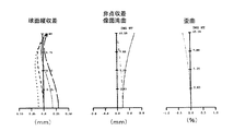
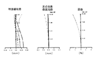
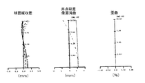
図2〜図4に、本発明のズームシステムの実施例に基づく収差特性のコンピュータによる計算結果の例を示した。各図において左から順に、球面縦収差(Longitudinal spherical aberration)、非点収差及び像面湾曲(Astigmatism 及び Field curves)、並びに歪曲(Distortion)のグラフを示した。図示の各曲線の意味については当業者には自明の事項であるので、ここでは説明は省略する。 FIGS. 2 to 4 show examples of calculation results of aberration characteristics by a computer based on an embodiment of the zoom system of the present invention. In each figure, graphs of longitudinal longitudinal aberration (Longitudinal spherical aberration), astigmatism and field curvature (Astigmatism and Field curves), and distortion (Distortion) are shown in order from the left. The meaning of each curve shown is self-evident to those skilled in the art, and a description thereof will be omitted.
1 ズームシステムの光軸
2 第1レンズ系
3 第2レンズ系
4 第3レンズ系
5 第4レンズ系
6 光線束
11 レンズ(材料A)
12 レンズ(材料B)
13 レンズ(材料C)
14 レンズ(材料D)
15 レンズ(材料D)
16 レンズ(材料C)
17 レンズ(材料B)
18 レンズ(材料A)
1’〜12’ 境界面
12 Lens (material B)
13 Lens (Material C)
14. Lens (Material D)
15 Lens (material D)
16 Lens (Material C)
17 Lens (Material B)
18 Lens (material A)
1'-12 'interface
Claims (5)
該ズームシステムの各レンズ(11〜18)は、次表に示す幾何学的構成、光学的特性及び互いに対する空気間隔を有すること
を特徴とするズームシステム:
A zoom system wherein each lens (11-18) of the zoom system has the geometrical configuration, optical properties and air spacing relative to each other as shown in the following table:
を特徴とする請求項1に記載のズームシステム:
|Pg,F−0.643−0.001628・νd|>0.006
及び/又は
|PC,t−0.5450−0.004743・νd|>0.008。 The zoom system according to claim 1, wherein the optical glass used satisfies the following standard linear relation for Abbe number ν d :
| P g, F −0.643−0.001628 · ν d |> 0.006
And / or | P C, t -0.5450-0.004743 · ν d |> 0.008.
を特徴とする請求項1又は2に記載のズームシステム。 The zoom system according to claim 1, wherein the curvature of field of the zoom system is adapted to the curvature of field of the eyepiece, depending on the choice of glass type and the structural characteristics.
を特徴とする請求項4に記載の顕微鏡。 The microscope according to claim 4, wherein the microscope is a stereo microscope having two channels.
Applications Claiming Priority (1)
| Application Number | Priority Date | Filing Date | Title |
|---|---|---|---|
| DE10249702A DE10249702A1 (en) | 2002-10-25 | 2002-10-25 | Optical zoom system for operation microscope using different glass types with 4 symmetrical lens groups having defined geometric and optical parameters |
Publications (2)
| Publication Number | Publication Date |
|---|---|
| JP2004145351A true JP2004145351A (en) | 2004-05-20 |
| JP4291667B2 JP4291667B2 (en) | 2009-07-08 |
Family
ID=32087175
Family Applications (1)
| Application Number | Title | Priority Date | Filing Date |
|---|---|---|---|
| JP2003366444A Expired - Fee Related JP4291667B2 (en) | 2002-10-25 | 2003-10-27 | Zoom system |
Country Status (4)
| Country | Link |
|---|---|
| US (1) | US6853494B2 (en) |
| EP (1) | EP1431796B1 (en) |
| JP (1) | JP4291667B2 (en) |
| DE (2) | DE10249702A1 (en) |
Families Citing this family (9)
| Publication number | Priority date | Publication date | Assignee | Title |
|---|---|---|---|---|
| DE202008017861U1 (en) * | 2008-03-11 | 2010-09-23 | Carl Zeiss Sports Optics Gmbh | Optical system |
| DE102008041819A1 (en) | 2008-09-04 | 2010-03-11 | Leica Microsystems (Schweiz) Ag | Optical imaging system |
| DE202009002387U1 (en) | 2008-12-22 | 2010-05-12 | Maiorova, Tatiana, Dmitrov | Optical arrangement for changing an imaging ratio or a refractive power |
| DE102008064512A1 (en) | 2008-12-22 | 2010-06-24 | Maiorova, Tatiana, Dmitrov | Optical arrangement for use in e.g. camera-phone for changing imaging condition and/or optical refraction power, has optical elements, where change of direction and/or vergrence is taken place in optical light path between elements |
| CN102109671B (en) * | 2009-12-25 | 2014-12-31 | 株式会社尼康 | Microscope device |
| DE102010044404A1 (en) | 2010-09-04 | 2012-03-08 | Leica Microsystems (Schweiz) Ag | Image sensor, video camera and microscope |
| CN102200638A (en) * | 2011-05-11 | 2011-09-28 | 长春理工大学 | Dichotomous optical design method of medium-wave infrared microscope objective |
| DE102014108811B3 (en) * | 2014-06-24 | 2015-11-26 | Carl Zeiss Meditec Ag | Stereo microscope with a main observer beam path and a co-observer beam path |
| CN111283320B (en) * | 2020-03-06 | 2022-02-15 | 深圳市大族数控科技股份有限公司 | Laser beam expanding lens and laser processing equipment |
Citations (1)
| Publication number | Priority date | Publication date | Assignee | Title |
|---|---|---|---|---|
| JPH11160625A (en) * | 1997-09-29 | 1999-06-18 | Carl Zeiss:Fa | Afocal zoom system |
Family Cites Families (6)
| Publication number | Priority date | Publication date | Assignee | Title |
|---|---|---|---|---|
| US3127466A (en) * | 1961-04-12 | 1964-03-31 | American Optical Corp | Variable magnification lens system for microscopes |
| US3731990A (en) * | 1971-10-28 | 1973-05-08 | Bausch & Lomb | Symmetrical copy lenses |
| JPS518932A (en) * | 1974-07-11 | 1976-01-24 | Minolta Camera Kk | 4 gun 4 maino shashinrenzu |
| JPS59211013A (en) * | 1983-05-16 | 1984-11-29 | Fuji Photo Optical Co Ltd | Plastic objective lens system subjected to temperature compensation |
| DE59500569D1 (en) * | 1995-06-03 | 1997-10-02 | Schneider Co Optische Werke | Telecentric measuring lens on both sides |
| JP3567316B2 (en) * | 1995-10-06 | 2004-09-22 | 富士写真光機株式会社 | Zoom lens system at finite conjugate distance |
-
2002
- 2002-10-25 DE DE10249702A patent/DE10249702A1/en not_active Withdrawn
-
2003
- 2003-10-22 DE DE50302653T patent/DE50302653D1/en not_active Expired - Lifetime
- 2003-10-22 EP EP03024243A patent/EP1431796B1/en not_active Expired - Lifetime
- 2003-10-24 US US10/692,571 patent/US6853494B2/en not_active Expired - Fee Related
- 2003-10-27 JP JP2003366444A patent/JP4291667B2/en not_active Expired - Fee Related
Patent Citations (1)
| Publication number | Priority date | Publication date | Assignee | Title |
|---|---|---|---|---|
| JPH11160625A (en) * | 1997-09-29 | 1999-06-18 | Carl Zeiss:Fa | Afocal zoom system |
Also Published As
| Publication number | Publication date |
|---|---|
| DE10249702A1 (en) | 2004-05-06 |
| US6853494B2 (en) | 2005-02-08 |
| EP1431796A2 (en) | 2004-06-23 |
| JP4291667B2 (en) | 2009-07-08 |
| DE50302653D1 (en) | 2006-05-11 |
| EP1431796B1 (en) | 2006-03-15 |
| EP1431796A3 (en) | 2005-01-19 |
| US20040114223A1 (en) | 2004-06-17 |
Similar Documents
| Publication | Publication Date | Title |
|---|---|---|
| KR102044240B1 (en) | Zoom lens system and electronic imaging apparatus using the same | |
| JPH11160625A (en) | Afocal zoom system | |
| JP4528497B2 (en) | Objective lens for telescopic stereo microscope | |
| US6104541A (en) | Collimator lens and optical scanning apparatus using the same | |
| JP2003015047A (en) | Immersion system microscope objective | |
| US10948704B2 (en) | Objective for a confocal microscope | |
| JP4291667B2 (en) | Zoom system | |
| EP2362260B1 (en) | Variable power optical system for stereo microscope | |
| WO2009011441A1 (en) | Scanning type confocal microscope | |
| US6822805B2 (en) | Objective lens | |
| US5946141A (en) | Apochromatic lens system for relaying laser beam waists | |
| US7643216B2 (en) | Microscope objective | |
| US7561339B2 (en) | Objective for stereomicroscopes | |
| JPH046512A (en) | Objective lens for microscope | |
| KR20030025828A (en) | Projection lens and projector provided with the same | |
| CN109983383B (en) | Endoscope objective optical system | |
| JP3861372B2 (en) | microscope | |
| JPWO2019131748A1 (en) | Lens system and imaging device | |
| US20060285219A1 (en) | Tube lens unit with chromatically compensating effect | |
| JP7079895B2 (en) | Endoscope objective optical system and endoscope | |
| JP2017111423A (en) | Zoom objective lens | |
| US7492531B2 (en) | Apochromatic condenser | |
| WO2020021662A1 (en) | Microscope objective lens and microscope | |
| US20030133198A1 (en) | Objective lens | |
| JP2020517992A (en) | Corrective objective lens for microscope |
Legal Events
| Date | Code | Title | Description |
|---|---|---|---|
| A621 | Written request for application examination |
Free format text: JAPANESE INTERMEDIATE CODE: A621 Effective date: 20060413 |
|
| TRDD | Decision of grant or rejection written | ||
| A01 | Written decision to grant a patent or to grant a registration (utility model) |
Free format text: JAPANESE INTERMEDIATE CODE: A01 Effective date: 20090331 |
|
| A01 | Written decision to grant a patent or to grant a registration (utility model) |
Free format text: JAPANESE INTERMEDIATE CODE: A01 |
|
| A61 | First payment of annual fees (during grant procedure) |
Free format text: JAPANESE INTERMEDIATE CODE: A61 Effective date: 20090403 |
|
| R150 | Certificate of patent or registration of utility model |
Free format text: JAPANESE INTERMEDIATE CODE: R150 |
|
| FPAY | Renewal fee payment (event date is renewal date of database) |
Free format text: PAYMENT UNTIL: 20120410 Year of fee payment: 3 |
|
| S111 | Request for change of ownership or part of ownership |
Free format text: JAPANESE INTERMEDIATE CODE: R313113 |
|
| FPAY | Renewal fee payment (event date is renewal date of database) |
Free format text: PAYMENT UNTIL: 20120410 Year of fee payment: 3 |
|
| R350 | Written notification of registration of transfer |
Free format text: JAPANESE INTERMEDIATE CODE: R350 |
|
| FPAY | Renewal fee payment (event date is renewal date of database) |
Free format text: PAYMENT UNTIL: 20130410 Year of fee payment: 4 |
|
| FPAY | Renewal fee payment (event date is renewal date of database) |
Free format text: PAYMENT UNTIL: 20140410 Year of fee payment: 5 |
|
| R250 | Receipt of annual fees |
Free format text: JAPANESE INTERMEDIATE CODE: R250 |
|
| R250 | Receipt of annual fees |
Free format text: JAPANESE INTERMEDIATE CODE: R250 |
|
| LAPS | Cancellation because of no payment of annual fees |