JP4222664B2 - Epi-illumination microscope - Google Patents
Epi-illumination microscope Download PDFInfo
- Publication number
- JP4222664B2 JP4222664B2 JP30223798A JP30223798A JP4222664B2 JP 4222664 B2 JP4222664 B2 JP 4222664B2 JP 30223798 A JP30223798 A JP 30223798A JP 30223798 A JP30223798 A JP 30223798A JP 4222664 B2 JP4222664 B2 JP 4222664B2
- Authority
- JP
- Japan
- Prior art keywords
- epi
- optical system
- optical path
- illumination
- observation
- Prior art date
- Legal status (The legal status is an assumption and is not a legal conclusion. Google has not performed a legal analysis and makes no representation as to the accuracy of the status listed.)
- Expired - Fee Related
Links
- 238000005286 illumination Methods 0.000 title claims description 79
- 230000003287 optical effect Effects 0.000 claims description 254
- 230000001678 irradiating effect Effects 0.000 claims description 11
- 238000000926 separation method Methods 0.000 claims description 2
- 230000005284 excitation Effects 0.000 description 43
- QSHDDOUJBYECFT-UHFFFAOYSA-N mercury Chemical compound [Hg] QSHDDOUJBYECFT-UHFFFAOYSA-N 0.000 description 27
- 229910052753 mercury Inorganic materials 0.000 description 27
- 239000003153 chemical reaction reagent Substances 0.000 description 24
- 230000004888 barrier function Effects 0.000 description 17
- 238000003384 imaging method Methods 0.000 description 15
- 230000003595 spectral effect Effects 0.000 description 15
- 238000002834 transmittance Methods 0.000 description 15
- 238000010586 diagram Methods 0.000 description 13
- 238000000034 method Methods 0.000 description 13
- 238000003780 insertion Methods 0.000 description 9
- 230000037431 insertion Effects 0.000 description 9
- 230000000694 effects Effects 0.000 description 7
- 238000002474 experimental method Methods 0.000 description 7
- 238000000651 laser trapping Methods 0.000 description 5
- 239000000126 substance Substances 0.000 description 5
- 238000005259 measurement Methods 0.000 description 4
- 102000004169 proteins and genes Human genes 0.000 description 4
- 108090000623 proteins and genes Proteins 0.000 description 4
- 230000036978 cell physiology Effects 0.000 description 3
- 230000003834 intracellular effect Effects 0.000 description 3
- 230000015572 biosynthetic process Effects 0.000 description 1
- 230000006866 deterioration Effects 0.000 description 1
- 238000000605 extraction Methods 0.000 description 1
- 238000012576 optical tweezer Methods 0.000 description 1
- 238000005375 photometry Methods 0.000 description 1
- 238000004611 spectroscopical analysis Methods 0.000 description 1
Images


Landscapes
- Microscoopes, Condenser (AREA)
- Lenses (AREA)
Description
【0001】
【発明の属する技術分野】
本発明は落射蛍光顕微鏡に係り、特に、細胞生理学分野において細胞操作の手段として用いられるレーザートラップ法やCaged試薬解除法を採用した落射蛍光顕微鏡に関する。
【0002】
【従来の技術】
落射蛍光顕微鏡による落射蛍光観察は、生物学の分野において、細胞内部の特定の物質の形態観察を行う為の手段として、現在広く一般的に行われている方法である。
【0003】
ところで、最近、特に細胞生理学の分野においては、顕微鏡の落射照明手段を利用した細胞内部物質の操作方法として、レーザートラップ法やCaged試薬解除法が広く採用されている。
【0004】
ここで、レーザートラップ法(光ピンセット法)は、標本中の任意の物質にレーザー光を照射して光学的に捕捉する方法であり、細胞内のタンパク質が運動する際の力量を測定する手段として用いられ、照射手段としては、赤外レーザーが使用される。一方、Caged試薬解除法は、生理活性を持つ分子にCaged試薬を結合して活性を抑制した状態で細胞内に投与し、光を照射することで結合を解除させてその分子の活性を回復させる方法であり、照射手段としては、紫外光が使用される。
【0005】
このように、これらレーザートラップ法やCaged試薬解除法を採用する落射蛍光顕微鏡では、通常の落射蛍光照明の他に、細胞操作のための各種の光源が必要になってくる。
【0006】
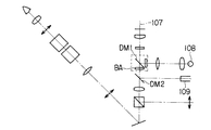
しかして、従来、一般的に用いられている落射蛍光顕微鏡として、図12に示すように対物レンズ101と接眼レンズ102を結ぶ観察光学系光路103中にバリアフィルターBAとともに配置される第1ダイクロイックミラーDM1に対して蛍光観察用の励起光源104を配置するとともに、これら第1ダイクロイックミラーDM1と励起光源104の間に第2ダイクロイックミラーDM2を配し、この第2ダイクロイックミラーDM2と励起光源104の間にバンドパスフィルタBPを配置し、第2ダイクロイックミラーDM2から直交する光路上に標本操作用光源105を配置したものがある。
【0007】
また、特開平8−234110号公報には、落射蛍光顕微鏡として、図13に示すように、観察光学系光路107に蛍光観察用の励起光源108から励起光を導入する第1ダイクロイックミラーDM1と、レーザー光源109からレーザートラップのレーザー光を導入する第2ダイクロイックミラーDM2を2段に配置したものが開示されている。
【0008】
【発明が解決しようとする課題】
ところが、図12に示した従来のものは、励起光源104を、励起波長を切換えて蛍光観察を行うことを考えると、バンドパスフィルタBPは勿論のこと、第1ダイクロイックミラーDM1をも交換しなければならないが、このとき、第1ダイクロイックミラーDM1とバンドパスフィルタBPは、別々に配置されているので、これらを各別に交換しなければならず、このための作業が煩雑で面倒になるという問題がある。
【0009】
一方、特開平08−234110号公報に開示されているものは、第1ダイクロイックミラーDM1が、第2ダイクロイックミラーDM2よりも標本側に配置される場合、例えば、レーザー光源109のレーザー波長域を紫外域に切換えてCaged試薬解除用として使用すると、第2ダイクロイックミラーDM2を反射したレーザー光を確実に標本側に導入するためには、第1ダイクロイックミラーDM1およびバリアフィルタBAとして、レーザー光源109からのレーザー波長を透過する特性を有していなければならず、その度に第1ダイクロイックミラーDM1およびバリアフィルタBAを最適なものに取り替えるなどの面倒な作業が必要となり、実現性がうすい。現実的に見てレーザー光源109は、レーザートラップ用の赤外領域以外の使用目的には対応できず、汎用性に乏しい。また、第2ダイクロイックミラーDM2は観察光学系光路107の中に固定されているので、通常の蛍光観察においては問題はないが、1分子レベルの測光を行うような微弱蛍光観察においては光量ロスの要因となり好ましくない。
【0010】
本発明は上記事情に鑑みてなされたものであり、落射照明光学系の独立した光路を複数有し、各々の落射照明光路の用途が限定されない、汎用性に富んだ落射蛍光顕微鏡を提供することを目的とする。
【0011】
【課題を解決するための手段】
本発明の一観点によれば、複数の落射照明光を選択的に標本に照射することにより、標本の光学的操作と蛍光観察を同時に可能にした落射蛍光顕微鏡において、前記標本に対する観察光学系光路に交点を介して交差する方向に配置された第1の落射照明光学系光路と、前記観察光学系光路の前記第1の落射照明光学系光路と同一の交点で前記観察光学系光路と交差する方向に配置された第2の落射照明光学系光路と、前記観察光学系光路に、前記第1および第2の落射照明光学系光路と異なる交点を介して交差する方向に配置された第3の落射照明光学系光路とにより構成している。
【0012】
これにより、例えば第1の落射照明光学系光路にCaged試薬解除用のレーザー光源、第2の落射照明光学系光路に励起光照射用の水銀ランプを、さらに第3の落射照明光学系光路にレーザートラップ用のレーザー光源または励起光照射用の水銀ランプをそれぞれ配して、これら第1乃至第3の落射照明光学系光路を選択し、Caged試薬解除用のレーザー光源、励起光照射用の水銀ランプおよびレーザートラップ用のレーザー光源を組み合わせることにより、Caged解除と蛍光観察によるCaged試薬解除実験や蛍光観察とレーザートラップによる微小物体の捕捉および微小力計測などのレーザートラップ実験を選択的に行うことができる。
【0013】
前記落射蛍光顕微鏡において、前記観察光学系光路と前記第3落射照明光学系光路との交点に、波長分別手段を挿脱可能に配置していることが望ましい。
【0014】
これにより、レーザートラップを行わず通常の蛍光観察のみを行う場合、例えば、ダイクロックミラーなどの波長分別手段を観察光路から除外することにより、微弱蛍光観察時の光量ロスを除外した観察像を得ることができる。また、波長分別手段を観察光路に挿入することにより、例えば第3の落射照明光学系光路に配したレーザートラップ用のレーザー光源または励起光照射用の水銀ランプによるレーザートラップ用レーザーと蛍光観察用の励起光を選択的に観察光学系光路に導入できるので、この場合も、必要に応じてレーザートラップ実験やCaged試薬解除実験を選択的に行うことができ、汎用性に富んだ実験系を構成することができる。
【0015】
前記落射蛍光顕微鏡において、前記観察光学系光路に、さらに前記第1および第2の落射照明光学系光路および前記第3落射照明光学系光路と異なる交点を介して交差する方向に第4の落射照明光学系光路を配置してもよい。
【0016】
これにより、例えば第1の落射照明光学系光路に励起光照射用のレーザー光源、第2の落射照明光学系光路に励起光照射用の水銀ランプを、さらに第3の落射照明光学系光路にレーザートラップ用のレーザー光源を配し、さらに、第4の落射照明光学系光路にCaged試薬解除用のレーザー光源を配し、第1乃至第2の落射照明光学系光路を選択し、励起光源の水銀ランプおよびレーザー光源を選択的に使用し、レーザートラップ用のレーザーとCaged試薬解除用のレーザーを使用することで、細胞内の任意のタンパク質に紫外レーザーを照射してCaged試薬を解除し、活性化したタンパク質に赤外レーザーを照射してトラップし、微小計測を行うような操作が可能となり、細胞内物質の挙動を分子レベルで解析する細胞生理学の分野において非常に有効な実験系を構築することが可能となる。
【0017】
【発明の実施の形態】
以下、本発明の実施の形態を図面に従い説明する。
【0018】
(第1の実施の形態)
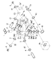
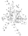
図1および図2は、本発明が適用される倒立型の落射蛍光顕微鏡の概略構成を示している。図において、1は観察すべき標本で、この標本1の下方に対物レンズ2を配置し、この対物レンズ2を通る観察光学系光路の光軸31上に破線で示すキューブターレットCTを設けている。
【0019】
このキューブターレットCTは、光軸31に対して45°の斜度を持つダイクロイックミラーDM1を有するキューブCV1と、光軸31に対して45°の斜度を持つダイクロイックミラーDM1′、バリアフィルタBA1′および励起フィルタEX1′を有するキューブCV1′を備えていて、光軸31に対して垂直平面内を図示しない回転軸を中心に回転することにより、キューブCV1またはキューブCV1′を選択的に光軸31の交わる点O1に位置合わせさせるようにしている。
【0020】
なお、図1に示すキューブターレットCTは、2つのキューブしか表示されていないが、キューブCV1,CV1′と同一構成、同一形状のキューブを少なくとも4つ挿脱することができ、ターレットの回転と図示しない位置決め機構により、任意のキューブのダイクロイックミラーの反射面を光軸31の交わる点O1に合わせることができる。例えば、図2では、キューブターレット内部CTにダイクロイックミラーDM1″、バリアフィルタBA1″を有するキューブCV1″を挿入した例を示しており、後述するレーザー光源3および水銀光源6の波長を変えた場合に適用できるようにしている。また、キューブCV1′は、光軸31に挿入された時にダイクロイックミラーDM1′の反射面が後述する水銀光源6の方に向くようにダイクロイックミラーDM1′を保持している。
【0021】
そして、キューブターレットCTの点O1から光軸31に対して垂直方向の第1の落射照明光学系光路の光軸32上にリレーレンズ5、コレクタレンズ4およびレーザー光源3を同一直線上に配置し、また、点O1から光軸31に対して垂直で、さらに点O1からレーザー光源3への方向に対して垂直方向の第2の落射照明光学系光路の光軸33上にリレーレンズ8、コレクタレンズ7および水銀光源6を同一直線上に配置している。
【0022】
キューブターレットCTの下方には、破線で示すスライダーSVを後述する光軸34に沿って移動可能に設けている。
【0023】
このスライダーSVは、光軸32に対して45°の斜度を持つダイクロイックミラーDM2、バリアフィルタBA2および励起フィルタEX2を有するキューブCV2と、このダイクロイックミラーDM2と平行に配置したダイクロイックミラーDM2′を有するキューブCV2′を、ダイクロイックミラーDM2により光軸32が反射される方向(光軸34の方向)に並べて設けている。これらキューブCV2とCV2′は、スライダーSVに挿脱可能になっている。また、スライダーSVのキューブCV2の真下には、結像レンズ15を配置し、キューブCV2′の真下には、結像レンズ16を配置している。
【0024】
そして、スライダーSVを光軸34方向に沿って移動することで、キューブCV2のダイクロイックミラーDM2の反射面またはキューブCV2′のダイクロイックミラーDM2′の反射面を選択的に光軸31と交わる点O2に位置合わせさせるようにしている。
【0025】
なお、スライダーSV上のダイクロイックミラーDM2,DM2′の切り換え停止位置は、図示しない位置決め機構により設定される。
【0026】
そして、スライダーSVの点O2から反射された第3の落射照明光学系光路の光軸34上には、リレーレンズ11、コレクタレンズ10および水銀光源9を配置している。また、リレーレンズ11とコレクタレンズ10の間の光軸34上には、光軸34と交わる点O3に、スライダーSV′を挿脱可能に配置し、このスライダーSV′を介して光軸34に対し垂直方向にコレクタレンズ13およびレーザー光源12を配置している。
【0027】
この場合、スライダーSV′には、全反射ミラー14を設けており、スライダーSV′の図中矢印方向への移動により、全反射ミラー14の反射面を点O3に挿脱し、レーザー光源12からの光束を光軸31と交わる点O2方向へ導くことができるようにしている。なお、スライダーSV′の挿脱位置は、図示しない位置決め機構により自動的に設定される。
【0028】
一方、スライダーSV下方の光軸31上には、光路分割のためのハーフプリズム17、光軸31を接眼部へと導く全反射ミラー18を配置している。
【0029】
結像レンズ15又は16を透過した観察光は、ビームスプリッタ17によって2分割される。ビームスプリッタ17で反射した光は撮影光路に導かれ、写真撮影装置又はTVカメラの受光面Ph上で結像する。
【0030】
また、ビームスプリッタ17を透過した光は全反射ミラー18で反射され、観察光路に導かれる。観察光路上の中間結像点Aでいったん結像した後、リレーレンズR1でリレーされて点Bで再び結像し、この像が接眼レンズOcによって観察される。
【0031】
次に、このように構成した実施の形態の動作を説明する。
【0032】
いま、レーザー光源3にCaged試薬解除用の波長337nmのN2 レーザーを使用し、水銀光源6に励起光照射用で蛍光観察用の波長488nmの光を取り出すための水銀光を使用し、水銀光源9に励起光照射用で蛍光観察用の波長532nmの光を取り出すための水銀光を使用し、レーザー光源12にレーザートラップ用の波長1064nmのIRレーザーを使用するものとする。
【0033】
まず、図1に示すように、キューブターレットCTのキューブCV1を光軸31上に位置させるとともに、スライダーSVのキューブCV2を観察光学系光路の光軸31に挿入し、スライダーSV′を光軸34から取り外す。
【0034】
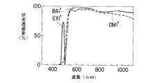
この状態で、レーザー光源3の波長337nmのCaged試薬解除用のN2 レーザーが、コレクタレンズ4、リレーレンズ5を介してキューブCV1のダイクロイックミラーDM1に入射される。ここで、ダイクロイックミラーDM1に波長が400nm以下の光を反射し、400nmを超える光を透過する図3に示す分光透過率特性を有するものが用いられると、レーザー光源3のN2 レーザーは、ダイクロイックミラーDM1で反射し、対物レンズ2を通して標本1の観察視野内の所定位置に照射され、Caged試薬解除が行われる。
【0035】
一方、この状態では、スライダーSVのキューブCV2のダイクロイックミラーDM2が光軸31と交わる点O2に位置され、スライダーSV′が光軸34から外れているので、水銀光源9の波長532nmの水銀光が、コレクタレンズ10、リレーレンズ11を介して、ダイクロイックミラーDM2′に入射される。ここで、ダイクロイックミラーDM2′に波長が800nm以下の光を透過し800nmを超える光を反射する図4に示す分光透過率特性を有するものが用いられると、水銀光源9からの光は、ダイクロイックミラーDM2′を透過し、キューブCV2の励起フィルタEX2に入射され、さらに、この励起フィルタEX2に励起光波長510nm以上550nm以下の光を透過する図5に示す分光透過率特性を有するものが用いられると、励起光のみが透過し、ダイクロイックミラーDM2に入射される。さらに、ダイクロイックミラーDM2に、波長が570nm以下の光を反射し、570nmを超える光を透過する図5に示す分光透過率特性を有するものが用いられると、励起フィルタEX2からの励起光は、ダイクロイックミラーDM2で上方に反射し、ダイクロイックミラーDM1を透過して対物レンズ2を介して標本1の観察視野に照射される。
【0036】
そして、励起光の照射により、標本1から蛍光が発すると、この蛍光は、対物レンズ2を通り、ダイクロイックミラーDM1、DM2を介してキューブCV2のバリアフィルタBA2に入射される。ここで、バリアフィルタBA2に、波長590nm以下の光を反射し、590nmを超える光を透過する図5に示す分光透過率特性を有するものが用いられると、蛍光は、透過して、ハーフプリズム17、全反射ミラー18を通して蛍光観察が行なわれる。
【0037】
これにより、Caged試薬解除及び蛍光観察を同時に行なうことができる。
【0038】
ここで、Caged試薬解除及び蛍光観察を同時に行なう際に使用されるダイクロイックミラーDM1,DM2の特性に関してまとめると次のようになる。
【0039】
すなわち、ダイクロイックミラーDM1としては、レーザー光源3からのレーザー光(波長が400nm以下)を反射する一方、水銀光源9からの励起光や標本1から発せられる光(波長が400nm超)を透過するものが使用される(図3参照)。また、ダイクロイックミラーDM2としては、水銀光源9からの励起光(波長が570nm以下)を反射する一方、標本1から発せられる光(波長が570nm超)を透過するものが使用される(図5参照)。
【0040】
次に、図2に示すように、キューブターレットCTを図示矢印方向に回転して、キューブCV1′を光軸31上に位置させ、また、スライダーSVの切り換えにより、キューブCV2′を光軸31に挿入し、さらに、スライダーSV′を切り換えて全反射ミラー14を光軸34に挿入する。
【0041】
この状態で、水銀光源6の蛍光観察用の波長488nmの水銀光が、コレクタレンズ7、リレーレンズ8を介してキューブCV1′の励起フィルタEX1′に入射される。ここで、励起フィルタEX1′に波長が470nm以上490nm以下の光を透過する図6に示す分光透過率特性を有するものが用いられると、励起光のみがダイクロイックミラーDM1′に入射され、さらに、ダイクロイックミラーDM1′として波長が500nm以下の光を反射し500nmを超える光を透過する図6に示す分光透過率特性を有するものが用いられると、励起フィルタEX1′の励起光は、ダイクロイックミラーDM1′で上方に反射し、対物レンズ2を介して標本1の観察視野に照射される。
【0042】
そして、励起光の照射により標本1から蛍光が発すると、この蛍光は、対物レンズ2を通りダイクロイックミラーDM1′を透過して、キューブCV1′のバリアフィルタBA1′に入射される。ここで、バリアフィルタBA1′に波長515nm以下の光を反射し、515nmを超える光を透過する図6に示す分光透過率特性を有するものが用いられると、蛍光は、透過して、スライダーSVのダイクロイックミラーDM2′に入射される。この時の蛍光の波長は800nm以下なので、ダイクロイックミラーDM2′を透過し、ハーフプリズム17、全反射ミラー18を通して蛍光観察が行なわれる。
【0043】
一方、スライダーSV′が光軸34上に挿入されていることで、レーザー光源12にレーザートラップ用の波長1064nmのIRレーザーが、コレクタレンズ13を通って全反射ミラー14に入射し、ここで全反射され、キューブCV2′のダイクロイックミラーDM2′に入射される。すると、ダイクロイックミラーDM2′の分光透過率特性により上方に反射し、キューブCV1′のバリアフィルタBA1′に入射されるが、このバリアフィルタBA1′の分光透過率特性により透過し、さらに、ダイクロイックミラーDM1′の分光透過率特性により透過し、対物レンズ2に入射される。
【0044】
すると、対物レンズ2に入射されたレーザー光は、集光され、標本1上の所定位置にレーザースポットとして照射され、この照射されたレーザー集光点の近傍において、標本1中の微小物体を光学的に捕捉することができる。
【0045】
これにより、蛍光観察及びレーザートラップによる微小物体の捕捉・微小力計測等を同時に行なうことができる。
【0046】
ここで、蛍光観察及びレーザートラップによる微小物体の捕捉・微小力計測等を同時に行なう際に使用されるダイクロイックミラーDM1′,DM2′の特性に関してまとめると次のようになる。
【0047】
すなわち、ダイクロイックミラーDM1′としては、水銀光源6からの励起光(波長が500nm以下)を反射する一方、レーザー光源12から送られてくるレーザー光や標本1から発せられる光(波長が500nm超)を透過するものが使用される(図6参照)。また、ダイクロイックミラーDM2′としては、レーザー光源12からのレーザー光(波長が800nm以下)を反射する一方、標本1から発せられる光(波長が800nm超)を透過するものが使用される(図4参照)。
【0048】
従って、このような構成とすれば、第1の落射照明光学系光路のCaged試薬解除用のレーザー光源3からのレーザー光をキューブCV1のダイクロイックミラーDM1を介して標本1側に導入し、同時に、第3の落射照明光学系光路の励起光照射用の水銀ランプ9からの励起光をキューブCV2′のダイクロイックミラーDM2′およびキューブCV2のダイクロイックミラーDM2を介して標本1側に導入することにより、Caged試薬解除及び蛍光観察によるCaged試薬解除実験を行うことができ、一方、第2の落射照明光学系光路の励起光照射用の水銀ランプ6からの励起光をキューブCV1′のダイクロイックミラーDM1′を介して標本1側に導入し、同時に、第3の落射照明光学系光路のレーザートラップ用のレーザー光源12からのレーザー光をキューブCV2′のダイクロイックミラーDM2′を介して標本1側に導入することにより蛍光観察及びレーザートラップによる微小物体の捕捉・微小力計測などのレーザートラップ実験を選択的に行うことができるようになり、標本操作をともない、これら2種類の実験が選択的に可能で、汎用性のある落射蛍光顕微鏡が提供できる。
【0049】
なお、この第1の実施の形態では、倒立型顕微鏡について述べたが、一般の正立型顕微鏡にも適用することができる。また、今回用いた光源の種類、波長、数、配置については必ずしも同一でなくてもよい。また、各照明光学系光路と観察光学系光路(光軸31)との交差角度は、90°である必要はなく、また、互いに異なった角度であってもよい。さらに、今回用いたダイクロイックミラーの特性は必ずしも同一でなくてもよく、所望の光束の波長特性に適したものであれば、ダイクロイックプリズムや他の適当な波長分別手段を適用してもよい。また、ダイクロイックミラーの光軸への挿脱機構は、キューブターレットCTおよびスライダーSVと同一でなくてもよく、他のどのような挿脱機構であってもよい。そして結像レンズ15,16をスライダーSVに取り付けずに、どちらか一方を顕微鏡本体の光軸上の所定位置に固定するようにしてもよい。
【0050】
(第2の実施の形態)
図7は、本発明の第2の実施の形態の概略構成を示すもので、図1と同一部分には、同符号を付している。
【0051】
この場合、図7は、図1の構成からレーザー光源12、コレクタレンズ13、全反射ミラー14、スライダーSV′、ダイクロイックミラーDM2′、キューブCV2′を除去したもので、その他は、図1と同様である。
【0052】
このように構成した第2の実施の形態は、端的に言えば図1の構成からレーザー光源12を取り外し、キューブCV2′を外したものである。
【0053】
このため、スライダーSV′を切り換えて結像レンズ16を光軸31に挿入し、また、キューブターレットCTのターレットを回転し、キューブの入っていない部分を光軸31の位置に合わせるか、もしくは、キューブCV1を外すことによって観察光学系の平行光束光路中(対物レンズ2から結像レンズ16の間)に余分な光学素子の入らない状態を作り出せば、簡易的な操作のみで通常の倒立型顕微鏡に切り換えることができる。
【0054】
このようにすれば、単一の励起光のみを標本に照射する通常の蛍光観察では使用しないダイクロイックミラーやバリアフィルタを観察光路から取り除くことにより、使われないキューブが観察光路に入っているが故に、ある範囲の波長帯の蛍光は観察光路から反射され、除去されてしまうような予期せぬ不具合を未然に防ぐことができる。また、余分な光学素子を除去することで、微弱蛍光観察時の光量ロスを未然に防ぎ、その他蛍光観察と他の検鏡法とを組み合わせた観察像の劣化も防ぐことが出来る。
【0055】
なお、図7に示す構成で、レーザートラップを使用したい場合には、図7のスライダーSVのキューブCV2を、図8に示すようにキューブCV2′に変更し、また、水銀光源9に代えてレーザー光源12を用いればよい。
【0056】
このような構成にすれば、レーザートラップ及び蛍光観察が同時に行えるとともに、上述したと同様な効果を期待することができる。また、このような実施の形態においては、使用したい光源に合わせてスライダーSVに取り付けるキューブを他のものに変えてもよい。
【0057】
なお、この第2の実施の形態では、倒立型顕微鏡について述べたが、一般の正立型顕微鏡にも適用することができる。また、今回用いた光源の種類、波長、数、配置については必ずしも同一でなくてもよい。また、各照明光学系光路と観察光学系光路(光軸31)との交差角度は、90°である必要はなく、また、互いに異なった角度であってもよい。さらに、今回用いたダイクロイックミラーの特性は必ずしも同一でなくてもよく、所望の光束の波長特性に適したものであれば、ダイクロイックプリズムや他の適当な波長分別手段を適用してもよい。また、ダイクロイックミラーの光軸への挿脱機構は、キューブターレットCTおよびスライダーSVと同一でなくてもよく、他のどのような挿脱機構であってもよい。そして結像レンズ15,16をスライダーSVに取り付けずに、どちらか一方を顕微鏡本体の光軸上の所定位置に固定するようにしてもよい。
【0058】
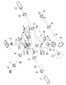
(第3の実施の形態)
図9は、本発明の第3の実施の形態の概略構成を示すもので、図1と同一部分には、同符号を付している。
【0059】
この場合、図9は、図1に示すスライダーSVに代え、スライダーSVを延長して結像レンズ19を新たに加えたスライダーSV″を設けたもので、その他は、図1と同様である。
【0060】
このように構成した第3の実施の形態は、スライダーSV″を切り換えることにより、図示しない位置決め機構によりキューブCV2,CV2′および結像レンズ19を観察光学系の平行光束光路中に挿入することができる。
【0061】
このようにすれば、第1の実施の形態で述べた効果を何ら損なうことなく、さらに第2の実施の形態で述べた効果を得ることができる。すなわち、簡単に述べると簡易的切り換えのみで、様々な光束の選択的使用が可能で、通常の倒立型顕微鏡としての使用も可能な倒立型顕微鏡を提供できる。
【0062】
また、この第3の実施の形態では、倒立型顕微鏡について述べたが、一般の正立型顕微鏡にも適用することができる。また、今回用いた光源の種類、波長、数、配置については必ずしも同一でなくてもよい。また、各照明光学系光路と観察光学系光路(光軸31)との交差角度は、90°である必要はなく、また、互いに異なった角度であってもよい。さらに、今回用いたダイクロイックミラーの特性は必ずしも同一でなくてもよく、所望の光束の波長特性に適したものであれば、ダイクロイックプリズムや他の適当な波長分別手段を適用してもよい。また、ダイクロイックミラーの光軸への挿脱機構は、キューブターレットCTおよびスライダーSV″と同一でなくてもよく、他のどのような挿脱機構であってもよい。そして結像レンズ15,16,19はスライダーSV″に取り付けられている必要はなく、例えば、結像レンズ15,16,19のうち、いずれか一つを顕微鏡本体の光軸上に固定し、他の2つを除外しても良い。
【0063】
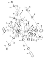
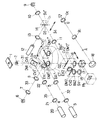
(第4の実施の形態)
図10は、本発明の第4の実施の形態の概略構成を示すもので、図2と同一部分には、同符号を付している。
【0064】
この場合、図10は、図2の構成の対物レンズ2と点O1との間の観察光学系光路の光軸31上に点O4を設け、この点O4が光軸の反射点となるようにダイクロイックミラーDM1を有するキューブCV1を配置し、このダイクロイックミラーDM1により反射された第4の落射照明光学系光路の光軸35上にリレーレンズ22、コレクタレンズ21、レーザー光源20を同一直線上に配置している。その他は、図2と同様である。
【0065】
このように構成した第4の実施の形態では、レーザー光源20として、Caged試薬解除用の波長337nmのN2 レーザー光源を用いると、レーザー光源20より発振されたレーザー光は、コレクタレンズ21、リレーレンズ22を通って、上述したダイクロイックミラーDM1の特性により上方に反射され、標本1の観察視野内の所定位置を照射する。
【0066】
つまり、このようにすることで、蛍光観察、レーザートラップ使用時にCaged試薬解除を追加できるようにし、第1の実施の形態で説明した各光学素子の波長特性を利用して3つの光源を同時に使用することができる。
【0067】
これにより、励起光を照射し、細胞内部の蛍光観察を行いながら、細胞内の任意のタンパク質にN2 レーザーを照射して、Caged試薬を解除し、活性化したタンパク質にIRレーザーを照射して光学的に捕捉し、微小力計測を行なうようなことが可能になり、細胞内物質の挙動を分子レベルで解析する細胞生理学の分野において非常に有効である。つまり、このように専門分野の探求においては、様々な光源を同時にいくつも使用したいことが多々あるが、図10のような構成をとることにより、上述した学問的メリットの大きい装置を提供することができる。
【0068】
なお、第4の実施の形態ではレーザートラップ用のダイクロイックミラーDM2′は、その他の光軸上のダイクロイックミラーの中で一番下に配置されているが、どの位置に配置されていてもよい。また、光軸上のダイクロイックミラーは追加してもよい。キューブCV1は、単独で存在するが、なんらかの機構を用いてキューブCV1の位置に複数のキューブが挿脱できるようにしてもよい。
【0069】
また、この第4の実施の形態では、倒立型顕微鏡について述べたが、一般の正立型顕微鏡にも適用することができる。また、今回用いた光源の種類、波長、数、配置については必ずしも同一でなくてもよい。また、各照明光学系光路と観察光学系光路(光軸31)との交差角度は、90°である必要はなく、また、互いに異なった角度であってもよい。さらに、今回用いたダイクロイックミラーの特性は必ずしも同一でなくてもよく、所望の光束の波長特性に適したものであれば、ダイクロイックプリズムや他の適当な波長分別手段を適用してもよい。また、ダイクロイックミラーの光軸への挿脱機構は、キューブターレットCTおよびスライダーSVと同一でなくてもよく、他のどのような挿脱機構であってもよい。そして結像レンズ15,16をスライダーSVに取り付けずに、どちらか一方を顕微鏡本体の光軸上の所定位置に固定するようにしてもよい。
【0070】
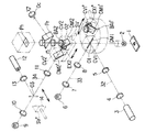
(第5の実施の形態)
前述した各実施の形態が正立型顕微鏡にも適用可能である旨は既に述べた通りである。そこで、本発明をその正立型顕微鏡で構成した場合の一実施形態を図11を参照して説明する。
【0071】
図11は、本発明を正立型顕微鏡で構成した実施の形態の概略構成を示している。図において、1は観察すべき標本であり、この標本の上方に、対物レンズをはじめとする落射照明および観察光学系が配置されている。
【0072】
ここに示した結像レンズ15より対物レンズ側にある落射照明光学系の構成要素に付した記号は、図1において示した構成要素の記号に対応して同一の構成要素であることを示している。すなわち、第1の実施の形態で示した図1の倒立型顕微鏡における落射照明光学系をおおよそ反転した態様で構成されている。
【0073】
結像レンズ15の上方には光路分割プリズムPrが配置され、この光路分割プリズムPrを透過した観察光は、写真装置やTVカメラ等の撮像面Ph上で結像される。一方、光路分割プリズムPrを反射した観察光は、接眼レンズOcの手前で結像され、接眼レンズOcを通した目視観察を行うようにしている。
【0074】
このように構成した実施の形態の動作は、前述の第1の実施の形態で示した動作と全く同じであり、すなわち、正立型顕微鏡においても同様の効果を得ることができる。
【0075】
以上、各実施の形態で述べたことをまとめると以下の通りとなる。
本発明の落射蛍光顕微鏡は、複数の落射照明光を選択的に標本に照射することにより、標本の光学的操作と蛍光観察を同時に可能にした落射蛍光顕微鏡において、前記標本に対する観察光学系光路に交点を介して交差する方向に配置された第1の落射照明光学系光路と、前記観察光学系光路の前記第1の落射照明光学系光路と同一の交点で前記観察光学系光路と交差する方向に配置された第2の落射照明光学系光路と、第1のダイクロイックミラーを有するキューブおよび第2のダイクロイックミラーを有するキューブを備え、前記観察光学系光路と前記第1および第2落射照明光学系光路との交点に所望のキューブを挿脱可能に配置する第1の可動体と、前記観察光学系光路に、前記第1および第2の落射照明光学系光路と異なる交点を介して交差する方向に配置された第3の落射照明光学系光路と、第3のダイクロイックミラーを有するキューブを備え、前記観察光学系光路と前記第3の落射照明光学系光路との交点にそのキューブを挿脱可能に配置する第2の可動体とにより構成している。
【0076】
前記落射蛍光顕微鏡において、前記第1のダイクロイックミラーは、前記第1の落射照明光学系光路からの光を前記標本の方へ反射する一方、前記標本から発せられる蛍光を透過するものであることが望ましい。また、前記第2のダイクロイックミラーは、前記第2の落射照明光学系光路からの光を前記標本の方へ反射する一方、前記標本から発せられる蛍光を透過するものであることが望ましい。また、前記第3のダイクロイックミラーは、前記第3の落射照明光学系光路からの光を前記標本の方へ反射する一方、前記標本から発せられる蛍光を透過するものであることが望ましい。
【0077】
前記落射蛍光顕微鏡において、前記第1の可動体は例えばキューブターレットである。また、前記第2の可動体は例えばスライダーである。
【0078】
前記落射蛍光顕微鏡は、前記第1の落射照明光学系光路を形成するレーザー光源をさらに具備していてもよい。また、前記落射蛍光顕微鏡は、前記第2の落射照明光学系光路を形成する水銀光源をさらに具備していてもよい。また、前記落射蛍光顕微鏡は、前記第3の落射照明光学系光路を形成するレーザー光源および水銀光源のうちの少なくとも一方をさらに具備していてもよい。
【0079】
前記落射蛍光顕微鏡は、前記第3の落射照明光学系光路に交点を介して交差する方向に配置された第4の落射照明光学系光路をさらに具備していてもよい。この場合、前記落射蛍光顕微鏡は、前記第3の落射照明光学系光路と前記第4の落射照明光学系光路との交点に全反射ミラーを挿脱可能に配置するスライダーをさらに具備していてもよい。
【0080】
【発明の効果】
以上詳述したように、本発明によれば、落射照明光学系の独立した光路を複数有し、これら落射照明光学系光路を選択し、Caged試薬解除用のレーザー光源、励起光照射用の水銀ランプおよびレーザートラップ用のレーザー光源などを組み合わせることにより、各々の落射照明光路の用途が限定されない、汎用性に富んだ落射蛍光顕微鏡を提供できる。
【図面の簡単な説明】
【図1】本発明の第1の実施の形態の概略構成を示す図。
【図2】第1の実施の形態の概略構成を示す図。
【図3】第1の実施の形態に用いられるダイクロイックミラーDM1の分光透過率特性を示す図。
【図4】第1の実施の形態に用いられるダイクロイックミラーDM2′の分光透過率特性図。
【図5】第1の実施の形態に用いられるダイクロイックミラーDM2、励起フィルタEX2、バリアフィルタBA2の分光透過率特性図。
【図6】第1の実施の形態に用いられるダイクロイックミラーDM1′、励起フィルタEX1′、バリアフィルタBA1′の分光透過率特性図。
【図7】本発明の第2の実施の形態の概略構成を示す図。
【図8】第2の実施の形態を一部変形した概略構成を示す図。
【図9】本発明の第3の実施の形態の概略構成を示す図。
【図10】本発明の第4の実施の形態の概略構成を示す図。
【図11】本発明の第5の実施の形態の概略構成を示す図。
【図12】従来の落射蛍光顕微鏡の一例の概略構成を示す図。
【図13】従来の落射蛍光顕微鏡の他の例の概略構成を示す図。
【符号の説明】
1…標本、
2…対物レンズ、
3…レーザー光源、
4…コレクタレンズ、
5…リレーレンズ、
6…水銀光源、
7…コレクタレンズ、
8…リレーレンズ、
9…水銀光源、
10…コレクタレンズ、
11…リレーレンズ、
12…レーザー光源、
13…コレクタレンズ、
14…全反射ミラー、
15,16…結像レンズ、
17…ハーフプリズム、
18…全反射ミラー、
19…結像レンズ、
20…レーザー光源、
21…コレクタレンズ、
22…リレーレンズ、
31,32,33,34,35…光軸、
BA1′,BA1″,BA2…バリアフィルタ、
CT…キューブターレット、
CV1,CV1′,CV1″,CV2,CV2′…キューブ、
DM1,DM1′,DM2,DM2′…ダイクロイックミラー、
EX1′,EX2…励起フィルタ、
Oc…接眼レンズ、
Ph…受光面、
Pr…光路分割プリズム、
R1…リレーレンズ、
SV,SV′,SV″…スライダー。[0001]
BACKGROUND OF THE INVENTION
The present invention relates to an epifluorescence microscope, and more particularly to an epifluorescence microscope that employs a laser trap method or a caged reagent release method used as a means for cell manipulation in the field of cell physiology.
[0002]
[Prior art]
Epifluorescence observation with an epifluorescence microscope is a method that is currently widely used as a means for observing the morphology of a specific substance inside a cell in the field of biology.
[0003]
Recently, especially in the field of cell physiology, a laser trap method and a Caged reagent release method have been widely adopted as a method for manipulating intracellular substances using epi-illumination means of a microscope.
[0004]
Here, the laser trap method (optical tweezers method) is a method of optically capturing an arbitrary substance in a specimen by irradiating a laser beam, and as a means of measuring the ability of a protein in a cell to move. An infrared laser is used as the irradiation means. On the other hand, in the Caged reagent release method, a Caged reagent is bound to a physiologically active molecule and administered into the cell in a state in which the activity is suppressed, and the binding is released by irradiating light to restore the activity of the molecule. In this method, ultraviolet light is used as the irradiation means.
[0005]
Thus, in the epifluorescence microscope employing these laser trap method and Caged reagent release method, various light sources for cell manipulation are required in addition to normal epifluorescence illumination.
[0006]
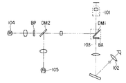
Thus, as a conventional epi-illumination microscope, as shown in FIG. 12, the first dichroic mirror disposed with the barrier filter BA in the observation optical system optical path 103 connecting the
[0007]
JP-A-8-234110 discloses, as an epifluorescence microscope, a first dichroic mirror DM1 for introducing excitation light from an
[0008]
[Problems to be solved by the invention]
However, in the conventional apparatus shown in FIG. 12, considering the
[0009]
On the other hand, what is disclosed in Japanese Patent Application Laid-Open No. 08-234110 is that when the first dichroic mirror DM1 is arranged closer to the sample than the second dichroic mirror DM2, for example, the laser wavelength range of the
[0010]
The present invention has been made in view of the above circumstances, and provides a versatile epifluorescence microscope that has a plurality of independent optical paths of the epi-illumination optical system, and uses of each epi-illumination optical path are not limited. With the goal.
[0011]
[Means for Solving the Problems]
According to an aspect of the present invention, an observation optical system optical path for the specimen in an epifluorescence microscope that enables optical manipulation and fluorescence observation of the specimen simultaneously by selectively irradiating the specimen with a plurality of epi-illumination lights. Crossing the observation optical system optical path at the same intersection point as the first epi-illumination optical system optical path of the observation optical system optical path and the first epi-illumination optical system optical path arranged in a direction intersecting with each other through the intersection A second epi-illumination optical system optical path arranged in a direction, and a third inter-axis arranged in a direction intersecting the observation optical system optical path via a different intersection with the first and second epi-illumination optical system optical paths It is comprised by the epi-illumination optical system optical path.
[0012]
Accordingly, for example, a laser light source for releasing the caged reagent in the first incident illumination optical system optical path, a mercury lamp for exciting light irradiation in the second incident illumination optical system optical path, and a laser in the third incident illumination optical system optical path. A laser light source for trapping or a mercury lamp for irradiating excitation light is arranged, and the first to third epi-illumination optical system optical paths are selected, and a laser light source for releasing the caged reagent and a mercury lamp for irradiating excitation light. In addition, by combining a laser light source for laser trapping, laser trap experiments such as Caged reagent release experiment by Caged release and fluorescence observation and capture of minute objects and measurement of micro force by fluorescence observation and laser trap can be selectively performed. .
[0013]
In the epi-illumination fluorescence microscope, it is desirable that wavelength separation means be detachably disposed at the intersection of the observation optical system optical path and the third epi-illumination optical system optical path.
[0014]
As a result, when only normal fluorescence observation is performed without performing laser trapping, for example, an observation image excluding light loss during weak fluorescence observation is obtained by excluding wavelength sorting means such as a dichroic mirror from the observation optical path. be able to. In addition, by inserting wavelength sorting means into the observation optical path, for example, a laser light source for laser traps arranged in the optical path of the third epi-illumination optical system or a laser for laser traps using a mercury lamp for irradiation of excitation light and a fluorescent light observation Since the excitation light can be selectively introduced into the optical path of the observation optical system, a laser trap experiment and a Caged reagent release experiment can be selectively performed as necessary in this case as well, thereby forming a versatile experimental system. be able to.
[0015]
In the epi-illumination fluorescent microscope, a fourth epi-illumination is provided in a direction intersecting the observation optical system optical path through an intersection different from the first and second epi-illumination optical system optical paths and the third epi-illumination optical system optical path. An optical path of the optical system may be arranged.
[0016]
Thus, for example, a laser light source for exciting light irradiation in the first epi-illumination optical system optical path, a mercury lamp for excitation light irradiation in the second epi-illumination optical system optical path, and a laser in the third epi-illumination optical system optical path. A laser light source for trapping is arranged, and further, a laser light source for releasing the Caged reagent is arranged in the fourth epi-illumination optical system optical path, the first to second epi-illumination optical system optical paths are selected, and the excitation light source mercury By selectively using a lamp and a laser light source and using a laser for laser trap and a laser for releasing the Caged reagent, the ultraviolet light is irradiated to any protein in the cell to release the Caged reagent and activate it. It is possible to perform operations such as trapping the irradiated protein by irradiating it with an infrared laser and analyzing the behavior of intracellular substances at the molecular level. It is possible to construct a highly effective experimental system in the field.
[0017]
DETAILED DESCRIPTION OF THE INVENTION
Hereinafter, embodiments of the present invention will be described with reference to the drawings.
[0018]
(First embodiment)
1 and 2 show a schematic configuration of an inverted epifluorescence microscope to which the present invention is applied. In the figure,
[0019]
The cube turret CT includes a cube CV1 having a dichroic mirror DM1 having an inclination of 45 ° with respect to the
[0020]
The cube turret CT shown in FIG. 1 shows only two cubes, but at least four cubes having the same configuration and the same shape as the cubes CV1 and CV1 ′ can be inserted / removed. The reflecting mechanism of the dichroic mirror of an arbitrary cube can be adjusted to the point O1 where the
[0021]
Then, the
[0022]
A slider SV indicated by a broken line is provided below the cube turret CT so as to be movable along an
[0023]
The slider SV has a dichroic mirror DM2 having a 45 ° inclination with respect to the
[0024]
Then, by moving the slider SV along the direction of the
[0025]
The switching stop position of the dichroic mirrors DM2 and DM2 ′ on the slider SV is set by a positioning mechanism (not shown).
[0026]
The
[0027]
In this case, a
[0028]
On the other hand, on the
[0029]
The observation light transmitted through the
[0030]
The light transmitted through the
[0031]
Next, the operation of the embodiment configured as described above will be described.
[0032]
Now, the
[0033]
First, as shown in FIG. 1, the cube CV1 of the cube turret CT is positioned on the
[0034]
In this state, N for releasing the Caged reagent having a wavelength of 337 nm of the
[0035]
On the other hand, in this state, the dichroic mirror DM2 of the cube CV2 of the slider SV is positioned at the point O2 where the
[0036]
Then, when fluorescence is emitted from the
[0037]
Thereby, Caged reagent cancellation | release and fluorescence observation can be performed simultaneously.
[0038]
Here, the characteristics of the dichroic mirrors DM1 and DM2 used when simultaneously releasing the Caged reagent and observing the fluorescence are summarized as follows.
[0039]
That is, the dichroic mirror DM1 reflects the laser light (wavelength of 400 nm or less) from the
[0040]
Next, as shown in FIG. 2, the cube turret CT is rotated in the direction indicated by the arrow to place the cube CV1 'on the
[0041]
In this state, mercury light having a wavelength of 488 nm for fluorescence observation of the
[0042]
Then, when fluorescence is emitted from the
[0043]
On the other hand, since the slider SV ′ is inserted on the
[0044]
Then, the laser beam incident on the
[0045]
As a result, it is possible to simultaneously perform fluorescence observation, capture of a minute object by a laser trap, measurement of a minute force, and the like.
[0046]
Here, the characteristics of the dichroic mirrors DM1 'and DM2' used when simultaneously performing fluorescence observation and capturing of a minute object by a laser trap and measurement of a minute force are summarized as follows.
[0047]
That is, the dichroic mirror DM1 ′ reflects the excitation light (wavelength of 500 nm or less) from the
[0048]
Accordingly, with such a configuration, the laser light from the
[0049]
In the first embodiment, the inverted microscope has been described. However, the first embodiment can also be applied to a general upright microscope. Further, the type, wavelength, number, and arrangement of the light sources used this time are not necessarily the same. Further, the intersection angle between each illumination optical system optical path and the observation optical system optical path (optical axis 31) is not necessarily 90 °, and may be different from each other. Furthermore, the characteristics of the dichroic mirror used this time do not necessarily have to be the same, and a dichroic prism or other appropriate wavelength sorting means may be applied as long as it is suitable for the wavelength characteristics of a desired light beam. Further, the insertion / removal mechanism of the dichroic mirror with respect to the optical axis may not be the same as that of the cube turret CT and the slider SV, and may be any other insertion / removal mechanism. Then, either one of the
[0050]
(Second Embodiment)
FIG. 7 shows a schematic configuration of the second embodiment of the present invention, and the same parts as those in FIG.
[0051]
In this case, FIG. 7 is obtained by removing the
[0052]
In short, the second embodiment configured as described above is obtained by removing the
[0053]
For this reason, the
[0054]
In this way, by removing dichroic mirrors and barrier filters that are not used in normal fluorescence observation that irradiates the specimen with only a single excitation light from the observation optical path, unused cubes are in the observation optical path. Fluorescence in a certain range of wavelength bands can be prevented in advance from an unexpected failure that is reflected and removed from the observation optical path. Further, by removing an extra optical element, it is possible to prevent a loss of light amount during weak fluorescence observation, and to prevent deterioration of an observation image that combines other fluorescence observation and other spectroscopic methods.
[0055]
If it is desired to use a laser trap with the configuration shown in FIG. 7, the cube CV2 of the slider SV in FIG. 7 is changed to a cube CV2 ′ as shown in FIG. The
[0056]
With such a configuration, laser trapping and fluorescence observation can be performed simultaneously, and the same effect as described above can be expected. In such an embodiment, the cube attached to the slider SV may be changed to another one according to the light source to be used.
[0057]
In the second embodiment, the inverted microscope has been described, but the present invention can also be applied to a general upright microscope. Further, the type, wavelength, number, and arrangement of the light sources used this time are not necessarily the same. Further, the intersection angle between each illumination optical system optical path and the observation optical system optical path (optical axis 31) is not necessarily 90 °, and may be different from each other. Furthermore, the characteristics of the dichroic mirror used this time do not necessarily have to be the same, and a dichroic prism or other appropriate wavelength sorting means may be applied as long as it is suitable for the wavelength characteristics of a desired light beam. Further, the insertion / removal mechanism of the dichroic mirror with respect to the optical axis may not be the same as that of the cube turret CT and the slider SV, and may be any other insertion / removal mechanism. Then, either one of the
[0058]
(Third embodiment)
FIG. 9 shows a schematic configuration of the third embodiment of the present invention, and the same parts as those in FIG.
[0059]
In this case, FIG. 9 is similar to FIG. 1 except that a slider SV ″ is provided by adding the
[0060]
In the third embodiment configured as described above, by switching the slider SV ″, the cubes CV2, CV2 ′ and the
[0061]
In this way, the effects described in the second embodiment can be obtained without impairing the effects described in the first embodiment. That is, in brief, it is possible to provide an inverted microscope that can selectively use various light beams only by simple switching and can be used as a normal inverted microscope.
[0062]
In the third embodiment, the inverted microscope has been described. However, the third embodiment can be applied to a general upright microscope. Further, the type, wavelength, number, and arrangement of the light sources used this time are not necessarily the same. Further, the intersection angle between each illumination optical system optical path and the observation optical system optical path (optical axis 31) is not necessarily 90 °, and may be different from each other. Furthermore, the characteristics of the dichroic mirror used this time do not necessarily have to be the same, and a dichroic prism or other appropriate wavelength sorting means may be applied as long as it is suitable for the wavelength characteristics of a desired light beam. Further, the insertion / removal mechanism of the dichroic mirror with respect to the optical axis may not be the same as that of the cube turret CT and the slider SV ″, and may be any other insertion / removal mechanism. , 19 need not be attached to the slider SV ″. For example, any one of the
[0063]
(Fourth embodiment)
FIG. 10 shows a schematic configuration of the fourth embodiment of the present invention, and the same parts as those in FIG.
[0064]
In this case, in FIG. 10, a point O4 is provided on the
[0065]
In the fourth embodiment configured as described above, the
[0066]
In other words, this makes it possible to add Caged reagent release when using fluorescence observation and a laser trap, and simultaneously using three light sources using the wavelength characteristics of each optical element described in the first embodiment. can do.
[0067]
As a result, while irradiating excitation light and observing fluorescence inside the cell, N 2 It is possible to release the Caged reagent by irradiating a laser, irradiate the activated protein with an IR laser to optically capture it, and measure the microforce, and the behavior of intracellular substances can be measured at the molecular level. It is very effective in the field of cell physiology analyzed in In other words, in the quest for specialized fields, there are many cases where it is desired to use various light sources at the same time. By adopting the configuration as shown in FIG. 10, the above-described apparatus having great academic merit is provided. Can do.
[0068]
In the fourth embodiment, the laser trap dichroic mirror DM2 ′ is disposed at the bottom of the other dichroic mirrors on the optical axis, but may be disposed at any position. A dichroic mirror on the optical axis may be added. Although the cube CV1 exists alone, a plurality of cubes may be inserted into and removed from the position of the cube CV1 using some mechanism.
[0069]
In the fourth embodiment, the inverted microscope has been described, but the present invention can also be applied to a general upright microscope. Further, the type, wavelength, number, and arrangement of the light sources used this time are not necessarily the same. Further, the intersection angle between each illumination optical system optical path and the observation optical system optical path (optical axis 31) is not necessarily 90 °, and may be different from each other. Furthermore, the characteristics of the dichroic mirror used this time do not necessarily have to be the same, and a dichroic prism or other appropriate wavelength sorting means may be applied as long as it is suitable for the wavelength characteristics of a desired light beam. Further, the insertion / removal mechanism of the dichroic mirror with respect to the optical axis may not be the same as that of the cube turret CT and the slider SV, and may be any other insertion / removal mechanism. Then, either one of the
[0070]
(Fifth embodiment)
As described above, each of the above-described embodiments can be applied to an upright microscope. Therefore, an embodiment in which the present invention is constituted by the upright microscope will be described with reference to FIG.
[0071]
FIG. 11 shows a schematic configuration of an embodiment in which the present invention is configured by an upright microscope. In the figure,
[0072]
The symbols attached to the components of the epi-illumination optical system on the objective lens side from the
[0073]
An optical path splitting prism Pr is disposed above the
[0074]
The operation of the embodiment configured in this way is exactly the same as the operation shown in the first embodiment, that is, the same effect can be obtained even in an upright microscope.
[0075]
As described above, what has been described in each embodiment is summarized as follows.
The epi-fluorescence microscope of the present invention is an epi-illumination fluorescence microscope that enables optical operation and fluorescence observation of a specimen at the same time by selectively irradiating the specimen with a plurality of epi-illumination lights. The first incident illumination optical system optical path disposed in a direction intersecting with the intersection, and the direction intersecting the observation optical system optical path at the same intersection as the first incident illumination optical path of the observation optical system optical path A second epi-illumination optical system optical path, a cube having a first dichroic mirror, and a cube having a second dichroic mirror, the observation optical system optical path and the first and second epi-illumination optical systems A first movable body that allows a desired cube to be inserted / removed at an intersection with the optical path, and an observation optical system optical path through an intersection different from the first and second epi-illumination optical system optical paths. And a cube having a third epi-illumination optical system optical path disposed in a crossing direction and a third dichroic mirror, and the cube at the intersection of the observation optical system optical path and the third epi-illumination optical system optical path And a second movable body that is detachably disposed.
[0076]
In the epi-fluorescence microscope, the first dichroic mirror reflects light from the first epi-illumination optical system optical path toward the specimen and transmits fluorescence emitted from the specimen. desirable. The second dichroic mirror preferably reflects light emitted from the second epi-illumination optical system optical path toward the sample and transmits fluorescence emitted from the sample. The third dichroic mirror desirably reflects light from the third epi-illumination optical system optical path toward the sample while transmitting fluorescence emitted from the sample.
[0077]
In the epi-fluorescence microscope, the first movable body is, for example, a cube turret. The second movable body is a slider, for example.
[0078]
The epi-fluorescence microscope may further include a laser light source that forms the first epi-illumination optical system optical path. The epifluorescence microscope may further include a mercury light source that forms the second epi-illumination optical system optical path. The epi-fluorescence microscope may further include at least one of a laser light source and a mercury light source that form the third epi-illumination optical system optical path.
[0079]
The epi-illumination fluorescent microscope may further include a fourth epi-illumination optical system optical path arranged in a direction intersecting the third epi-illumination optical system optical path via an intersection. In this case, the incident-light fluorescent microscope may further include a slider that removably arranges a total reflection mirror at the intersection of the third incident-light illumination optical system optical path and the fourth incident-light illumination optical system optical path. Good.
[0080]
【The invention's effect】
As described above in detail, according to the present invention, there are a plurality of independent optical paths of the epi-illumination optical system, these epi-illumination optical system optical paths are selected, the laser light source for releasing the Caged reagent, and the mercury for excitation light irradiation. By combining a lamp, a laser light source for a laser trap, and the like, it is possible to provide a versatile epifluorescence microscope in which the use of each epi-illumination light path is not limited.
[Brief description of the drawings]
FIG. 1 is a diagram showing a schematic configuration of a first embodiment of the present invention.
FIG. 2 is a diagram showing a schematic configuration of the first embodiment.
FIG. 3 is a diagram showing spectral transmittance characteristics of a dichroic mirror DM1 used in the first embodiment.
FIG. 4 is a spectral transmittance characteristic diagram of a dichroic mirror DM2 ′ used in the first embodiment.
FIG. 5 is a spectral transmittance characteristic diagram of the dichroic mirror DM2, the excitation filter EX2, and the barrier filter BA2 used in the first embodiment.
FIG. 6 is a spectral transmittance characteristic diagram of a dichroic mirror DM1 ′, an excitation filter EX1 ′, and a barrier filter BA1 ′ used in the first embodiment.
FIG. 7 is a diagram showing a schematic configuration of a second embodiment of the present invention.
FIG. 8 is a diagram showing a schematic configuration obtained by partially modifying the second embodiment.
FIG. 9 is a diagram showing a schematic configuration of a third embodiment of the present invention.
FIG. 10 is a diagram showing a schematic configuration of a fourth embodiment of the present invention.
FIG. 11 is a diagram showing a schematic configuration of a fifth embodiment of the present invention.
FIG. 12 is a diagram showing a schematic configuration of an example of a conventional epifluorescence microscope.
FIG. 13 is a diagram showing a schematic configuration of another example of a conventional epi-fluorescence microscope.
[Explanation of symbols]
1 ... Sample,
2 ... Objective lens,
3 ... Laser light source,
4 ... Collector lens,
5 ... Relay lens,
6 ... mercury light source,
7 ... Collector lens,
8 ... Relay lens,
9 ... Mercury light source,
10 ... collector lens,
11 ... Relay lens,
12 ... Laser light source,
13 ... Collector lens,
14 ... Total reflection mirror,
15, 16 ... imaging lens,
17 ... Half prism,
18 ... Total reflection mirror,
19 ... imaging lens,
20 ... Laser light source,
21 ... Collector lens,
22 ... Relay lens,
31, 32, 33, 34, 35 ... optical axis,
BA1 ', BA1 ", BA2 ... barrier filter,
CT ... Cube turret,
CV1, CV1 ', CV1 ", CV2, CV2' ... Cube,
DM1, DM1 ', DM2, DM2' ... Dichroic mirror,
EX1 ', EX2 ... excitation filter,
Oc ... eyepiece,
Ph: light receiving surface,
Pr: optical path splitting prism,
R1 ... Relay lens,
SV, SV ′, SV ″... Slider.
Claims (3)
前記標本に対する観察光学系光路に交点を介して交差する方向に配置された第1の落射照明光学系光路と、
前記観察光学系光路の前記第1の落射照明光学系光路と同一の交点で前記観察光学系光路と交差する方向に配置された第2の落射照明光学系光路と、
前記観察光学系光路に、前記第1および第2の落射照明光学系光路と異なる交点を介して交差する方向に配置された第3の落射照明光学系光路と
を具備したことを特徴とする落射蛍光顕微鏡。In the epi-fluorescence microscope that enables simultaneous optical operation of the specimen and fluorescence observation by selectively irradiating the specimen with multiple epi-illumination lights.
A first epi-illumination optical system optical path disposed in a direction intersecting the observation optical system optical path with respect to the specimen via an intersection;
A second epi-illumination optical system optical path disposed in a direction intersecting the observation optical system optical path at the same intersection as the first epi-illumination optical system optical path of the observation optical system optical path;
The observation optical system optical path includes a third epi-illumination optical system optical path disposed in a direction intersecting with the first and second epi-illumination optical system optical paths through an intersection point different from the first and second epi-illumination optical system optical paths. Fluorescence microscope.
Priority Applications (1)
| Application Number | Priority Date | Filing Date | Title |
|---|---|---|---|
| JP30223798A JP4222664B2 (en) | 1997-10-24 | 1998-10-23 | Epi-illumination microscope |
Applications Claiming Priority (3)
| Application Number | Priority Date | Filing Date | Title |
|---|---|---|---|
| JP9-292446 | 1997-10-24 | ||
| JP29244697 | 1997-10-24 | ||
| JP30223798A JP4222664B2 (en) | 1997-10-24 | 1998-10-23 | Epi-illumination microscope |
Publications (2)
| Publication Number | Publication Date |
|---|---|
| JPH11223773A JPH11223773A (en) | 1999-08-17 |
| JP4222664B2 true JP4222664B2 (en) | 2009-02-12 |
Family
ID=26558992
Family Applications (1)
| Application Number | Title | Priority Date | Filing Date |
|---|---|---|---|
| JP30223798A Expired - Fee Related JP4222664B2 (en) | 1997-10-24 | 1998-10-23 | Epi-illumination microscope |
Country Status (1)
| Country | Link |
|---|---|
| JP (1) | JP4222664B2 (en) |
Families Citing this family (8)
| Publication number | Priority date | Publication date | Assignee | Title |
|---|---|---|---|---|
| JP4608043B2 (en) * | 1999-09-24 | 2011-01-05 | オリンパス株式会社 | Microscope focus detector |
| JP3999479B2 (en) | 2001-07-10 | 2007-10-31 | オリンパス株式会社 | Optical device |
| JP4503247B2 (en) * | 2003-06-23 | 2010-07-14 | 株式会社キーエンス | Fluorescence microscope |
| JP5445135B2 (en) | 2007-11-27 | 2014-03-19 | 株式会社ニコン | Fluorescence microscope |
| JP5988629B2 (en) * | 2012-03-14 | 2016-09-07 | オリンパス株式会社 | Microscope with multiple optical units |
| JP2013231855A (en) * | 2012-04-27 | 2013-11-14 | Olympus Corp | Inverted microscope |
| DE102016119727A1 (en) | 2016-10-17 | 2018-04-19 | Carl Zeiss Microscopy Gmbh | Device for beam manipulation for a scanning microscope and microscope |
| CN120800270B (en) * | 2025-08-13 | 2026-02-06 | 蓝星光域(上海)航天科技有限公司 | Method and device for measuring orthogonality of orthogonal rotation axis |
-
1998
- 1998-10-23 JP JP30223798A patent/JP4222664B2/en not_active Expired - Fee Related
Also Published As
| Publication number | Publication date |
|---|---|
| JPH11223773A (en) | 1999-08-17 |
Similar Documents
| Publication | Publication Date | Title |
|---|---|---|
| USRE38847E1 (en) | Reflected fluorescence microscope with multiple laser and excitation light sources | |
| JP4521155B2 (en) | Microscope image processing device | |
| JP5006694B2 (en) | Lighting device | |
| JP5286774B2 (en) | Microscope device and fluorescent cube used therefor | |
| JP2000056228A (en) | System for wavelength-dependent detection used in laser scanning microscope and image recording method | |
| JP2001166214A (en) | Optical device | |
| JP4222664B2 (en) | Epi-illumination microscope | |
| JP4270884B2 (en) | Microscope system | |
| JP4854880B2 (en) | Laser microscope | |
| US7016101B2 (en) | Scanning microscope and optical element | |
| JP2006235624A (en) | Laser microdissection unit | |
| US20060087727A1 (en) | Apparatus, system and method for selective photobleaching, imaging and confocal microscopy | |
| JP2002098899A (en) | Fluorescent microscope | |
| JP4172212B2 (en) | Microscope specimen illumination method and microscope having illumination apparatus using the same | |
| JP2013041142A (en) | Microscopic device | |
| JP2003057556A (en) | Mirror driving mechanism, and spectroscopic device and scanning laser microscope provided with mirror driven by mirror driving mechanism | |
| JP3339244B2 (en) | Epi-fluorescence microscope | |
| JP4258814B2 (en) | Microscope illumination device | |
| JP2006003747A (en) | Optical scanning type observation apparatus | |
| JP2005337729A (en) | Microscope observation method, photo-stimulus device, and microscope observation device | |
| JP3872856B2 (en) | Fluorescence microscope | |
| JP3405252B2 (en) | Biological sample observation device | |
| JP4869606B2 (en) | Laser light irradiation device and microscope device with laser light irradiation device | |
| JP2009282103A (en) | Confocal scanner microscope | |
| JP2003270147A (en) | Molecule detector |
Legal Events
| Date | Code | Title | Description |
|---|---|---|---|
| A621 | Written request for application examination |
Free format text: JAPANESE INTERMEDIATE CODE: A621 Effective date: 20050928 |
|
| TRDD | Decision of grant or rejection written | ||
| A01 | Written decision to grant a patent or to grant a registration (utility model) |
Free format text: JAPANESE INTERMEDIATE CODE: A01 Effective date: 20081028 |
|
| A01 | Written decision to grant a patent or to grant a registration (utility model) |
Free format text: JAPANESE INTERMEDIATE CODE: A01 |
|
| A61 | First payment of annual fees (during grant procedure) |
Free format text: JAPANESE INTERMEDIATE CODE: A61 Effective date: 20081118 |
|
| FPAY | Renewal fee payment (event date is renewal date of database) |
Free format text: PAYMENT UNTIL: 20111128 Year of fee payment: 3 |
|
| FPAY | Renewal fee payment (event date is renewal date of database) |
Free format text: PAYMENT UNTIL: 20111128 Year of fee payment: 3 |
|
| FPAY | Renewal fee payment (event date is renewal date of database) |
Free format text: PAYMENT UNTIL: 20121128 Year of fee payment: 4 |
|
| FPAY | Renewal fee payment (event date is renewal date of database) |
Free format text: PAYMENT UNTIL: 20131128 Year of fee payment: 5 |
|
| LAPS | Cancellation because of no payment of annual fees |