EP2660608A1 - Centrifugal separation device, pretreatment system provided with centrifugal separation device, and control method for the system - Google Patents
Centrifugal separation device, pretreatment system provided with centrifugal separation device, and control method for the system Download PDFInfo
- Publication number
- EP2660608A1 EP2660608A1 EP11853226.6A EP11853226A EP2660608A1 EP 2660608 A1 EP2660608 A1 EP 2660608A1 EP 11853226 A EP11853226 A EP 11853226A EP 2660608 A1 EP2660608 A1 EP 2660608A1
- Authority
- EP
- European Patent Office
- Prior art keywords
- specimen
- adaptor
- buckets
- specimen container
- container
- Prior art date
- Legal status (The legal status is an assumption and is not a legal conclusion. Google has not performed a legal analysis and makes no representation as to the accuracy of the status listed.)
- Granted
Links
Images




Classifications
-
- G—PHYSICS
- G01—MEASURING; TESTING
- G01N—INVESTIGATING OR ANALYSING MATERIALS BY DETERMINING THEIR CHEMICAL OR PHYSICAL PROPERTIES
- G01N35/00—Automatic analysis not limited to methods or materials provided for in any single one of groups G01N1/00 - G01N33/00; Handling materials therefor
- G01N35/02—Automatic analysis not limited to methods or materials provided for in any single one of groups G01N1/00 - G01N33/00; Handling materials therefor using a plurality of sample containers moved by a conveyor system past one or more treatment or analysis stations
- G01N35/04—Details of the conveyor system
-
- B—PERFORMING OPERATIONS; TRANSPORTING
- B04—CENTRIFUGAL APPARATUS OR MACHINES FOR CARRYING-OUT PHYSICAL OR CHEMICAL PROCESSES
- B04B—CENTRIFUGES
- B04B13/00—Control arrangements specially designed for centrifuges; Program control of centrifuges
-
- B—PERFORMING OPERATIONS; TRANSPORTING
- B04—CENTRIFUGAL APPARATUS OR MACHINES FOR CARRYING-OUT PHYSICAL OR CHEMICAL PROCESSES
- B04B—CENTRIFUGES
- B04B9/00—Drives specially designed for centrifuges; Arrangement or disposition of transmission gearing; Suspending or balancing rotary bowls
- B04B9/14—Balancing rotary bowls ; Schrappers
-
- B—PERFORMING OPERATIONS; TRANSPORTING
- B04—CENTRIFUGAL APPARATUS OR MACHINES FOR CARRYING-OUT PHYSICAL OR CHEMICAL PROCESSES
- B04B—CENTRIFUGES
- B04B9/00—Drives specially designed for centrifuges; Arrangement or disposition of transmission gearing; Suspending or balancing rotary bowls
- B04B9/14—Balancing rotary bowls ; Schrappers
- B04B9/146—Imbalance detection devices
-
- B—PERFORMING OPERATIONS; TRANSPORTING
- B04—CENTRIFUGAL APPARATUS OR MACHINES FOR CARRYING-OUT PHYSICAL OR CHEMICAL PROCESSES
- B04B—CENTRIFUGES
- B04B11/00—Feeding, charging, or discharging bowls
- B04B11/04—Periodical feeding or discharging; Control arrangements therefor
- B04B2011/046—Loading, unloading, manipulating sample containers
Definitions
- the present invention relates to an automatic centrifuge for performing centrifugal process to a specimen inside a pre-analysis system, and, more particularly, the present invention relates to a pre-analysis system, a specimen-test automation system, and control techniques of the systems capable of avoiding unbalanced operation due to a weight difference upon the centrifugal process.
- test specimens of hospital inpatients and outpatients are collected in each department in the hospital, and are collectively processed in a test room.
- a test item for each specimen is transferred from a doctor to the test room by using an online information processing system, and a result of the test is reversely reported online from the test room to the doctor.
- Most of test items for blood and urine require pre-analysis processing such as centrifugal processing, decap processing, and dispensing processing as the pre-analysis processing of the test processing, and a rate occupied in the entire test operation time by the operation for them is large.
- the centrifugal processing of the pre-analysis processing is a processing for extracting serum components by performing centrifugation to the blood collected from a patient so as to obtain a test sample.
- an automatic centrifuge used in a specimen-test automation system has a plurality of bucket groups held by a rotating rotor so as to be swung.
- Each of the bucket groups is configured of a plurality of pair of buckets, and each of the pair of buckets is configured of buckets positioned rotation-symmetrically to each other across a rotation axis of the rotor.
- a plurality of (for example, about 5 to 10) specimens are inserted while they are set on an adaptor and are held so as to stand up.
- the specimens have been inserted into the respective buckets by a human hand.
- an aim of a specimen-test automation system in which the pre-analysis processing is automated is to automate these operations.
- the centrifugal operation is performed by rotating the rotor at high speed. Therefore, if weights of the buckets arranged at the pair of buckets are significantly different from each other, the rotation abnormality of the rotor is caused, and the centrifugal operation cannot be normally performed. Therefore, it is required to execute weight adjustment at a prior stage to installation at the rotor.
- Patent Document 1 a weight called dummy rack is used to reduce a weight difference between the buckets.
- Patent Document 2 discloses a technique in which weights of all racks are previously measured, and they are stocked once, and a pair of racks having a weight difference therebetween within a predetermined amount are selected from a group of the stocked racks and are inserted into the pair of buckets.
- Patent Document 2 discloses a technique in which the difference in the weight between the adaptors positioned symmetrically to each other is minimized by providing a specimen-container weight-measurement mechanism in an automatic centrifuge, and repeating to compare total weights of the adaptors (adaptors A and B) with each other placed on a pair of buckets positioned symmetrically to each other across a centrifugal rotation center of a rotor so as to place a next specimen container on the adaptor B if the adaptor A is heavier, conversely, so as to place the next specimen container on the adaptor A if the adaptor B is heavier, and to compare the weights of the adaptors A and B again, until there is no vacant position on either one of the adaptors.
- control is performed so as to execute the centrifugal processing after a certain period of time has passed in many cases even if there is vacancy on the adaptor. At that time, if the setting states of the specimen containers on the respective adaptors are unbalanced, the gravity center in the adaptors is similarly shifted, and this can be similarly a cause of the rotation abnormality of the rotor.
- a specimen whose volume is a certain volume or more is required for such a pre-analysis processing as the centrifugal processing and the dispensing processing.
- the specimen dispensing is performed from the specimen container, and lack of the specimen is recognized, and then, lack of the specimen volume is finally recognized, and the specimen is conveyed out from the device as the abnormality in the specimen. Then, a user takes such an action as addition of the specimen, and loads the specimen into the device again.
- the recognition of abnormality in the specimen is late, and therefore, report delay of the measurement result is finally extended.
- the present invention has been made in consideration of the above-described conventional problems, and a preferred aim thereof is to provide a specimen-test automation system capable of performing normal centrifugal operation and minimizing result report delay of an abnormal specimen without reducing processing performance of an automatic centrifuge by correctly recognizing a weight of a specimen loaded into the specimen-test automation system at a prior stage to conveying of the specimen to a specimen processing unit.
- the specimen-test automation system has a feature that a detecting container weight-measurement mechanism for measuring a weight of the specimen container is arranged on the conveyor line that connects between the loading module and the specimen processing unit.
- a detecting container weight-measurement mechanism for the specimen loaded from the loading module, the weight of the specimen container is measured by the specimen-container weight-measurement mechanism on the conveyor line, and the specimen container is conveyed to the automatic centrifuge.
- the specimen container conveyed to the automatic centrifuge stands by without being set at an adaptor until the number of specimens which can be subjected to the centrifugal processing at once arrive.
- the maximum number of specimens which can be subjected to the centrifugal processing arrive at the automatic centrifuge, if it is assumed that the adaptors placed on a pair of buckets symmetrically positioned to each other across the centrifugal rotation center of a rotor are adaptors A and B, the weights of the adaptors A and B are compared with each other, and the heaviest specimen container among the specimen containers which have not been set yet is set at the adaptor whose total weight is lighter.
- FIG. 1 illustrates an example of a setting order of the specimen containers at the adaptor.
- a technique of setting the specimen containers will be explained with reference to the present drawing.
- FIG. 1 an example of the adaptor at which nine specimen containers can be set is cited.
- the container is set at the center of the adaptor first (see (A) in FIG. 1 ).
- the center of the adaptor described here refers to a position which is the closest to a gravity-center position of the adaptor and at which the specimen container can be installed.
- the second specimen container is set at a position close to the center of the adaptor (see (B) in FIG. 1 ).
- the third specimen container is set at a position which is a point of symmetry across the adaptor center with respect to the second test tube (see (C) in FIG. 1 ).
- the specimen containers are set on a supporting shaft of the bucket on which the adaptor is set.
- the arrangement is repeated (see (D) to (H) in FIG. 1 ) so that the specimen containers are set sequentially from the center of the adaptor (see (I) in FIG. 1 ). Also in this case, the setting is sequentially performed at a position which is a point of symmetry across the adaptor center.
- the technique in which the specimen containers are installed at the adaptor sequentially in an order from the heavier weight after the maximum number of specimens which can be subjected to the centrifugal processing arrive at the automatic centrifuge has been described.
- the setting of the specimen containers at the adaptor may be started sequentially in an order from the heavier weight at a moment when a previously-input timeout period has passed.
- the specimen-container weight-measurement mechanism may be provided inside the automatic centrifuge so as to measure the specimen weight after the specimen is conveyed to the automatic centrifuge.
- the specimen containers are allocated to the respective adaptors in the order from the heavier specimen container by the present means, the difference in the weight between the adaptors placed on the respective buckets to be paired is minimized, and the sift of the gravity center of the adaptor is minimized because the heavy specimen container is set on an inner side of the adaptor, so that stable centrifugal processing can be achieved.
- the weight of the specimen container is measured by the specimen-container weight-measurement mechanism on the conveyor line.
- the adaptors placed on the pair of buckets positioned symmetrically to each other across the centrifugal rotation center of the rotor of the automatic centrifuge are referred to as the adaptors A and B, the weights of the adaptors A and B are compared with each other, and the specimen container is set at the adaptor whose total weight is lighter.
- the unequal weight balance between the adaptors to be paired of the automatic centrifuge can be previously prevented, so that the centrifugal processing can be normally performed.
- the number of the specimens which can be subjected to the centrifugal processing at once can be increased, so that the reduction in the processing performance can be prevented.
- a holder at which no specimen is set is conveyed to the specimen-container weight-measurement mechanism, and a weight of only the holder is measured.
- a measurement result thereof is stored in a storage medium included in the holder.
- a storage technique may be a technique in which the holder weight is stored in the holder itself by providing a RFID (radio frequency identification) in the holder or a technique in which, by pasting a bar code on the holder, the bar-code information and the holder weight are stored in a control computer of the specimen-test automation system.
- the weight of the holder at which the specimen container is actually set is measured.
- the weight of the specimen container is obtained by subtracting the previously-measured holder weight from the measured weight.
- the weight of the specimen container can be correctly measured by correctly recognizing the weight of each of the holders, and the normal centrifugal processing can be performed by determining a setting destination of the specimen container in the automatic centrifuge based on the correct weight.
- the specimen-container weight-measurement mechanism When the holder at which the specimen container is set is measured by the specimen-container weight-measurement mechanism, it is checked whether or not the measured weight is within a range of a previously-set normal specimen weight. If it is within the range, it is determined that the specimen having a normal volume is contained in the specimen container, and the subsequent pre-analysis processing is performed. However, if it is out of the range of the normal specimen weight, the specimen is regarded as the abnormal specimen, and the specimen is collected to the housing module.
- the specimen containers have a different container weight from each other depending on differences in a container diameter and a specimen-container length, and therefore, the range of the normal specimen weight is also different depending on a category of the specimen container. Accordingly, the shape of the specimen container is recognized, the normal specimen weight that matches the shape of the specimen container is selected, and then, it is determined whether the specimen can be used or not. As means for recognizing the shape of the specimen container, for example, a CCD camera may be used.
- such abnormality in the specimen that a specimen volume is small can be detected prior to processing in the pre-analysis module, so that the specimen can be early collected.
- a user takes an action for the abnormal specimen at an early stage, and loads a specimen again into the specimen-test pre-analysis system, so that result report delay can be suppressed at a minimum.
- a weight of a specimen loaded into a specimen-test automation system is correctly recognized at a prior stage to conveying to a specimen processing unit, so that normal centrifugal operation can be performed, and result report delay of an abnormal specimen can be minimized.
- FIG. 2 An overall view related to a specimen-rack conveyor line unit of a specimen-test pre-analysis system according to the present invention is illustrated in FIG. 2 .
- a holder 31 has a structure in which it can be conveyed on a line while it stands up a specimen container 32 in which body fluid such as blood collected from a patient has been injected, and the holders 31 are provided with unique ID numbers, respectively.
- the holders 31 convey between respective processing modules by a plurality of conveyor lines which take respective charges of usage. Next, a flow of the specimens in the system will be described.
- a tray 33 in which 50 to 100 specimen containers 32 can be installed is installed in a loading module 102.
- the specimen containers 32 in the tray 33 are transferred to the holder 31 by a test-tube chuck mechanism not illustrated.
- the holders 31 are previously stored in vicinity of an outlet of a rack stocker 101, and the holders 31 are sequentially conveyed to the loading module 102 in accordance with a conveying request made by communication from the loading module 102.
- the bar-code information pasted on the specimen container 32 is read in the loading module 102.
- the read bar-code information is transferred to a host computer 51, and category information of the specimen which is registered in the host computer 51 is returned to the system.
- a specimen-container weight-measurement mechanism 20 for the weight measurement is arranged on a main conveyor line 11, and total weights of the specimen container 32 and the holder 31 are measured at the position. For each specimen, a result of the total weight measurement is transmitted to a control computer 41 together with an ID number of the holder 31.
- the control computer 41 determines a processing module by which the holder is to be stopped or a processing module which is to be skipped based on the category information returned from the host computer 51 and the above-described measured specimen weight information, and conveys the specimen container 32 placed on the holder 31 is conveyed to the respective processing modules 104 and 105.
- the specimen container 32 for which all processing ends is finally conveyed to a housing module 103, and the specimen container 32 is removed from the holder 31 by the test-tube chuck mechanism not illustrated and is housed in the tray 33.
- the vacant holder 31 from which the holder 31 has been removed is conveyed to the rack stocker 101.
- the main conveyor line 11 is a line for conveying the specimen containers 32, which have been loaded into the system, to the respective processing modules.
- An emergency overtaking line 12 is a line for making an emergency specimen overtake. And, with the emergency overtaking line 12, the specimen which is not required to stop by the processing module (for example, a specimen which is not required to be centrifuged, or others) can be bypassed by using branch lines 16 and 17 arranged at the respective processing modules.
- a return line 13 is a conveyor line for looping (circulating) the specimen containers 32 inside the system. For example, in a case of re-dispensing for a retest or others, the specimen container is looped (circulated) inside the system by using this return line 13.
- Vacant-rack conveyor lines 14a and 14b are provided so as to be in parallel to the main conveyor line 11 and so as to have the same line length therewith, and are arranged between the return line 13 and the main conveyor line 11.
- the state that the vacant-rack conveyor lines 14a and 14b have the same line length as those of the main conveyor line 11 and the return line 13 aims at easiness of the system scalability (addition or reduction of the processing module). More specifically, the aim is to provide an optimum number as the number of vacant racks in accordance with the system scale.
- the number of vacant racks originally required for the processing in the system is a number thereof by which all of the lines are filled with the holders 31.
- the number of holders more than required for filling all of the lines is unnecessary.
- a line length obtained by addition of those of the main conveyor line 11 and the return line 13 is equal to a length obtained by addition of those of the vacant-rack conveyor lines 14a and 14b, and the vacant racks required for the system can be stored in the vacant-rack conveyor lines 14a and 14b. In this manner, the optimum number of vacant holders can be always provided in accordance with the system scale.
- this vacant-rack conveyor line 14a conveys the vacant holder which is continuously conveyed from the housing module 103 in order to efficiently collect the vacant holder so that the lines do not cross each other inside the rack stocker 101.
- the vacant-rack conveyor line 14b also conveys the vacant holder in a direction opposite to that of the return line 13.
- FIG. 3 illustrates a perspective view of an overall configuration of the centrifugal processing unit according to the present invention among the above-described processing modules
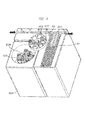
- FIG. 4 illustrates a perspective view from which an upper part thereof is removed.
- Main components of the centrifugal processing unit include: a centrifugal buffer line 201 on which a plurality of specimen containers 32 are temporarily stood by; a turn table 202 which holds the adaptor 210; and an automatic centrifuge 203 which centrifuges the specimen.
- the centrifugal processing is performed while the adaptor 210 is held by the bucket inside the turn table.
- the lateral sides of the bucket are held by a bucket supporting shaft 01. Therefore, when the turn table 202 is rotated, the adaptor held by the bucket is supported so that a bottom portion of the specimen container is directed toward an outside of the turn table 202 and so that an opening portion of the specimen container is tilted toward a rotation central axis of the turn table 202.
- the specimen containers 32 are sequentially conveyed by a belt line from a previous-process unit into a centrifugal buffer line 201 one by one while being supported by the holders 31.
- the holders 31 sequentially continue the conveying to a center of the centrifugal buffer line.
- the specimen container 32 is transferred to the adaptor 210 on the turn table 202 by a specimen chuck mechanism 204.
- the number of adaptors which is twice the number of buckets or larger which can be subjected to the centrifugal processing by the automatic centrifuge 203 at once can be installed on the turn table 202.
- the number of buckets which are subjected to the centrifugal processing by the automatic centrifuge 203 at once is four, eight which is twice the number is described as the number of adaptors.
- the specimen container can be transferred from the holder 31 to the adaptor 210 or the operation for the specimen return from the adaptor 210 to the holder 31 can be performed, so that reduction in the throughput of the entire process can be prevented.
- the turn table 202 has a rotary drive motor, and rotates while installing the adaptor 210, and is controlled so as to stop at an arbitrary position.
- the specimen chuck mechanism 204 is fixed to an XYZ mechanism 206 which is movable in a horizontal direction and a vertical direction, and transfers the specimen between the holder 31 and the adaptor 210.
- this XYZ mechanism 206 has an adaptor chuck mechanism 205 which conveys the adaptor 210 into the bucket of the automatic centrifuge.
- the automatic centrifuge 203 has: a high-speed-rotation drive motor for the centrifugation although not illustrated; a rotor 208 attached to this motor; and a plurality of buckets 207 attached symmetrically to each other across the rotation central axis of the rotor 208.
- the adaptor 210 After the transferring operation of the specimen container 32, which is to be subjected to the centrifugal processing, to the adaptor 210 is completed, the adaptor 210 is inserted into the bucket 207 by the adaptor chuck mechanism 205 while placing the specimen container 32 thereon. After the operations for inserting the adaptors 210 into all the buckets 207 is completed, a safety shutter 209 is closed, then, the centrifugal operation is started. During the centrifugal operation, the operations for removing the specimen container 32 from the holder 31 and inserting the container into the adaptor 210 are continued as preparation for the centrifugal operation in a next cycle. After the centrifugal operation is completed, a reverse process to the above-described operations is promoted. First, the safety shutter 209 is opened, and the adaptor 210 is returned from the bucket 207 to the turn table 202 by the adaptor chuck mechanism 205.
- the turn table 202 In order to shorten the waiting time of the automatic centrifuge 203, it is desired to return all the adaptors 210 for which the centrifugation operation has been completed to the turn table 202 and to continuously insert the adaptor 210 for the next centrifugal operation into the bucket 207.
- the turn table 202 In order to minimize a return distance from the adaptor 210 to the holder 31, the turn table 202 is rotated. After the turn table 202 stops, the specimen container is returned from the specimen adaptor 210 to the holder 31 by the specimen chuck mechanism 204. The specimen container 32 returned to the holder 31 is conveyed to a next process by the belt line.
- FIG. 5 illustrates a process flow from the loading of the specimens to the setting of the specimens at the adaptors 210 of the automatic centrifuge.
- the weight of the specimen container 32 is measured while being set in the holder 31 by a specimen-container weight-measurement mechanism 20 on the main conveyor line 11 in a step 501, and the specimen container is conveyed to the automatic centrifuge in a step 502.
- the specimen chuck mechanism 204 stands by without setting the specimen container 32 at the adaptor 210 until the number of the specimen containers 32 conveyed to the automatic centrifuge reaches the maximum number of specimens which can be subjected to the centrifugal processing at once (in a step 503).
- the conveying to the adaptor may be started in the order from the heaviest one at the moment among the specimens standing by on the centrifugal buffer line 201.
- the heaviest specimen container among all of the specimen containers conveyed into the automatic centrifuge is set at an adaptor A (in a step 504) in assumption that the above-described adaptors 210 placed on the pair of buckets positioned symmetrically to each other across the centrifugation rotation center of the rotor are adaptors A and B.
- step 505 the total weights of the adaptor A and the adaptor B are compared with each other in a step 505
- the heaviest specimen container among the specimen containers is set at the adaptor A if the adaptor A is lighter in a step 506
- the heaviest specimen container among the specimen containers is set at the adaptor B if the adaptor B is lighter in a step 507.
- step 505 to step 507 are repeated.
- FIG. 1 illustrates the setting order of the specimen containers at the adaptor in a case that the number of specimens set at the adaptor is nine as an example.
- the heaviest specimen container on the centrifugal buffer line is selected, and is installed at a center position of the specimen installation positions of the adaptor A (which is a position 1 of FIG. 1-A ).
- the total weights of the adaptor A and the adaptor B are compared with each other, and it is determined which adaptor the next heaviest specimen container is to be installed at. In the present embodiment, for example, if the total weight of the adaptor B is lighter, the next specimen is installed at the position 1 of the adaptor B in the step 507.
- the total weights of the adaptor A and the adaptor B are compared with each other, and the heavier specimen container is sequentially installed at the adaptor.
- the specimen containers to be installed at the adaptor A will be focused on, and the installation positions for the specimen containers will be explained.
- the next specimen container is installed at either a position 2 or a position 3 as the position having the short distance from the position 1 which is the center position of the adaptor.
- the specimen containers are installed in the order of the position 2, the position 3, the position 4, and the position 5.
- the positions 4 and 5 note that it does not matter that the specimen container is set at either one of them first.
- the third specimen container is set at a position which is a point of symmetry with respect to the second specimen container across the center (the first specimen container).
- the specimen container is set at a position which is a point of symmetry with respect to the fourth specimen container across the center.
- the specimen container is installed at any of positions 6 to 9 as a position having a long distance from the position 1. While the specimen containers are installed in the order of the position 6, the position 7, the position 8, and the position 9 in the present embodiment, other orders may be employed. Further, in the installation of the seventh specimen container, the seventh specimen container is set at a position which is a point of symmetry with respect to the sixth specimen container across the center. Similarly, in the installation of the ninth specimen container, the ninth specimen container is set at a position which is a point of symmetry with respect to the eighth specimen container across the center.
- the installation positions for the specimen containers are symmetric across the rotation axis of the rotor.
- the adaptor A is in the (B) state in FIG. 1 and the adaptor B is in the (A) state in FIG. 1
- the specimen container is to be installed at the adaptor B in a next turn
- the adaptor A is in the (D) state in FIG. 1 and the adaptor B is in the (C) state in FIG.
- the specimen container when the specimen container is to be installed at the adaptor B in a next turn, it is preferred to install the specimen container at a position symmetrically to the position 4 across the rotor rotation axis, that is, at the position 5.
- the stable rotation can be achieved even if the conveying of the specimen container to the adaptor is started before the specimen containers are conveyed into the centrifugal buffer line 201 so that the number thereof is the maximum number of the specimen containers which can be installed at the pair of buckets, since the gravity-center positions of the pair of buckets are the symmetric positions to each other across the rotor rotation axis.
- the present invention can be applied to even an automatic centrifuge in which two or more buckets can be subjected to the centrifugal processing. If the difference in the weight between the buckets positioned symmetrically to each other across the rotor rotation axis is not large, the stable centrifugal operation can be achieved, and therefore, the specimen containers are installed at the pair of buckets of the bucket A and the bucket B positioned symmetrically to each other across the rotor rotation axis first while balancing their weights, and then, the specimen containers are installed at other pair of buckets (bucket C and bucket D) positioned symmetrically to each other across the rotor rotation axis while balancing their weights. By sequentially installing the specimen containers at the pair of buckets as described above, the present invention can be also applied to a case of many buckets.
- the total weights of the respective adaptors 210 are compared with each other, and the installation locations are determined, and then, the specimen containers are set in the order from the heavier specimen container. In this manner, the weight added to the total weight of the adaptors 210 is gradually reduced, and therefore, the heavy test tubes are not allocated at the end, and the difference in the weight between the adaptors 210 is difficult to cause. Also, by setting the heavy specimen at the center of the adaptor 210 and setting the light specimen at the outside of the adaptor 210, the shift of the gravity center of the adaptor 210 itself can be prevented, the rotation abnormality of the rotor during the centrifugal processing is suppressed, and the stable centrifugal processing can be performed.
- a technique of directly measuring the weight by the weight measurement mechanism is employed to the present invention.
- a technique of calculating the weight by providing a CCD camera or others on a lateral side of the conveyor line and detecting a liquid level in the specimen container installed in the passing specimen holder may be employed.
- an automatic centrifuge 1 a case that two automatic centrifuges each of which is one of the pre-analysis units are connected to the pre-analysis system will be explained as an example.
- the automatic centrifuges will be referred to as an automatic centrifuge 1 and an automatic centrifuge 2, respectively.
- the weight of the specimen container 32 is measured by the specimen-container weight-measurement mechanism 20 on the main conveyor line 11 while being set at the holder 31.
- the present weight information is transmitted to the control computer 41 together with the ID of the holder at which the specimen is set.
- the control computer 41 determines which adaptor 210 the specimen is to be set at, among the adaptors 210 to be paired in the plurality of connected automatic centrifuges.
- the specimen container 32 is placed at the adaptor 210 (here, referred to as an adaptor A) of the automatic centrifuge 1, and then, the specimen container 32 is then placed at the adaptor 210 (here, referred to as an adaptor B) to be paired with the adaptor A in the automatic centrifuge 1.
- the specimen container 32 is set at the adaptor whose total weight is lighter among the adaptor A and the adaptor B.
- the specimen containers 32 are set at only the adaptors 210 of either one of the automatic centrifuges. This is because TAT (Turn-Around-Time) of each specimen is shorter when many specimen containers 32 are installed at the adaptors of one of the automatic centrifuges as soon as possible to start centrifugal processing.
- a step 601 the weight of the specimen container 32 is measured by the specimen-container weight-measurement mechanism 20 on the main conveyor line 11 while being set at the holder 31.
- a step 602 For the specimen container to be set at the adaptor at this time, the value obtained by adding the specimen weight measured by the specimen-container weight-measurement mechanism 20 to the total weight of the adaptor B having the vacancy is compared with the total weight of the adaptor A. If the difference in the weight therebetween allows the centrifugal processing, the specimen is conveyed to the automatic centrifuge 1 in a step 603, and the specimen container 32 is set at the adaptor B in a step 604.
- the process in a step 607 returns to the step 601 again, it is determined whether the specimen container 32 whose weight has been measurement next can be set at the adaptor B or not in the step 602, and the processes are repeated until the specimen which can be set at the adaptor B is found.
- the difference in the weight between the adaptors to be paired in the automatic centrifuge is minimized, so that the centrifugal processing can be normally performed, and besides, the specimen can be continuously set at the adaptor having the vacancy as long as the difference in the weight allowing to execute the centrifugal processing, so that the reduction of the processing performance can be prevented.
- the centrifugal processing may be started by putting the priority on the TAT of each specimen so as to end the setting of the specimen at the adaptor 210 of the automatic centrifuge 1, or the centrifugal processing of the automatic centrifuge 1 may be started at a moment when the number of counts of the generation of the specimens which cannot be set at the adaptor B in the step 602 exceeds a predetermined number of counts.
- FIG. 7 illustrates an example of a setting screen of the normal-specimen weight range values of each specimen container.
- the minimum weight and the maximum weight are set for each test tube container.
- a value used when a specimen container whose shape cannot be determined by a shape recognition mechanism of the specimen container 32 is loaded into the system is set.
- the specimen container 32 When the specimen container 32 is loaded by the loading module 102, the specimen container 32 is transferred to the holder 31, and the conveying is started.
- the container shape is recognized by means for recognizing the specimen container shape (here, it is assumed that a 16 ⁇ 100-mm test tube has been recognized).
- the weight of the specimen container 32 is measured by the specimen-container weight-measurement mechanism 20 (it is assumed that the measured weight of the specimen container is 7 g) .
- the normal-specimen weight range value is determined (in FIG. 7 , the normal-specimen weight is 10 g to 30 g).
- the normal-specimen weight range value it is conceivable to set, for example, a range from a liquid volume minimally required for dispensing the specimen required for analysis from the test tube by a dispensing nozzle to a some liquid volume which does not result in liquid scattering or spill out in the processing and conveying of the specimen with the test tube.
- the measured weight of the specimen container is compared with the normal-specimen weight range value set for the test tube. If the weight is out of the set normal-specimen weight range value (as the present example), the abnormality in the specimen is determined, and the specimen container is collected directly to the housing module 103. If it is within the normal-specimen weight range value, it is determined that a normal specimen volume is contained in the container, and then, the specimen container is conveyed to the pre-analysis module based on the category information of the specimen.
- alert means for alerting an operator if the specimen determined as the abnormality in the specimen is generated.
- a technique of the alert it is conceivable to provide a dedicated screen display on an operation screen. Through the screen display, the operator can be encouraged to perform the addition for the lack of the specimen or the reset for an appropriate specimen volume.
- a technique of alerting the operator to the generation of the abnormality in the specimen by light or sound is conceivable. In this case, an operator at a distance can be also alerted of the generation of the abnormality in the specimen.
- the abnormal specimen can be recognized at an early stage of the specimen loading, and the specimen can be loaded outside the device.
- the user checks the state of the specimen which has been recognized as the abnormal specimen, takes such an action as the addition of the specimen, and reloads it, so that the result report delay can be minimized.
- the system conveys the holder 31 which is standing by in the rack stocker 101, to the specimen-container weight-measurement mechanism 20 by the vacant-rack conveyor lines 14a and 14b.
- the holder 31 conveyed to the specimen-container weight-measurement mechanism 20
- a weight of a single body of the holder is measured.
- the weight of the holder measured at this time is stored.
- a storing technique may be performed by attaching a storage medium such as an RFID to the holder 31 to store the weight in the holder 31 itself or by pasting a barcode onto the holder 31 and transmitting the weight to the control computer 41 together with the barcode information upon the weight measurement for the storage.
- the holder 31 is stored in the rack stocker 101 through the vacant-rack conveyor lines 14a and 14b.
- the specimen container 32 is loaded into the loading module 102, the specimen container 32 is transferred to the holder 31, and the conveying into the pre-analysis system is started. While the conveyed specimen container 32 is set at the holder 31, the total weight of the specimen container 32 and the holder 31 is measured by the specimen-container weight-measurement mechanism 20. Also, the weight of the specimen is calculated by reading the RFID or the barcode attached to the holder 31, retrieving the weight of the holder 31 itself previously measured in the holder weight measurement maintenance, and subtracting the previously-measured holder weight from the measured weight.
- the holder weight is varied by the machining accuracy. Also, there is a possibility of change in the weight of the holder itself due to usage for a long period of time. Therefore, the correct specimen weight can be always measured by using a new holder or by regularly measuring the holder weight by the present technique, and, as a result, the setting adaptor of the automatic centrifuge is determined by using the weight, which results in the stable operation of the centrifugal processing.
Landscapes
- Physics & Mathematics (AREA)
- Health & Medical Sciences (AREA)
- Life Sciences & Earth Sciences (AREA)
- Chemical & Material Sciences (AREA)
- Analytical Chemistry (AREA)
- Biochemistry (AREA)
- General Health & Medical Sciences (AREA)
- General Physics & Mathematics (AREA)
- Immunology (AREA)
- Pathology (AREA)
- Automatic Analysis And Handling Materials Therefor (AREA)
- Centrifugal Separators (AREA)
- Sampling And Sample Adjustment (AREA)
Abstract
Description
- The present invention relates to an automatic centrifuge for performing centrifugal process to a specimen inside a pre-analysis system, and, more particularly, the present invention relates to a pre-analysis system, a specimen-test automation system, and control techniques of the systems capable of avoiding unbalanced operation due to a weight difference upon the centrifugal process.
- In recent years, in the medical field, a labor-saving test operation has been promoted by introducing various automation devices. In tests in a hospital, test specimens of hospital inpatients and outpatients are collected in each department in the hospital, and are collectively processed in a test room. A test item for each specimen is transferred from a doctor to the test room by using an online information processing system, and a result of the test is reversely reported online from the test room to the doctor. Most of test items for blood and urine require pre-analysis processing such as centrifugal processing, decap processing, and dispensing processing as the pre-analysis processing of the test processing, and a rate occupied in the entire test operation time by the operation for them is large.
- The centrifugal processing of the pre-analysis processing is a processing for extracting serum components by performing centrifugation to the blood collected from a patient so as to obtain a test sample. Generally, an automatic centrifuge used in a specimen-test automation system has a plurality of bucket groups held by a rotating rotor so as to be swung. Each of the bucket groups is configured of a plurality of pair of buckets, and each of the pair of buckets is configured of buckets positioned rotation-symmetrically to each other across a rotation axis of the rotor. Into each of the buckets, a plurality of (for example, about 5 to 10) specimens are inserted while they are set on an adaptor and are held so as to stand up. Conventionally, the specimens have been inserted into the respective buckets by a human hand. However, an aim of a specimen-test automation system in which the pre-analysis processing is automated is to automate these operations.
- The centrifugal operation is performed by rotating the rotor at high speed. Therefore, if weights of the buckets arranged at the pair of buckets are significantly different from each other, the rotation abnormality of the rotor is caused, and the centrifugal operation cannot be normally performed. Therefore, it is required to execute weight adjustment at a prior stage to installation at the rotor.
- As to means for this weight adjustment, in
Patent Document 1, a weight called dummy rack is used to reduce a weight difference between the buckets. On the other hand,Patent Document 2 discloses a technique in which weights of all racks are previously measured, and they are stocked once, and a pair of racks having a weight difference therebetween within a predetermined amount are selected from a group of the stocked racks and are inserted into the pair of buckets. -
Patent Document 2 discloses a technique in which the difference in the weight between the adaptors positioned symmetrically to each other is minimized by providing a specimen-container weight-measurement mechanism in an automatic centrifuge, and repeating to compare total weights of the adaptors (adaptors A and B) with each other placed on a pair of buckets positioned symmetrically to each other across a centrifugal rotation center of a rotor so as to place a next specimen container on the adaptor B if the adaptor A is heavier, conversely, so as to place the next specimen container on the adaptor A if the adaptor B is heavier, and to compare the weights of the adaptors A and B again, until there is no vacant position on either one of the adaptors. -
- Patent Document 1: Japanese Patent Application Laid-Open Publication No.
H04-145968 - Patent Document 2: Japanese Patent Application Laid-Open Publication No.
H07-80355 - In the technique described in
Patent Document 1, the weight installed on the bucket is not measured, and the dummy rack is used only when the numbers of the installed racks are different. Therefore, when test tubes have different sizes from each other so that the weight difference therebetween is large, it is difficult to correctly balance the weights. Moreover, a space for arranging a member such as the dummy rack is also required, and therefore, there is a possibility that a size of the device is increased due to them. - On the other hand, in the technique described in
Patent Document 2, all the racks loaded into the device are stocked once, and then, the pair of racks having a small weight difference therebetween is determined. Therefore, the racks cannot be transferred to the buckets in an order of the loading in some cases depending on their combination. Also, if the weights eventually cannot be balanced, it is required to use the dummy rack. - As other techniques, there is a technique of repeating to measure the weight of the specimen container containing the specimen therein by the specimen-container weight-measurement mechanism, to compare the total weights of the symmetrically-positioned adaptors with each other, and to set the specimen container on the lighter adaptor, until there is no vacant position on either one of the adaptors to be paired.
- However, in the above-described technique, depending on the difference in the total weight between the adaptors to be paired, if there is no vacant position on either one of the adaptors at which a new specimen container can be installed, the centrifugal processing is executed even if there is a vacant position on the other adaptor. In that case, the number of the specimens which can be subjected to the centrifugal processing at once is reduced, and processing performance is lowered.
- Also, even if the difference in the total weight between the adaptors to be paired is minimized, if the weights of the specimen containers are varied, there is a possibility that a position of the gravity center in the adaptors is shifted to cause the rotation abnormality, and therefore, the centrifugal processing cannot be normally performed. For example, it is assumed that many specimen containers each weighing at a position away from the rotation axis of the rotor are set on one adaptor, and assumed that many specimen containers each weighing at a position close to the rotation axis of the rotor are set on the other adaptor configuring the pair of buckets together with the one adaptor. Even if there is no difference in the total weight between the adaptors to be paired, there is a possibility that the rotation abnormality of the rotor of the automatic centrifuge is caused due to the position shift of the gravity center of the adaptors to be paired upon the execution of the centrifugal processing, and therefore, the centrifugal processing is not normally performed.
- In addition, if the number of specimens to be conveyed to the automatic centrifuge is small, control is performed so as to execute the centrifugal processing after a certain period of time has passed in many cases even if there is vacancy on the adaptor. At that time, if the setting states of the specimen containers on the respective adaptors are unbalanced, the gravity center in the adaptors is similarly shifted, and this can be similarly a cause of the rotation abnormality of the rotor.
- Also, in the technique described in
Patent Document 1, when the weight of the specimen container containing the specimen therein is measured by the specimen-container weight-measurement mechanism, the weight together with a holder at which the specimen container is set is measured. Then, the weight of the specimen container is measured by subtracting the weight of the holder from the measured weight. - However, there is a possibility that the weights of the holders are varied due to variation in machining accuracy, secular change caused by usage of the holder for a long period of time, or others, and therefore, the weight of the specimen container cannot be correctly measured in some cases. According to the above description, even if the set destination of the specimen container is determined in the automatic centrifuge based on the measured weight of the specimen container, there is a possibility that the centrifugal operation is affected due to influence of the variation in the weight of the holder.
- As the specimen to be loaded into the pre-analysis system, a specimen whose volume is a certain volume or more is required for such a pre-analysis processing as the centrifugal processing and the dispensing processing. However, when a specimen whose volume is less than the certain volume is erroneously loaded into the pre-analysis system, the specimen dispensing is performed from the specimen container, and lack of the specimen is recognized, and then, lack of the specimen volume is finally recognized, and the specimen is conveyed out from the device as the abnormality in the specimen. Then, a user takes such an action as addition of the specimen, and loads the specimen into the device again. However, in this workflow, the recognition of abnormality in the specimen is late, and therefore, report delay of the measurement result is finally extended.
- The present invention has been made in consideration of the above-described conventional problems, and a preferred aim thereof is to provide a specimen-test automation system capable of performing normal centrifugal operation and minimizing result report delay of an abnormal specimen without reducing processing performance of an automatic centrifuge by correctly recognizing a weight of a specimen loaded into the specimen-test automation system at a prior stage to conveying of the specimen to a specimen processing unit.
- Means for achieving a stable centrifugal processing without reducing processing performance will be described below.
- In a specimen-test automation system having: a loading module for loading a specimen into a system; a housing module for housing and storing the specimen for which the processing has been completed; a conveyor line for conveying a specimen rack holding at least one specimen container; and a plurality of specimen processing units arranged along the conveyor line, the specimen-test automation system has a feature that a detecting container weight-measurement mechanism for measuring a weight of the specimen container is arranged on the conveyor line that connects between the loading module and the specimen processing unit. In the specimen-test automation system, for the specimen loaded from the loading module, the weight of the specimen container is measured by the specimen-container weight-measurement mechanism on the conveyor line, and the specimen container is conveyed to the automatic centrifuge. The specimen container conveyed to the automatic centrifuge stands by without being set at an adaptor until the number of specimens which can be subjected to the centrifugal processing at once arrive. After the maximum number of specimens which can be subjected to the centrifugal processing arrive at the automatic centrifuge, if it is assumed that the adaptors placed on a pair of buckets symmetrically positioned to each other across the centrifugal rotation center of a rotor are adaptors A and B, the weights of the adaptors A and B are compared with each other, and the heaviest specimen container among the specimen containers which have not been set yet is set at the adaptor whose total weight is lighter.
-
FIG. 1 illustrates an example of a setting order of the specimen containers at the adaptor. A technique of setting the specimen containers will be explained with reference to the present drawing. InFIG. 1 , an example of the adaptor at which nine specimen containers can be set is cited. In the setting at the setting adaptor, the container is set at the center of the adaptor first (see (A) inFIG. 1 ). The center of the adaptor described here refers to a position which is the closest to a gravity-center position of the adaptor and at which the specimen container can be installed. The second specimen container is set at a position close to the center of the adaptor (see (B) inFIG. 1 ). The third specimen container is set at a position which is a point of symmetry across the adaptor center with respect to the second test tube (see (C) inFIG. 1 ). When the second and third specimen containers are set, the specimen containers are set on a supporting shaft of the bucket on which the adaptor is set. The arrangement is repeated (see (D) to (H) inFIG. 1 ) so that the specimen containers are set sequentially from the center of the adaptor (see (I) inFIG. 1 ). Also in this case, the setting is sequentially performed at a position which is a point of symmetry across the adaptor center. - As the above-described technique, the technique in which the specimen containers are installed at the adaptor sequentially in an order from the heavier weight after the maximum number of specimens which can be subjected to the centrifugal processing arrive at the automatic centrifuge has been described. However, if the number of the specimens loaded into the device is small, the setting of the specimen containers at the adaptor may be started sequentially in an order from the heavier weight at a moment when a previously-input timeout period has passed.
- Also, even if the specimen-container weight-measurement mechanism is not on the conveyor line, it may be provided inside the automatic centrifuge so as to measure the specimen weight after the specimen is conveyed to the automatic centrifuge.
- Since the specimen containers are allocated to the respective adaptors in the order from the heavier specimen container by the present means, the difference in the weight between the adaptors placed on the respective buckets to be paired is minimized, and the sift of the gravity center of the adaptor is minimized because the heavy specimen container is set on an inner side of the adaptor, so that stable centrifugal processing can be achieved.
- Another solution technique for performing the stable centrifugal processing without reducing the processing performance for the specimens will be described below.
- For the specimen loaded from the loading module, the weight of the specimen container is measured by the specimen-container weight-measurement mechanism on the conveyor line. The adaptors placed on the pair of buckets positioned symmetrically to each other across the centrifugal rotation center of the rotor of the automatic centrifuge are referred to as the adaptors A and B, the weights of the adaptors A and B are compared with each other, and the specimen container is set at the adaptor whose total weight is lighter.
- In a state in which the specimen containers are entirely installed at either the adaptor A or the adaptor B so that a specimen container can be set at only the other adaptor, a fact that the weights are unbalanced by setting a next specimen container at the adaptor having vacancy is previously recognized by measuring the weight by the specimen-container weight-measurement mechanism, and the specimen is conveyed so that the above-described specimen container is subjected to the centrifugal processing in a different automatic centrifuge. If the weights of the respective adaptors are not unbalanced, the specimen container is set at the above-described adaptor having the vacancy.
- By the present technique, the unequal weight balance between the adaptors to be paired of the automatic centrifuge can be previously prevented, so that the centrifugal processing can be normally performed. Besides, by continuously setting the specimen, by which the unbalance is not caused, at the adaptor having the vacancy, the number of the specimens which can be subjected to the centrifugal processing at once can be increased, so that the reduction in the processing performance can be prevented.
- A technique for measuring the correct specimen weight will be described below.
- A holder at which no specimen is set is conveyed to the specimen-container weight-measurement mechanism, and a weight of only the holder is measured. A measurement result thereof is stored in a storage medium included in the holder. A storage technique may be a technique in which the holder weight is stored in the holder itself by providing a RFID (radio frequency identification) in the holder or a technique in which, by pasting a bar code on the holder, the bar-code information and the holder weight are stored in a control computer of the specimen-test automation system.
- The weight of the holder at which the specimen container is actually set is measured. When the weight of the specimen container is calculated, the weight of the specimen container is obtained by subtracting the previously-measured holder weight from the measured weight.
- From the present technique, the weight of the specimen container can be correctly measured by correctly recognizing the weight of each of the holders, and the normal centrifugal processing can be performed by determining a setting destination of the specimen container in the automatic centrifuge based on the correct weight.
- A technique of recognizing the abnormal specimen early and conveying it outside the system will be described below.
- When the holder at which the specimen container is set is measured by the specimen-container weight-measurement mechanism, it is checked whether or not the measured weight is within a range of a previously-set normal specimen weight. If it is within the range, it is determined that the specimen having a normal volume is contained in the specimen container, and the subsequent pre-analysis processing is performed. However, if it is out of the range of the normal specimen weight, the specimen is regarded as the abnormal specimen, and the specimen is collected to the housing module.
- Note that the specimen containers have a different container weight from each other depending on differences in a container diameter and a specimen-container length, and therefore, the range of the normal specimen weight is also different depending on a category of the specimen container. Accordingly, the shape of the specimen container is recognized, the normal specimen weight that matches the shape of the specimen container is selected, and then, it is determined whether the specimen can be used or not. As means for recognizing the shape of the specimen container, for example, a CCD camera may be used.
- According to the present means, such abnormality in the specimen that a specimen volume is small can be detected prior to processing in the pre-analysis module, so that the specimen can be early collected. A user takes an action for the abnormal specimen at an early stage, and loads a specimen again into the specimen-test pre-analysis system, so that result report delay can be suppressed at a minimum.
- A weight of a specimen loaded into a specimen-test automation system is correctly recognized at a prior stage to conveying to a specimen processing unit, so that normal centrifugal operation can be performed, and result report delay of an abnormal specimen can be minimized.
-
-
FIG. 1 is a drawing illustrating a setting order of specimen containers at an adaptor; -
FIG. 2 is an overall diagram according to a specimen-rack conveyor line unit of a specimen-test pre-analysis system; -
FIG. 3 is a perspective view of an overall configuration of an automatic centrifugal processing unit; -
FIG. 4 is a perspective view obtained by removing an upper portion of the automatic centrifugal processing unit; -
FIG. 5 is a processing flow chart for setting specimens at adaptors of an automatic centrifuge; -
FIG. 6 is a processing flow chart for setting specimens at adaptors of an automatic centrifuge; and -
FIG. 7 is a drawing illustrating a setting screen for a range value of a normal specimen weight of a specimen container. - An overall view related to a specimen-rack conveyor line unit of a specimen-test pre-analysis system according to the present invention is illustrated in
FIG. 2 . - A
holder 31 has a structure in which it can be conveyed on a line while it stands up aspecimen container 32 in which body fluid such as blood collected from a patient has been injected, and theholders 31 are provided with unique ID numbers, respectively. Theholders 31 convey between respective processing modules by a plurality of conveyor lines which take respective charges of usage. Next, a flow of the specimens in the system will be described. - A
tray 33 in which 50 to 100specimen containers 32 can be installed is installed in aloading module 102. In theloading module 102, thespecimen containers 32 in thetray 33 are transferred to theholder 31 by a test-tube chuck mechanism not illustrated. Theholders 31 are previously stored in vicinity of an outlet of arack stocker 101, and theholders 31 are sequentially conveyed to theloading module 102 in accordance with a conveying request made by communication from theloading module 102. After thespecimen container 32 is transferred to theholder 31, the bar-code information pasted on thespecimen container 32 is read in theloading module 102. The read bar-code information is transferred to ahost computer 51, and category information of the specimen which is registered in thehost computer 51 is returned to the system. - After the bar-code information is read, a specimen-container weight-
measurement mechanism 20 for the weight measurement is arranged on amain conveyor line 11, and total weights of thespecimen container 32 and theholder 31 are measured at the position. For each specimen, a result of the total weight measurement is transmitted to acontrol computer 41 together with an ID number of theholder 31. Thecontrol computer 41 determines a processing module by which the holder is to be stopped or a processing module which is to be skipped based on the category information returned from thehost computer 51 and the above-described measured specimen weight information, and conveys thespecimen container 32 placed on theholder 31 is conveyed to therespective processing modules specimen container 32 for which all processing ends is finally conveyed to ahousing module 103, and thespecimen container 32 is removed from theholder 31 by the test-tube chuck mechanism not illustrated and is housed in thetray 33. Thevacant holder 31 from which theholder 31 has been removed is conveyed to therack stocker 101. - The
main conveyor line 11 is a line for conveying thespecimen containers 32, which have been loaded into the system, to the respective processing modules. - An
emergency overtaking line 12 is a line for making an emergency specimen overtake. And, with theemergency overtaking line 12, the specimen which is not required to stop by the processing module (for example, a specimen which is not required to be centrifuged, or others) can be bypassed by usingbranch lines - A
return line 13 is a conveyor line for looping (circulating) thespecimen containers 32 inside the system. For example, in a case of re-dispensing for a retest or others, the specimen container is looped (circulated) inside the system by using thisreturn line 13. - Vacant-
rack conveyor lines main conveyor line 11 and so as to have the same line length therewith, and are arranged between thereturn line 13 and themain conveyor line 11. The state that the vacant-rack conveyor lines main conveyor line 11 and thereturn line 13 aims at easiness of the system scalability (addition or reduction of the processing module). More specifically, the aim is to provide an optimum number as the number of vacant racks in accordance with the system scale. The number of vacant racks originally required for the processing in the system is a number thereof by which all of the lines are filled with theholders 31. - In other words, the number of holders more than required for filling all of the lines is unnecessary. When the
emergency overtaking line 12 is basically defined so as not to stay theholder 31 but to make the holder pass because of the characteristics thereof, a line length obtained by addition of those of themain conveyor line 11 and thereturn line 13 is equal to a length obtained by addition of those of the vacant-rack conveyor lines rack conveyor lines - Also, in a direction opposite to that of the main conveyor line, this vacant-
rack conveyor line 14a conveys the vacant holder which is continuously conveyed from thehousing module 103 in order to efficiently collect the vacant holder so that the lines do not cross each other inside therack stocker 101. Similarly, the vacant-rack conveyor line 14b also conveys the vacant holder in a direction opposite to that of thereturn line 13. -
FIG. 3 illustrates a perspective view of an overall configuration of the centrifugal processing unit according to the present invention among the above-described processing modules, andFIG. 4 illustrates a perspective view from which an upper part thereof is removed. - Main components of the centrifugal processing unit include: a
centrifugal buffer line 201 on which a plurality ofspecimen containers 32 are temporarily stood by; a turn table 202 which holds theadaptor 210; and anautomatic centrifuge 203 which centrifuges the specimen. The centrifugal processing is performed while theadaptor 210 is held by the bucket inside the turn table. The lateral sides of the bucket are held by abucket supporting shaft 01. Therefore, when the turn table 202 is rotated, the adaptor held by the bucket is supported so that a bottom portion of the specimen container is directed toward an outside of the turn table 202 and so that an opening portion of the specimen container is tilted toward a rotation central axis of the turn table 202. - The
specimen containers 32 are sequentially conveyed by a belt line from a previous-process unit into acentrifugal buffer line 201 one by one while being supported by theholders 31. Theholders 31 sequentially continue the conveying to a center of the centrifugal buffer line. At a position where thespecimen container 32 can be removed from theholder 31, thespecimen container 32 is transferred to theadaptor 210 on the turn table 202 by aspecimen chuck mechanism 204. - It is desired that the number of adaptors which is twice the number of buckets or larger which can be subjected to the centrifugal processing by the
automatic centrifuge 203 at once can be installed on the turn table 202. In the present embodiment, since the number of buckets which are subjected to the centrifugal processing by theautomatic centrifuge 203 at once is four, eight which is twice the number is described as the number of adaptors. In this manner, by utilizing the waiting time during the centrifugal operation inside the automatic centrifuge 203 (generally, the centrifugal time is 5 to 10 minutes), the specimen container can be transferred from theholder 31 to theadaptor 210 or the operation for the specimen return from theadaptor 210 to theholder 31 can be performed, so that reduction in the throughput of the entire process can be prevented. - The turn table 202 has a rotary drive motor, and rotates while installing the
adaptor 210, and is controlled so as to stop at an arbitrary position. - The
specimen chuck mechanism 204 is fixed to anXYZ mechanism 206 which is movable in a horizontal direction and a vertical direction, and transfers the specimen between theholder 31 and theadaptor 210. As similar to thespecimen chuck mechanism 204, thisXYZ mechanism 206 has anadaptor chuck mechanism 205 which conveys theadaptor 210 into the bucket of the automatic centrifuge. - The
automatic centrifuge 203 has: a high-speed-rotation drive motor for the centrifugation although not illustrated; arotor 208 attached to this motor; and a plurality ofbuckets 207 attached symmetrically to each other across the rotation central axis of therotor 208. - After the transferring operation of the
specimen container 32, which is to be subjected to the centrifugal processing, to theadaptor 210 is completed, theadaptor 210 is inserted into thebucket 207 by theadaptor chuck mechanism 205 while placing thespecimen container 32 thereon. After the operations for inserting theadaptors 210 into all thebuckets 207 is completed, asafety shutter 209 is closed, then, the centrifugal operation is started. During the centrifugal operation, the operations for removing thespecimen container 32 from theholder 31 and inserting the container into theadaptor 210 are continued as preparation for the centrifugal operation in a next cycle. After the centrifugal operation is completed, a reverse process to the above-described operations is promoted. First, thesafety shutter 209 is opened, and theadaptor 210 is returned from thebucket 207 to the turn table 202 by theadaptor chuck mechanism 205. - In order to shorten the waiting time of the
automatic centrifuge 203, it is desired to return all theadaptors 210 for which the centrifugation operation has been completed to the turn table 202 and to continuously insert theadaptor 210 for the next centrifugal operation into thebucket 207. In order to minimize a return distance from theadaptor 210 to theholder 31, the turn table 202 is rotated. After the turn table 202 stops, the specimen container is returned from thespecimen adaptor 210 to theholder 31 by thespecimen chuck mechanism 204. Thespecimen container 32 returned to theholder 31 is conveyed to a next process by the belt line. -
FIG. 5 illustrates a process flow from the loading of the specimens to the setting of the specimens at theadaptors 210 of the automatic centrifuge. - For the specimens loaded from the
loading module 102, the weight of thespecimen container 32 is measured while being set in theholder 31 by a specimen-container weight-measurement mechanism 20 on themain conveyor line 11 in astep 501, and the specimen container is conveyed to the automatic centrifuge in astep 502. Thespecimen chuck mechanism 204 stands by without setting thespecimen container 32 at theadaptor 210 until the number of thespecimen containers 32 conveyed to the automatic centrifuge reaches the maximum number of specimens which can be subjected to the centrifugal processing at once (in a step 503). - In order to achieve efficient processing, even if the number does not reach the maximum number of specimens which can be subjected to the centrifugal operation at once but if the next specimen container is not conveyed even after a certain period of waiting time, the conveying to the adaptor may be started in the order from the heaviest one at the moment among the specimens standing by on the
centrifugal buffer line 201. - After the maximum number of the specimens which can be subjected to the centrifugal processing is conveyed to the automatic centrifuge, the heaviest specimen container among all of the specimen containers conveyed into the automatic centrifuge is set at an adaptor A (in a step 504) in assumption that the above-described
adaptors 210 placed on the pair of buckets positioned symmetrically to each other across the centrifugation rotation center of the rotor are adaptors A and B. After that, the total weights of the adaptor A and the adaptor B are compared with each other in astep 505, the heaviest specimen container among the specimen containers is set at the adaptor A if the adaptor A is lighter in astep 506, and the heaviest specimen container among the specimen containers is set at the adaptor B if the adaptor B is lighter in astep 507. Until setting of all the specimen containers is completed instep 508,step 505 to step 507 are repeated. - Also, when the first specimen container is set at the adaptor A, the specimen is set at an installation position close to the gravity center of the adaptor A first. The specimen subsequent to that is alternately set in the order from the inside at a position which is a point of symmetry across the center of the adaptor.
FIG. 1 illustrates the setting order of the specimen containers at the adaptor in a case that the number of specimens set at the adaptor is nine as an example. - First, in the
step 504, the heaviest specimen container on the centrifugal buffer line is selected, and is installed at a center position of the specimen installation positions of the adaptor A (which is aposition 1 ofFIG. 1-A ). - In the
step 505, the total weights of the adaptor A and the adaptor B are compared with each other, and it is determined which adaptor the next heaviest specimen container is to be installed at. In the present embodiment, for example, if the total weight of the adaptor B is lighter, the next specimen is installed at theposition 1 of the adaptor B in thestep 507. - As described above, the total weights of the adaptor A and the adaptor B are compared with each other, and the heavier specimen container is sequentially installed at the adaptor. Hereinafter, only the specimen containers to be installed at the adaptor A will be focused on, and the installation positions for the specimen containers will be explained.
- After the
position 1, the next specimen container is installed at either aposition 2 or aposition 3 as the position having the short distance from theposition 1 which is the center position of the adaptor. In the present embodiment, it is assumed that the specimen containers are installed in the order of theposition 2, theposition 3, theposition 4, and theposition 5. As to thepositions - Then, the specimen container is installed at any of
positions 6 to 9 as a position having a long distance from theposition 1. While the specimen containers are installed in the order of theposition 6, theposition 7, theposition 8, and theposition 9 in the present embodiment, other orders may be employed. Further, in the installation of the seventh specimen container, the seventh specimen container is set at a position which is a point of symmetry with respect to the sixth specimen container across the center. Similarly, in the installation of the ninth specimen container, the ninth specimen container is set at a position which is a point of symmetry with respect to the eighth specimen container across the center. - In a case that the specimens are installed at the adaptor B, it is desired that the installation positions for the specimen containers are symmetric across the rotation axis of the rotor. For example, in a case that the adaptor A is in the (B) state in
FIG. 1 and the adaptor B is in the (A) state inFIG. 1 , when the specimen container is to be installed at the adaptor B in a next turn, it is preferred to install the specimen at an installation position which is a position symmetrically to theposition 2, that is, at theposition 3. Also, in a case that the adaptor A is in the (D) state inFIG. 1 and the adaptor B is in the (C) state inFIG. 1 , when the specimen container is to be installed at the adaptor B in a next turn, it is preferred to install the specimen container at a position symmetrically to theposition 4 across the rotor rotation axis, that is, at theposition 5. By installing the specimen containers as described above, the stable rotation can be achieved even if the conveying of the specimen container to the adaptor is started before the specimen containers are conveyed into thecentrifugal buffer line 201 so that the number thereof is the maximum number of the specimen containers which can be installed at the pair of buckets, since the gravity-center positions of the pair of buckets are the symmetric positions to each other across the rotor rotation axis. - In the present embodiment, the case in which the two buckets of the adaptors A and B are provided is described. However, the present invention can be applied to even an automatic centrifuge in which two or more buckets can be subjected to the centrifugal processing. If the difference in the weight between the buckets positioned symmetrically to each other across the rotor rotation axis is not large, the stable centrifugal operation can be achieved, and therefore, the specimen containers are installed at the pair of buckets of the bucket A and the bucket B positioned symmetrically to each other across the rotor rotation axis first while balancing their weights, and then, the specimen containers are installed at other pair of buckets (bucket C and bucket D) positioned symmetrically to each other across the rotor rotation axis while balancing their weights. By sequentially installing the specimen containers at the pair of buckets as described above, the present invention can be also applied to a case of many buckets.
- By the above-described technique of setting the adaptors, the total weights of the
respective adaptors 210 are compared with each other, and the installation locations are determined, and then, the specimen containers are set in the order from the heavier specimen container. In this manner, the weight added to the total weight of theadaptors 210 is gradually reduced, and therefore, the heavy test tubes are not allocated at the end, and the difference in the weight between theadaptors 210 is difficult to cause. Also, by setting the heavy specimen at the center of theadaptor 210 and setting the light specimen at the outside of theadaptor 210, the shift of the gravity center of theadaptor 210 itself can be prevented, the rotation abnormality of the rotor during the centrifugal processing is suppressed, and the stable centrifugal processing can be performed. - A technique of directly measuring the weight by the weight measurement mechanism is employed to the present invention. However, it is conceivable to obtain the weight of the housed specimen by a technique other than this. For example, a technique of calculating the weight by providing a CCD camera or others on a lateral side of the conveyor line and detecting a liquid level in the specimen container installed in the passing specimen holder may be employed.
- A process flow according to another embodiment from the loading of the specimens to the setting of the specimens at the
adaptors 210 of the automatic centrifuge will be explained. - Here, a case that two automatic centrifuges each of which is one of the pre-analysis units are connected to the pre-analysis system will be explained as an example. Hereinafter, the automatic centrifuges will be referred to as an
automatic centrifuge 1 and anautomatic centrifuge 2, respectively. - After the bar-code information of the specimen is read in the
loading module 102, the weight of thespecimen container 32 is measured by the specimen-container weight-measurement mechanism 20 on themain conveyor line 11 while being set at theholder 31. The present weight information is transmitted to thecontrol computer 41 together with the ID of the holder at which the specimen is set. - From the specimen weight, the
control computer 41 determines whichadaptor 210 the specimen is to be set at, among theadaptors 210 to be paired in the plurality of connected automatic centrifuges. Upon the first specimen recognition, no specimen is placed at theadaptors 210 of either of the automatic centrifuges, and therefore, thespecimen container 32 is placed at the adaptor 210 (here, referred to as an adaptor A) of theautomatic centrifuge 1, and then, thespecimen container 32 is then placed at the adaptor 210 (here, referred to as an adaptor B) to be paired with the adaptor A in theautomatic centrifuge 1. Subsequently, in each specimen, thespecimen container 32 is set at the adaptor whose total weight is lighter among the adaptor A and the adaptor B. First, among theautomatic centrifuge 1 and theautomatic centrifuge 2, thespecimen containers 32 are set at only theadaptors 210 of either one of the automatic centrifuges. This is because TAT (Turn-Around-Time) of each specimen is shorter whenmany specimen containers 32 are installed at the adaptors of one of the automatic centrifuges as soon as possible to start centrifugal processing. - Here, a technique of determining the specimen setting adaptors will be explained below in a case that the specimen containers are set at all the specimen installation positions of either one of the adaptor A and the adaptor B of the
automatic centrifuge 1 and that the setting can be achieved at the other adaptor. InFIG. 6 , a case that the adaptor B has the vacancy so that specimen container can be set thereat after the specimen containers are set at the entire of the adaptor A will be explained as an example. - In a
step 601, the weight of thespecimen container 32 is measured by the specimen-container weight-measurement mechanism 20 on themain conveyor line 11 while being set at theholder 31. In astep 602, For the specimen container to be set at the adaptor at this time, the value obtained by adding the specimen weight measured by the specimen-container weight-measurement mechanism 20 to the total weight of the adaptor B having the vacancy is compared with the total weight of the adaptor A. If the difference in the weight therebetween allows the centrifugal processing, the specimen is conveyed to theautomatic centrifuge 1 in astep 603, and thespecimen container 32 is set at the adaptor B in astep 604. - However, if the difference in the weight does not allow the centrifugal processing, there is a possibility that the centrifugal processing is abnormally performed by setting the specimen at the adaptor B. Accordingly, the specimen is conveyed to the other
automatic centrifuge 2 in astep 605, and the specimen is set at the adaptor A' 210 of the secondautomatic centrifuge 2 in astep 606. In this case, since the adaptor B of theautomatic centrifuge 1 has the vacant position at which the specimen container can be installed, the process in astep 607 returns to thestep 601 again, it is determined whether thespecimen container 32 whose weight has been measurement next can be set at the adaptor B or not in thestep 602, and the processes are repeated until the specimen which can be set at the adaptor B is found. - By the above-described technique, the difference in the weight between the adaptors to be paired in the automatic centrifuge is minimized, so that the centrifugal processing can be normally performed, and besides, the specimen can be continuously set at the adaptor having the vacancy as long as the difference in the weight allowing to execute the centrifugal processing, so that the reduction of the processing performance can be prevented.
- Although not illustrated in the process flow, at the point when the conveying of the specimen container to the
automatic centrifuge 2 is determined in thestep 605, note that the centrifugal processing may be started by putting the priority on the TAT of each specimen so as to end the setting of the specimen at theadaptor 210 of theautomatic centrifuge 1, or the centrifugal processing of theautomatic centrifuge 1 may be started at a moment when the number of counts of the generation of the specimens which cannot be set at the adaptor B in thestep 602 exceeds a predetermined number of counts. - Next, a procedure according to still another embodiment from the loading of the specimen, then, the recognition of the abnormal specimen, until the collection of the specimen will be explained.
- Prior to the start of the pre-analysis processing, the normal-specimen weight range values are set.
FIG. 7 illustrates an example of a setting screen of the normal-specimen weight range values of each specimen container. InFIG. 7 , the minimum weight and the maximum weight are set for each test tube container. Also, in an item "Others" inFIG. 7 , a value used when a specimen container whose shape cannot be determined by a shape recognition mechanism of thespecimen container 32 is loaded into the system is set. - When the
specimen container 32 is loaded by theloading module 102, thespecimen container 32 is transferred to theholder 31, and the conveying is started. For thespecimen container 32, the container shape is recognized by means for recognizing the specimen container shape (here, it is assumed that a 16φ 100-mm test tube has been recognized). - Next, the weight of the
specimen container 32 is measured by the specimen-container weight-measurement mechanism 20 (it is assumed that the measured weight of the specimen container is 7 g) . Then, from the recognized test tube shape, the normal-specimen weight range value is determined (inFIG. 7 , the normal-specimen weight is 10 g to 30 g). As the normal-specimen weight range value, it is conceivable to set, for example, a range from a liquid volume minimally required for dispensing the specimen required for analysis from the test tube by a dispensing nozzle to a some liquid volume which does not result in liquid scattering or spill out in the processing and conveying of the specimen with the test tube. The measured weight of the specimen container is compared with the normal-specimen weight range value set for the test tube. If the weight is out of the set normal-specimen weight range value (as the present example), the abnormality in the specimen is determined, and the specimen container is collected directly to thehousing module 103. If it is within the normal-specimen weight range value, it is determined that a normal specimen volume is contained in the container, and then, the specimen container is conveyed to the pre-analysis module based on the category information of the specimen. - Also, it is desired to provide alert means for alerting an operator if the specimen determined as the abnormality in the specimen is generated. As a technique of the alert, it is conceivable to provide a dedicated screen display on an operation screen. Through the screen display, the operator can be encouraged to perform the addition for the lack of the specimen or the reset for an appropriate specimen volume. Also, as another technique of the alert, a technique of alerting the operator to the generation of the abnormality in the specimen by light or sound is conceivable. In this case, an operator at a distance can be also alerted of the generation of the abnormality in the specimen.
- By the present means, the abnormal specimen can be recognized at an early stage of the specimen loading, and the specimen can be loaded outside the device. In this manner, the user checks the state of the specimen which has been recognized as the abnormal specimen, takes such an action as the addition of the specimen, and reloads it, so that the result report delay can be minimized.
- Next, a procedure for measuring the correct specimen weight according to still another embodiment will be explained.
- First, maintenance for performing holder weight measurement is executed. When the holder-weight measurement maintenance is executed, the system conveys the
holder 31 which is standing by in therack stocker 101, to the specimen-container weight-measurement mechanism 20 by the vacant-rack conveyor lines holder 31 conveyed to the specimen-container weight-measurement mechanism 20, a weight of a single body of the holder is measured. The weight of the holder measured at this time is stored. A storing technique may be performed by attaching a storage medium such as an RFID to theholder 31 to store the weight in theholder 31 itself or by pasting a barcode onto theholder 31 and transmitting the weight to thecontrol computer 41 together with the barcode information upon the weight measurement for the storage. After the weight measurement, theholder 31 is stored in therack stocker 101 through the vacant-rack conveyor lines - Next, a procedure from the loading of the specimen into the system to the calculation of the specimen container weight will be explained.
- The
specimen container 32 is loaded into theloading module 102, thespecimen container 32 is transferred to theholder 31, and the conveying into the pre-analysis system is started. While the conveyedspecimen container 32 is set at theholder 31, the total weight of thespecimen container 32 and theholder 31 is measured by the specimen-container weight-measurement mechanism 20. Also, the weight of the specimen is calculated by reading the RFID or the barcode attached to theholder 31, retrieving the weight of theholder 31 itself previously measured in the holder weight measurement maintenance, and subtracting the previously-measured holder weight from the measured weight. - The holder weight is varied by the machining accuracy. Also, there is a possibility of change in the weight of the holder itself due to usage for a long period of time. Therefore, the correct specimen weight can be always measured by using a new holder or by regularly measuring the holder weight by the present technique, and, as a result, the setting adaptor of the automatic centrifuge is determined by using the weight, which results in the stable operation of the centrifugal processing.
-
- 01
- bucket supporting shaft
- 11
- main conveyor line
- 12
- emergency overtaking line
- 13
- return line
- 14a and 14b
- vacant-rack conveyor line
- 16 and 17
- branch line
- 20
- specimen-container weight-measurement mechanism
- 21 and 22
- conveyor line
- 31
- holder
- 32
- specimen container
- 33
- tray
- 41
- control computer
- 51
- host computer
- 101
- rack stocker
- 102
- loading module
- 103
- housing module
- 104 and 105
- processing module
- 201
- centrifugal buffer line
- 202
- turn table
- 203
- automatic centrifuge
- 204
- specimen chuck mechanism
- 205
- adaptor chuck mechanism
- 206
- XYZ mechanism
- 207
- bucket
- 208
- rotor
- 209
- safety shutter
- 210
- adaptor
Claims (20)
- A pre-analysis system comprising:a conveyor line which conveys a holder for holding a specimen container in which at least one specimen is housed;at least one or more automatic centrifugal units arranged along the conveyor line; andat least two buckets which are positioned symmetrically to each other across a rotation central axis of the automatic centrifugal unit and which include a specimen holding unit at which a plurality of specimen containers can be installed,conveying means which convey the specimen container in the holder of the specimen to the bucket being provided, andthe conveying means installing the specimen containers sequentially in an order from a position closer to a gravity center in the specimen holding unit of the bucket.
- The pre-analysis system according to claim 1,
wherein the pre-analysis system includes:a holding region which holds a predetermined number of the specimen containers;a determination mechanism which directly or indirectly obtains a weight of the specimen housed in the specimen container prior to loading of the specimen container into the holding region on the automatic centrifugal unit; anda control mechanism which performs control so as to install the specimen containers at the automatic centrifugal unit sequentially in an order from the heaviest specimen container based on information obtained by the determination mechanism. - The pre-analysis system according to claim 2,
wherein the pre-analysis system includes
two buckets positioned symmetrically to each other across the rotation central axis as a pair of buckets, and
the control mechanism determines to install the specimen container at either of buckets configuring the pair of buckets based on the weights of the specimens installed at the pair of buckets. - The pre-analysis system according to claim 3,
wherein, when the specimen containers are transferred to the pair of buckets,
the control mechanism sequentially transfers the specimen containers to such positions that installing positions of the specimen containers installed at the buckets are point of symmetry across the gravity center position. - The pre-analysis system according to any one of claims 1 to 4,
wherein the holding region can hold the specimen container (s) whose number(s) is equal to or larger than the number of specimen container (s) which can be installed at the pair of buckets at once. - The pre-analysis system according to any one of claims 1 to 4,
wherein the pre-analysis system includes:an adaptor which can be attached/detached to/from the bucket and can hold a plurality of specimens;an adaptor holding unit which holds a plurality of the adaptors;a specimen transferring mechanism which installs/removes the specimen container on the specimen container holding unit to/from the adaptor on the adaptor holding unit; andan adaptor transferring mechanism which installs/removes the adaptor on the adaptor holding unit to/from a position of the bucket in the automatic centrifugal unit, andthe adaptor holding unit holds the adaptor (s) whose number (s) is equal to or larger than the number of adaptor(s) which can be processed by the automatic centrifugal unit at once. - A control technique of a pre-analysis system,
in which an automatic centrifugal unit includes a plurality of pairs of buckets each of which is configured of two buckets positioned symmetrically to each other across a rotation central axis, comprising:a step of comparing between weights of specimens installed at the plurality of buckets configuring one pair of buckets among the plurality of pairs of buckets;a step of comparing between weights of specimens installed at one bucket and the other bucket configuring the pair of buckets with the one bucket when a specimen container to be transferred next has been transferred to the one bucket determined as being lighter in the step; and,if a difference between the weights of the plurality of buckets configuring the pair of buckets in the step is equal to or larger than a predetermined threshold value, a step of installing a specimen container to be transferred next at a bucket configuring another pair of buckets. - A pre-analysis system including two or more automatic centrifugal units along the conveyor line,
the control technique comprising:a step of comparing between weights of specimens installed at a plurality of buckets configuring a pair of buckets on one automatic centrifugal unit;a step of comparing between weights of specimens installed at one bucket and the other bucket configuring the pair of buckets with the one bucket when a specimen container to be transferred next has been transferred to the one bucket determined as being lighter in the step; and,if a difference between the weights of the plurality of buckets configuring the pair of buckets in the step is equal to or larger than a predetermined threshold value, a step of conveying a specimen container to be transferred next to another automatic centrifugal unit. - The control technique of the pre-analysis system according to claim 8,
wherein, if the specimen container has been conveyed to another automatic centrifugal unit, centrifugal processing is executed for a specimen container installed at an automatic centrifugal unit at which the specimen container has not been installed. - The pre-analysis system according to claim 1,
wherein the pre-analysis system includes a specimen collecting unit which collects a specimen container whose specimen container weight measured by the specimen-container weight-measurement mechanism is out of a predetermined range of a threshold value. - The pre-analysis system according to claim 10,
wherein the pre-analysis system includes a display device which displays a setting screen for setting the threshold value of the specimen container weight so as to correspond to a shape of the specimen container. - The pre-analysis system according to claim 10 or 11,
wherein the pre-analysis system includes recognition means which recognize the shape of the specimen container on a holder,
among the specimen containers whose weights have been obtained by the weight determination mechanism, the specimen collecting unit collects a specimen container whose specimen container weight is out of the range of the threshold value of the specimen container weight set based on the shape of the specimen container recognized by the recognition means. - The pre-analysis system according to claim 1,
wherein the specimen-container weight-measurement mechanism measures a weight of the holder not holding the specimen container, and
the pre-analysis system includes a storage unit which stores the obtained weight of the holder. - An automatic centrifuge including at least two buckets which are positioned symmetrically to each other across a rotation central axis and which include a specimen holding unit at which a plurality of specimen containers can be installed,
the automatic centrifuge comprising:a holding region which holds a predetermined number of specimen containers; andconveying means conveying the specimen container housed in the holding region to the bucket, andthe conveying means installing the specimen containers sequentially in an order from a position closer to a gravity center in a specimen holding unit of the bucket. - The automatic centrifuge according to claim 14,
wherein the automatic centrifuge includes:a determination mechanism which directly or indirectly obtains a weight of the specimen housed in the specimen container prior to loading of the specimen container into the holding region; anda control mechanism which performs control so that the specimen containers are installed at the bucket sequentially in an order from the heaviest specimen container of the specimen containers in the holding region based on information obtained by the determination mechanism. - The automatic centrifuge according to claim 15,
wherein the automatic centrifuge includes
the two buckets positioned symmetrically to each other across the rotation central axis as a pair of buckets, and
the control mechanism determines to install the specimen container at either of the buckets configuring the pair of buckets based on weights of the specimens installed at the pair of buckets. - The automatic centrifuge according to claim 16,
wherein, when the specimen containers are transferred to the pair of buckets,
the control mechanism sequentially transfers the specimen containers to such positions that installing positions of the specimen containers installed at the buckets are point of symmetry across the gravity center position. - The automatic centrifuge according to any one of claims 14 to 16,
wherein the holding region can hold the specimen container (s) whose number(s) is equal to or larger than the number of specimen container (s) which can be installed at the pair of buckets at once. - The automatic centrifuge according to any one of claims 14 to 16,
wherein the automatic centrifuge includes:an adaptor which can be attached/detached to/from the bucket and can hold a plurality of specimens;an adaptor holding unit which holds a plurality of the adaptors;a specimen transferring mechanism which attaches/detaches the specimen container on the specimen container holding unit to/from the adaptor on the adaptor holding unit; andan adaptor transferring mechanism which attaches/detaches the adaptor on the adaptor holding unit to/from a position of the bucket in the automatic centrifugal unit, andthe adaptor holding unit holds the adaptor (s) whose number (s) is equal to or larger than the number of the adaptor(s) which can be processed by the automatic centrifugal unit at once. - The automatic centrifuge according to claim 17,
wherein the specimen container is installed first on a bucket supporting shaft on which the adaptor is installed or at a specimen holding position on an extension of the bucket supporting shaft.
Applications Claiming Priority (2)
| Application Number | Priority Date | Filing Date | Title |
|---|---|---|---|
| JP2010291532 | 2010-12-28 | ||
| PCT/JP2011/079560 WO2012090795A1 (en) | 2010-12-28 | 2011-12-20 | Centrifugal separation device, pretreatment system provided with centrifugal separation device, and control method for the system |
Publications (3)
| Publication Number | Publication Date |
|---|---|
| EP2660608A1 true EP2660608A1 (en) | 2013-11-06 |
| EP2660608A4 EP2660608A4 (en) | 2018-02-21 |
| EP2660608B1 EP2660608B1 (en) | 2019-04-17 |
Family
ID=46382906
Family Applications (1)
| Application Number | Title | Priority Date | Filing Date |
|---|---|---|---|
| EP11853226.6A Active EP2660608B1 (en) | 2010-12-28 | 2011-12-20 | Pretreatment system provided with centrifugal separation device |
Country Status (5)
| Country | Link |
|---|---|
| US (1) | US9651570B2 (en) |
| EP (1) | EP2660608B1 (en) |
| JP (1) | JP5654048B2 (en) |
| CN (1) | CN103299196B (en) |
| WO (1) | WO2012090795A1 (en) |
Cited By (1)
| Publication number | Priority date | Publication date | Assignee | Title |
|---|---|---|---|---|
| EP3560592B1 (en) | 2018-03-28 | 2023-02-15 | Sigma Laborzentrifugen GmbH | Laboratory centrifuge, centrifuge tubes for a laboratory centrifuge and method for operating a centrifuge container |
Families Citing this family (28)
| Publication number | Priority date | Publication date | Assignee | Title |
|---|---|---|---|---|
| EP2752668A3 (en) | 2010-07-23 | 2014-10-15 | Beckman Coulter, Inc. | System Or Method Of Including Analytical Units |
| DE102011054766A1 (en) * | 2011-10-24 | 2013-04-25 | Andreas Hettich Gmbh & Co. Kg | Method for automatically loading a centrifuge with sample containers |
| KR20140091033A (en) | 2011-11-07 | 2014-07-18 | 베크만 컬터, 인코포레이티드 | Specimen container detection |
| KR20140091032A (en) | 2011-11-07 | 2014-07-18 | 베크만 컬터, 인코포레이티드 | Magnetic damping for specimen transport system |
| CN104040357B (en) | 2011-11-07 | 2016-11-23 | 贝克曼考尔特公司 | Halver system and workflow |
| ES2778054T3 (en) | 2011-11-07 | 2020-08-07 | Beckman Coulter Inc | System and method for transporting sample containers |
| US9446418B2 (en) | 2011-11-07 | 2016-09-20 | Beckman Coulter, Inc. | Robotic arm |
| WO2013070755A2 (en) | 2011-11-07 | 2013-05-16 | Beckman Coulter, Inc. | Centrifuge system and workflow |
| EP2857822B1 (en) * | 2012-05-28 | 2019-10-30 | Hitachi High-Technologies Corporation | Specimen processing system and processing method for a centrifuge system |
| IN2015DN03201A (en) | 2012-11-07 | 2015-10-02 | Beckman Coulter Inc | |
| CN103969457B (en) * | 2013-02-06 | 2016-05-18 | 谢昀 | Full-automatic urine detector |
| CA2904018C (en) * | 2013-03-11 | 2020-10-27 | Siemens Healthcare Diagnostics Inc. | Centrifuge loading apparatus, systems, and methods |
| CN105637371B (en) * | 2013-12-19 | 2018-01-16 | 株式会社日立高新技术 | Corpse or other object for laboratory examination and chemical testing pre-treatment attachment means and the system for possessing the device |
| WO2015171735A1 (en) | 2014-05-06 | 2015-11-12 | Beckman Coulter, Inc. | Method and system for forming site network |
| JP6279405B2 (en) * | 2014-05-27 | 2018-02-14 | 株式会社日立製作所 | Centrifuge |
| JP6585161B2 (en) * | 2015-03-30 | 2019-10-02 | 株式会社日立ハイテクノロジーズ | Sample transport apparatus and sample transport method |
| JP6629299B2 (en) * | 2015-04-07 | 2020-01-15 | 株式会社日立ハイテクノロジーズ | Sample transport device and sample processing system |
| KR101929540B1 (en) * | 2016-12-26 | 2018-12-14 | (주)로봇앤드디자인 | Robot and intellection type centrifuge system using the robot technic |
| CN106733231B (en) * | 2017-03-14 | 2023-04-28 | 骏实生物科技(上海)有限公司 | Digital centrifuge |
| LU100524B1 (en) * | 2017-11-29 | 2019-06-12 | Stratec Biomedical Ag | Sample and supplies track |
| CN109499785A (en) * | 2019-01-07 | 2019-03-22 | 四川沃文特生物技术有限公司 | A kind of automatic positioning mechanism and fully-automatic intelligent centrifuge |
| CN112577792B (en) * | 2019-09-27 | 2024-02-02 | 深圳迈瑞生物医疗电子股份有限公司 | Sample analysis system and method for starting centrifugation operation of centrifugation module |
| CN112122014B (en) * | 2020-09-11 | 2022-06-28 | 迪瑞医疗科技股份有限公司 | Sample introduction device suitable for full-automatic sample centrifugation |
| EP4102228A1 (en) * | 2021-06-11 | 2022-12-14 | F. Hoffmann-La Roche AG | Automated method for handling an in-vitro diagnostics container in an in-vitro diagnostics laboratory |
| CN113600350A (en) * | 2021-07-30 | 2021-11-05 | 安图实验仪器(郑州)有限公司 | Sample placement method, system and device |
| CN116705277A (en) * | 2022-02-25 | 2023-09-05 | 深圳市理邦精密仪器股份有限公司 | Control method, multi-throughput centrifugal platform and computer readable storage medium |
| CN115382670B (en) * | 2022-08-23 | 2024-10-11 | 河南省斯高电生理研究院有限公司 | Automatic biological reagent sample treatment equipment |
| US11861444B1 (en) * | 2023-07-12 | 2024-01-02 | Scaled Solutions Technologies LLC | Automated inventory tracking system and method |
Family Cites Families (23)
| Publication number | Priority date | Publication date | Assignee | Title |
|---|---|---|---|---|
| JPS5292968A (en) * | 1976-01-30 | 1977-08-04 | Hitachi Koki Co Ltd | Centrifugal separator |
| JPH0515954Y2 (en) * | 1987-03-27 | 1993-04-27 | ||
| JP3035926B2 (en) * | 1989-10-14 | 2000-04-24 | 日立工機株式会社 | Automatic centrifuge |
| JPH03127647A (en) * | 1989-10-14 | 1991-05-30 | Hitachi Koki Co Ltd | Automatic centrifugal separator |
| JPH04145968A (en) * | 1990-10-05 | 1992-05-19 | Hitachi Koki Co Ltd | Dummy rack for automatic centrifugal separator |
| EP0629858A1 (en) * | 1993-06-16 | 1994-12-21 | Kabushiki Kaisha Nittec | Sample preparation apparatus |
| JPH0780355A (en) * | 1993-09-14 | 1995-03-28 | Kubota Seisakusho:Kk | Method and apparatus for automatic centrifuge |
| GB2288016B (en) * | 1994-03-31 | 1998-05-13 | Tomra Systems As | Device for generating,detecting and recognizing a contour image of a liquid container |
| AU702403B2 (en) * | 1995-12-05 | 1999-02-18 | Gamera Bioscience | Devices and methods for using centripetal acceleration to drive fluid movement in a microfluidics system with on-board informatics |
| EP0909389A2 (en) * | 1996-07-05 | 1999-04-21 | Beckman Coulter, Inc. | Automated sample processing system |
| US5769775A (en) * | 1996-07-26 | 1998-06-23 | Labotix Automation Inc. | Automated centrifuge for automatically receiving and balancing samples |
| US6589789B1 (en) * | 1997-07-21 | 2003-07-08 | Quest Diagnostics Incorporated | Automated centrifuge loading device |
| CH698240B1 (en) * | 1998-11-17 | 2009-06-30 | Tecan Trading Ag | A method for weighing sample tubes, feeding and workstation. |
| JP2003146445A (en) * | 2001-11-05 | 2003-05-21 | Honda Motor Co Ltd | Optimal loading method of containers on the vehicle bed |
| US7867444B2 (en) * | 2002-05-30 | 2011-01-11 | Siemens Healthcare Diagnostics, Inc. | Lab cell centrifuging module |
| JP2004174350A (en) * | 2002-11-26 | 2004-06-24 | Teruaki Ito | Centrifuge loading supplementary apparatus |
| US20050158212A1 (en) * | 2004-01-15 | 2005-07-21 | Michael Yavilevich | Automated laboratory system and analytical module |
| KR101389582B1 (en) * | 2006-09-01 | 2014-04-25 | 에이지알 인터네셔날, 인코포레이티드 | In-line inspection system for vertically profiling plastic containers using multiple wavelength discrete spectral light |
| KR101343034B1 (en) * | 2006-09-05 | 2013-12-18 | 삼성전자 주식회사 | Centrifugal microfluidic device for target protein detection and microfluidic system comprising the same |
| US7694589B2 (en) * | 2007-12-12 | 2010-04-13 | Ecolab Inc. | Low and empty product detection using load cell and load cell bracket |
| US7963900B2 (en) * | 2008-06-19 | 2011-06-21 | Siemens Healthcare Diagnostics Inc. | Centrifuge loading process within an automated laboratory system |
| JP5292968B2 (en) * | 2008-07-23 | 2013-09-18 | 住友電気工業株式会社 | Silicon carbide semiconductor device manufacturing method and silicon carbide semiconductor device |
| WO2013070755A2 (en) * | 2011-11-07 | 2013-05-16 | Beckman Coulter, Inc. | Centrifuge system and workflow |
-
2011
- 2011-12-20 CN CN201180063362.XA patent/CN103299196B/en active Active
- 2011-12-20 WO PCT/JP2011/079560 patent/WO2012090795A1/en not_active Ceased
- 2011-12-20 US US13/976,672 patent/US9651570B2/en active Active
- 2011-12-20 JP JP2012550868A patent/JP5654048B2/en active Active
- 2011-12-20 EP EP11853226.6A patent/EP2660608B1/en active Active
Non-Patent Citations (1)
| Title |
|---|
| See references of WO2012090795A1 * |
Cited By (1)
| Publication number | Priority date | Publication date | Assignee | Title |
|---|---|---|---|---|
| EP3560592B1 (en) | 2018-03-28 | 2023-02-15 | Sigma Laborzentrifugen GmbH | Laboratory centrifuge, centrifuge tubes for a laboratory centrifuge and method for operating a centrifuge container |
Also Published As
| Publication number | Publication date |
|---|---|
| US9651570B2 (en) | 2017-05-16 |
| US20130281279A1 (en) | 2013-10-24 |
| EP2660608A4 (en) | 2018-02-21 |
| CN103299196A (en) | 2013-09-11 |
| CN103299196B (en) | 2015-06-24 |
| JP5654048B2 (en) | 2015-01-14 |
| EP2660608B1 (en) | 2019-04-17 |
| JPWO2012090795A1 (en) | 2014-06-05 |
| WO2012090795A1 (en) | 2012-07-05 |
Similar Documents
| Publication | Publication Date | Title |
|---|---|---|
| EP2660608B1 (en) | Pretreatment system provided with centrifugal separation device | |
| JP5481122B2 (en) | Centrifuge | |
| EP2296819B1 (en) | Centrifuge loading process within an automated laboratory system | |
| EP2857822B1 (en) | Specimen processing system and processing method for a centrifuge system | |
| JP6307446B2 (en) | Centrifuge system, specimen pretreatment system, and control method | |
| EP2776843B1 (en) | Centrifuge system and workflow | |
| EP2776845B1 (en) | Robotic arm | |
| US8617041B2 (en) | Automated sample workcell and method of operation | |
| EP2804002B1 (en) | Laboratory automated system with common sample buffer module | |
| WO2012043261A1 (en) | Automated sample inspection system and method for controlling same | |
| JP7588193B2 (en) | Conveyor | |
| JP2010175513A (en) | Analyte preprocessing system | |
| JP6426569B2 (en) | Sample inspection system | |
| WO2013129191A1 (en) | Sample preprocessing system | |
| JP6210891B2 (en) | Automatic analyzer | |
| JP2014128799A (en) | Centrifugal separator | |
| JP2656567B2 (en) | Automatic analysis system | |
| CN117732615A (en) | A centrifuge balancing method and system | |
| EP3674714A1 (en) | Specimen inspection automation system and method for managing empty specimen carrier |
Legal Events
| Date | Code | Title | Description |
|---|---|---|---|
| PUAI | Public reference made under article 153(3) epc to a published international application that has entered the european phase |
Free format text: ORIGINAL CODE: 0009012 |
|
| 17P | Request for examination filed |
Effective date: 20130729 |
|
| AK | Designated contracting states |
Kind code of ref document: A1 Designated state(s): AL AT BE BG CH CY CZ DE DK EE ES FI FR GB GR HR HU IE IS IT LI LT LU LV MC MK MT NL NO PL PT RO RS SE SI SK SM TR |
|
| DAX | Request for extension of the european patent (deleted) | ||
| RIC1 | Information provided on ipc code assigned before grant |
Ipc: B04B 11/04 20060101AFI20171011BHEP Ipc: G01N 35/04 20060101ALI20171011BHEP Ipc: B04B 9/14 20060101ALI20171011BHEP Ipc: B04B 13/00 20060101ALI20171011BHEP |
|
| REG | Reference to a national code |
Ref country code: DE Ref legal event code: R079 Ref document number: 602011058218 Country of ref document: DE Free format text: PREVIOUS MAIN CLASS: G01N0035020000 Ipc: B04B0011040000 |
|
| RA4 | Supplementary search report drawn up and despatched (corrected) |
Effective date: 20180122 |
|
| RIC1 | Information provided on ipc code assigned before grant |
Ipc: B04B 13/00 20060101ALI20180116BHEP Ipc: B04B 9/14 20060101ALI20180116BHEP Ipc: B04B 11/04 20060101AFI20180116BHEP Ipc: G01N 35/04 20060101ALI20180116BHEP |
|
| GRAP | Despatch of communication of intention to grant a patent |
Free format text: ORIGINAL CODE: EPIDOSNIGR1 |
|
| STAA | Information on the status of an ep patent application or granted ep patent |
Free format text: STATUS: GRANT OF PATENT IS INTENDED |
|
| INTG | Intention to grant announced |
Effective date: 20181119 |
|
| GRAS | Grant fee paid |
Free format text: ORIGINAL CODE: EPIDOSNIGR3 |
|
| GRAA | (expected) grant |
Free format text: ORIGINAL CODE: 0009210 |
|
| STAA | Information on the status of an ep patent application or granted ep patent |
Free format text: STATUS: THE PATENT HAS BEEN GRANTED |
|
| AK | Designated contracting states |
Kind code of ref document: B1 Designated state(s): AL AT BE BG CH CY CZ DE DK EE ES FI FR GB GR HR HU IE IS IT LI LT LU LV MC MK MT NL NO PL PT RO RS SE SI SK SM TR |
|
| REG | Reference to a national code |
Ref country code: GB Ref legal event code: FG4D |
|
| REG | Reference to a national code |
Ref country code: CH Ref legal event code: EP |
|
| REG | Reference to a national code |
Ref country code: DE Ref legal event code: R096 Ref document number: 602011058218 Country of ref document: DE |
|
| REG | Reference to a national code |
Ref country code: AT Ref legal event code: REF Ref document number: 1120972 Country of ref document: AT Kind code of ref document: T Effective date: 20190515 Ref country code: IE Ref legal event code: FG4D |
|
| REG | Reference to a national code |
Ref country code: NL Ref legal event code: MP Effective date: 20190417 |
|
| REG | Reference to a national code |
Ref country code: LT Ref legal event code: MG4D |
|
| PG25 | Lapsed in a contracting state [announced via postgrant information from national office to epo] |
Ref country code: NL Free format text: LAPSE BECAUSE OF FAILURE TO SUBMIT A TRANSLATION OF THE DESCRIPTION OR TO PAY THE FEE WITHIN THE PRESCRIBED TIME-LIMIT Effective date: 20190417 |
|
| PG25 | Lapsed in a contracting state [announced via postgrant information from national office to epo] |
Ref country code: HR Free format text: LAPSE BECAUSE OF FAILURE TO SUBMIT A TRANSLATION OF THE DESCRIPTION OR TO PAY THE FEE WITHIN THE PRESCRIBED TIME-LIMIT Effective date: 20190417 Ref country code: LT Free format text: LAPSE BECAUSE OF FAILURE TO SUBMIT A TRANSLATION OF THE DESCRIPTION OR TO PAY THE FEE WITHIN THE PRESCRIBED TIME-LIMIT Effective date: 20190417 Ref country code: ES Free format text: LAPSE BECAUSE OF FAILURE TO SUBMIT A TRANSLATION OF THE DESCRIPTION OR TO PAY THE FEE WITHIN THE PRESCRIBED TIME-LIMIT Effective date: 20190417 Ref country code: AL Free format text: LAPSE BECAUSE OF FAILURE TO SUBMIT A TRANSLATION OF THE DESCRIPTION OR TO PAY THE FEE WITHIN THE PRESCRIBED TIME-LIMIT Effective date: 20190417 Ref country code: NO Free format text: LAPSE BECAUSE OF FAILURE TO SUBMIT A TRANSLATION OF THE DESCRIPTION OR TO PAY THE FEE WITHIN THE PRESCRIBED TIME-LIMIT Effective date: 20190717 Ref country code: FI Free format text: LAPSE BECAUSE OF FAILURE TO SUBMIT A TRANSLATION OF THE DESCRIPTION OR TO PAY THE FEE WITHIN THE PRESCRIBED TIME-LIMIT Effective date: 20190417 Ref country code: SE Free format text: LAPSE BECAUSE OF FAILURE TO SUBMIT A TRANSLATION OF THE DESCRIPTION OR TO PAY THE FEE WITHIN THE PRESCRIBED TIME-LIMIT Effective date: 20190417 Ref country code: PT Free format text: LAPSE BECAUSE OF FAILURE TO SUBMIT A TRANSLATION OF THE DESCRIPTION OR TO PAY THE FEE WITHIN THE PRESCRIBED TIME-LIMIT Effective date: 20190817 |
|
| PG25 | Lapsed in a contracting state [announced via postgrant information from national office to epo] |
Ref country code: BG Free format text: LAPSE BECAUSE OF FAILURE TO SUBMIT A TRANSLATION OF THE DESCRIPTION OR TO PAY THE FEE WITHIN THE PRESCRIBED TIME-LIMIT Effective date: 20190717 Ref country code: GR Free format text: LAPSE BECAUSE OF FAILURE TO SUBMIT A TRANSLATION OF THE DESCRIPTION OR TO PAY THE FEE WITHIN THE PRESCRIBED TIME-LIMIT Effective date: 20190718 Ref country code: PL Free format text: LAPSE BECAUSE OF FAILURE TO SUBMIT A TRANSLATION OF THE DESCRIPTION OR TO PAY THE FEE WITHIN THE PRESCRIBED TIME-LIMIT Effective date: 20190417 Ref country code: LV Free format text: LAPSE BECAUSE OF FAILURE TO SUBMIT A TRANSLATION OF THE DESCRIPTION OR TO PAY THE FEE WITHIN THE PRESCRIBED TIME-LIMIT Effective date: 20190417 Ref country code: RS Free format text: LAPSE BECAUSE OF FAILURE TO SUBMIT A TRANSLATION OF THE DESCRIPTION OR TO PAY THE FEE WITHIN THE PRESCRIBED TIME-LIMIT Effective date: 20190417 |
|
| REG | Reference to a national code |
Ref country code: AT Ref legal event code: MK05 Ref document number: 1120972 Country of ref document: AT Kind code of ref document: T Effective date: 20190417 |
|
| PG25 | Lapsed in a contracting state [announced via postgrant information from national office to epo] |
Ref country code: IS Free format text: LAPSE BECAUSE OF FAILURE TO SUBMIT A TRANSLATION OF THE DESCRIPTION OR TO PAY THE FEE WITHIN THE PRESCRIBED TIME-LIMIT Effective date: 20190817 |
|
| REG | Reference to a national code |
Ref country code: DE Ref legal event code: R097 Ref document number: 602011058218 Country of ref document: DE |
|
| PG25 | Lapsed in a contracting state [announced via postgrant information from national office to epo] |
Ref country code: EE Free format text: LAPSE BECAUSE OF FAILURE TO SUBMIT A TRANSLATION OF THE DESCRIPTION OR TO PAY THE FEE WITHIN THE PRESCRIBED TIME-LIMIT Effective date: 20190417 Ref country code: AT Free format text: LAPSE BECAUSE OF FAILURE TO SUBMIT A TRANSLATION OF THE DESCRIPTION OR TO PAY THE FEE WITHIN THE PRESCRIBED TIME-LIMIT Effective date: 20190417 Ref country code: RO Free format text: LAPSE BECAUSE OF FAILURE TO SUBMIT A TRANSLATION OF THE DESCRIPTION OR TO PAY THE FEE WITHIN THE PRESCRIBED TIME-LIMIT Effective date: 20190417 Ref country code: CZ Free format text: LAPSE BECAUSE OF FAILURE TO SUBMIT A TRANSLATION OF THE DESCRIPTION OR TO PAY THE FEE WITHIN THE PRESCRIBED TIME-LIMIT Effective date: 20190417 Ref country code: SK Free format text: LAPSE BECAUSE OF FAILURE TO SUBMIT A TRANSLATION OF THE DESCRIPTION OR TO PAY THE FEE WITHIN THE PRESCRIBED TIME-LIMIT Effective date: 20190417 Ref country code: DK Free format text: LAPSE BECAUSE OF FAILURE TO SUBMIT A TRANSLATION OF THE DESCRIPTION OR TO PAY THE FEE WITHIN THE PRESCRIBED TIME-LIMIT Effective date: 20190417 |
|
| PLBE | No opposition filed within time limit |
Free format text: ORIGINAL CODE: 0009261 |
|
| STAA | Information on the status of an ep patent application or granted ep patent |
Free format text: STATUS: NO OPPOSITION FILED WITHIN TIME LIMIT |
|
| PG25 | Lapsed in a contracting state [announced via postgrant information from national office to epo] |
Ref country code: SM Free format text: LAPSE BECAUSE OF FAILURE TO SUBMIT A TRANSLATION OF THE DESCRIPTION OR TO PAY THE FEE WITHIN THE PRESCRIBED TIME-LIMIT Effective date: 20190417 Ref country code: IT Free format text: LAPSE BECAUSE OF FAILURE TO SUBMIT A TRANSLATION OF THE DESCRIPTION OR TO PAY THE FEE WITHIN THE PRESCRIBED TIME-LIMIT Effective date: 20190417 |
|
| 26N | No opposition filed |
Effective date: 20200120 |
|
| PG25 | Lapsed in a contracting state [announced via postgrant information from national office to epo] |
Ref country code: TR Free format text: LAPSE BECAUSE OF FAILURE TO SUBMIT A TRANSLATION OF THE DESCRIPTION OR TO PAY THE FEE WITHIN THE PRESCRIBED TIME-LIMIT Effective date: 20190417 |
|
| PG25 | Lapsed in a contracting state [announced via postgrant information from national office to epo] |
Ref country code: SI Free format text: LAPSE BECAUSE OF FAILURE TO SUBMIT A TRANSLATION OF THE DESCRIPTION OR TO PAY THE FEE WITHIN THE PRESCRIBED TIME-LIMIT Effective date: 20190417 |
|
| REG | Reference to a national code |
Ref country code: DE Ref legal event code: R082 Ref document number: 602011058218 Country of ref document: DE Representative=s name: BEETZ & PARTNER MBB PATENTANWAELTE, DE Ref country code: DE Ref legal event code: R081 Ref document number: 602011058218 Country of ref document: DE Owner name: HITACHI HIGH-TECH CORPORATION, JP Free format text: FORMER OWNER: HITACHI HIGH-TECHNOLOGIES CORPORATION, TOKYO, JP |
|
| REG | Reference to a national code |
Ref country code: CH Ref legal event code: PL |
|
| REG | Reference to a national code |
Ref country code: BE Ref legal event code: MM Effective date: 20191231 |
|
| PG25 | Lapsed in a contracting state [announced via postgrant information from national office to epo] |
Ref country code: MC Free format text: LAPSE BECAUSE OF FAILURE TO SUBMIT A TRANSLATION OF THE DESCRIPTION OR TO PAY THE FEE WITHIN THE PRESCRIBED TIME-LIMIT Effective date: 20190417 |
|
| GBPC | Gb: european patent ceased through non-payment of renewal fee |
Effective date: 20191220 |
|
| PG25 | Lapsed in a contracting state [announced via postgrant information from national office to epo] |
Ref country code: LU Free format text: LAPSE BECAUSE OF NON-PAYMENT OF DUE FEES Effective date: 20191220 Ref country code: IE Free format text: LAPSE BECAUSE OF NON-PAYMENT OF DUE FEES Effective date: 20191220 Ref country code: GB Free format text: LAPSE BECAUSE OF NON-PAYMENT OF DUE FEES Effective date: 20191220 |
|
| PG25 | Lapsed in a contracting state [announced via postgrant information from national office to epo] |
Ref country code: BE Free format text: LAPSE BECAUSE OF NON-PAYMENT OF DUE FEES Effective date: 20191231 Ref country code: LI Free format text: LAPSE BECAUSE OF NON-PAYMENT OF DUE FEES Effective date: 20191231 Ref country code: CH Free format text: LAPSE BECAUSE OF NON-PAYMENT OF DUE FEES Effective date: 20191231 |
|
| PG25 | Lapsed in a contracting state [announced via postgrant information from national office to epo] |
Ref country code: CY Free format text: LAPSE BECAUSE OF FAILURE TO SUBMIT A TRANSLATION OF THE DESCRIPTION OR TO PAY THE FEE WITHIN THE PRESCRIBED TIME-LIMIT Effective date: 20190417 |
|
| PG25 | Lapsed in a contracting state [announced via postgrant information from national office to epo] |
Ref country code: HU Free format text: LAPSE BECAUSE OF FAILURE TO SUBMIT A TRANSLATION OF THE DESCRIPTION OR TO PAY THE FEE WITHIN THE PRESCRIBED TIME-LIMIT; INVALID AB INITIO Effective date: 20111220 Ref country code: MT Free format text: LAPSE BECAUSE OF FAILURE TO SUBMIT A TRANSLATION OF THE DESCRIPTION OR TO PAY THE FEE WITHIN THE PRESCRIBED TIME-LIMIT Effective date: 20190417 |
|
| PG25 | Lapsed in a contracting state [announced via postgrant information from national office to epo] |
Ref country code: MK Free format text: LAPSE BECAUSE OF FAILURE TO SUBMIT A TRANSLATION OF THE DESCRIPTION OR TO PAY THE FEE WITHIN THE PRESCRIBED TIME-LIMIT Effective date: 20190417 |
|
| PGFP | Annual fee paid to national office [announced via postgrant information from national office to epo] |
Ref country code: DE Payment date: 20251126 Year of fee payment: 15 |
|
| PGFP | Annual fee paid to national office [announced via postgrant information from national office to epo] |
Ref country code: FR Payment date: 20251120 Year of fee payment: 15 |