EP2660404A2 - Verfahren zum Befestigen einer Dämmstoffplatte an einem Verankerungsgrund - Google Patents
Verfahren zum Befestigen einer Dämmstoffplatte an einem Verankerungsgrund Download PDFInfo
- Publication number
- EP2660404A2 EP2660404A2 EP20130401046 EP13401046A EP2660404A2 EP 2660404 A2 EP2660404 A2 EP 2660404A2 EP 20130401046 EP20130401046 EP 20130401046 EP 13401046 A EP13401046 A EP 13401046A EP 2660404 A2 EP2660404 A2 EP 2660404A2
- Authority
- EP
- European Patent Office
- Prior art keywords
- insulating
- dowel
- anchoring
- insulation
- expansion
- Prior art date
- Legal status (The legal status is an assumption and is not a legal conclusion. Google has not performed a legal analysis and makes no representation as to the accuracy of the status listed.)
- Withdrawn
Links
- 238000004873 anchoring Methods 0.000 title claims abstract description 56
- 238000000034 method Methods 0.000 title claims abstract description 34
- 238000009413 insulation Methods 0.000 claims abstract description 70
- 239000000463 material Substances 0.000 claims description 8
- 230000003313 weakening effect Effects 0.000 claims description 7
- 239000012774 insulation material Substances 0.000 claims description 4
- 238000005553 drilling Methods 0.000 claims description 3
- 239000011810 insulating material Substances 0.000 abstract description 4
- 238000003780 insertion Methods 0.000 description 9
- 230000037431 insertion Effects 0.000 description 9
- 239000010410 layer Substances 0.000 description 9
- 239000012790 adhesive layer Substances 0.000 description 7
- 239000007921 spray Substances 0.000 description 7
- 230000006835 compression Effects 0.000 description 5
- 238000007906 compression Methods 0.000 description 5
- 239000011505 plaster Substances 0.000 description 4
- 239000004793 Polystyrene Substances 0.000 description 2
- 239000004567 concrete Substances 0.000 description 2
- 229920002223 polystyrene Polymers 0.000 description 2
- 238000004901 spalling Methods 0.000 description 2
- 229920002522 Wood fibre Polymers 0.000 description 1
- 238000005452 bending Methods 0.000 description 1
- 230000005540 biological transmission Effects 0.000 description 1
- 239000004566 building material Substances 0.000 description 1
- 239000002131 composite material Substances 0.000 description 1
- 230000000694 effects Effects 0.000 description 1
- 239000011491 glass wool Substances 0.000 description 1
- 239000011464 hollow brick Substances 0.000 description 1
- 229910052500 inorganic mineral Inorganic materials 0.000 description 1
- 238000009434 installation Methods 0.000 description 1
- 239000011707 mineral Substances 0.000 description 1
- 239000007787 solid Substances 0.000 description 1
- 230000000087 stabilizing effect Effects 0.000 description 1
- 239000004575 stone Substances 0.000 description 1
- 239000002025 wood fiber Substances 0.000 description 1
Images


Classifications
-
- F—MECHANICAL ENGINEERING; LIGHTING; HEATING; WEAPONS; BLASTING
- F16—ENGINEERING ELEMENTS AND UNITS; GENERAL MEASURES FOR PRODUCING AND MAINTAINING EFFECTIVE FUNCTIONING OF MACHINES OR INSTALLATIONS; THERMAL INSULATION IN GENERAL
- F16B—DEVICES FOR FASTENING OR SECURING CONSTRUCTIONAL ELEMENTS OR MACHINE PARTS TOGETHER, e.g. NAILS, BOLTS, CIRCLIPS, CLAMPS, CLIPS OR WEDGES; JOINTS OR JOINTING
- F16B13/00—Dowels or other devices fastened in walls or the like by inserting them in holes made therein for that purpose
- F16B13/002—Dowels or other devices fastened in walls or the like by inserting them in holes made therein for that purpose self-cutting
-
- F—MECHANICAL ENGINEERING; LIGHTING; HEATING; WEAPONS; BLASTING
- F16—ENGINEERING ELEMENTS AND UNITS; GENERAL MEASURES FOR PRODUCING AND MAINTAINING EFFECTIVE FUNCTIONING OF MACHINES OR INSTALLATIONS; THERMAL INSULATION IN GENERAL
- F16B—DEVICES FOR FASTENING OR SECURING CONSTRUCTIONAL ELEMENTS OR MACHINE PARTS TOGETHER, e.g. NAILS, BOLTS, CIRCLIPS, CLAMPS, CLIPS OR WEDGES; JOINTS OR JOINTING
- F16B13/00—Dowels or other devices fastened in walls or the like by inserting them in holes made therein for that purpose
- F16B13/12—Separate metal or non-separate or non-metal dowel sleeves fastened by inserting the screw, nail or the like
- F16B13/124—Separate metal or non-separate or non-metal dowel sleeves fastened by inserting the screw, nail or the like fastened by inserting a threaded element, e.g. screw or bolt
Definitions
- the invention relates to a method for fastening an insulating panel to an anchoring base having the features of the preamble of claim 1.
- the published patent application shows the fixing of an insulating plate to an anchoring base with an insulating dowel.
- the insulation board is a sheet of extruded polystyrene to be attached to a concrete wall of a building, the concrete wall being the anchorage ground.
- the insulating dowel is configured with a holding section designed as a helical insulating thread, which cuts a thread in the insulating material when introduced into the insulation board.
- the insulating anchor on a spreading portion which can be spread radially by the driving of a screw and clamped in a borehole.
- the anchoring base consists of a relatively soft and / or a building material with hollow chambers, it can happen that it comes to flaking in the region of the borehole mouth, so that the borehole has in this area too large a diameter.
- the expansion area of the insulating anchor can be spread apart in such a borehole, a user believes that the insulating anchor is planned anchored, but axial forces can not be transmitted in sufficient size between the borehole wall and expansion area.
- the object of the invention is therefore to propose a method for fixing an insulation board, with which it can be determined in a simple manner, whether the insulation dowel is anchored on schedule.
- axial is meant the longitudinal direction of the insulating dowel, which corresponds in particular to the insertion direction in which the insulating dowel is introduced into the borehole.
- the axial compressive force applied as test load in method step 4 is in particular greater than the pressure forces applied by the user in the preceding method steps 2 and 3 during assembly of the insulation dowel, ie during insertion of the expansion section and when the expansion element is driven in, which act in the axial direction ,
- the insulation plug is initially deliberately relieved after completion of the setting process, that is, the user exercises only a small, in particular no axially acting pressure force on the insulation dowel. Only after relieving the user is aware of the process step 4 performed and applied the axial compressive force on the set insulation dowel.
- the axial pressure exerted on the insulating dowel in step 4 axial pressure is transmitted via the pressed against the borehole wall expansion in the anchoring ground, wherein the insulating dowel does not move in the axial direction substantially.
- “Essentially” here means that in addition to an elastic compression of the material of the anchor no additional movement of the insulation plug in the direction of insertion takes place.
- the axial compressive force is applied directly to the expansion element and transmitted via the expansion element to the expansion section. If a power transmission between the radially spread spreading and the borehole wall is not planned, so moves the insulation dowel under the effect of the axial compressive force in the direction of the anchoring reason, what the user noticed.
- the spreading is moved with the expansion element in the axial direction, wherein the insulation material can be upset.
- the user is signaled that the spread is not anchored on schedule and that axially acting forces are not in sufficient size on the Anchoring reason can be transferred.
- the axial compressive force is applied in step 4 by means of a tool which is used for driving the expander, on the insulating dowel, in particular directly on the spreader.
- the tool is a bit of a cordless screwdriver which engages in a receptacle in order to screw in a spreader element designed as a screw.
- the user therefore does not have to use a special tool and carry out a change of the tool, so that the method step 4 can follow the method steps 1 to 3 in a timely manner.
- the insulating anchor has a stop element for abutment on the anchoring ground or a solid intermediate layer between the anchoring ground and the insulating plate.
- the intermediate layer can be, for example, a mineral adhesive layer with which the insulating board has been bonded to the anchoring base.
- the stop element signals, for example, to the user in method step 2 that the spreading section is inserted sufficiently far into the borehole. This is the case, for example, when the stop element strikes the anchoring ground or the intermediate layer. Then the introduction is stopped because the stop element is present at the anchoring base or the intermediate layer.
- the stop element is designed such that it yields axially by the application of the axial compressive force when the insulating dowel is moved by the compressive force in the axial direction, which is the case when the spreading is not anchored sufficiently in the anchoring ground , In this case, the axial pressure force at which the stop element yields, less than the axial compressive force which is applied as a test load on the insulation dowel.
- the stop element has a material weakening in order to achieve the axial compliance.
- the stop element is designed due to the material weakening such that the stop element is compressed by the pressure force and / or kinks.
- the stop element is designed as a buckling element, which is connected via a spray skin, which represents the material weakening, with a shank region of the insulating anchor.
- the spray skin stabilizes the buckling element in such a way that it can fulfill its function as a stop and does not buckle even when it hits the anchoring ground when the insulating anchor is introduced. If a certain axial compressive force is exceeded after setting the insulation anchor, the spray skin breaks and the buckling element becomes unstable and kinks. This is the case when the applied in step 4 on the insulation dowel axial compressive force can not be transferred from the spread spread spread on the anchoring reason and the insulation dowel thus moves under the action of the pressure force axially in the direction of insertion.
- the holding section has an insulation thread for screwing into the insulation board, so that the retaining element can be sunk into the insulation board, whereby a thermal bridge is avoided.
- the screwing of the insulation material thread is carried out simultaneously with the driving of the expansion element, so that a quick and economical installation is possible.
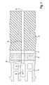
- the FIG. 1 shows an anchoring ground 1, consisting of hollow bricks, on which an old plaster layer 2 is applied.
- the anchoring ground 1 forms a wall of a building, not shown.
- an insulation board 3 is arranged on the old plaster layer 2, which is glued with an adhesive layer 4 on the old plaster layer 2.
- a through hole 5 was made through the insulation board 4, the adhesive layer 3 and the old plaster layer 2 and a borehole 6 in the anchoring ground 1.
- the through hole 5 and the borehole 6 extend axially along a longitudinal axis L, wherein the borehole 6 lies in the direction of insertion E in front of the throughbore 5.
- FIG. 2 is the arrangement of FIG. 1 shown with an insulating anchor 7, which has been introduced into the through hole 5 and the borehole 6.
- the insulating dowel 7 has a spreading section 8, with which the insulating dowel 7 can be anchored in the anchoring ground 1.
- the insulating anchor 7 has in the insertion direction E behind the expansion section 8 a sleeve-like shaft portion 9 with a lattice-like compression zone 10, at the rear end of a holding portion 11 is rotatably disposed with an insulating thread 12.
- the insulating dowel 1 has been introduced so far into the through hole 5 and the borehole 6 until a stop element 13 rests against the adhesive layer 4, which signals the user that the spreading section 8 has been introduced sufficiently far into the borehole 6.
- the stop element 13 is designed as a wing-like, radially projecting stop shoulder, with a material weakening 14 in the form of a quarter circle (see. FIG. 3 ).
- a material weakening 14 in the form of a quarter circle (see. FIG. 3 ).
- the wall thickness of the stop element 13 is reduced in such a way that this area of the stop element 13 only forms a thin spray skin 15.
- the remaining area of the stop element 13 forms a support foot 16, which supports the stop element 13 on the adhesive layer 4. Since the spray skin 15 acts as a drawstring, it prevents the support leg 16 from buckling when the stop shoulder 13 strikes the adhesive layer 4 after the spreading section 8 has been introduced into the borehole 6.
- the holding portion 11 has a receptacle for a tool 17, with which the holding portion 11 can be rotated in the circumferential direction U, so that the insulation thread 12 cuts into the insulation board 3.
- an expansion element 18 is also arranged in the form of a screw, which projects from the holding portion 11 in the insertion direction E through the compression zone 10 through into the expansion section 8.
- the expansion element 8 moves when cutting the insulation material thread 12 in the insulation board 3 with the holding portion 11 in the direction of insertion E, causing the expansion element 18 driven into the expansion section 8, the expansion section 8 radially spreads and the insulation dowel 7 is anchored in the anchoring ground 1.
- the compression zone 10 is compressed in the axial direction, so that it forms a short, closed sleeve in the compressed state, as in FIG. 4 you can see.
- FIG. 4 shows the insulation plug 7 after setting.
- the user now uses the tool 17 to apply an axial compressive force D as a test load in the direction of the longitudinal axis L onto the expansion element 18.
- the acting as a test load axial compressive force D is greater than axial Durck mechanism that were applied to the insulation dowels 7 in the above-described mounting of the insulating dowel 7. Since the in FIG.
- insulation anchor 7 is anchored on schedule in the anchoring ground 1, the pressure force is transmitted from the expansion element 18 on the spread spreader 8 and the wall of the borehole 6 on the anchoring ground 1 without the spreading of the insulation 8 8 dowel with the expansion element 18 noticeable to the user moved in the axial direction, ie in the direction of the longitudinal axis L, to the anchoring ground 1 out.
- the user thus receives the feedback that the insulation dowel 7 is anchored as planned in the anchoring ground 1.
- FIG. 5 illustrated a situation in which the insulation dowel 7 can not be anchored as planned in the anchoring ground 1, since the borehole 6 is greatly expanded radially in the region of the wellbore mouth by chipping 19.
- the insulation dowel 1 is set and mounted according to plan, a transfer of forces from the spread spreader 8 on the wall of the borehole 6 but is not possible because due to the spalling 19 no frictional engagement between the wall of the borehole 6 and the expansion 8 of the insulating anchor 7 possible is.
- the applied by the user via the tool 17 on the insulation dowel 7 axial pressure force D is thus absorbed by the stop element 13, wherein the support leg 16 due to the pressure acting as a test load D radially outwardly kinks, causing the stabilizing spray skin 15 breaks, so that the insulation dowel 7 is considerably moved axially in the direction of the insertion direction E.
- the stop element 13 is axially by the application of the compressive force D, when the insulation plug 7 is moved by the pressure force D in the axial direction. The user thus receives the feedback that the insulation dowel 7 is not anchored as planned in the anchoring ground 1.
Landscapes
- Engineering & Computer Science (AREA)
- General Engineering & Computer Science (AREA)
- Mechanical Engineering (AREA)
- Piles And Underground Anchors (AREA)
- Joining Of Building Structures In Genera (AREA)
Abstract
Description
- Die Erfindung betrifft ein Verfahren zum Befestigen einer Dämmstoffplatte an einem Verankerungsgrund mit den Merkmalen des Oberbegriffs des Anspruchs 1.
- Ein derartiges Verfahren ist aus der Offenlegungsschrift
DE 10 2009 006 769 A1 bekannt. Die Offenlegungsschrift zeigt das Befestigen einer Dämmstoffplatte an einem Verankerungsgrund mit einem Dämmstoffdübel. Bei der Dämmstoffplatte handelt es sich beispielsweise um eine Platte aus extrudiertem Polystyrol, die an einer Betonwand eines Gebäudes zu befestigen ist, wobei die Betonwand den Verankerungsgrund darstellt. Der Dämmstoffdübel ist mit einem als wendelförmiges Dämmstoffgewinde ausgeführten Halteabschnitt ausgestaltet, der beim Einbringen in die Dämmstoffplatte einen Gewindegang in den Dämmstoff schneidet. Zudem weist der Dämmstoffdübel einen Spreizabschnitt auf, der durch das Eintreiben einer Schraube radial aufgespreizt und in einem Bohrloch verspannt werden kann. Zum Befestigen der Dämmstoffplatte wird durch die Dämmstoffplatte hindurch in dem Verankerungsgrund ein Bohrloch erstellt. In die dabei in der Dämmstoffplatte entstandene Durchgangsbohrung wird der Dämmstoffdübel eingebracht, so weit, bis der Spreizabschnitt im Bohrloch liegt. Beim Einbringen wird mit dem Dämmstoffgewinde ein Gewindegang in die Dämmstoffplatte geschnitten. Sobald der Spreizbereich des Dämmstoffdübels vollständig im Bohrloch liegt, wird die Schraube in den Spreizbereich eingetrieben, wodurch dieser radial aufgespreizt und gegen die Wand des Bohrlochs gepresst und verankert wird, so dass Kräfte vom planmäßig gesetzten Dämmstoffdübel in den Verankerungsgrund eingetragen werden können. Insbesondere dann, wenn der Verankerungsgrund aus einem relativ weichen und/oder einem Baustoff mit Hohlkammern besteht, kann es vorkommen, dass es im Bereich des Bohrlochmunds zu Abplatzungen kommt, so dass das Bohrloch in diesem Bereich einen zu großen Durchmesser aufweist. Der Spreizbereich des Dämmstoffdübels kann in einem derartigen Bohrloch zwar aufgespreizt werden, weshalb ein Anwender meint, dass der Dämmstoffdübel planmäßig verankert sei, axiale Kräfte können aber nicht in ausreichender Größe zwischen Bohrlochwand und Spreizbereich übertragen werden. - Aufgabe der Erfindung ist daher, ein Verfahren zum Befestigen einer Dämmstoffplatte vorzuschlagen, mit dem auf einfache Weise festgestellt werden kann, ob der Dämmstoffdübel planmäßig verankert ist.
- Diese Aufgabe wird erfindungsgemäß durch ein Verfahren mit den Merkmalen des Anspruchs 1 gelöst. Mit dem erfindungsgemäßen Verfahren wird eine Dämmstoffplatte mittels eines Dämmstoffdübels an einem Verankerungsgrund befestigt. Der Verankerungsgrund ist beispielsweise eine Wand eines Gebäudes, an der die Dämmstoffplatte für ein Wärmedämmverbundsystem zu befestigen ist. Bei der Dämmstoffplatte handelt es sich insbesondere um eine Platte aus extrudiertem Polystyrol, wobei die Erfindung nicht auf diesen Dämmstoff beschränkt ist. Grundsätzlich kann das erfindungsgemäße Verfahren auch mit Holzfaserdämmplatten, Stein- oder Glaswollplatten und weiteren Dämmstoffen durchgeführt werden. Der im Verfahren verwendete Dämmstoffdübel weist einen Spreizabschnitt auf, mit dem der Dämmstoffdübel in einem Bohrloch im Verankerungsgrund verankert werden kann. Zum Verankern wird in den Spreizabschnitt ein Spreizelement eingetrieben, wobei das Spreizelement insbesondere eine Schraube ist. Zudem umfasst der Dämmstoffdübel einen Halteabschnitt zum Halten der Dämmstoffplatte. Der Halteabschnitt kann beispielsweise als ebener Dämmstoffteller ausgeführt sein. Weitere Ausgestaltungsformen sind ebenso möglich, sofern sie geeignet sind, die Dämmstoffplatte zu halten. Das erfindungsgemäße Verfahren umfasst folgende Schritte:
- 1.) Bohren eines Bohrlochs in den Verankerungsgrund;
- 2.) Einbringen des Spreizabschnitts in das Bohrloch; und
- 3.) Eintreiben eines Spreizelements in den Spreizabschnitt, wodurch der Spreizabschnitt verspreizt und der Dämmstoffdübel im Verankerungsgrund verankert wird, wobei der Halteabschnitt an oder in der Dämmstoffplatte liegt.
- Durch diese Schritte wird der Dämmstoffdübel gesetzt, wobei die Schritte 2 und 3 nacheinander oder gleichzeitig erfolgen können. Nachdem der Setzvorgang mit dem Verfahrensschritt 3 abgeschlossen und der Spreizabschnitt planmäßig verspreizt und verankert ist, wird erfindungsgemäß zudem folgender Verfahrensschritt durchgeführt:
- 4.) Aufbringen einer äußeren axialen Druckkraft als Prüflast auf den gesetzten Dämmstoffdübel, insbesondere auf das Spreizelement, derart, dass die Druckkraft bei planmäßiger Verankerung des Dämmstoffdübels im Verankerungsgrund vom Spreizabschnitt auf dem Verankerungsgrund übertragen wird, im Wesentlichen ohne dass sich der Spreizabschnitt mit dem Spreizelement in axialer Richtung bewegt.
- Mit "axial" ist die Längsrichtung des Dämmstoffdübels gemeint, die insbesondere der Einbringrichtung entspricht, in der der Dämmstoffdübel in das Bohrloch eingebracht wird. Die im Verfahrensschritt 4 als Prüflast aufgebrachte axiale Druckkraft ist dabei insbesondere größer, als die durch den Anwender in den vorangegangenen Verfahrensschritten 2 und 3 bei der Montage des Dämmstoffdübels, also beim Einbringen des Spreizabschnitts und beim Eintreiben des Spreizelements aufgebrachten Druckkräfte, die in axialer Richtung wirken. Insbesondere wird der Dämmstoffdübel nach Abschluss des Setzvorgangs zunächst bewusst entlastet, das heißt, der Anwender übt nur eine geringe, insbesondere keine axial wirkende Druckkraft auf den Dämmstoffdübel aus. Erst nach dem Entlasten wird vom Anwender bewusst der Verfahrensschritt 4 durchgeführt und die axiale Druckkraft auf den gesetzten Dämmstoffdübel aufgebracht.
- Wenn der Dämmstoffdübel planmäßig im Verankerungsgrund verankert ist, so wird die im Verfahrensschritt 4 auf den Dämmstoffdübel ausgeübte axiale Druckkraft über den gegen die Bohrlochwand gepressten Spreizabschnitt in den Verankerungsgrund übertragen, wobei sich der Dämmstoffdübel dabei in axialer Richtung im Wesentlichen nicht bewegt. "Im Wesentlichen" bedeutet hier, dass außer einer elastischen Stauchung des Materials des Dübels keine zusätzliche Bewegung des Dämmstoffdübels in Einbringrichtung erfolgt. Insbesondere wird die axiale Druckkraft direkt auf das Spreizelement aufgebracht und über das Spreizelement auf den Spreizabschnitt übertragen. Falls eine Kraftübertragung zwischen dem radial aufgespreizten Spreizabschnitt und der Bohrlochwand nicht planmäßig möglich ist, so bewegt sich der Dämmstoffdübel unter der Wirkung der axialen Druckkraft in Einbringrichtung zum Verankerungsgrund hin, was der Anwender bemerkt. Dabei wird der Spreizabschnitt mit dem Spreizelement in axialer Richtung bewegt, wobei der Dämmstoff gestaucht werden kann. Hierdurch wird dem Anwender signalisiert, dass der Spreizbereich nicht planmäßig verankert ist und dass axial wirkende Kräfte nicht in ausreichender Größe auf den Verankerungsgrund übertragen werden können. Durch das erfindungsgemäße Verfahren ist es dem Anwender auf einfache Art und Weise möglich zu prüfen, ob der Dämmstoffdübel planmäßig verankert ist oder nicht.
- Vorzugsweise wird die axiale Druckkraft im Verfahrensschritt 4 mittels eines Werkzeugs, das zum Eintreiben des Spreizelements verwendet wird, auf den Dämmstoffdübel aufgebracht, insbesondere unmittelbar auf das Spreizelement. Beispielsweise handelt es sich bei dem Werkzeug um einen Bit eines Akkuschraubers, der in eine Aufnahme eingreift, um ein als Schraube ausgebildetes Spreizelement einzuschrauben. Zum Durchführen des Verfahrensschritts 4 muss der Anwender somit kein spezielles Werkzeug verwenden und einen Wechsel des Werkzeugs durchführen, so dass der Verfahrensschritt 4 zeitnah auf die Verfahrensschritte 1 bis 3 folgen kann.
- Weiterhin ist bevorzugt, dass der Dämmstoffdübel ein Anschlagelement zur Anlage am Verankerungsgrund oder einer festen Zwischenschicht zwischen dem Verankerungsgrund und der Dämmstoffplatte aufweist. Die Zwischenschicht kann beispielsweise eine mineralische Kleberschicht sein, mit der die Dämmstoffplatte mit dem Verankerungsgrund verklebt wurde. Das Anschlagelement signalisiert beispielsweise dem Anwender im Verfahrensschritt 2, dass der Spreizabschnitt ausreichend weit in das Bohrloch eingeführt ist. Dies ist beispielsweise der Fall, wenn das Anschlagelement auf den Verankerungsgrund oder die Zwischenschicht trifft. Dann wird das Einbringen gestoppt, da das Anschlagelement am Verankerungsgrund beziehungsweise der Zwischenschicht ansteht. Um den Verfahrensschritt 4 zu ermöglichen, ist das Anschlagelement derart gestaltet, dass es durch das Aufbringen der axialen Druckkraft axial nachgibt, wenn der Dämmstoffdübel durch die Druckkraft in axialer Richtung bewegt wird, was der Fall ist, wenn der Spreizabschnitt nicht ausreichend im Verankerungsgrund verankert ist. Dabei ist die axiale Druckkraft, bei der das Anschlagelement nachgibt, geringer als die axiale Druckkraft, die als Prüflast auf den Dämmstoffdübel aufgebracht wird. Durch das Nachgeben wird verhindert, dass die als Prüflast wirkende axiale Druckkraft vom Anschlagelement auf den Verankerungsgrund oder die Zwischenschicht übertragen wird, was beim Anwender fälschlicherweise den Eindruck erwecken würde, dass der Dämmstoffdübel planmäßig verankert ist.
- Vorzugsweise weist das Anschlagelement eine Materialschwächung auf, um die axiale Nachgiebigkeit zu erreichen. Vorzugsweise ist das Anschlagelement aufgrund der Materialschwächung derart gestaltet, dass das Anschlagelement durch die Druckkraft gestaucht wird und/oder knickt. Insbesondere ist das Anschlagelement als Knickelement ausgestaltet, das über eine Spritzhaut, die die Materialschwächung darstellt, mit einem Schaftbereich des Dämmstoffdübels verbunden ist. Die Spritzhaut stabilisiert das Knickelement derart, dass es seine Funktion als Anschlag erfüllen kann und nicht schon dann ausknickt, wenn es beim Einbringen des Dämmstoffdübels auf den Verankerungsgrund trifft. Wird nach dem Setzen des Dämmstoffdübels eine bestimmte axiale Druckkraft überschritten, so reißt die Spritzhaut und das Knickelement wird instabil und knickt aus. Dies ist dann der Fall, wenn die im Verfahrenschritt 4 auf den Dämmstoffdübel aufgebrachte axiale Druckkraft nicht vom verspreizten Spreizbereich auf den Verankerungsgrund übertragen werden kann und der Dämmstoffdübel sich somit unter Wirkung der Druckkraft axial in Einbringrichtung bewegt.
- Weiterhin ist bevorzugt, dass der Halteabschnitt ein Dämmstoffgewinde zum Einschrauben in die Dämmstoffplatte aufweist, so dass das Halteelement in die Dämmstoffplatte versenkt werden kann, wodurch eine Wärmebrücke vermieden wird.
- Vorzugsweise erfolgt das Einschrauben des Dämmstoffgewindes gleichzeitig mit dem Eintreiben des Spreizelements, so dass eine schnelle und wirtschaftliche Montage möglich ist.
- Das erfindungsgemäße Verfahren wird nachfolgend anhand von zwei in den Figuren dargestellten Ausführungsbeispielen näher erläutert.
- Es zeigen:
- Figur 1
- eine an einem Verankerungsgrund angebrachte Dämmstoffplatte nach dem Bohren eines Bohrlochs in einer Seitenansicht;
- Figur 2
- einen in das Bohrloch eingebrachten Dämmstoffdübel in einer Seitenansicht;
- Figur 3
- ein Anschlagelement des Dämmstoffdübels aus
Figur 2 in einer Detaildarstellung; - Figur 4
- den Dämmstoffdübel nach dem Setzen beim Aufbringen einer axialen Druckkraft in einer Seitenansicht;
- Figur 5
- eine Anordnung wie in
Figur 3 , wobei das Bohrloch Abplatzungen aufweist; und - Figur 6
- ein Anschlagelement des Dämmstoffdübels aus
Figur 5 in einer Detaildarstellung. - Die
Figur 1 zeigt einen Verankerungsgrund 1, bestehend aus Hochlochziegeln, auf dem eine Altputzschicht 2 aufgebracht ist. Der Verankerungsgrund 1 bildet eine Wand eines nicht näher dargestellten Gebäudes. Zur Verbesserung der Wärmedämmung des Gebäudes ist auf der Altputzschicht 2 eine Dämmstoffplatte 3 angeordnet, die mit einer Kleberschicht 4 auf die Altputzschicht 2 geklebt ist. Um die Dämmstoffplatte 3 zusätzlich mechanisch mit dem Verankerungsgrund 1 verbinden zu können, wurde eine Durchgangsbohrung 5 durch die Dämmstoffplatte 4, die Kleberschicht 3 und die Altputzschicht 2 hindurch und ein Bohrloch 6 im Verankerungsgrund 1 erstellt. Die Durchgangsbohrung 5 und das Bohrloch 6 erstrecken sich axial entlang einer Längsachse L, wobei das Bohrloch 6 in Einbringrichtung E vor der Durchgangsbohrung 5 liegt. - In
Figur 2 ist die Anordnung derFigur 1 mit einem Dämmstoffdübel 7 dargestellt, der in die Durchgangsbohrung 5 und das Bohrloch 6 eingebracht worden ist. Der Dämmstoffdübel 7 weist einen Spreizabschnitt 8 auf, mit dem der Dämmstoffdübel 7 im Verankerungsgrund 1 verankert werden kann. Der Dämmstoffdübel 7 weist in Einbringrichtung E hinter dem Spreizabschnitt 8 einen hülsenartigen Schaftabschnitt 9 mit einer gitterartigen Stauchzone 10 auf, an dessen hinterem Ende ein Halteabschnitt 11 mit einem Dämmstoffgewinde 12 drehbar angeordnet ist. Der Dämmstoffdübel 1 ist so weit in die Durchgangsbohrung 5 und das Bohrloch 6 eingebracht worden, bis ein Anschlagelement 13 an der Kleberschicht 4 anliegt, was dem Anwender signalisiert, dass der Spreizabschnitt 8 ausreichend weit in das Bohrloch 6 eingebracht wurde. Das Anschlagelement 13 ist als flügelartig, radial abstehende Anschlagschulter ausgeführt, mit einer Materialschwächung 14 in Form eines Viertelkreises (vgl.Figur 3 ). Im Bereich der Materialschwächung 14 ist die Wandstärke des Anschlagelements 13 derart reduziert, dass dieser Bereich des Anschlagelements 13 nur noch eine dünne Spritzhaut 15 bildet. Der übrige Bereich des Anschlagelements 13 bildet einen Stützfuß 16, der das Anschlagelement 13 an der Kleberschicht 4 abstützt. Da die Spritzhaut 15 als Zugband wirkt, verhindert sie, dass der Stützfuß 16 ausknickt, wenn die Anschlagschulter 13 nach dem Einbringen des Spreizabschnitts 8 in das Bohrloch 6 auf die Kleberschicht 4 trifft. - Der Halteabschnitt 11 weist eine Aufnahme für ein Werkzeug 17 auf, mit dem der Halteabschnitt 11 in Umfangsrichtung U gedreht werden kann, so dass das Dämmstoffgewinde 12 in die Dämmstoffplatte 3 schneidet. Am Halteabschnitt 11 ist zudem ein Spreizelement 18 in Form einer Schraube angeordnet, das vom Halteabschnitt 11 aus in Einbringrichtung E durch die Stauchzone 10 hindurch bis in den Spreizabschnitt 8 ragt. Das Spreizelement 8 bewegt sich beim Einschneiden des Dämmstoffgewindes 12 in die Dämmstoffplatte 3 mit dem Halteabschnitt 11 in Richtung der Einbringrichtung E, wodurch das Spreizelement 18 in den Spreizabschnitt 8 eingetrieben, der Spreizabschnitt 8 radial verspreizt und der Dämmstoffdübel 7 im Verankerungsgrund 1 verankert wird. Hierbei wird die Stauchzone 10 in axialer Richtung gestaucht, so dass sie im gestauchten Zustand eine kurze, geschlossene Hülse bildet, wie dies in
Figur 4 zu sehen ist. -
Figur 4 zeigt den Dämmstoffdübel 7 nach dem Setzen. Zum Überprüfen, ob der Dämmstoffdübel 7 fest im Verankerungsgrund 1 verankert ist, wird nun vom Anwender mit dem Werkzeug 17 eine axiale Druckkraft D als Prüflast in Richtung der Längsachse L auf das Spreizelement 18 aufgebracht. Die als Prüflast wirkende axiale Druckkraft D ist dabei größer als axiale Durckkräfte, die bei der zuvor beschriebenen Montage des Dämmstoffdübels 7 auf den Dämmstoffdübel 7 aufgebracht wurden. Da der inFigur 4 dargestellte Dämmstoffdübel 7 planmäßig im Verankerungsgrund 1 verankert ist, wird die Druckkraft vom Spreizelement 18 über den verspreizten Spreizabschnitt 8 und die Wand des Bohrlochs 6 auf den Verankerungsgrund 1 übertragen, ohne dass der Spreizabschnitt 8 des Dämmstoffdübels 7 mit dem Spreizelement 18 sich für den Anwender bemerkbar in axialer Richtung, also in Richtung der Längsachse L, zum Verankerungsgrund 1 hin bewegt. Der Anwender bekommt somit die Rückmeldung, dass der Dämmstoffdübel 7 planmäßig im Verankerungsgrund 1 verankert ist. - Dagegen ist in
Figur 5 eine Situation dargestellt, in der der Dämmstoffdübel 7 nicht planmäßig im Verankerungsgrund 1 verankert werden kann, da das Bohrloch 6 im Bereich des Bohrlochmundes durch Abplatzungen 19 stark radial geweitet ist. Der Dämmstoffdübel 1 ist zwar planmäßig gesetzt und montiert, eine Übertragung von Kräften vom gespreizten Spreizabschnitt 8 auf die Wand des Bohrlochs 6 ist aber nicht möglich, da aufgrund der Abplatzungen 19 kein Reibschluss zwischen der Wand des Bohrlochs 6 und dem Spreizabschnitt 8 des Dämmstoffdübels 7 möglich ist. Die vom Anwender über das Werkzeug 17 auf den Dämmstoffdübel 7 aufgebrachte axiale Druckkraft D wird somit vom Anschlagelement 13 aufgenommen, wobei der Stützfuß 16 auf Grund der als Prüflast wirkenden Druckkraft D radial nach außen knickt, wodurch die stabilisierende Spritzhaut 15 reißt, so dass der Dämmstoffdübel 7 merklich axial in Richtung der Einbringrichtung E bewegt wird. Das Anschlagelement 13 gibt durch das Aufbringen der Druckkraft D axial nach, wenn der Dämmstoffdübel 7 durch die Druckkraft D in axialer Richtung bewegt wird. Der Anwender bekommt somit die Rückmeldung, dass der Dämmstoffdübel 7 nicht planmäßig im Verankerungsgrund 1 verankert ist. Obwohl nach dem Knicken des Stützfußes 16 eine axiale Bewegung des Dämmstoffdübels 7 möglich ist, verhindert das Anschlagelement 13, dass der Dämmstoffdübel 7 so weit in die Dämmstoffplatte 3 eindringt, dass das Dämmstoffgewinde 12 des Halteelements 11 die Dämmstoffplatte 3 beschädigt.Bezugszeichenliste Verfahren zum Befestigen einer Dämmstoffplatte an einem Verankerungsgrund 1 Verankerungsgrund 2 Altputzschicht 3 Dämmstoffplatte 4 Kleberschicht 5 Durchgangsbohrung 6 Bohrloch 7 Dämmstoffdübel 8 Spreizabschnitt 9 Schaftabschnitt 10 Stauchzone 11 Halteabschnitt 12 Dämmstoffgewinde 13 Anschlagelement 14 Materialschwächung 15 Spritzhaut 16 Stützfuß 17 Werkzeug 18 Spreizelement 19 Abplatzung D axiale Druckkraft E Einbringrichtung L Längsachse U Umfangsrichtung
Claims (8)
- Verfahren zum Befestigen einer Dämmstoffplatte (3) an einem Verankerungsgrund (1) mit einem Dämmstoffdübel (7), der einen Spreizabschnitt (8) zum Verankern des Dämmstoffdübels (7) im Verankerungsgrund (1) und einen Halteabschnitt (11) zum Halten der Dämmstoffplatte (3) aufweist,
wobei das Verfahren folgende Schritte umfasst:1.) Bohren eines Bohrlochs (6) in den Verankerungsgrund (1);2.) Einbringen des Spreizabschnitts (8) in das Bohrloch (6), und3.) Eintreiben eines Spreizelements (18) in den Spreizabschnitt (8), wodurch der Spreizabschnitt (8) verspreizt und der Dämmstoffdübel (7) im Verankerungsgrund (1) verankert wird, wobei der Halteabschnitt (11) an oder in der Dämmstoffplatte (3) liegt;gekennzeichnet durch den nachfolgenden Schritt:4.) Aufbringen einer äußeren axialen Druckkraft (D) als Prüflast auf den gesetzten Dämmstoffdübel (7), derart, dass die Druckkraft (D) bei planmäßiger Verankerung des Dämmstoffdübels (7) im Verankerungsgrund (1) vom Spreizabschnitt (8) auf den Verankerungsgrund (1) übertragen wird, im Wesentlichen ohne dass sich der Spreizabschnitt (8) mit dem Spreizelement in axialer Richtung bewegt. - Verfahren nach Anspruch 1, dadurch gekennzeichnet, dass die Druckkraft (D) mittels eines Werkzeugs (17), das zum Eintreiben des Spreizelements (18) verwendet wird, auf den Dämmstoffdübel (7) aufgebracht wird.
- Verfahren nach Anspruch 1 oder 2, dadurch gekennzeichnet, dass die Druckkraft (D) unmittelbar auf das Spreizelement (18) aufgebracht wird.
- Verfahren nach einem der Ansprüche 1 bis 3, dadurch gekennzeichnet, dass der Dämmstoffdübel (7) ein Anschlagelement (13) zur Anlage am Verankerungsgrund (1) aufweist, das durch Aufbringen der Druckkraft (D) axial nachgibt, wenn der Dämmstoffdübel (7) durch die Druckkraft (D) in axialer Richtung bewegt wird.
- Verfahren nach Anspruch 4, dadurch gekennzeichnet, dass das Anschlagelement (13) eine Materialschwächung (14) aufweist.
- Verfahren nach Anspruch 4 oder 5, dadurch gekennzeichnet, dass das Anschlagelement (13) durch die Druckkraft (D) gestaucht wird und/oder knickt.
- Verfahren nach einem der Ansprüche 1 bis 6, dadurch gekennzeichnet, dass der Halteabschnitt (11) ein Dämmstoffgewinde (12) zum Einschrauben in die Dämmstoffplatte (3) ist.
- Verfahren nach Anspruch 7, dadurch gekennzeichnet, dass das Einschrauben des Dämmstoffgewindes (12) gleichzeitig mit dem Eintreiben des Spreizelements (18) erfolgt.
Applications Claiming Priority (2)
| Application Number | Priority Date | Filing Date | Title |
|---|---|---|---|
| DE102012103909 | 2012-05-04 | ||
| DE201310102845 DE102013102845A1 (de) | 2012-05-04 | 2013-03-20 | Verfahren zum Befestigen einer Dämmstoffplatte an einem Verankerungsgrund |
Publications (2)
| Publication Number | Publication Date |
|---|---|
| EP2660404A2 true EP2660404A2 (de) | 2013-11-06 |
| EP2660404A3 EP2660404A3 (de) | 2014-06-04 |
Family
ID=48430641
Family Applications (1)
| Application Number | Title | Priority Date | Filing Date |
|---|---|---|---|
| EP13401046.1A Withdrawn EP2660404A3 (de) | 2012-05-04 | 2013-05-02 | Verfahren zum Befestigen einer Dämmstoffplatte an einem Verankerungsgrund |
Country Status (3)
| Country | Link |
|---|---|
| EP (1) | EP2660404A3 (de) |
| DE (1) | DE102013102845A1 (de) |
| RU (1) | RU2013120188A (de) |
Cited By (1)
| Publication number | Priority date | Publication date | Assignee | Title |
|---|---|---|---|---|
| CN111155705A (zh) * | 2020-01-16 | 2020-05-15 | 无锡北大建筑工程有限公司 | 一种复合式外墙板用环保节能型连接件及其生产方法 |
Citations (1)
| Publication number | Priority date | Publication date | Assignee | Title |
|---|---|---|---|---|
| DE102009006769A1 (de) | 2009-01-30 | 2010-08-05 | Fischerwerke Gmbh & Co. Kg | Dämmstoffhalter |
-
2013
- 2013-03-20 DE DE201310102845 patent/DE102013102845A1/de not_active Withdrawn
- 2013-04-30 RU RU2013120188/03A patent/RU2013120188A/ru not_active Application Discontinuation
- 2013-05-02 EP EP13401046.1A patent/EP2660404A3/de not_active Withdrawn
Patent Citations (1)
| Publication number | Priority date | Publication date | Assignee | Title |
|---|---|---|---|---|
| DE102009006769A1 (de) | 2009-01-30 | 2010-08-05 | Fischerwerke Gmbh & Co. Kg | Dämmstoffhalter |
Cited By (1)
| Publication number | Priority date | Publication date | Assignee | Title |
|---|---|---|---|---|
| CN111155705A (zh) * | 2020-01-16 | 2020-05-15 | 无锡北大建筑工程有限公司 | 一种复合式外墙板用环保节能型连接件及其生产方法 |
Also Published As
| Publication number | Publication date |
|---|---|
| RU2013120188A (ru) | 2014-11-10 |
| DE102013102845A1 (de) | 2013-11-07 |
| EP2660404A3 (de) | 2014-06-04 |
Similar Documents
| Publication | Publication Date | Title |
|---|---|---|
| EP2752533B1 (de) | Vorrichtung zum Eintreiben eines Spreizelements in einen Dübel. | |
| DE10041299B4 (de) | Befestigungssystem | |
| EP1134435B1 (de) | Dübel | |
| EP2049745B1 (de) | Befestigungssystem aus dübel und kunststoffnagel sowie verfahren zur montage von dämmstoffplatten | |
| EP1978177B1 (de) | Abstandshalter zur Befestigung eines Halteelementes in einer Wandung | |
| EP2666919B1 (de) | Verfahren und Befestigungssystem zum Anbringen von Dämmstoffplatten an einem Untergrund | |
| EP2044270B1 (de) | Befestigungssysteme und verfahren zur montage von dämmstoffplatten | |
| DE102008048672B3 (de) | Werkzeug mit einer Vorschubbewegungs-Übertragungseinrichtung | |
| EP2923011B1 (de) | Kombination mit einem anker für plattenförmige bauteile sowie befestigungsanordnung | |
| EP0564889A1 (de) | Verbindungseinrichtung für ein insbesondere rohrförmiges Bauteil | |
| EP2672129A2 (de) | Anker für Wände, zum Befestigen von abragenden Bauwerken wie Markisen | |
| DE102011102825B4 (de) | Verbindungsanordnung und Verfahren zur Herstellung einer Durchstanzsicherung | |
| DE4210488A1 (de) | Verbindungseinrichtung für ein insbesondere rohrförmiges Bauteil | |
| EP3214321B1 (de) | Anordnung mit einer leichtbauplatte und einem dübel sowie verfahren zum einsetzen eines dübels in eine leichtbauplatte | |
| DE10114929C2 (de) | Abstandshalter für nicht-tragfähige Vorsatzschalen und Verfahren zur Befestigung | |
| DE102013102845A1 (de) | Verfahren zum Befestigen einer Dämmstoffplatte an einem Verankerungsgrund | |
| AT511443B1 (de) | Einrichtung zur befestigung einer last | |
| EP1867805A2 (de) | Verfahren und Vorrichtung zur Montage von Bauteilen, insbesondere Dämmstoffplatten, an einer Wand | |
| DE102018008598A1 (de) | Abstandshalter und Befestiger für durch eine Fassade hindurch am Gebäude zu befestigenden Teile | |
| EP2740851A1 (de) | Spreizelement mit Abdeckscheibe | |
| AT402335B (de) | Justierdübelsystem zur einstellbaren verbindung zweier elemente miteinander sowie eine gewindehülse, eine verankerungshülse, ein verankerungselement und eine bohrhilfe für das justierdübelsystem | |
| EP1417418A1 (de) | Isolierplattendübel | |
| EP3702629A9 (de) | Universelles montageset zum montieren eines rahmens an einem untergrund | |
| EP3354812A1 (de) | System zur befestigung einer dämmplatte | |
| EP3470589A1 (de) | Verfahren zum befestigen eines dämmstoffelements und dämmstoffdübel |
Legal Events
| Date | Code | Title | Description |
|---|---|---|---|
| PUAI | Public reference made under article 153(3) epc to a published international application that has entered the european phase |
Free format text: ORIGINAL CODE: 0009012 |
|
| AK | Designated contracting states |
Kind code of ref document: A2 Designated state(s): AL AT BE BG CH CY CZ DE DK EE ES FI FR GB GR HR HU IE IS IT LI LT LU LV MC MK MT NL NO PL PT RO RS SE SI SK SM TR |
|
| AX | Request for extension of the european patent |
Extension state: BA ME |
|
| PUAL | Search report despatched |
Free format text: ORIGINAL CODE: 0009013 |
|
| AK | Designated contracting states |
Kind code of ref document: A3 Designated state(s): AL AT BE BG CH CY CZ DE DK EE ES FI FR GB GR HR HU IE IS IT LI LT LU LV MC MK MT NL NO PL PT RO RS SE SI SK SM TR |
|
| AX | Request for extension of the european patent |
Extension state: BA ME |
|
| RIC1 | Information provided on ipc code assigned before grant |
Ipc: F16B 13/00 20060101ALI20140428BHEP Ipc: F16B 13/12 20060101ALI20140428BHEP Ipc: E04B 1/76 20060101AFI20140428BHEP |
|
| RAP1 | Party data changed (applicant data changed or rights of an application transferred) |
Owner name: FISCHERWERKE GMBH & CO. KG |
|
| 17P | Request for examination filed |
Effective date: 20141117 |
|
| RBV | Designated contracting states (corrected) |
Designated state(s): AL AT BE BG CH CY CZ DE DK EE ES FI FR GB GR HR HU IE IS IT LI LT LU LV MC MK MT NL NO PL PT RO RS SE SI SK SM TR |
|
| 17Q | First examination report despatched |
Effective date: 20150414 |
|
| STAA | Information on the status of an ep patent application or granted ep patent |
Free format text: STATUS: THE APPLICATION IS DEEMED TO BE WITHDRAWN |
|
| 18D | Application deemed to be withdrawn |
Effective date: 20150825 |