EP2660095A2 - Wandlerstufe, Stromrichter, der eine solche Wandlerstufe umfasst, Gleichrichter, der einen solchen Stromrichter umfasst, und Batterieladeanordnung, die einen solchen Stromrichter oder eine solche Wandlerstufe umfasst - Google Patents
Wandlerstufe, Stromrichter, der eine solche Wandlerstufe umfasst, Gleichrichter, der einen solchen Stromrichter umfasst, und Batterieladeanordnung, die einen solchen Stromrichter oder eine solche Wandlerstufe umfasst Download PDFInfo
- Publication number
- EP2660095A2 EP2660095A2 EP13166370.0A EP13166370A EP2660095A2 EP 2660095 A2 EP2660095 A2 EP 2660095A2 EP 13166370 A EP13166370 A EP 13166370A EP 2660095 A2 EP2660095 A2 EP 2660095A2
- Authority
- EP
- European Patent Office
- Prior art keywords
- converter
- conversion
- control law
- conversion stage
- switch
- Prior art date
- Legal status (The legal status is an assumption and is not a legal conclusion. Google has not performed a legal analysis and makes no representation as to the accuracy of the status listed.)
- Granted
Links
- 239000004065 semiconductor Substances 0.000 claims abstract description 44
- 239000003990 capacitor Substances 0.000 claims abstract description 20
- 238000006243 chemical reaction Methods 0.000 claims description 172
- 238000004804 winding Methods 0.000 claims description 15
- 238000010586 diagram Methods 0.000 description 4
- 230000010363 phase shift Effects 0.000 description 4
- 241000287107 Passer Species 0.000 description 3
- 241001080024 Telles Species 0.000 description 2
- 230000000295 complement effect Effects 0.000 description 2
- 230000007423 decrease Effects 0.000 description 2
- 238000001914 filtration Methods 0.000 description 2
- 230000002441 reversible effect Effects 0.000 description 2
- 235000021183 entrée Nutrition 0.000 description 1
- 230000007704 transition Effects 0.000 description 1
Images


Classifications
-
- H—ELECTRICITY
- H02—GENERATION; CONVERSION OR DISTRIBUTION OF ELECTRIC POWER
- H02J—CIRCUIT ARRANGEMENTS OR SYSTEMS FOR SUPPLYING OR DISTRIBUTING ELECTRIC POWER; SYSTEMS FOR STORING ELECTRIC ENERGY
- H02J7/00—Circuit arrangements for charging or depolarising batteries or for supplying loads from batteries
- H02J7/02—Circuit arrangements for charging or depolarising batteries or for supplying loads from batteries for charging batteries from ac mains by converters
-
- B—PERFORMING OPERATIONS; TRANSPORTING
- B60—VEHICLES IN GENERAL
- B60L—PROPULSION OF ELECTRICALLY-PROPELLED VEHICLES; SUPPLYING ELECTRIC POWER FOR AUXILIARY EQUIPMENT OF ELECTRICALLY-PROPELLED VEHICLES; ELECTRODYNAMIC BRAKE SYSTEMS FOR VEHICLES IN GENERAL; MAGNETIC SUSPENSION OR LEVITATION FOR VEHICLES; MONITORING OPERATING VARIABLES OF ELECTRICALLY-PROPELLED VEHICLES; ELECTRIC SAFETY DEVICES FOR ELECTRICALLY-PROPELLED VEHICLES
- B60L53/00—Methods of charging batteries, specially adapted for electric vehicles; Charging stations or on-board charging equipment therefor; Exchange of energy storage elements in electric vehicles
- B60L53/10—Methods of charging batteries, specially adapted for electric vehicles; Charging stations or on-board charging equipment therefor; Exchange of energy storage elements in electric vehicles characterised by the energy transfer between the charging station and the vehicle
- B60L53/14—Conductive energy transfer
-
- B—PERFORMING OPERATIONS; TRANSPORTING
- B60—VEHICLES IN GENERAL
- B60L—PROPULSION OF ELECTRICALLY-PROPELLED VEHICLES; SUPPLYING ELECTRIC POWER FOR AUXILIARY EQUIPMENT OF ELECTRICALLY-PROPELLED VEHICLES; ELECTRODYNAMIC BRAKE SYSTEMS FOR VEHICLES IN GENERAL; MAGNETIC SUSPENSION OR LEVITATION FOR VEHICLES; MONITORING OPERATING VARIABLES OF ELECTRICALLY-PROPELLED VEHICLES; ELECTRIC SAFETY DEVICES FOR ELECTRICALLY-PROPELLED VEHICLES
- B60L53/00—Methods of charging batteries, specially adapted for electric vehicles; Charging stations or on-board charging equipment therefor; Exchange of energy storage elements in electric vehicles
- B60L53/20—Methods of charging batteries, specially adapted for electric vehicles; Charging stations or on-board charging equipment therefor; Exchange of energy storage elements in electric vehicles characterised by converters located in the vehicle
-
- B—PERFORMING OPERATIONS; TRANSPORTING
- B60—VEHICLES IN GENERAL
- B60L—PROPULSION OF ELECTRICALLY-PROPELLED VEHICLES; SUPPLYING ELECTRIC POWER FOR AUXILIARY EQUIPMENT OF ELECTRICALLY-PROPELLED VEHICLES; ELECTRODYNAMIC BRAKE SYSTEMS FOR VEHICLES IN GENERAL; MAGNETIC SUSPENSION OR LEVITATION FOR VEHICLES; MONITORING OPERATING VARIABLES OF ELECTRICALLY-PROPELLED VEHICLES; ELECTRIC SAFETY DEVICES FOR ELECTRICALLY-PROPELLED VEHICLES
- B60L53/00—Methods of charging batteries, specially adapted for electric vehicles; Charging stations or on-board charging equipment therefor; Exchange of energy storage elements in electric vehicles
- B60L53/30—Constructional details of charging stations
- B60L53/31—Charging columns specially adapted for electric vehicles
-
- H—ELECTRICITY
- H02—GENERATION; CONVERSION OR DISTRIBUTION OF ELECTRIC POWER
- H02M—APPARATUS FOR CONVERSION BETWEEN AC AND AC, BETWEEN AC AND DC, OR BETWEEN DC AND DC, AND FOR USE WITH MAINS OR SIMILAR POWER SUPPLY SYSTEMS; CONVERSION OF DC OR AC INPUT POWER INTO SURGE OUTPUT POWER; CONTROL OR REGULATION THEREOF
- H02M3/00—Conversion of dc power input into dc power output
- H02M3/22—Conversion of dc power input into dc power output with intermediate conversion into ac
- H02M3/24—Conversion of dc power input into dc power output with intermediate conversion into ac by static converters
- H02M3/28—Conversion of dc power input into dc power output with intermediate conversion into ac by static converters using discharge tubes with control electrode or semiconductor devices with control electrode to produce the intermediate ac
- H02M3/325—Conversion of dc power input into dc power output with intermediate conversion into ac by static converters using discharge tubes with control electrode or semiconductor devices with control electrode to produce the intermediate ac using devices of a triode or a transistor type requiring continuous application of a control signal
- H02M3/335—Conversion of dc power input into dc power output with intermediate conversion into ac by static converters using discharge tubes with control electrode or semiconductor devices with control electrode to produce the intermediate ac using devices of a triode or a transistor type requiring continuous application of a control signal using semiconductor devices only
- H02M3/33507—Conversion of dc power input into dc power output with intermediate conversion into ac by static converters using discharge tubes with control electrode or semiconductor devices with control electrode to produce the intermediate ac using devices of a triode or a transistor type requiring continuous application of a control signal using semiconductor devices only with automatic control of the output voltage or current, e.g. flyback converters
-
- B—PERFORMING OPERATIONS; TRANSPORTING
- B60—VEHICLES IN GENERAL
- B60L—PROPULSION OF ELECTRICALLY-PROPELLED VEHICLES; SUPPLYING ELECTRIC POWER FOR AUXILIARY EQUIPMENT OF ELECTRICALLY-PROPELLED VEHICLES; ELECTRODYNAMIC BRAKE SYSTEMS FOR VEHICLES IN GENERAL; MAGNETIC SUSPENSION OR LEVITATION FOR VEHICLES; MONITORING OPERATING VARIABLES OF ELECTRICALLY-PROPELLED VEHICLES; ELECTRIC SAFETY DEVICES FOR ELECTRICALLY-PROPELLED VEHICLES
- B60L2210/00—Converter types
- B60L2210/10—DC to DC converters
- B60L2210/12—Buck converters
-
- B—PERFORMING OPERATIONS; TRANSPORTING
- B60—VEHICLES IN GENERAL
- B60L—PROPULSION OF ELECTRICALLY-PROPELLED VEHICLES; SUPPLYING ELECTRIC POWER FOR AUXILIARY EQUIPMENT OF ELECTRICALLY-PROPELLED VEHICLES; ELECTRODYNAMIC BRAKE SYSTEMS FOR VEHICLES IN GENERAL; MAGNETIC SUSPENSION OR LEVITATION FOR VEHICLES; MONITORING OPERATING VARIABLES OF ELECTRICALLY-PROPELLED VEHICLES; ELECTRIC SAFETY DEVICES FOR ELECTRICALLY-PROPELLED VEHICLES
- B60L2210/00—Converter types
- B60L2210/30—AC to DC converters
-
- B—PERFORMING OPERATIONS; TRANSPORTING
- B60—VEHICLES IN GENERAL
- B60L—PROPULSION OF ELECTRICALLY-PROPELLED VEHICLES; SUPPLYING ELECTRIC POWER FOR AUXILIARY EQUIPMENT OF ELECTRICALLY-PROPELLED VEHICLES; ELECTRODYNAMIC BRAKE SYSTEMS FOR VEHICLES IN GENERAL; MAGNETIC SUSPENSION OR LEVITATION FOR VEHICLES; MONITORING OPERATING VARIABLES OF ELECTRICALLY-PROPELLED VEHICLES; ELECTRIC SAFETY DEVICES FOR ELECTRICALLY-PROPELLED VEHICLES
- B60L2240/00—Control parameters of input or output; Target parameters
- B60L2240/40—Drive Train control parameters
- B60L2240/54—Drive Train control parameters related to batteries
- B60L2240/547—Voltage
-
- H—ELECTRICITY
- H02—GENERATION; CONVERSION OR DISTRIBUTION OF ELECTRIC POWER
- H02J—CIRCUIT ARRANGEMENTS OR SYSTEMS FOR SUPPLYING OR DISTRIBUTING ELECTRIC POWER; SYSTEMS FOR STORING ELECTRIC ENERGY
- H02J2207/00—Indexing scheme relating to details of circuit arrangements for charging or depolarising batteries or for supplying loads from batteries
- H02J2207/20—Charging or discharging characterised by the power electronics converter
-
- H—ELECTRICITY
- H02—GENERATION; CONVERSION OR DISTRIBUTION OF ELECTRIC POWER
- H02M—APPARATUS FOR CONVERSION BETWEEN AC AND AC, BETWEEN AC AND DC, OR BETWEEN DC AND DC, AND FOR USE WITH MAINS OR SIMILAR POWER SUPPLY SYSTEMS; CONVERSION OF DC OR AC INPUT POWER INTO SURGE OUTPUT POWER; CONTROL OR REGULATION THEREOF
- H02M1/00—Details of apparatus for conversion
- H02M1/0083—Converters characterised by their input or output configuration
- H02M1/0085—Partially controlled bridges
-
- H—ELECTRICITY
- H02—GENERATION; CONVERSION OR DISTRIBUTION OF ELECTRIC POWER
- H02M—APPARATUS FOR CONVERSION BETWEEN AC AND AC, BETWEEN AC AND DC, OR BETWEEN DC AND DC, AND FOR USE WITH MAINS OR SIMILAR POWER SUPPLY SYSTEMS; CONVERSION OF DC OR AC INPUT POWER INTO SURGE OUTPUT POWER; CONTROL OR REGULATION THEREOF
- H02M3/00—Conversion of dc power input into dc power output
- H02M3/02—Conversion of dc power input into dc power output without intermediate conversion into ac
- H02M3/04—Conversion of dc power input into dc power output without intermediate conversion into ac by static converters
- H02M3/10—Conversion of dc power input into dc power output without intermediate conversion into ac by static converters using discharge tubes with control electrode or semiconductor devices with control electrode
- H02M3/145—Conversion of dc power input into dc power output without intermediate conversion into ac by static converters using discharge tubes with control electrode or semiconductor devices with control electrode using devices of a triode or transistor type requiring continuous application of a control signal
- H02M3/155—Conversion of dc power input into dc power output without intermediate conversion into ac by static converters using discharge tubes with control electrode or semiconductor devices with control electrode using devices of a triode or transistor type requiring continuous application of a control signal using semiconductor devices only
- H02M3/1552—Boost converters exploiting the leakage inductance of a transformer or of an alternator as boost inductor
-
- H—ELECTRICITY
- H02—GENERATION; CONVERSION OR DISTRIBUTION OF ELECTRIC POWER
- H02M—APPARATUS FOR CONVERSION BETWEEN AC AND AC, BETWEEN AC AND DC, OR BETWEEN DC AND DC, AND FOR USE WITH MAINS OR SIMILAR POWER SUPPLY SYSTEMS; CONVERSION OF DC OR AC INPUT POWER INTO SURGE OUTPUT POWER; CONTROL OR REGULATION THEREOF
- H02M3/00—Conversion of dc power input into dc power output
- H02M3/02—Conversion of dc power input into dc power output without intermediate conversion into ac
- H02M3/04—Conversion of dc power input into dc power output without intermediate conversion into ac by static converters
- H02M3/10—Conversion of dc power input into dc power output without intermediate conversion into ac by static converters using discharge tubes with control electrode or semiconductor devices with control electrode
- H02M3/145—Conversion of dc power input into dc power output without intermediate conversion into ac by static converters using discharge tubes with control electrode or semiconductor devices with control electrode using devices of a triode or transistor type requiring continuous application of a control signal
- H02M3/155—Conversion of dc power input into dc power output without intermediate conversion into ac by static converters using discharge tubes with control electrode or semiconductor devices with control electrode using devices of a triode or transistor type requiring continuous application of a control signal using semiconductor devices only
- H02M3/156—Conversion of dc power input into dc power output without intermediate conversion into ac by static converters using discharge tubes with control electrode or semiconductor devices with control electrode using devices of a triode or transistor type requiring continuous application of a control signal using semiconductor devices only with automatic control of output voltage or current, e.g. switching regulators
- H02M3/158—Conversion of dc power input into dc power output without intermediate conversion into ac by static converters using discharge tubes with control electrode or semiconductor devices with control electrode using devices of a triode or transistor type requiring continuous application of a control signal using semiconductor devices only with automatic control of output voltage or current, e.g. switching regulators including plural semiconductor devices as final control devices for a single load
- H02M3/1584—Conversion of dc power input into dc power output without intermediate conversion into ac by static converters using discharge tubes with control electrode or semiconductor devices with control electrode using devices of a triode or transistor type requiring continuous application of a control signal using semiconductor devices only with automatic control of output voltage or current, e.g. switching regulators including plural semiconductor devices as final control devices for a single load with a plurality of power processing stages connected in parallel
- H02M3/1586—Conversion of dc power input into dc power output without intermediate conversion into ac by static converters using discharge tubes with control electrode or semiconductor devices with control electrode using devices of a triode or transistor type requiring continuous application of a control signal using semiconductor devices only with automatic control of output voltage or current, e.g. switching regulators including plural semiconductor devices as final control devices for a single load with a plurality of power processing stages connected in parallel switched with a phase shift, i.e. interleaved
-
- H—ELECTRICITY
- H02—GENERATION; CONVERSION OR DISTRIBUTION OF ELECTRIC POWER
- H02M—APPARATUS FOR CONVERSION BETWEEN AC AND AC, BETWEEN AC AND DC, OR BETWEEN DC AND DC, AND FOR USE WITH MAINS OR SIMILAR POWER SUPPLY SYSTEMS; CONVERSION OF DC OR AC INPUT POWER INTO SURGE OUTPUT POWER; CONTROL OR REGULATION THEREOF
- H02M7/00—Conversion of ac power input into dc power output; Conversion of dc power input into ac power output
- H02M7/66—Conversion of ac power input into dc power output; Conversion of dc power input into ac power output with possibility of reversal
- H02M7/68—Conversion of ac power input into dc power output; Conversion of dc power input into ac power output with possibility of reversal by static converters
- H02M7/72—Conversion of ac power input into dc power output; Conversion of dc power input into ac power output with possibility of reversal by static converters using discharge tubes with control electrode or semiconductor devices with control electrode
- H02M7/79—Conversion of ac power input into dc power output; Conversion of dc power input into ac power output with possibility of reversal by static converters using discharge tubes with control electrode or semiconductor devices with control electrode using devices of a triode or transistor type requiring continuous application of a control signal
- H02M7/81—Conversion of ac power input into dc power output; Conversion of dc power input into ac power output with possibility of reversal by static converters using discharge tubes with control electrode or semiconductor devices with control electrode using devices of a triode or transistor type requiring continuous application of a control signal arranged for operation in parallel
-
- Y—GENERAL TAGGING OF NEW TECHNOLOGICAL DEVELOPMENTS; GENERAL TAGGING OF CROSS-SECTIONAL TECHNOLOGIES SPANNING OVER SEVERAL SECTIONS OF THE IPC; TECHNICAL SUBJECTS COVERED BY FORMER USPC CROSS-REFERENCE ART COLLECTIONS [XRACs] AND DIGESTS
- Y02—TECHNOLOGIES OR APPLICATIONS FOR MITIGATION OR ADAPTATION AGAINST CLIMATE CHANGE
- Y02T—CLIMATE CHANGE MITIGATION TECHNOLOGIES RELATED TO TRANSPORTATION
- Y02T10/00—Road transport of goods or passengers
- Y02T10/60—Other road transportation technologies with climate change mitigation effect
- Y02T10/70—Energy storage systems for electromobility, e.g. batteries
-
- Y—GENERAL TAGGING OF NEW TECHNOLOGICAL DEVELOPMENTS; GENERAL TAGGING OF CROSS-SECTIONAL TECHNOLOGIES SPANNING OVER SEVERAL SECTIONS OF THE IPC; TECHNICAL SUBJECTS COVERED BY FORMER USPC CROSS-REFERENCE ART COLLECTIONS [XRACs] AND DIGESTS
- Y02—TECHNOLOGIES OR APPLICATIONS FOR MITIGATION OR ADAPTATION AGAINST CLIMATE CHANGE
- Y02T—CLIMATE CHANGE MITIGATION TECHNOLOGIES RELATED TO TRANSPORTATION
- Y02T10/00—Road transport of goods or passengers
- Y02T10/60—Other road transportation technologies with climate change mitigation effect
- Y02T10/7072—Electromobility specific charging systems or methods for batteries, ultracapacitors, supercapacitors or double-layer capacitors
-
- Y—GENERAL TAGGING OF NEW TECHNOLOGICAL DEVELOPMENTS; GENERAL TAGGING OF CROSS-SECTIONAL TECHNOLOGIES SPANNING OVER SEVERAL SECTIONS OF THE IPC; TECHNICAL SUBJECTS COVERED BY FORMER USPC CROSS-REFERENCE ART COLLECTIONS [XRACs] AND DIGESTS
- Y02—TECHNOLOGIES OR APPLICATIONS FOR MITIGATION OR ADAPTATION AGAINST CLIMATE CHANGE
- Y02T—CLIMATE CHANGE MITIGATION TECHNOLOGIES RELATED TO TRANSPORTATION
- Y02T10/00—Road transport of goods or passengers
- Y02T10/60—Other road transportation technologies with climate change mitigation effect
- Y02T10/72—Electric energy management in electromobility
-
- Y—GENERAL TAGGING OF NEW TECHNOLOGICAL DEVELOPMENTS; GENERAL TAGGING OF CROSS-SECTIONAL TECHNOLOGIES SPANNING OVER SEVERAL SECTIONS OF THE IPC; TECHNICAL SUBJECTS COVERED BY FORMER USPC CROSS-REFERENCE ART COLLECTIONS [XRACs] AND DIGESTS
- Y02—TECHNOLOGIES OR APPLICATIONS FOR MITIGATION OR ADAPTATION AGAINST CLIMATE CHANGE
- Y02T—CLIMATE CHANGE MITIGATION TECHNOLOGIES RELATED TO TRANSPORTATION
- Y02T10/00—Road transport of goods or passengers
- Y02T10/80—Technologies aiming to reduce greenhouse gasses emissions common to all road transportation technologies
- Y02T10/92—Energy efficient charging or discharging systems for batteries, ultracapacitors, supercapacitors or double-layer capacitors specially adapted for vehicles
-
- Y—GENERAL TAGGING OF NEW TECHNOLOGICAL DEVELOPMENTS; GENERAL TAGGING OF CROSS-SECTIONAL TECHNOLOGIES SPANNING OVER SEVERAL SECTIONS OF THE IPC; TECHNICAL SUBJECTS COVERED BY FORMER USPC CROSS-REFERENCE ART COLLECTIONS [XRACs] AND DIGESTS
- Y02—TECHNOLOGIES OR APPLICATIONS FOR MITIGATION OR ADAPTATION AGAINST CLIMATE CHANGE
- Y02T—CLIMATE CHANGE MITIGATION TECHNOLOGIES RELATED TO TRANSPORTATION
- Y02T90/00—Enabling technologies or technologies with a potential or indirect contribution to GHG emissions mitigation
- Y02T90/10—Technologies relating to charging of electric vehicles
- Y02T90/12—Electric charging stations
-
- Y—GENERAL TAGGING OF NEW TECHNOLOGICAL DEVELOPMENTS; GENERAL TAGGING OF CROSS-SECTIONAL TECHNOLOGIES SPANNING OVER SEVERAL SECTIONS OF THE IPC; TECHNICAL SUBJECTS COVERED BY FORMER USPC CROSS-REFERENCE ART COLLECTIONS [XRACs] AND DIGESTS
- Y02—TECHNOLOGIES OR APPLICATIONS FOR MITIGATION OR ADAPTATION AGAINST CLIMATE CHANGE
- Y02T—CLIMATE CHANGE MITIGATION TECHNOLOGIES RELATED TO TRANSPORTATION
- Y02T90/00—Enabling technologies or technologies with a potential or indirect contribution to GHG emissions mitigation
- Y02T90/10—Technologies relating to charging of electric vehicles
- Y02T90/14—Plug-in electric vehicles
Definitions
- the present invention relates to an electrical conversion stage, capable of being connected, on the one hand, to intermediate terminals of a DC voltage electric bus, and on the other hand, to output terminals, the conversion stage comprising P switching branches, P being greater than or equal to 2, preferably equal to 3, the switching branches being connected in parallel between the intermediate terminals, each switching branch comprising a first and a second controllable electronic switch connected in series and interconnected by a midpoint, the first switch being connected between the first intermediate terminal and the corresponding midpoint, and the second switch being connected between the second intermediate terminal and the corresponding midpoint, each switch comprising a semiconductor element and a diode connected in antiparallel of the semiconductor element, each element semiconductor being switchable between an on state and a blocked state, and control means of the electronic switches according to a control law.
- the present invention also relates to an electrical converter adapted to be connected to an alternating electrical network comprising M phase (s), M being greater than or equal to 1, the converter comprising a first conversion stage forming a voltage rectifier and a second stage of conversion connected to the output of the first conversion stage, the second conversion stage being as defined above.
- the invention also relates to a device for converting an alternating current into a direct current comprising such an electrical converter.
- the invention also relates to a charging terminal of an electric battery, in particular an electric motor vehicle battery, comprising such an electrical converter or such a conversion device.
- the invention applies in particular to a recharging terminal capable of outputting a DC voltage of between 5 V and 1 kV, preferably between 10 V and 500 V, and a direct current of between 0 and 250 A, preferably between 0 and 125 A.
- a device for converting an alternating current into a direct current capable of being connected to an alternating electrical network, such as a three-phase network.
- This conversion device comprises a rectifier voltage connected to the three-phase network, the voltage rectifier being formed of a diode bridge.
- This conversion device also comprises a Buck converter connected at the output of the voltage rectifier and adapted to convert the DC voltage from the rectifier into another DC voltage of lower value.
- the Buck converter comprises two input terminals, two output terminals, as well as a switch and a diode connected between the input terminals and interconnected by an intermediate point.
- the Buck converter also includes a capacitor connected between the two output terminals and an electromagnetic coil connected between a terminal of the capacitor and said intermediate point.
- the switch is a semiconductor element, such as a transistor.
- the transistor and the electromagnetic coil are relatively expensive and also have a large footprint, the transistor and the electromagnetic coil being sized to allow the passage of strong currents, such as currents of the order of 100 A.
- the object of the invention is therefore to provide a conversion stage of lower cost, while allowing the passage of strong currents, such as currents of the order of 100 A.
- the subject of the invention is a conversion stage of the aforementioned type, in which the conversion stage further comprises a capacitor connected between the two output terminals and, for each switching branch, an electromagnetic coil connected between a terminal of the capacitor and the midpoint of the corresponding switching branch, and in that the control law is selected from a first control law and a second control law, the first control law being such that the semi element -conducteur each first switch is always in the off state, and the second control law being such that the semiconductor element of each second switch is always in the off state.
- the subject of the present invention is also an electrical converter capable of being connected to an alternating electrical network comprising M phase (s), M being greater than or equal to 1, the converter comprising M input terminal (s), the or each input terminal corresponding to a phase of the AC network, first and second intermediate terminals, and two output terminals, a first conversion stage, connected to the input terminals and having a voltage rectifier suitable for converting the AC voltage input to an intermediate DC voltage supplied between the first and second intermediate terminals, and a second conversion stage, connected to the intermediate terminals at the output of the first conversion stage, wherein the second conversion stage is as defined above .
- Another subject of the present invention is a device for converting an alternating current into a direct current, the conversion device being suitable for being connected to an alternating electrical network comprising M phase (s), M being greater than or equal to 1, the conversion device comprising a voltage transformer comprising a primary circuit having M primary winding (s), a first and a second secondary circuits each comprising M secondary winding (s), a first electrical converter connected to the first secondary circuit, and a second electrical converter connected to the second secondary circuit, wherein the first and second electric converters are each as defined herein below; above.
- the present invention also relates to a recharging terminal of an electric battery, in particular an electric motor vehicle battery, comprising a housing and an electrical connector intended to be electrically connected to the battery, wherein the recharging terminal comprises a conversion element among an electrical converter as defined above and a conversion device as defined above, the conversion element being disposed in the housing.
- a charging terminal 10 of an electric battery 12 of a motor vehicle 14 comprises a housing 16 and an electric conversion element 18 disposed in the housing 16.
- the recharging terminal 10 also comprises an electrical connector 20 intended to be electrically connected to the battery 12.
- the terminal 10 comprises an electric connection cable 22, arranged at least partially outside the housing 16 and connecting the connector electrical 20 to the conversion element 18.
- the recharging terminal 10 does not comprise an electrical connection cable arranged outside the casing, the electrical connector 20 then being directly fixed on the casing 16.
- the motor vehicle 14 is equipped with an electrical connection cable, in order to be able to connect the electric battery 12 to the connector 20 of the recharging terminal.
- the housing 16 is provided to protect the conversion element 18 from different climatic conditions, including rain, the charging terminal 10 being disposed in the street.
- the conversion element 18 is connected to an alternating electrical network 24 having M phases, M being greater than or equal to 1.
- the alternating network 24 is a three-phase network, and M is equal to 3.
- the three-phase network 24 has, for example, a voltage of the order of 400 V in three-phase and a frequency equal to 50 Hz or 60 Hz.
- the conversion element 18 is suitable for converting the alternating current of the network 24 into a direct current.
- the conversion element 18 is capable of delivering a DC output voltage Vs between 5 V and 1 kV, preferably between 10 V and 500 V, and a DC output current Is between 0 A and 250 A, preferably between 0 A and 125 A, as shown in FIG. figure 6 .
- the conversion element 18 has an output power of the order of 50 kW.
- the ripple of the output current Is is less than 6A peak-to-peak.
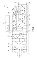
- the conversion element 18 is an electrical converter 30, visible on the figure 2 .
- the electrical converter 30 comprises M input terminals 32, the or each input terminal 32 corresponding to a phase of the AC network 24, a first 34 and a second 36 intermediate terminals, a positive output terminal 38 and a negative terminal of output 40.
- the converter 30 comprises three input terminals 32, the converter 30 being intended to be connected to the three-phase network 24.
- the electric converter 30 comprises a first conversion stage 42 connected between the input terminals 32 and the intermediate terminals 34, 36, a second conversion stage 44 connected at the output of the first stage 42, between the intermediate terminals 34, 36 and the output terminals 38, 40.
- the electric converter 30 also comprises a control member 46 for controlling the second conversion stage 44.
- the first conversion stage 42 comprises a voltage rectifier 48, able to convert the AC input voltage into an intermediate DC voltage and to deliver the intermediate DC voltage to the first and second intermediate terminals 34,36.
- the first conversion stage 42 comprises a filter 50 connected at the output of the voltage rectifier 48.
- the second conversion stage 44 comprises P switching branches 52A, 52B, 52C connected between the intermediate terminals 34, 36, P being an integer greater than or equal to 2, each switching branch 52A, 52B, 52C comprising a first 54A, 54B, 54C and a second 56A, 56B, 56C controllable electronic switches, connected in series and interconnected by a midpoint 58A, 58B, 58C.
- the switching branches 52A, 52B, 52C are connected in parallel between the intermediate terminals 34, 36.
- P is equal to 3 and the second conversion stage 44 comprises a first 52A, a second 52B and a third 52C switching branches.
- each reference comprising the letter 'A' designates an element relating to the first switching branch 52A
- each reference comprising the letter 'B' designates an element relating to the second switching branch 52B
- each reference comprising the letter ' C 'de notes an element relating to the third switching branch 52C.
- the second conversion stage 44 further comprises a capacitor 60 connected between the two output terminals 38, 40 and, for each switching branch 52A, 52B, 52C, an electromagnetic coil 62A, 62B, 62C connected between the midpoint 58A, 58B, 58C of the corresponding switching branch 52A, 52B, 52C and the terminal of the capacitor 60 connected to the positive output terminal 38.
- the second conversion stage 44 comprises a loopback resistor 63 connected between the positive output terminal 38 and the filter 50, in order to control the discharge of the capacitor 60 connected between the two output terminals 38, 40.
- the second conversion stage 44 is reversible and is then adapted to circulate the current from the intermediate terminals 34, 36 to the output terminals 38, 40, and reversibly from the output terminals 38, 40 to the intermediate terminals 34 , 36.
- the control member 46 comprises means 64 for controlling the electronic switches 54A, 54B, 54C, 56A, 56B, 56C according to a control law.
- the voltage rectifier 48 is, for example, in the form of a mixed bridge of thyristors 66 and diodes 68, each thyristor 66 being disposed between a corresponding input terminal 32 and the first intermediate terminal 34 and each diode 68 being arranged between a corresponding input terminal 32 and the second intermediate terminal 36.
- the filter 50 comprises two filter coils 70 each being connected between the voltage rectifier 48 and a corresponding intermediate terminal 34, 36.
- the filter 50 also comprises two filter capacitors 72 connected in series between the intermediate terminals 34, 36 and two filter resistors 74, each being connected in parallel with a corresponding filtering capacitor 72.
- the filter 50 comprises an electronic switch 76 and a diode 78 connected in series between the intermediate terminals 34, 36, the electronic switch 76 being formed of a transistor 80 and a diode 82 connected in antiparallel of the transistor 80.
- the diode 78 is connected in the direction from the second intermediate terminal 36 to the first intermediate terminal 34.
- Each first switch 54A, 54B, 54C is connected between the first intermediate terminal 34 and the corresponding midpoint 58A, 58B, 58C
- each second switch 56A, 56B, 56C is connected between the second intermediate terminal 36 and the midpoint 58A, 58B, 58C corresponding.
- Each switch 54A, 54B, 54C, 56A, 56B, 56C comprises a semiconductor element 84 and a diode 86 connected in antiparallel of the semiconductor element 84, each semiconductor element 84 being switchable between an on state and a blocked state.
- the loopback resistor 63 is connected between, on the one hand, the positive output terminal 38, and on the other hand, the point of connection between the electronic switch 76 and the diode 78 of the filter 50.
- the loopback resistor allows controlling the discharge of the capacitor 60 by switching the electronic switch 76 to maintain a constant voltage at the positive output terminal 38.
- the control means 64 are able to control the semiconductor elements 84 of each switch according to a control law selected from a first control law and a second control law.
- the first control law is such that the semiconductor element 84 of each first switch 54A, 54B, 54C is always in the off state.
- the first control law corresponds to a first mode of operation of the second conversion stage 44.
- the current is able to flow only through the diode 86 corresponding, which operates as a freewheeling diode.
- the second control law is such that the semiconductor element 84 of each second switch 56A, 56B, 56C is always in the off state.
- the second control law corresponds to a second mode of operation of the second conversion stage 44.
- the current is able to flow only through the diode 86, which functions as a freewheeling diode.
- the first control law corresponds to a Boost operation
- the second conversion stage 44 forms, in its first mode of operation, a Boost converter capable of converting the DC voltage between the intermediate terminals 34, 36 to another DC value voltage. higher between the output terminals 38, 40.
- the second control law corresponds to a Buck operation, and the second conversion stage 44 forms, in its second mode of operation, a Buck converter capable of converting the DC voltage between the intermediate terminals 34,36 into another DC voltage of more than low value between the output terminals 38, 40.
- the second mode of operation is distinct from the first mode of operation.
- the control means 64 are able to control the semiconductor elements 84 alternately according to the first control law and according to the second control law, while being adapted to go from the first control law to the second control law and vice versa. from the second control law to the first control law, for example depending on the electric battery to be charged, or the flow direction of the current through the second conversion stage 44, the second conversion stage 44 being reversible.
- the second conversion stage 44 then alternately forms a Boost converter and a Buck converter.
- the conversion stage 44 is able to successively select the first control law and then the second control law in order to switch from an operating mode to a Boost conversion to a mode of operation in Buck conversion, or specific to successively selecting the second control law and then the first control law in order to switch from a mode of operation in Buck conversion to a mode of operation in Boost conversion.
- control means 64 are able to control the semiconductor elements 84 only according to the first control law, and the second conversion stage 44 only forms a Boost converter.
- control means 64 are able to control the semiconductor elements 84 only the second control law, and the second conversion stage 44 forms only a Buck converter.
- control means 64 are able to control the electronic switches 54A, 54B, 54C, 56A, 56B, 56C of the switching branches 52A, 52B, 52C, each according to a specific switching law, and the switching laws are shifted. one of the other.
- the switching laws are, for example, the same frequency F and are then out of phase with each other.
- the phase shift between the switching laws of each of the branches 52A, 52B, 52C is, for example, equal to 360 ° / P, where P is the number of switching branches 52A, 52B, 52C.
- the phase difference between the commutation laws is equal to 120 °.
- phase shift expressed above in degrees
- phase shift can also be expressed in radians, 2 ⁇ radians being equal to 360 °.
- phase shift between the switching laws expressed above in an angular manner can also be expressed temporally by dividing said phase shift expressed in radians by a pulse ⁇ , the pulse ⁇ being equal to 2 ⁇ ⁇ F radians / s, where F is the frequency of the switching laws.
- the semiconductor element 84 is for example a transistor, such as an isolated gate bipolar transistor, also called IGBT transistor (English Insulated Gate Bipolar Transistor ).
- the semiconductor element 84 is a thyristor, such as a Gate Turn Off (GTO) thyristor .
- GTO Gate Turn Off
- the conversion element 18 When a user connects the electrical connector 20 of the recharging terminal with the complementary connector of his motor vehicle 14 in order to recharge the electric battery 12, the conversion element 18 is then connected to the electric battery 12, in order to deliver it a direct current from the alternating current of the network 24.
- the alternating current of the network 24, present at the input terminals 32 of the conversion element, is first converted into direct current by the voltage rectifier 48 of the first conversion stage, then filtered by the filter 50 said first stage.
- the DC voltage present at the intermediate terminals 34, 36 is then converted by the second conversion stage 44 into another DC voltage, the latter being of higher value than the DC voltage between the intermediate terminals 34, 36 when the second conversion stage 44 is in its first mode of operation, or of lower value than the DC voltage between the intermediate terminals 34, 36 when the second conversion stage 44 is in its second mode of operation.
- the control means 64 cyclically control each of the semiconductor elements 84 of the second switches 56A, 56B, 56C of the off-state, then of the on state. in the state blocked, while the semiconductor elements 84 of the first switches 54A, 54B, 54C are still in the off state.
- the control means 64 cyclically control each of the semiconductor elements 84 of the first switches 54A, 54B, 54C of the off-state, then from the on state to the on state. blocked, while the semiconductor elements 84 of the second switches 56A, 56B, 56C are still in the off state.
- the second mode of operation of the second conversion stage 44 also called Buck mode, will be described in more detail below using the Figures 3 to 6 .
- the figure 3 illustrates a first curve 90A, a second curve 90B, a third curve 90C, representing the voltage across the first switch 54A of the first branch, respectively of the first switch 54B of the second branch and respectively of the first switch 54C of the third branch, according to the second mode of operation of the second conversion stage 44.
- the figure 4 illustrates a fourth curve 92A, a fifth curve 92B, a sixth curve 92C, representing the current flowing in the semiconductor element 84 of the first switch 54A of the first branch, respectively of the first switch 54B of the second branch and respectively of the first switch 54C of the third branch, according to the second mode of operation of the second conversion stage 44.
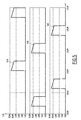
- the figure 5 illustrates a seventh curve 93A, an eighth curve 93B, a ninth curve 93C, representing the current flowing in the diode 86 of the second switch 56A of the first branch, respectively of the second switch 56B of the second branch and respectively of the second switch 56C of the third branch, according to the second mode of operation of the second conversion stage 44.
- the figure 6 illustrates finally a tenth curve 94 and an eleventh curve 95, respectively representing the current Is and the voltage Vs delivered at the output of the converter 30, according to the second mode of operation of the second conversion stage 44.
- said first switch 54A, 54B, 54C is in the closed position, as shown in FIG. figure 3 by the high bearings of the curves 90A, 90B, 90C, for which the value of the voltage across the first switch 54A, 54B, 54C corresponding is approximately 500V and substantially constant.
- the voltage across the corresponding electromagnetic coil 62A, 62B, 62C increases linearly, as shown in FIG. figure 4 by the upwardly inclined segments of curves 92A, 92B, 92C, for which the current value increases from about 18A to about 23A.
- the voltage across the diode 86 of the second switch 56A, 56B, 56B connected in series with said first switch 54A, 54B, 54C in the closed position is negative, and no current then flows through said diode 86, as shown in FIG. figure 5 by the low bearings of the curves 93A, 93B, 93C, for which the value of the current is substantially zero.
- said first switch 54A, 54B, 54C is in the open position, as shown in FIG. figure 3 by the low bearings of the curves 90A, 90B, 90C, for which the value of the voltage across the first switch 54A, 54B, 54C corresponding is substantially zero and constant.
- the diode 86 of the second switch 56A, 56B, 56C connected in series with said first switch 54A, 54B, 54C in the open position becomes conducting.
- the current flowing in the corresponding electromagnetic coil 62A, 62B, 62C then decreases, as shown in FIG. figure 5 by the downwardly inclined segments of curves 93A, 93B, 93C, for which the current value decreases from about 23A to about 18A.
- the current ripple at each switching branch 52A, 52B, 52C is then substantially equal to 5A peak-to-peak.
- the switching laws of the first switches 54A, 54B, 54C are shifted from each other, as shown in FIG. figure 3 where the bottom bearings of curves 90A, 90B, 90C are offset from each other.
- the periods of growth and decay of the current in each of the electromagnetic coils 62A, 62B, 62C are then also shifted from one electromagnetic coil to the other.
- the direct current Is delivered at the output of the converter 30 is slightly greater than 60 A, and the DC voltage is approximately 413 V.
- the parallel connection of the switching branches 52A, 52B, 52C and the electromagnetic coils 62A, 62B, 62C makes it possible to deliver a high output current, of the order of 100A, for a voltage of the order of 500 V, while having semiconductor elements 84 and electromagnetic coils 62A, 62B, 62C inexpensive and compact.
- the electric converter 30 according to the invention has a reduced cost and bulk.
- the figure 7 illustrates the electric converter 30 according to a variant of the first embodiment.
- the converter 30 being connected, on the one hand, to a DC voltage bus Vbus via the intermediate terminals 34 , 36, and on the other hand, the electrical load to supply DC voltage, such as the battery 12 having the DC voltage battery, through the output terminals 38, 40.
- the second conversion stage 44 and the filter 50 are adapted to operate reversibly, the current being able to flow from the DC voltage bus to the electrical load, or vice versa from the electrical load to the DC voltage bus.
- the first mode of operation of the second conversion stage 44 also called the boost mode, will be described in more detail below using the figure 8 .
- the figure 8 illustrates a twelfth curve 96A, a thirteenth curve 96B, a fourteenth curve 96C, representing the current flowing in the semiconductor element 84 of the second switch 56A of the first branch, respectively the second switch 56B of the second branch and the second respectively. switch 56C of the third branch, according to the first mode of operation of the second conversion stage 44.
- the curves 96A, 96B, 96C are represented in fine lines.
- the figure 8 also illustrates a fifteenth curve 97A, a sixteenth curve 97B, a seventeenth curve 97C, representing the current flowing in the diode 86 of the first switch 54A of the first branch, respectively of the first switch 54B of the second branch and respectively of the first switch 54C of the third branch, according to the first mode of operation of the second conversion stage 44.
- the curves 97A, 97B, 97C are represented in thick lines.
- the figure 8 illustrates finally an eighteenth curve 98 and a nineteenth curve 99, representing the current I1 flowing through the load, such as the battery 12, connected at the output of the converter 30, and respectively the current I1 flowing at the input of the converter 30 according to the first mode of operation of the second conversion stage 44, the currents I1 and 10 being represented on the figure 7 .
- Boost converter that is to say the first mode of operation of the second conversion stage 44, is known per se, and is not described in more detail.
- the switching laws of the second switches 56A, 56B, 56C are shifted from one another.
- the periods of growth and decay of the current in each of the electromagnetic coils 62A, 62B, 62C are then also shifted from one electromagnetic coil to the other.
- FIG 9 illustrates a second embodiment of the invention for which elements similar to the first embodiment, described above, are identified by identical references, and are therefore not described again.
- the conversion element 18 is a conversion device 100 comprising a voltage transformer 102 comprising a primary circuit 104, a first secondary circuit 106 and a second secondary circuit 108.
- the conversion device 100 comprises a first electrical converter 110A connected to the first secondary circuit 106 and a second electrical converter 110B connected to the second secondary circuit 108.
- the conversion device 100 also comprises a positive output terminal 111, an output negative terminal 112 and a diode 113 connected between the positive output terminals 38 of the converters 110A, 110B and the positive output terminal 111.
- the positive output terminals 38 of the first converter 110A and the second converter 110B are interconnected.
- the negative output terminals 40 of the first converter 110A and the second converter 110B are also interconnected.
- the primary circuit 104 of the transformer comprises M primary windings, not shown, where M is the number of phases of the reciprocating network 24.
- Each secondary circuit 106, 108 of the transformer comprises M secondary windings, not shown.
- the AC network 24 is a three-phase network
- M is equal to three
- the three primary windings are star-connected.
- the three secondary windings of the first secondary circuit 106 are connected in a triangle
- the three secondary windings of the second secondary circuit 108 are connected in a star.
- Each electrical converter 110A, 110B comprises, in a manner identical to the first embodiment, a first conversion stage 42, a second conversion stage 44 connected at the output of the first stage 42 and a control element 46.
- the first electric converter 110A is, for example, identical to the second electric converter 110B.
- each converter 110A, 110B comprises, for each switching branch 52A, 52B, 52C, a circuit breaker 114A, 114B, 114C connected between the corresponding coil 62A, 62B, 62C and the capacitor 60.
- each converter 110A, 110B comprises a loopback resistor 116 connected between, on the one hand, the output of the circuit breakers 114A, 114B, 114C, and on the other hand, in a manner analogous to the first one.
- the point of connection between the electronic switch 76 and the diode 78 of the filter 50 makes it possible to control the discharge of the capacitor 60 by switching the electronic switch 76 in order to maintain a constant voltage in FIG. the positive output terminal 38.
- the conversion device 100 also makes it possible to improve the quality of energy absorbed at the level of the electrical network 24 by the parallel association of the first converter 110A and the second converter 110B via the two secondary circuits. 106, 108 of the transformer 102. The conversion device 100 then makes it possible to limit the rate of harmonic distortion seen from the AC network 24 and to obtain a better quality of energy absorbed.
- the conversion element 18 according to the invention reduces the cost and bulk, while allowing the passage of strong currents, such as currents of the order of 100 A.
- the second conversion stage 44 is able to operate alternately in Boost conversion and Buck conversion according to the control law selected from the first control law and the second control law.
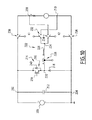
- the figure 10 illustrates a circuit diagram of another conversion element adapted to also move from a Boost operating mode to a Buck operating mode, and vice versa, the transition from a Boost conversion to a Buck conversion and vice versa taking place in this mode. case by switching two contactors, instead of a change of control law, the first control law to the second, and vice versa from the second control law to the first control law, as has been described above.
- the conversion element 200 comprises two input terminals 202, 204, namely a first input terminal 202 and a second input terminal 204, adapted to be connected to a DC voltage source 206 and two terminals of output 208, 210, namely a first output terminal 208 and a second output terminal 210, between which a DC output voltage is adapted to be delivered by the conversion element 200.
- the conversion element 200 comprises a filtering capacitor 212 connected between the two input terminals 202, 204.
- the conversion element 200 also includes a switching branch 214 connected in parallel with the filter capacitor 212, i.e. between the two input terminals 202, 204, the switching branch 214 having a controllable switch 216 and a diode 218 connected in series and interconnected by a midpoint 220.
- the conversion element 200 comprises a transverse branch 222 connected between the midpoint 220 and an intermediate point 224, the transverse branch 222 comprising an electromagnetic coil 226.
- the transverse branch 222 comprises a current sensor 228.
- the conversion element 200 comprises a first contactor K1 and a second contactor K2, the first and second contactors K1, K2 being coupled so that the first contactor K1 is in the closed position when the second contactor K2 is in the open position, and conversely the first contactor K1 is in the open position when the second contactor K2 is in the closed position.
- the first contactor K1 comprises a first switch 230 and a second switch 232, able to be controlled simultaneously in the open position, or in the closed position corresponding to the passage of current through the two switches. 230, 232.
- the first switch 230 is connected between the first input terminal 202 and the first output terminal 208, and the second sensor 132 is connected between the intermediate point 224 and the second output terminal 210.
- the second contactor K2 comprises a third switch 234 and a fourth switch 236, able to be controlled simultaneously in the open position, or in the closed position corresponding to the passage of current through the two switches 234, 236.
- the third switch 234 is connected between the intermediate point 224 and the first output terminal 208
- the fourth switch 236 is connected between the second input terminal 204 and the second output terminal 210.
- the closing of the first contactor K1 that is to say the closing of the first and second switches 230, 232, corresponds to a Boost converter operating mode of the conversion element 200.
- the closing of the second contactor K2, c that is, the closing of the third and fourth switches 234, 236, corresponds to a mode of operation as a Buck converter of the conversion element 200.
- the conversion element 200 is then able to pass simply from a Boost conversion to a Buck conversion by opening the first contactor K1 and closing the second contactor K2, and conversely from a Buck conversion to a Boost conversion by closing the first contactor. K1 and opening of the second contactor K2.
- the controllable switch 216 comprises a semiconductor element 238 and a diode 240 connected in antiparallel to the semiconductor element 238, the semiconductor element 238 being switchable between an on state and a off state.
- the semiconductor element 238 is for example a transistor, such as an insulated gate bipolar transistor, also called IGBT transistor (English Insulated Gate Bipolar Transistor ) .
- the semiconductor element 238 is a thyristor, such as a Gate Turn Off (GTO) thyristor .
- GTO Gate Turn Off
Landscapes
- Engineering & Computer Science (AREA)
- Power Engineering (AREA)
- Transportation (AREA)
- Mechanical Engineering (AREA)
- Dc-Dc Converters (AREA)
- Rectifiers (AREA)
- Charge And Discharge Circuits For Batteries Or The Like (AREA)
Applications Claiming Priority (2)
| Application Number | Priority Date | Filing Date | Title |
|---|---|---|---|
| FR1254136A FR2990310B1 (fr) | 2012-05-04 | 2012-05-04 | Convertisseur electrique, dispositif de conversion d'un courant alternatif en un courant continu comportant un tel convertisseur, et borne de rechargement d'une batterie electrique comportant un tel convertisseur ou dispositif de conversion |
| FR1260799A FR2998115B1 (fr) | 2012-11-13 | 2012-11-13 | Etage de conversion, convertisseur electrique comportant un tel etage de conversion, dispositif de conversion d'un courant alternatif en un courant continu comportant un tel convertisseur, et borne de rechargement d'une batterie electrique comportant un tel convertisseur ou dispositif de conversion |
Publications (3)
| Publication Number | Publication Date |
|---|---|
| EP2660095A2 true EP2660095A2 (de) | 2013-11-06 |
| EP2660095A3 EP2660095A3 (de) | 2017-11-15 |
| EP2660095B1 EP2660095B1 (de) | 2022-11-23 |
Family
ID=48182854
Family Applications (1)
| Application Number | Title | Priority Date | Filing Date |
|---|---|---|---|
| EP13166370.0A Active EP2660095B1 (de) | 2012-05-04 | 2013-05-03 | Wandlerstufe, Stromrichter, der eine solche Wandlerstufe umfasst, Gleichrichter, der einen solchen Stromrichter umfasst, und Batterieladeanordnung, die einen solchen Stromrichter oder eine solche Wandlerstufe umfasst |
Country Status (4)
| Country | Link |
|---|---|
| US (1) | US9270182B2 (de) |
| EP (1) | EP2660095B1 (de) |
| CN (1) | CN103384122B (de) |
| ES (1) | ES2938745T3 (de) |
Cited By (3)
| Publication number | Priority date | Publication date | Assignee | Title |
|---|---|---|---|---|
| CN105365593A (zh) * | 2015-11-06 | 2016-03-02 | 郑州比克新能源汽车有限公司 | 电动汽车充电连接装置及其控制方法 |
| CN107097665A (zh) * | 2017-04-25 | 2017-08-29 | 柳州博泽科技有限公司 | 一种用于汽车充电桩的充放电方法 |
| CN109789807A (zh) * | 2016-09-22 | 2019-05-21 | Ifp新能源公司 | 转换装置、相关联的控制方法以及相关联的交通工具 |
Families Citing this family (6)
| Publication number | Priority date | Publication date | Assignee | Title |
|---|---|---|---|---|
| DE102015200716A1 (de) * | 2015-01-19 | 2016-07-21 | Efficient Energy Gmbh | Schaltnetzteil |
| US10300791B2 (en) * | 2015-12-18 | 2019-05-28 | Ge Global Sourcing Llc | Trolley interfacing device having a pre-charging unit |
| KR101849626B1 (ko) | 2016-03-03 | 2018-04-17 | 계명대학교 산학협력단 | 고효율 전기자동차 충전기 |
| EP3610552B1 (de) * | 2017-06-12 | 2023-11-29 | Gbatteries Energy Canada Inc. | Batterieladen durch mehrstufige spannungswandlung |
| DE102018101312A1 (de) * | 2018-01-22 | 2019-07-25 | Eaton Intelligent Power Limited | Elektrische Schutzschaltungsanordnung |
| CN108790913A (zh) * | 2018-06-29 | 2018-11-13 | 安徽江淮汽车集团股份有限公司 | 一种电动汽车的充电装置 |
Family Cites Families (20)
| Publication number | Priority date | Publication date | Assignee | Title |
|---|---|---|---|---|
| GB1319143A (en) | 1970-10-17 | 1973-06-06 | Gen Battery Corp | Electrical current supply circuit |
| US4920475A (en) | 1988-03-07 | 1990-04-24 | California Institute Of Technology | Integrated traction inverter and battery charger apparatus |
| DE4107391A1 (de) | 1991-03-08 | 1992-09-10 | Abb Patent Gmbh | Elektrofahrzeug mit mindestens einem batteriegespeisten wechselrichter |
| US5157319A (en) | 1991-09-27 | 1992-10-20 | Electric Power Research Institute | Contactless battery charging system |
| US5500579A (en) * | 1995-01-03 | 1996-03-19 | Motorola, Inc. | Electric motor control with integral battery charger |
| US5952812A (en) * | 1996-11-26 | 1999-09-14 | Nippon Soken, Inc. | AC-DC power converting device |
| DE19736786A1 (de) * | 1997-08-23 | 1999-02-25 | Asea Brown Boveri | U-Umrichter |
| US6683389B2 (en) * | 2000-06-30 | 2004-01-27 | Capstone Turbine Corporation | Hybrid electric vehicle DC power generation system |
| US7352154B2 (en) * | 2004-01-14 | 2008-04-01 | Vanner, Inc. | Electrical system control for a vehicle |
| DE102007041510A1 (de) * | 2007-08-31 | 2009-03-05 | Kostal Industrie Elektrik Gmbh | Mehrkanaliger Gleichstromsteller |
| US7889524B2 (en) * | 2007-10-19 | 2011-02-15 | Illinois Institute Of Technology | Integrated bi-directional converter for plug-in hybrid electric vehicles |
| FR2934217B1 (fr) | 2008-07-28 | 2010-08-13 | Renault Sas | Chaine de traction electrique pour vehicule automobile. |
| US8482945B2 (en) * | 2008-09-26 | 2013-07-09 | Merstech, Inc. | Power converter with magnetic recovery switch |
| JP5244653B2 (ja) * | 2009-03-03 | 2013-07-24 | 日立オートモティブシステムズ株式会社 | 電力変換装置 |
| DE102009028959A1 (de) | 2009-08-28 | 2011-03-03 | Robert Bosch Gmbh | Batteriesystem |
| US8421271B2 (en) * | 2009-08-31 | 2013-04-16 | General Electric Company | Apparatus for transferring energy using onboard power electronics and method of manufacturing same |
| SE534910C2 (sv) | 2010-06-14 | 2012-02-14 | Elektrisk apparat innefattande drivsystem och elektrisk maskin med omkopplingsbar statorlindning | |
| US8493032B2 (en) * | 2010-07-20 | 2013-07-23 | Tesla Motors, Inc. | Bidirectional polyphase multimode converter including boost and buck-boost modes |
| DE102010039886B4 (de) | 2010-08-27 | 2013-02-07 | Siemens Aktiengesellschaft | Antriebssystem für ein batteriebetriebenes Fahrzeug |
| US9381819B2 (en) | 2011-06-29 | 2016-07-05 | Ford Global Technologies, Llc | Method and apparatus for charging or discharging and electrical device by controlling switches |
-
2013
- 2013-03-15 US US13/837,794 patent/US9270182B2/en active Active
- 2013-05-03 EP EP13166370.0A patent/EP2660095B1/de active Active
- 2013-05-03 ES ES13166370T patent/ES2938745T3/es active Active
- 2013-05-06 CN CN201310168045.5A patent/CN103384122B/zh active Active
Non-Patent Citations (1)
| Title |
|---|
| None |
Cited By (4)
| Publication number | Priority date | Publication date | Assignee | Title |
|---|---|---|---|---|
| CN105365593A (zh) * | 2015-11-06 | 2016-03-02 | 郑州比克新能源汽车有限公司 | 电动汽车充电连接装置及其控制方法 |
| CN105365593B (zh) * | 2015-11-06 | 2017-06-23 | 郑州比克新能源汽车有限公司 | 电动汽车充电连接装置及其控制方法 |
| CN109789807A (zh) * | 2016-09-22 | 2019-05-21 | Ifp新能源公司 | 转换装置、相关联的控制方法以及相关联的交通工具 |
| CN107097665A (zh) * | 2017-04-25 | 2017-08-29 | 柳州博泽科技有限公司 | 一种用于汽车充电桩的充放电方法 |
Also Published As
| Publication number | Publication date |
|---|---|
| ES2938745T3 (es) | 2023-04-14 |
| EP2660095A3 (de) | 2017-11-15 |
| CN103384122B (zh) | 2018-02-27 |
| US20130293193A1 (en) | 2013-11-07 |
| CN103384122A (zh) | 2013-11-06 |
| US9270182B2 (en) | 2016-02-23 |
| EP2660095B1 (de) | 2022-11-23 |
Similar Documents
| Publication | Publication Date | Title |
|---|---|---|
| EP2660095B1 (de) | Wandlerstufe, Stromrichter, der eine solche Wandlerstufe umfasst, Gleichrichter, der einen solchen Stromrichter umfasst, und Batterieladeanordnung, die einen solchen Stromrichter oder eine solche Wandlerstufe umfasst | |
| EP2859641B1 (de) | Ladevorrichtung mit adaptativem eingang und ladeverfahren | |
| EP3607644B1 (de) | Verfahren zur steuerung einer aufladevorrichtung an bord eines elektro- oder hybridfahrzeugs | |
| EP3682525B1 (de) | Fahrzeuglader mit gleichspannungswandler | |
| EP2794343A2 (de) | Verfahren zum austausch elektrischer energie zwischen einem elektrischen netz zur förderung einer elektrischen gleichstrom- oder wechselstromgrösse und stromenergiespeichereinheit für hybrid- oder elektrofahrzeug | |
| EP3053247B1 (de) | System und verfahren zum laden einer traktionsbatterie mit begrenzung der stromaufnahme parasitärer kapazitäten | |
| EP3539204B1 (de) | Verfahren zur steuerung eines dreiphasigen gleichrichters für eine ladevorrichtung an bord eines elektro- oder hybridfahrzeugs | |
| EP2822800B1 (de) | Verfahren zum entladen mindestens eines kondensators eines elektrischen schaltkreises | |
| EP3171505B1 (de) | Ladevorrichtung für eine zugbatterie eines kraftfahrzeugs mit einem zumindest teilweise elektrischen antrieb | |
| FR2998115A1 (fr) | Etage de conversion, convertisseur electrique comportant un tel etage de conversion, dispositif de conversion d'un courant alternatif en un courant continu comportant un tel convertisseur, et borne de rechargement d'une batterie electrique comportant un tel convertisseur ou dispositif de conversion | |
| EP3681756B1 (de) | Fahrzeuglader mit einem gleichstromwandler | |
| WO2008099087A2 (fr) | Generateur et procede de generation de haute tension continue, depoussiereur utilisant ce generateur | |
| FR2990310A1 (fr) | Convertisseur electrique, dispositif de conversion d'un courant alternatif en un courant continu comportant un tel convertisseur, et borne de rechargement d'une batterie electrique comportant un tel convertisseur ou dispositif de conversion | |
| WO2019110297A1 (fr) | Convertisseur continu-continu avec pre-charge d'un premier reseau electrique a partir d'un deuxieme reseau electrique | |
| EP3539203B1 (de) | Verfahren zur steuerung eines dreiphasigen wechselrichters für eine ladevorrichtung an bord eines elektro- oder hybridfahrzeugs | |
| EP3707800B1 (de) | Verfahren zur steuerung eines batterieladegerätes für elektrische akkumulatoren | |
| FR3079688A1 (fr) | Convertisseur npc quatre bras pour les vehicules electriques et chargeur bidirectionnel comprenant un tel convertisseur | |
| EP4382343A1 (de) | Stromversorgungssystem zur versorgung einer elektrischen last mit einer mehrphasigen spannung und einem hilfsnetz durch eine homopolare komponente dieser spannung, zugehörige elektrische anlage | |
| FR2698499A1 (fr) | Circuit pour faire fonctionner une charge inductive. | |
| EP2683070B1 (de) | Modulares Leistungsumrichtungssystem auf Basis einer asymetrischen Brücke mit primärseitiger Isolationsdiode und mehreren Schaltern | |
| FR3014611A1 (fr) | Dispositif de charge pour vehicule electrique avec une chaine de traction a machine a reluctance commutee | |
| EP3086437A1 (de) | Batterieladegerät, elektrisches system mit einem solchen batterieladegerät, elektrisches fahrzeug mit einem solchen system | |
| BE494707A (de) |
Legal Events
| Date | Code | Title | Description |
|---|---|---|---|
| PUAI | Public reference made under article 153(3) epc to a published international application that has entered the european phase |
Free format text: ORIGINAL CODE: 0009012 |
|
| AK | Designated contracting states |
Kind code of ref document: A2 Designated state(s): AL AT BE BG CH CY CZ DE DK EE ES FI FR GB GR HR HU IE IS IT LI LT LU LV MC MK MT NL NO PL PT RO RS SE SI SK SM TR |
|
| AX | Request for extension of the european patent |
Extension state: BA ME |
|
| PUAL | Search report despatched |
Free format text: ORIGINAL CODE: 0009013 |
|
| AK | Designated contracting states |
Kind code of ref document: A3 Designated state(s): AL AT BE BG CH CY CZ DE DK EE ES FI FR GB GR HR HU IE IS IT LI LT LU LV MC MK MT NL NO PL PT RO RS SE SI SK SM TR |
|
| AX | Request for extension of the european patent |
Extension state: BA ME |
|
| RIC1 | Information provided on ipc code assigned before grant |
Ipc: H02M 3/158 20060101ALI20171012BHEP Ipc: H02J 7/02 20160101ALI20171012BHEP Ipc: H02M 1/32 20070101ALI20171012BHEP Ipc: B60L 11/18 20060101AFI20171012BHEP |
|
| STAA | Information on the status of an ep patent application or granted ep patent |
Free format text: STATUS: REQUEST FOR EXAMINATION WAS MADE |
|
| 17P | Request for examination filed |
Effective date: 20180315 |
|
| RBV | Designated contracting states (corrected) |
Designated state(s): AL AT BE BG CH CY CZ DE DK EE ES FI FR GB GR HR HU IE IS IT LI LT LU LV MC MK MT NL NO PL PT RO RS SE SI SK SM TR |
|
| STAA | Information on the status of an ep patent application or granted ep patent |
Free format text: STATUS: EXAMINATION IS IN PROGRESS |
|
| 17Q | First examination report despatched |
Effective date: 20190222 |
|
| STAA | Information on the status of an ep patent application or granted ep patent |
Free format text: STATUS: EXAMINATION IS IN PROGRESS |
|
| REG | Reference to a national code |
Ref country code: DE Ref legal event code: R079 Ref document number: 602013082905 Country of ref document: DE Free format text: PREVIOUS MAIN CLASS: B60L0011180000 Ipc: B60L0053140000 |
|
| GRAP | Despatch of communication of intention to grant a patent |
Free format text: ORIGINAL CODE: EPIDOSNIGR1 |
|
| STAA | Information on the status of an ep patent application or granted ep patent |
Free format text: STATUS: GRANT OF PATENT IS INTENDED |
|
| RIC1 | Information provided on ipc code assigned before grant |
Ipc: H02M 7/81 20060101ALN20220623BHEP Ipc: H02J 7/02 20060101ALI20220623BHEP Ipc: B60L 53/31 20190101ALI20220623BHEP Ipc: B60L 53/20 20190101ALI20220623BHEP Ipc: B60L 53/14 20190101AFI20220623BHEP |
|
| INTG | Intention to grant announced |
Effective date: 20220713 |
|
| GRAS | Grant fee paid |
Free format text: ORIGINAL CODE: EPIDOSNIGR3 |
|
| GRAA | (expected) grant |
Free format text: ORIGINAL CODE: 0009210 |
|
| STAA | Information on the status of an ep patent application or granted ep patent |
Free format text: STATUS: THE PATENT HAS BEEN GRANTED |
|
| AK | Designated contracting states |
Kind code of ref document: B1 Designated state(s): AL AT BE BG CH CY CZ DE DK EE ES FI FR GB GR HR HU IE IS IT LI LT LU LV MC MK MT NL NO PL PT RO RS SE SI SK SM TR |
|
| REG | Reference to a national code |
Ref country code: GB Ref legal event code: FG4D Free format text: NOT ENGLISH |
|
| REG | Reference to a national code |
Ref country code: CH Ref legal event code: EP |
|
| REG | Reference to a national code |
Ref country code: AT Ref legal event code: REF Ref document number: 1532949 Country of ref document: AT Kind code of ref document: T Effective date: 20221215 Ref country code: DE Ref legal event code: R096 Ref document number: 602013082905 Country of ref document: DE |
|
| REG | Reference to a national code |
Ref country code: IE Ref legal event code: FG4D Free format text: LANGUAGE OF EP DOCUMENT: FRENCH |
|
| REG | Reference to a national code |
Ref country code: LT Ref legal event code: MG9D |
|
| REG | Reference to a national code |
Ref country code: NL Ref legal event code: MP Effective date: 20221123 |
|
| REG | Reference to a national code |
Ref country code: ES Ref legal event code: FG2A Ref document number: 2938745 Country of ref document: ES Kind code of ref document: T3 Effective date: 20230414 |
|
| REG | Reference to a national code |
Ref country code: AT Ref legal event code: MK05 Ref document number: 1532949 Country of ref document: AT Kind code of ref document: T Effective date: 20221123 |
|
| PG25 | Lapsed in a contracting state [announced via postgrant information from national office to epo] |
Ref country code: SE Free format text: LAPSE BECAUSE OF FAILURE TO SUBMIT A TRANSLATION OF THE DESCRIPTION OR TO PAY THE FEE WITHIN THE PRESCRIBED TIME-LIMIT Effective date: 20221123 Ref country code: PT Free format text: LAPSE BECAUSE OF FAILURE TO SUBMIT A TRANSLATION OF THE DESCRIPTION OR TO PAY THE FEE WITHIN THE PRESCRIBED TIME-LIMIT Effective date: 20230323 Ref country code: NO Free format text: LAPSE BECAUSE OF FAILURE TO SUBMIT A TRANSLATION OF THE DESCRIPTION OR TO PAY THE FEE WITHIN THE PRESCRIBED TIME-LIMIT Effective date: 20230223 Ref country code: LT Free format text: LAPSE BECAUSE OF FAILURE TO SUBMIT A TRANSLATION OF THE DESCRIPTION OR TO PAY THE FEE WITHIN THE PRESCRIBED TIME-LIMIT Effective date: 20221123 Ref country code: FI Free format text: LAPSE BECAUSE OF FAILURE TO SUBMIT A TRANSLATION OF THE DESCRIPTION OR TO PAY THE FEE WITHIN THE PRESCRIBED TIME-LIMIT Effective date: 20221123 Ref country code: AT Free format text: LAPSE BECAUSE OF FAILURE TO SUBMIT A TRANSLATION OF THE DESCRIPTION OR TO PAY THE FEE WITHIN THE PRESCRIBED TIME-LIMIT Effective date: 20221123 |
|
| PG25 | Lapsed in a contracting state [announced via postgrant information from national office to epo] |
Ref country code: RS Free format text: LAPSE BECAUSE OF FAILURE TO SUBMIT A TRANSLATION OF THE DESCRIPTION OR TO PAY THE FEE WITHIN THE PRESCRIBED TIME-LIMIT Effective date: 20221123 Ref country code: PL Free format text: LAPSE BECAUSE OF FAILURE TO SUBMIT A TRANSLATION OF THE DESCRIPTION OR TO PAY THE FEE WITHIN THE PRESCRIBED TIME-LIMIT Effective date: 20221123 Ref country code: LV Free format text: LAPSE BECAUSE OF FAILURE TO SUBMIT A TRANSLATION OF THE DESCRIPTION OR TO PAY THE FEE WITHIN THE PRESCRIBED TIME-LIMIT Effective date: 20221123 Ref country code: IS Free format text: LAPSE BECAUSE OF FAILURE TO SUBMIT A TRANSLATION OF THE DESCRIPTION OR TO PAY THE FEE WITHIN THE PRESCRIBED TIME-LIMIT Effective date: 20230323 Ref country code: HR Free format text: LAPSE BECAUSE OF FAILURE TO SUBMIT A TRANSLATION OF THE DESCRIPTION OR TO PAY THE FEE WITHIN THE PRESCRIBED TIME-LIMIT Effective date: 20221123 Ref country code: GR Free format text: LAPSE BECAUSE OF FAILURE TO SUBMIT A TRANSLATION OF THE DESCRIPTION OR TO PAY THE FEE WITHIN THE PRESCRIBED TIME-LIMIT Effective date: 20230224 |
|
| PG25 | Lapsed in a contracting state [announced via postgrant information from national office to epo] |
Ref country code: NL Free format text: LAPSE BECAUSE OF FAILURE TO SUBMIT A TRANSLATION OF THE DESCRIPTION OR TO PAY THE FEE WITHIN THE PRESCRIBED TIME-LIMIT Effective date: 20221123 |
|
| PG25 | Lapsed in a contracting state [announced via postgrant information from national office to epo] |
Ref country code: SM Free format text: LAPSE BECAUSE OF FAILURE TO SUBMIT A TRANSLATION OF THE DESCRIPTION OR TO PAY THE FEE WITHIN THE PRESCRIBED TIME-LIMIT Effective date: 20221123 Ref country code: RO Free format text: LAPSE BECAUSE OF FAILURE TO SUBMIT A TRANSLATION OF THE DESCRIPTION OR TO PAY THE FEE WITHIN THE PRESCRIBED TIME-LIMIT Effective date: 20221123 Ref country code: EE Free format text: LAPSE BECAUSE OF FAILURE TO SUBMIT A TRANSLATION OF THE DESCRIPTION OR TO PAY THE FEE WITHIN THE PRESCRIBED TIME-LIMIT Effective date: 20221123 Ref country code: DK Free format text: LAPSE BECAUSE OF FAILURE TO SUBMIT A TRANSLATION OF THE DESCRIPTION OR TO PAY THE FEE WITHIN THE PRESCRIBED TIME-LIMIT Effective date: 20221123 Ref country code: CZ Free format text: LAPSE BECAUSE OF FAILURE TO SUBMIT A TRANSLATION OF THE DESCRIPTION OR TO PAY THE FEE WITHIN THE PRESCRIBED TIME-LIMIT Effective date: 20221123 |
|
| PGFP | Annual fee paid to national office [announced via postgrant information from national office to epo] |
Ref country code: IT Payment date: 20230525 Year of fee payment: 11 |
|
| REG | Reference to a national code |
Ref country code: DE Ref legal event code: R097 Ref document number: 602013082905 Country of ref document: DE |
|
| PG25 | Lapsed in a contracting state [announced via postgrant information from national office to epo] |
Ref country code: SK Free format text: LAPSE BECAUSE OF FAILURE TO SUBMIT A TRANSLATION OF THE DESCRIPTION OR TO PAY THE FEE WITHIN THE PRESCRIBED TIME-LIMIT Effective date: 20221123 Ref country code: AL Free format text: LAPSE BECAUSE OF FAILURE TO SUBMIT A TRANSLATION OF THE DESCRIPTION OR TO PAY THE FEE WITHIN THE PRESCRIBED TIME-LIMIT Effective date: 20221123 |
|
| PLBE | No opposition filed within time limit |
Free format text: ORIGINAL CODE: 0009261 |
|
| STAA | Information on the status of an ep patent application or granted ep patent |
Free format text: STATUS: NO OPPOSITION FILED WITHIN TIME LIMIT |
|
| 26N | No opposition filed |
Effective date: 20230824 |
|
| PG25 | Lapsed in a contracting state [announced via postgrant information from national office to epo] |
Ref country code: SI Free format text: LAPSE BECAUSE OF FAILURE TO SUBMIT A TRANSLATION OF THE DESCRIPTION OR TO PAY THE FEE WITHIN THE PRESCRIBED TIME-LIMIT Effective date: 20221123 |
|
| REG | Reference to a national code |
Ref country code: CH Ref legal event code: PL |
|
| PG25 | Lapsed in a contracting state [announced via postgrant information from national office to epo] |
Ref country code: MC Free format text: LAPSE BECAUSE OF FAILURE TO SUBMIT A TRANSLATION OF THE DESCRIPTION OR TO PAY THE FEE WITHIN THE PRESCRIBED TIME-LIMIT Effective date: 20221123 |
|
| REG | Reference to a national code |
Ref country code: BE Ref legal event code: MM Effective date: 20230531 |
|
| PG25 | Lapsed in a contracting state [announced via postgrant information from national office to epo] |
Ref country code: MC Free format text: LAPSE BECAUSE OF FAILURE TO SUBMIT A TRANSLATION OF THE DESCRIPTION OR TO PAY THE FEE WITHIN THE PRESCRIBED TIME-LIMIT Effective date: 20221123 Ref country code: LU Free format text: LAPSE BECAUSE OF NON-PAYMENT OF DUE FEES Effective date: 20230503 Ref country code: LI Free format text: LAPSE BECAUSE OF NON-PAYMENT OF DUE FEES Effective date: 20230531 Ref country code: CH Free format text: LAPSE BECAUSE OF NON-PAYMENT OF DUE FEES Effective date: 20230531 |
|
| REG | Reference to a national code |
Ref country code: IE Ref legal event code: MM4A |
|
| PG25 | Lapsed in a contracting state [announced via postgrant information from national office to epo] |
Ref country code: IE Free format text: LAPSE BECAUSE OF NON-PAYMENT OF DUE FEES Effective date: 20230503 |
|
| PG25 | Lapsed in a contracting state [announced via postgrant information from national office to epo] |
Ref country code: IE Free format text: LAPSE BECAUSE OF NON-PAYMENT OF DUE FEES Effective date: 20230503 |
|
| PG25 | Lapsed in a contracting state [announced via postgrant information from national office to epo] |
Ref country code: BE Free format text: LAPSE BECAUSE OF NON-PAYMENT OF DUE FEES Effective date: 20230531 |
|
| PGFP | Annual fee paid to national office [announced via postgrant information from national office to epo] |
Ref country code: GB Payment date: 20240521 Year of fee payment: 12 |
|
| PGFP | Annual fee paid to national office [announced via postgrant information from national office to epo] |
Ref country code: DE Payment date: 20240529 Year of fee payment: 12 |
|
| PGFP | Annual fee paid to national office [announced via postgrant information from national office to epo] |
Ref country code: ES Payment date: 20240610 Year of fee payment: 12 |
|
| PGFP | Annual fee paid to national office [announced via postgrant information from national office to epo] |
Ref country code: FR Payment date: 20240527 Year of fee payment: 12 |