EP2658459B1 - Intramedullary nail with shape memory elements for long bones - Google Patents
Intramedullary nail with shape memory elements for long bones Download PDFInfo
- Publication number
- EP2658459B1 EP2658459B1 EP20110810803 EP11810803A EP2658459B1 EP 2658459 B1 EP2658459 B1 EP 2658459B1 EP 20110810803 EP20110810803 EP 20110810803 EP 11810803 A EP11810803 A EP 11810803A EP 2658459 B1 EP2658459 B1 EP 2658459B1
- Authority
- EP
- European Patent Office
- Prior art keywords
- shape
- rod
- intramedullary nail
- distal
- memory elements
- Prior art date
- Legal status (The legal status is an assumption and is not a legal conclusion. Google has not performed a legal analysis and makes no representation as to the accuracy of the status listed.)
- Active
Links
Images



Classifications
-
- A—HUMAN NECESSITIES
- A61—MEDICAL OR VETERINARY SCIENCE; HYGIENE
- A61B—DIAGNOSIS; SURGERY; IDENTIFICATION
- A61B17/00—Surgical instruments, devices or methods
- A61B17/56—Surgical instruments or methods for treatment of bones or joints; Devices specially adapted therefor
- A61B17/58—Surgical instruments or methods for treatment of bones or joints; Devices specially adapted therefor for osteosynthesis, e.g. bone plates, screws or setting implements
- A61B17/68—Internal fixation devices, including fasteners and spinal fixators, even if a part thereof projects from the skin
- A61B17/72—Intramedullary devices, e.g. pins or nails
- A61B17/7233—Intramedullary devices, e.g. pins or nails with special means of locking the nail to the bone
- A61B17/7258—Intramedullary devices, e.g. pins or nails with special means of locking the nail to the bone with laterally expanding parts, e.g. for gripping the bone
-
- A—HUMAN NECESSITIES
- A61—MEDICAL OR VETERINARY SCIENCE; HYGIENE
- A61B—DIAGNOSIS; SURGERY; IDENTIFICATION
- A61B17/00—Surgical instruments, devices or methods
- A61B2017/00831—Material properties
- A61B2017/00867—Material properties shape memory effect
Definitions
- the present invention refers, in its most general aspect, to an intramedullary nail suitable to be inserted into a fractured elongated bone, for example a femur or a tibia, and comprising a cannulated rod extending between a proximal end and a distal end.
- the invention relates to a nail comprising:
- Intramedullary nails are known in the field and used in surgical interventions, where they are inserted into a fractured elongated bone to return consistency to the bone and allow the mechanism of bone callus regeneration to take place correctly
- These nails comprise a stem or rod having a cylindrical shape and they are either solid or hollow; in the latter case the rod is cannulated.
- two offset holes are provided on the nail, with axes lying on parallel planes and extending diametrically across the rod in correspondence with the distal end of the nail.
- two further offset holes are provided in correspondence with the proximal end of the nail with axis lying on parallel planes.
- These holes are intended to receive bone screws inserted into the bone after the appropriate holes have been drilled in the bone, in this manner fastening the intramedullary nail inside the fractured bone.
- the technical problem of the present invention is that of providing an intramedullary nail with structural and functional features that overcome all the drawbacks of the prior art solutions through a simpler nail construction for housing the shape-memory elements.
- Another object of the nail of the present invention is that of providing a nail that improves the stabilization phase before a final stable configuration is reached during the nail installation.
- a further object of the present invention is that of providing an intramedullary nail that will be easier to remove when the bone fracture is fully consolidated.
- the idea at the basis of the present invention is that of providing an intramedullary nail to be inserted into a fractured elongated bone according to claim 1.
- 1 generally indicates an intramedullary nail in accordance with the present invention, intended to be inserted into a fractured elongated bone, for instance a femur.
- the nail 1 is provided with an anatomic shape having a proximal 5° curvature to follow the shape of the femoral bone.
- the nail 1 comprises an inner rod 2 extending between a proximal end 3 and a distal end 4.
- the nail 1 further comprises an outside tubular sleeve 5 housing the rod 2 that is inserted coaxially into the tubular sleeve 5.
- the nail 1 and its main components, the rod 2 and the sleeve 5 are curved or bent so that the axis x'-x' of the proximal end portion forms a small angle of 5° with the axis x"-x" of the remaining body and distal end portions of the nail 1.
- the nail 1 and its main components, the rod 2 and the sleeve 5 are cylindrical.
- Both the sleeve 5 and the rod 2 comprise a pair of transversal holes in the proximal portion of both components; these holes are intended to receive bone screws and have their respective axes for the insertion of the bone screw lying on a common plane.
- the sleeve 5 comprises a couple of transversal holes or slots 13 and 14 that are provided transversally with respect to the axis of the nail to allow the passage of bone screws.
- the more proximal slot 13 is axially longer that the other slot 14.
- the slots 13, 14 are provided in opposite and coaxial portions of the perimeter wall of the proximal portion of the sleeve. Both slots 13, 14 have their corresponding through holes parallel to each other.
- the rod 2 shown in figure 3 is cannulated, that is to say it has an internal cavity that extends longitudinally.
- the rod may be cannulated along its entire length, as a feature that is used to house a guide wire, for example a Kirschner wire, for use during the insertion into the bone medullary canal.
- the inner rod 2 is housed slidingly inside the tubular sleeve 5. More specifically, the rod 2 is axially movable inside the sleeve 5 and driven by an external device attached to the proximal end of the nail 1.
- the rod 2 comprises a couple of proximal transversal passages 23, 24 in the proximal portion.
- the more proximal passage 23 is a slot that substantially corresponds in shape and extension with the slot 13 of the sleeve 5.
- the other passage 24 is a through-hole that receives a stabilization screw and this passage has its axis corresponding to the axis of the slot 14 of the sleeve 5 when the rod 2 is in the right position inside the sleeve 5.
- a threading 26 is provided for a threaded connection with a suitable driving tool, not shown, for gripping the rod 2 of the nail 1.
- the proximal end of the tubular sleeve 5 comprises an attachment system 21, for instance of the bayonet type; however, any other fastening system known in the field can be used.
- the rod 2 comprises some distal seats 6 for receiving active elements 7 made of at least a shape-memory material.
- the active elements 7 are preferably similar to each other.
- Each element 7 has substantially a fork-like shape with two little wings 15 connected by a central portion or core 16.
- the seats 6 are in the form of a passing opening 18 for housing the core 16 of the active elements 7 and two lateral recesses 10 for housing the wings 15 of the active elements when in the retracted position.
- the elements 7 can assume different configurations, from a first configuration in which they are fully hidden inside their seat 6 to an extended configuration in which they protrude from the seats of the rod projecting from the corresponding slots 8 provided in the sleeve 5.
- the active elements 7 are structured and suitable to take a first shape or configuration, in which each of the elements 7 is retractably housed in its respective seat 6, with the wings 15 housed by the recesses 10, so as to allow the insertion of the nail into the bone.
- Another shape or configuration is taken in which said wings 15 of the active elements 7 project from the respective recesses 10 of the seats 6 to abut against and grip the internal wall of the medullary canal of the fractured bone.
- shape-memory material we mean a material, known in the art, that has a given starting shape and that takes, under predetermined external conditions or when undergoing a predetermined activation condition, also called “material instruction”, a given new shape but that returns to the initial shape when the material instructions are deactivated.
- the starting shape may correspond to the configuration in which the shape-memory elements 7 are arranged projecting from the seats 6 of the rod 2.
- the starting shape might even correspond to the configuration in which the elements 7 are retracted and housed into the seats.
- shape-memory elements 7 may be realized with Shape-Memory Alloy, it is preferable to use SIM materials, i.e. materials sensible to Stress-Induced Martensite, for instance Nitinol, an alloy of Nickel and Titanium.
- SIM materials i.e. materials sensible to Stress-Induced Martensite, for instance Nitinol, an alloy of Nickel and Titanium.
- shape-memory material Another characteristic of the shape-memory material lies in the fact that the transition from the first to the second shape, or configuration, is reversible, i.e. the shape-memory elements can be change from the second to the first shape, or configuration, allowing the extraction of the nail from the bone.
- the nail 1 of the invention is structured with a pair 11 of elements 7 located at the distal end 4 of the nail 1. We will call this pair 11 of shape-memory elements 7 the distal pair.
- a first shape-memory element 7 and a second shape-memory element 7 forming the distal pair 11 lie on an offset plane with respect to each other and also both the first and the second shape-memory elements 7 of the distal pair 11 lie on a respective offset plane with respect to the common plane on which the transversal passages 13, 14 and the holes 23, 24 lie.
- one shape-memory element 7 of the distal pair 11 is oriented at +45° and the other shape-memory element 7 of the distal pair 11 is oriented at -45° with respect to the common plane on which the axis of the slots 13, 14 and passages 23, 24 lie.
- first and second element 7 of the distal pair 11 are angularly spaced by 90° from one another.
- distal elements 7 are offset with one another, for example with an offset of 90° sexagesimal, ensures a determined stability on orthogonal planes and it is useful for granting the nail 1 a better grip inside the medullary canal.
- the shape-memory elements of the present invention are structurally independent from the rod 2 and are housed in their corresponding seats 6 of the distal portion of rod 2 but firmly kept in these seats by a distal cover 12.
- the central core 16 of each element 7 is firmly kept in its seat 6 by the cover 12, while the wings 15 of the elements 7 are freely movable through the openings between the cover 12 and the rod 2 and through the slot 8.
- the distal cover 12 has a particular configuration that cooperate with the distal end of the rod to be covered.
- the cover 12 is fixed to the distal rod portion of the uncovered rod by soldering or other fixing techniques.
- each seat 6 is formed by an opening 18 for receiving the core 16 of a shape-memory element 7 and by a couple of opposite recesses 10 for receiving each wing 15 of the same shape-memory element 7 when in the retracted configuration.
- the distal cover 12 is formed by two portions 20 and 22 that are connected at their respective end forming a single piece and each portion lies on a respective plane which is perpendicular with respect to the other.
- Both portions 20, 22 have a concave outside surface that continues the cylindrical surface of the rod 2 when the distal cover is mounted and fixed to the rod 2 to keep the distal pair 11 of shape-memory elements 7 in position.
- One of the two portions, numbered 20, of the distal cover 12 is internally flat while the other portion 22 has an elongated internal element having a shape conformed to cooperate with a corresponding internal element provided on the distal end 4 of the rod 2.
- the coupling between the distal cover 12 and the distal end of the rod 2 guarantees the continuity of the cylindrical external surface of the cannulated rod 2.
- the tip portion of the sleeve 5 is preferably rounded so as to allow the nail to slide smoothly into said medullary canal.
- a structurally independent rounded tip 25 is provided to be fixed to the distal end of the sleeve 5.
- the tip 25 is soldered to the distal end of the sleeve 5 once the rod 2 has already been inserted into the sleeve.
- the intramedullary nail according to the present invention meets the requirements and overcomes the drawbacks mentioned in the introductory part of the present description with reference to the prior art solutions.
- a clear advantage of the nail according to the present invention is the fact that only one transversal stabilizing screw provided in the proximal nail portion is needed to stabilize the nail in the medullary canal.
- proximal screws with distal shape-memory elements Another advantage of the combination of proximal screws with distal shape-memory elements is the fact that a nail arranged in this manner has the double advantages of nails made of shape-memory material and classic nails bone screws.
Landscapes
- Health & Medical Sciences (AREA)
- Orthopedic Medicine & Surgery (AREA)
- Surgery (AREA)
- Life Sciences & Earth Sciences (AREA)
- Heart & Thoracic Surgery (AREA)
- Nuclear Medicine, Radiotherapy & Molecular Imaging (AREA)
- Engineering & Computer Science (AREA)
- Biomedical Technology (AREA)
- Neurology (AREA)
- Medical Informatics (AREA)
- Molecular Biology (AREA)
- Animal Behavior & Ethology (AREA)
- General Health & Medical Sciences (AREA)
- Public Health (AREA)
- Veterinary Medicine (AREA)
- Surgical Instruments (AREA)
Description
- The present invention refers, in its most general aspect, to an intramedullary nail suitable to be inserted into a fractured elongated bone, for example a femur or a tibia, and comprising a cannulated rod extending between a proximal end and a distal end.
- More particularly, the invention relates to a nail comprising:
- a cannulated rod extending between a proximal end and a distal end;
- an outside tubular sleeve for housing said rod, the rod being coaxial with the sleeve and axially guided inside the tubular sleeve;
- shape-memory elements housed in corresponding seats on said rod; each of the elements being able to assume a configuration in which it is retractably housed in its respective seat, so as to allow the insertion of the nail in the bone, and another configuration in which said elements project from slots in said sleeve.
- Intramedullary nails are known in the field and used in surgical interventions, where they are inserted into a fractured elongated bone to return consistency to the bone and allow the mechanism of bone callus regeneration to take place correctly
- These nails comprise a stem or rod having a cylindrical shape and they are either solid or hollow; in the latter case the rod is cannulated.
- In order to fix the intramedullary nail to the bone portions that are to be reconstructed, usually two offset holes are provided on the nail, with axes lying on parallel planes and extending diametrically across the rod in correspondence with the distal end of the nail. Generally two further offset holes are provided in correspondence with the proximal end of the nail with axis lying on parallel planes.
- These holes are intended to receive bone screws inserted into the bone after the appropriate holes have been drilled in the bone, in this manner fastening the intramedullary nail inside the fractured bone.
- Although still widely used these commonly known nails have known drawbacks as a result of the fact that holes have to be drilled for the insertion of bone screws. These holes have to be in correspondence with the holes of the inserted intramedullary nail, but since the distal nail holes are not visible, X-ray techniques are needed, causing cumulative exposure to X-ray of the operating staff and great inconvenience during the surgical operation.
- More recently alternative nail structures have been proposed. European patent No.
EP 1 740 113 and International Publication No.WO 2005/094706A1 owned by the same Applicant, for instance, disclose an intramedullary nail that can be inserted into a fractured elongate bone, comprising a straight stem extending between a proximal end and a distal end and further comprising a plurality of elements made of at least a shape-memory material. The free end of these shape-memory elements are positioned on the outside of the stem for fixation of the nail to the bone. - Whilst advantageous from many points of views, such nails with shape-memory elements also have some drawbacks that are still to be overcome.
- For instance, due to the absence of bone screws, there is no complete stability of the nail inside the medullary canal and against the high axial stresses caused by a patient's body weight. When this kind of stress is applied, the nail becomes unstable and may even compromise the process of osteosynthesis or cause anomalies in the healing process.
- The technical problem of the present invention is that of providing an intramedullary nail with structural and functional features that overcome all the drawbacks of the prior art solutions through a simpler nail construction for housing the shape-memory elements.
- Another object of the nail of the present invention is that of providing a nail that improves the stabilization phase before a final stable configuration is reached during the nail installation.
- A further object of the present invention is that of providing an intramedullary nail that will be easier to remove when the bone fracture is fully consolidated.
- The idea at the basis of the present invention is that of providing an intramedullary nail to be inserted into a fractured elongated bone according to
claim 1. - The dependent claims outline preferred and particularly advantageous embodiments of intramedullary nail according to the invention.
- Further features and advantages of the intramedullary nail according to the invention shall become clearer from the following description of an example embodiment thereof, given by way of illustrative and nonlimiting purposes and with reference to the attached drawings.
-
-
Figure 1 illustrates a perspective view of a nail according to the invention split into its components; -
Figure 2 illustrates an elevation view of a tubular sleeve of the nail offigure 1 ; -
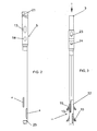
Figure 3 illustrates an elevation view of a cannulated rod of the nail offigure 1 ; -
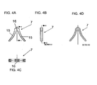
Figures 4A-4D illustrate front, side, top and cross-section views of a shape-memory element incorporated in the nail of the present invention; -
Figure 5 illustrates a perspective view of a detail of a distal end portion of the cannulated rod offigure 3 with seats for the shape-memory elements offigures 4A-4D ; -
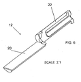
Figure 6 is a perspective view of a distal cover of the cannulated rod shown infigure 3 ; -
Figure 7 is a side view of a detail of a proximal end portion of the cannulated rod offigure 3 ; -
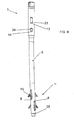
Figure 8 is a side elongated view of the cannulated rod offigure 3 with the distal cover removed; -
Figure 9 is an elevated front view of the nail of the present invention in its assembled configuration. - With reference to the aforementioned
figures, 1 generally indicates an intramedullary nail in accordance with the present invention, intended to be inserted into a fractured elongated bone, for instance a femur. - In case of a femoral nail, the
nail 1 is provided with an anatomic shape having a proximal 5° curvature to follow the shape of the femoral bone. - The
nail 1 comprises aninner rod 2 extending between aproximal end 3 and adistal end 4. - The
nail 1 further comprises an outsidetubular sleeve 5 housing therod 2 that is inserted coaxially into thetubular sleeve 5. - Consequently, the
nail 1 and its main components, therod 2 and thesleeve 5 are curved or bent so that the axis x'-x' of the proximal end portion forms a small angle of 5° with the axis x"-x" of the remaining body and distal end portions of thenail 1. - Preferably, the
nail 1 and its main components, therod 2 and thesleeve 5 are cylindrical. - Both the
sleeve 5 and therod 2 comprise a pair of transversal holes in the proximal portion of both components; these holes are intended to receive bone screws and have their respective axes for the insertion of the bone screw lying on a common plane. - More specifically, the
sleeve 5 comprises a couple of transversal holes orslots - The more
proximal slot 13 is axially longer that theother slot 14. - Since the
sleeve 5 is tubular, theslots slots -
Further slots 8 are provided in the distal portion of thesleeve 5. These distal slots are angularly offset by 90° with respect to each other and respectively angularly offset by +45° and -45° with respect to theproximal slots - The
rod 2 shown infigure 3 is cannulated, that is to say it has an internal cavity that extends longitudinally. The rod may be cannulated along its entire length, as a feature that is used to house a guide wire, for example a Kirschner wire, for use during the insertion into the bone medullary canal. - In accordance with the present invention the
inner rod 2 is housed slidingly inside thetubular sleeve 5. More specifically, therod 2 is axially movable inside thesleeve 5 and driven by an external device attached to the proximal end of thenail 1. - The
rod 2 comprises a couple of proximaltransversal passages - The more
proximal passage 23 is a slot that substantially corresponds in shape and extension with theslot 13 of thesleeve 5. Theother passage 24 is a through-hole that receives a stabilization screw and this passage has its axis corresponding to the axis of theslot 14 of thesleeve 5 when therod 2 is in the right position inside thesleeve 5. - What is important is that the relative axially guided movement of the
rod 2 inside thesleeve 5 can place theslots sleeve 5 to coincide with thecorresponding passages rod 2. - In a head portion of the rod 2 a
threading 26 is provided for a threaded connection with a suitable driving tool, not shown, for gripping therod 2 of thenail 1. - In order to allow easy insertion of the
nail 1 in the medullary canal an external instrument is foreseen that may be attached to the proximal end of thetubular sleeve 5. To make this connection possible, the proximal end of thetubular sleeve 5 comprises anattachment system 21, for instance of the bayonet type; however, any other fastening system known in the field can be used. - The
rod 2 comprises somedistal seats 6 for receivingactive elements 7 made of at least a shape-memory material. - The
active elements 7 are preferably similar to each other. - Each
element 7 has substantially a fork-like shape with twolittle wings 15 connected by a central portion orcore 16. - The
seats 6 are in the form of a passingopening 18 for housing thecore 16 of theactive elements 7 and twolateral recesses 10 for housing thewings 15 of the active elements when in the retracted position. - Because of their shape-memory feature the
elements 7 can assume different configurations, from a first configuration in which they are fully hidden inside theirseat 6 to an extended configuration in which they protrude from the seats of the rod projecting from the correspondingslots 8 provided in thesleeve 5. - In other words, the
active elements 7 are structured and suitable to take a first shape or configuration, in which each of theelements 7 is retractably housed in itsrespective seat 6, with thewings 15 housed by therecesses 10, so as to allow the insertion of the nail into the bone. Another shape or configuration is taken in which saidwings 15 of theactive elements 7 project from therespective recesses 10 of theseats 6 to abut against and grip the internal wall of the medullary canal of the fractured bone. - With the term "shape-memory material" we mean a material, known in the art, that has a given starting shape and that takes, under predetermined external conditions or when undergoing a predetermined activation condition, also called "material instruction", a given new shape but that returns to the initial shape when the material instructions are deactivated.
- For the meaning of the present invention, the starting shape may correspond to the configuration in which the shape-
memory elements 7 are arranged projecting from theseats 6 of therod 2. However, according to the material used, the starting shape might even correspond to the configuration in which theelements 7 are retracted and housed into the seats. - It must be noted that, while the shape-
memory elements 7 may be realized with Shape-Memory Alloy, it is preferable to use SIM materials, i.e. materials sensible to Stress-Induced Martensite, for instance Nitinol, an alloy of Nickel and Titanium. - Another characteristic of the shape-memory material lies in the fact that the transition from the first to the second shape, or configuration, is reversible, i.e. the shape-memory elements can be change from the second to the first shape, or configuration, allowing the extraction of the nail from the bone.
- The
nail 1 of the invention is structured with apair 11 ofelements 7 located at thedistal end 4 of thenail 1. We will call thispair 11 of shape-memory elements 7 the distal pair. - Advantageously a first shape-
memory element 7 and a second shape-memory element 7 forming thedistal pair 11 lie on an offset plane with respect to each other and also both the first and the second shape-memory elements 7 of thedistal pair 11 lie on a respective offset plane with respect to the common plane on which thetransversal passages holes - More particularly, one shape-
memory element 7 of thedistal pair 11 is oriented at +45° and the other shape-memory element 7 of thedistal pair 11 is oriented at -45° with respect to the common plane on which the axis of theslots passages - Therefore, the first and
second element 7 of thedistal pair 11 are angularly spaced by 90° from one another. - The fact that the
distal elements 7 are offset with one another, for example with an offset of 90° sexagesimal, ensures a determined stability on orthogonal planes and it is useful for granting the nail 1 a better grip inside the medullary canal. - Advantageously, the shape-memory elements of the present invention are structurally independent from the
rod 2 and are housed in theircorresponding seats 6 of the distal portion ofrod 2 but firmly kept in these seats by adistal cover 12. Thecentral core 16 of eachelement 7 is firmly kept in itsseat 6 by thecover 12, while thewings 15 of theelements 7 are freely movable through the openings between thecover 12 and therod 2 and through theslot 8. - The
distal cover 12 has a particular configuration that cooperate with the distal end of the rod to be covered. - The
cover 12 is fixed to the distal rod portion of the uncovered rod by soldering or other fixing techniques. - The
cover 12, once fixed to the rod, might be considered forming a common piece forming therod 2 so that eachseat 6 is formed by anopening 18 for receiving thecore 16 of a shape-memory element 7 and by a couple ofopposite recesses 10 for receiving eachwing 15 of the same shape-memory element 7 when in the retracted configuration. - In more detail, the
distal cover 12 is formed by twoportions - Both
portions rod 2 when the distal cover is mounted and fixed to therod 2 to keep thedistal pair 11 of shape-memory elements 7 in position. - One of the two portions, numbered 20, of the
distal cover 12 is internally flat while theother portion 22 has an elongated internal element having a shape conformed to cooperate with a corresponding internal element provided on thedistal end 4 of therod 2. - The coupling between the
distal cover 12 and the distal end of therod 2 guarantees the continuity of the cylindrical external surface of the cannulatedrod 2. - To facilitate the insertion of the
nail 1 into the medullary canal of the fractured bone, the tip portion of thesleeve 5 is preferably rounded so as to allow the nail to slide smoothly into said medullary canal. - More specifically, a structurally independent
rounded tip 25 is provided to be fixed to the distal end of thesleeve 5. - The
tip 25 is soldered to the distal end of thesleeve 5 once therod 2 has already been inserted into the sleeve. - It must be noted that such a
tip 25 maintains the opening of the cannulatedrod 2, which has an open end. - As can be appreciated from what has been described, the intramedullary nail according to the present invention meets the requirements and overcomes the drawbacks mentioned in the introductory part of the present description with reference to the prior art solutions.
- A clear advantage of the nail according to the present invention is the fact that only one transversal stabilizing screw provided in the proximal nail portion is needed to stabilize the nail in the medullary canal.
- Another advantage of the combination of proximal screws with distal shape-memory elements is the fact that a nail arranged in this manner has the double advantages of nails made of shape-memory material and classic nails bone screws.
- Of course, a person skilled in the art can apply numerous modifications and variants to the intramedullary nail described above, in order to satisfy contingent and specific requirements. The scope of protection of the invention is defined by the following claims.
Claims (12)
- Intramedullary nail to be inserted into a fractured elongated bone and comprising:a cannulated rod (2) extending between a proximal end (3) and a distal end (4);an outside tubular sleeve (5) for receiving said rod (2), the rod (2) being coaxial with the sleeve (5) and axially guided inside the tubular sleeve (5);shape-memory elements (7) housed in corresponding seats (6) of said rod (2); each of the shape-memory elements (7) able to assume a configuration of rest in which said shape-memory elements (7) are housed in their respective seats (6) to allow the nail to be inserted into the bone, and a configuration of use in which said shape-memory elements (7) are projecting from slots (8) in said sleeve (5); wherein- a distal pair (11) of said shape-memory elements (7) is provided at the distal end (4) of the rod (2); and- a first shape-memory element (7) and a second shape-memory element (7) forming the distal pair (11) lie on an offset plane with respect to each other
characterized in that- a pair of transversal passages (23, 24) is provided in the proximal portion of said rod (2) and a pair of corresponding transversal holes (13, 14) is provided in the proximal portion of said sleeve (5), said holes and passages being intended to receive bone screws and having their respective axes for the insertion of the bone screw lying on a common plane; and- both the first and the second shape-memory elements (7) of the distal pair (11) lie on a respective offset plane with respect to said common plane on which said transversal passages and holes (13, 14; 23, 24) lie, said first and second shape-memory elements (7) being retained in their corresponding seats (6) by a distal cover (12) fixed to the rod (2). - Intramedullary nail according to claim 1, wherein the first and the second shape-memory element (7) of the distal pair (11) are angularly spaced at 90° from one another.
- Intramedullary nail according to claim 1 or 2, wherein one shape-memory element (7) of the distal pair (11) lies on a plane at +45° with respect to the plane of said transversal passages and holes (13, 14; 23, 24) while the other element of the distal pair (11) lies on a plane at -45° with respect to the plane of said transversal passages and holes (13, 14; 23, 24).
- Intramedullary nail according to any one of the previous claims, wherein said transversal holes (13, 14) of the proximal portion of the sleeve (5) are slots on the wall of the sleeve (5).
- Intramedullary nail according to any one of the previous claims, wherein said transversal passages (23, 24) of the proximal portion of the rod (2) are a through-hole (24) and a through-slot (23).
- Intramedullary nail according to any one of the previous claims, wherein each shape-memory element (7) has substantially a fork-like shape with two wings (15) connected by a central portion (16).
- Intramedullary nail according to any one of the previous claims, wherein said shape-memory elements (7) are realized by SIM (Stress Induced Martensite) materials.
- Intramedullary nail according to claim 7, wherein said SIM material is an alloy of Nickel and Titanium, such as Nitinol.
- Intramedullary nail according to any one of the previous claims, wherein the distal cover (12) is formed by two portions (20, 22) that are connected at their respective ends forming a single piece and each portion lies on a respective plane which is perpendicular with respect to the other.
- Intramedullary nail according to claim 9, wherein both said portions (20, 22) have an outside concave surface that continues the cylindrical surface of the rod (2) when the distal cover is mounted and fixed to the rod (2) to retain the distal pair (11) of shape-memory elements (7).
- Intramedullary nail according to any one of the previous claims, wherein a rounded tip (25) is fixed to the distal end of said sleeve (5).
- Intramedullary nail according to claim 11, wherein said rounded tip (25) has an open end.
Priority Applications (1)
| Application Number | Priority Date | Filing Date | Title |
|---|---|---|---|
| EP20110810803 EP2658459B1 (en) | 2010-12-31 | 2011-12-23 | Intramedullary nail with shape memory elements for long bones |
Applications Claiming Priority (3)
| Application Number | Priority Date | Filing Date | Title |
|---|---|---|---|
| EP10197453A EP2471478A1 (en) | 2010-12-31 | 2010-12-31 | Intramedullary nail with shape memory elements for long bones |
| EP20110810803 EP2658459B1 (en) | 2010-12-31 | 2011-12-23 | Intramedullary nail with shape memory elements for long bones |
| PCT/EP2011/006551 WO2012089330A1 (en) | 2010-12-31 | 2011-12-23 | Intramedullary nail with shape memory elements for long bones |
Publications (2)
| Publication Number | Publication Date |
|---|---|
| EP2658459A1 EP2658459A1 (en) | 2013-11-06 |
| EP2658459B1 true EP2658459B1 (en) | 2015-04-22 |
Family
ID=44009998
Family Applications (2)
| Application Number | Title | Priority Date | Filing Date |
|---|---|---|---|
| EP10197453A Withdrawn EP2471478A1 (en) | 2010-12-31 | 2010-12-31 | Intramedullary nail with shape memory elements for long bones |
| EP20110810803 Active EP2658459B1 (en) | 2010-12-31 | 2011-12-23 | Intramedullary nail with shape memory elements for long bones |
Family Applications Before (1)
| Application Number | Title | Priority Date | Filing Date |
|---|---|---|---|
| EP10197453A Withdrawn EP2471478A1 (en) | 2010-12-31 | 2010-12-31 | Intramedullary nail with shape memory elements for long bones |
Country Status (7)
| Country | Link |
|---|---|
| US (1) | US8460293B2 (en) |
| EP (2) | EP2471478A1 (en) |
| JP (1) | JP5947811B2 (en) |
| AR (1) | AR084745A1 (en) |
| BR (1) | BR112013016764A2 (en) |
| ES (1) | ES2542620T3 (en) |
| WO (1) | WO2012089330A1 (en) |
Families Citing this family (22)
| Publication number | Priority date | Publication date | Assignee | Title |
|---|---|---|---|---|
| FR2884406B1 (en) | 2005-04-14 | 2008-10-17 | Memometal Technologies Soc Par | INTRAMEDULAR OSTEOSYNTHESIS DEVICE OF TWO BONE PARTS, IN PARTICULAR HAND AND / OR FOOT |
| EP2282689B1 (en) | 2008-05-07 | 2013-02-13 | Tornier | Apparatus for proximal humeral fracture repair |
| FR2935601B1 (en) | 2008-09-09 | 2010-10-01 | Memometal Technologies | INTRAMEDULLARY IMPLANT RESORBABLE BETWEEN TWO BONE OR TWO BONE FRAGMENTS |
| USD722698S1 (en) * | 2013-12-20 | 2015-02-17 | Musc Foundation For Research Development | Skeletal bone fixation rod |
| US9757168B2 (en) | 2015-03-03 | 2017-09-12 | Howmedica Osteonics Corp. | Orthopedic implant and methods of implanting and removing same |
| US10154863B2 (en) | 2015-07-13 | 2018-12-18 | IntraFuse, LLC | Flexible bone screw |
| US10485595B2 (en) | 2015-07-13 | 2019-11-26 | IntraFuse, LLC | Flexible bone screw |
| US10492838B2 (en) | 2015-07-13 | 2019-12-03 | IntraFuse, LLC | Flexible bone implant |
| US10499960B2 (en) | 2015-07-13 | 2019-12-10 | IntraFuse, LLC | Method of bone fixation |
| US10130358B2 (en) | 2015-10-07 | 2018-11-20 | Arthrex, Inc. | Devices for controlling the unloading of superelastic and shape memory orthopedic implants |
| US10092333B2 (en) | 2015-11-20 | 2018-10-09 | Globus Medical, Inc. | Expandable intramedullary systems and methods of using the same |
| US9827025B2 (en) | 2015-11-20 | 2017-11-28 | Globus Medical, Inc. | Expandable intramedullary systems and methods of using the same |
| US9974581B2 (en) | 2015-11-20 | 2018-05-22 | Globus Medical, Inc. | Expandable intramedullary systems and methods of using the same |
| AU2017250366B2 (en) | 2016-04-15 | 2021-05-20 | Arthrex, Inc. | Arthrodesis devices for generating and applying compression within joints |
| US10470807B2 (en) | 2016-06-03 | 2019-11-12 | Stryker European Holdings I, Llc | Intramedullary implant and method of use |
| EP3509515B1 (en) | 2016-09-08 | 2024-06-12 | Meduloc, LLC | Implant for long bone fixation |
| US10874433B2 (en) | 2017-01-30 | 2020-12-29 | Stryker European Holdings I, Llc | Strut attachments for external fixation frame |
| WO2019075119A1 (en) | 2017-10-11 | 2019-04-18 | Tornier, Inc. | Humeral fixation plate guides |
| US10912652B2 (en) | 2018-07-09 | 2021-02-09 | Arthrex, Inc. | Arthroplasty implant systems for generating and applying dynamic compression |
| CN110693591B (en) * | 2019-10-22 | 2020-09-01 | 固安博健生物技术有限公司 | Intramedullary nail with stability |
| US20240156396A1 (en) * | 2022-11-14 | 2024-05-16 | Orthosoft Ulc | Implantable sensor for determining orientation and movement of bone |
| CN118717261B (en) * | 2024-07-25 | 2025-05-27 | 北京德益达美医疗科技有限公司 | Bone screw |
Family Cites Families (19)
| Publication number | Priority date | Publication date | Assignee | Title |
|---|---|---|---|---|
| DE3838388A1 (en) | 1988-11-11 | 1990-05-17 | Thomas Dr Med Pfeifer | Fastening device |
| US5415660A (en) | 1994-01-07 | 1995-05-16 | Regents Of The University Of Minnesota | Implantable limb lengthening nail driven by a shape memory alloy |
| IT1268313B1 (en) | 1994-07-28 | 1997-02-27 | Orthofix Srl | MECHANICAL EQUIPMENT FOR CENTERING BLIND HOLES FOR BONE SCREWS OF INTRAMIDOLLAR NAILS |
| FR2727304A1 (en) | 1994-11-28 | 1996-05-31 | Felman Daniel | Self-locking bone implant, e.g. for medullary canal |
| US5702215A (en) | 1995-06-05 | 1997-12-30 | Li Medical Technologies, Inc. | Retractable fixation device |
| JPH1057398A (en) | 1996-08-15 | 1998-03-03 | Mitsuru Monma | Anti-rotation device for surgery for fractures of the thigh, upper arm, etc. |
| FR2783702B1 (en) | 1998-09-29 | 2001-01-19 | Maurice Bertholet | SELF-LOCKING DEVICE FOR PROSTHESES |
| ATE304817T1 (en) | 1998-10-26 | 2005-10-15 | Expanding Orthopedics Inc | EXPANDABLE ORTHOPEDIC DEVICE |
| US6261289B1 (en) | 1998-10-26 | 2001-07-17 | Mark Levy | Expandable orthopedic device |
| US6120504A (en) * | 1998-12-10 | 2000-09-19 | Biomet Inc. | Intramedullary nail having dual distal bore formation |
| US6575973B1 (en) | 2000-10-26 | 2003-06-10 | Safedrip Ltd. | Self locking intramedullary nail |
| US6488684B2 (en) | 2001-04-25 | 2002-12-03 | Dale G. Bramlet | Intramedullary nail |
| US7695471B2 (en) | 2003-04-18 | 2010-04-13 | The University Of Hong Kong | Fixation device |
| CN1909848B (en) | 2004-01-16 | 2012-05-23 | 扩展整形外科公司 | Fracture Treatment Device |
| DE102004009429A1 (en) | 2004-02-24 | 2005-09-22 | Biedermann Motech Gmbh | Bone anchoring element |
| CA2561155C (en) * | 2004-03-31 | 2012-12-04 | Michele Coati | Intramedullary nail comprising elements of shape-memory material |
| DE202005020788U1 (en) * | 2005-10-01 | 2006-07-27 | Scholz, Werner | Intramedullary pin made of shape memory metal has part with solid cross-section and part split into several parts whose sides expand at body temperature and which lengthens the main part when below body temperature |
| EP1905367A1 (en) * | 2006-09-28 | 2008-04-02 | Orthofix S.r.l. | Intramedullary osteosynthesis device |
| EP2133034B1 (en) * | 2008-06-13 | 2011-12-28 | Orthofix S.r.l. | Intramedullary nail to be inserted into a fractured long bone |
-
2010
- 2010-12-31 EP EP10197453A patent/EP2471478A1/en not_active Withdrawn
-
2011
- 2011-02-18 US US13/030,896 patent/US8460293B2/en active Active
- 2011-12-23 JP JP2013546611A patent/JP5947811B2/en not_active Expired - Fee Related
- 2011-12-23 EP EP20110810803 patent/EP2658459B1/en active Active
- 2011-12-23 BR BR112013016764A patent/BR112013016764A2/en not_active IP Right Cessation
- 2011-12-23 WO PCT/EP2011/006551 patent/WO2012089330A1/en not_active Ceased
- 2011-12-23 ES ES11810803.4T patent/ES2542620T3/en active Active
- 2011-12-29 AR ARP110105022A patent/AR084745A1/en not_active Application Discontinuation
Also Published As
| Publication number | Publication date |
|---|---|
| ES2542620T3 (en) | 2015-08-07 |
| AR084745A1 (en) | 2013-06-05 |
| EP2658459A1 (en) | 2013-11-06 |
| US8460293B2 (en) | 2013-06-11 |
| WO2012089330A1 (en) | 2012-07-05 |
| BR112013016764A2 (en) | 2016-10-11 |
| US20120172875A1 (en) | 2012-07-05 |
| EP2471478A1 (en) | 2012-07-04 |
| JP5947811B2 (en) | 2016-07-06 |
| JP2014507968A (en) | 2014-04-03 |
Similar Documents
| Publication | Publication Date | Title |
|---|---|---|
| EP2658460B1 (en) | Intramedullary nail with shape memory elements | |
| WO2012089330A1 (en) | Intramedullary nail with shape memory elements for long bones | |
| EP2133034B1 (en) | Intramedullary nail to be inserted into a fractured long bone | |
| EP0853923B1 (en) | Intramedullary cavity nail for the treatment of fractures of the hip | |
| US6123708A (en) | Intramedullary bone fixation rod | |
| EP2066247B1 (en) | Intramedullary osteosynthesis device | |
| CA1322307C (en) | Medullary nail for the tibia | |
| US20140343555A1 (en) | Minimally invasive osteotomy device with protection and cutting guide | |
| WO2015164355A1 (en) | Fracture fixation device having clip for stabilizing intramedullary nail | |
| US20070288016A1 (en) | Bone support | |
| CN109363761A (en) | A kind of fracture of lesser trochanter replacement and fixation guider | |
| CN211156178U (en) | Tibia fixing device | |
| RU2271768C1 (en) | Device for curing complicated of thigh-bone fractures | |
| CN210019583U (en) | Annular fixer for orthopedics department | |
| BRPI1105219B1 (en) | pediatric femoral stems | |
| MXPA98000013A (en) | Nail of intramedular cavity for the treatment of fractures of the cad |
Legal Events
| Date | Code | Title | Description |
|---|---|---|---|
| PUAI | Public reference made under article 153(3) epc to a published international application that has entered the european phase |
Free format text: ORIGINAL CODE: 0009012 |
|
| 17P | Request for examination filed |
Effective date: 20130627 |
|
| AK | Designated contracting states |
Kind code of ref document: A1 Designated state(s): AL AT BE BG CH CY CZ DE DK EE ES FI FR GB GR HR HU IE IS IT LI LT LU LV MC MK MT NL NO PL PT RO RS SE SI SK SM TR |
|
| DAX | Request for extension of the european patent (deleted) | ||
| GRAP | Despatch of communication of intention to grant a patent |
Free format text: ORIGINAL CODE: EPIDOSNIGR1 |
|
| INTG | Intention to grant announced |
Effective date: 20141120 |
|
| RIN1 | Information on inventor provided before grant (corrected) |
Inventor name: MARINI, GRAZIANO Inventor name: BAGNASCO, MARA Inventor name: ROSSI, LUIGI Inventor name: COATI, MICHELE Inventor name: ROSSI, GRAZIANO |
|
| GRAS | Grant fee paid |
Free format text: ORIGINAL CODE: EPIDOSNIGR3 |
|
| GRAA | (expected) grant |
Free format text: ORIGINAL CODE: 0009210 |
|
| AK | Designated contracting states |
Kind code of ref document: B1 Designated state(s): AL AT BE BG CH CY CZ DE DK EE ES FI FR GB GR HR HU IE IS IT LI LT LU LV MC MK MT NL NO PL PT RO RS SE SI SK SM TR |
|
| REG | Reference to a national code |
Ref country code: GB Ref legal event code: FG4D |
|
| REG | Reference to a national code |
Ref country code: CH Ref legal event code: EP |
|
| REG | Reference to a national code |
Ref country code: AT Ref legal event code: REF Ref document number: 722715 Country of ref document: AT Kind code of ref document: T Effective date: 20150515 |
|
| REG | Reference to a national code |
Ref country code: IE Ref legal event code: FG4D |
|
| REG | Reference to a national code |
Ref country code: DE Ref legal event code: R096 Ref document number: 602011016002 Country of ref document: DE Effective date: 20150603 |
|
| REG | Reference to a national code |
Ref country code: ES Ref legal event code: FG2A Ref document number: 2542620 Country of ref document: ES Kind code of ref document: T3 Effective date: 20150807 |
|
| REG | Reference to a national code |
Ref country code: NL Ref legal event code: VDEP Effective date: 20150422 |
|
| REG | Reference to a national code |
Ref country code: AT Ref legal event code: MK05 Ref document number: 722715 Country of ref document: AT Kind code of ref document: T Effective date: 20150422 |
|
| REG | Reference to a national code |
Ref country code: LT Ref legal event code: MG4D |
|
| PG25 | Lapsed in a contracting state [announced via postgrant information from national office to epo] |
Ref country code: NL Free format text: LAPSE BECAUSE OF FAILURE TO SUBMIT A TRANSLATION OF THE DESCRIPTION OR TO PAY THE FEE WITHIN THE PRESCRIBED TIME-LIMIT Effective date: 20150422 |
|
| PG25 | Lapsed in a contracting state [announced via postgrant information from national office to epo] |
Ref country code: PT Free format text: LAPSE BECAUSE OF FAILURE TO SUBMIT A TRANSLATION OF THE DESCRIPTION OR TO PAY THE FEE WITHIN THE PRESCRIBED TIME-LIMIT Effective date: 20150824 Ref country code: LT Free format text: LAPSE BECAUSE OF FAILURE TO SUBMIT A TRANSLATION OF THE DESCRIPTION OR TO PAY THE FEE WITHIN THE PRESCRIBED TIME-LIMIT Effective date: 20150422 Ref country code: NO Free format text: LAPSE BECAUSE OF FAILURE TO SUBMIT A TRANSLATION OF THE DESCRIPTION OR TO PAY THE FEE WITHIN THE PRESCRIBED TIME-LIMIT Effective date: 20150722 Ref country code: HR Free format text: LAPSE BECAUSE OF FAILURE TO SUBMIT A TRANSLATION OF THE DESCRIPTION OR TO PAY THE FEE WITHIN THE PRESCRIBED TIME-LIMIT Effective date: 20150422 Ref country code: FI Free format text: LAPSE BECAUSE OF FAILURE TO SUBMIT A TRANSLATION OF THE DESCRIPTION OR TO PAY THE FEE WITHIN THE PRESCRIBED TIME-LIMIT Effective date: 20150422 |
|
| REG | Reference to a national code |
Ref country code: FR Ref legal event code: PLFP Year of fee payment: 5 |
|
| PG25 | Lapsed in a contracting state [announced via postgrant information from national office to epo] |
Ref country code: GR Free format text: LAPSE BECAUSE OF FAILURE TO SUBMIT A TRANSLATION OF THE DESCRIPTION OR TO PAY THE FEE WITHIN THE PRESCRIBED TIME-LIMIT Effective date: 20150723 Ref country code: LV Free format text: LAPSE BECAUSE OF FAILURE TO SUBMIT A TRANSLATION OF THE DESCRIPTION OR TO PAY THE FEE WITHIN THE PRESCRIBED TIME-LIMIT Effective date: 20150422 Ref country code: RS Free format text: LAPSE BECAUSE OF FAILURE TO SUBMIT A TRANSLATION OF THE DESCRIPTION OR TO PAY THE FEE WITHIN THE PRESCRIBED TIME-LIMIT Effective date: 20150422 Ref country code: AT Free format text: LAPSE BECAUSE OF FAILURE TO SUBMIT A TRANSLATION OF THE DESCRIPTION OR TO PAY THE FEE WITHIN THE PRESCRIBED TIME-LIMIT Effective date: 20150422 Ref country code: IS Free format text: LAPSE BECAUSE OF FAILURE TO SUBMIT A TRANSLATION OF THE DESCRIPTION OR TO PAY THE FEE WITHIN THE PRESCRIBED TIME-LIMIT Effective date: 20150822 |
|
| REG | Reference to a national code |
Ref country code: DE Ref legal event code: R097 Ref document number: 602011016002 Country of ref document: DE |
|
| PG25 | Lapsed in a contracting state [announced via postgrant information from national office to epo] |
Ref country code: EE Free format text: LAPSE BECAUSE OF FAILURE TO SUBMIT A TRANSLATION OF THE DESCRIPTION OR TO PAY THE FEE WITHIN THE PRESCRIBED TIME-LIMIT Effective date: 20150422 Ref country code: DK Free format text: LAPSE BECAUSE OF FAILURE TO SUBMIT A TRANSLATION OF THE DESCRIPTION OR TO PAY THE FEE WITHIN THE PRESCRIBED TIME-LIMIT Effective date: 20150422 |
|
| PLBE | No opposition filed within time limit |
Free format text: ORIGINAL CODE: 0009261 |
|
| STAA | Information on the status of an ep patent application or granted ep patent |
Free format text: STATUS: NO OPPOSITION FILED WITHIN TIME LIMIT |
|
| PG25 | Lapsed in a contracting state [announced via postgrant information from national office to epo] |
Ref country code: PL Free format text: LAPSE BECAUSE OF FAILURE TO SUBMIT A TRANSLATION OF THE DESCRIPTION OR TO PAY THE FEE WITHIN THE PRESCRIBED TIME-LIMIT Effective date: 20150422 Ref country code: CZ Free format text: LAPSE BECAUSE OF FAILURE TO SUBMIT A TRANSLATION OF THE DESCRIPTION OR TO PAY THE FEE WITHIN THE PRESCRIBED TIME-LIMIT Effective date: 20150422 Ref country code: RO Free format text: LAPSE BECAUSE OF NON-PAYMENT OF DUE FEES Effective date: 20150422 Ref country code: SK Free format text: LAPSE BECAUSE OF FAILURE TO SUBMIT A TRANSLATION OF THE DESCRIPTION OR TO PAY THE FEE WITHIN THE PRESCRIBED TIME-LIMIT Effective date: 20150422 |
|
| 26N | No opposition filed |
Effective date: 20160125 |
|
| PG25 | Lapsed in a contracting state [announced via postgrant information from national office to epo] |
Ref country code: BE Free format text: LAPSE BECAUSE OF NON-PAYMENT OF DUE FEES Effective date: 20151231 Ref country code: SI Free format text: LAPSE BECAUSE OF FAILURE TO SUBMIT A TRANSLATION OF THE DESCRIPTION OR TO PAY THE FEE WITHIN THE PRESCRIBED TIME-LIMIT Effective date: 20150422 |
|
| PG25 | Lapsed in a contracting state [announced via postgrant information from national office to epo] |
Ref country code: LU Free format text: LAPSE BECAUSE OF FAILURE TO SUBMIT A TRANSLATION OF THE DESCRIPTION OR TO PAY THE FEE WITHIN THE PRESCRIBED TIME-LIMIT Effective date: 20151223 Ref country code: MC Free format text: LAPSE BECAUSE OF FAILURE TO SUBMIT A TRANSLATION OF THE DESCRIPTION OR TO PAY THE FEE WITHIN THE PRESCRIBED TIME-LIMIT Effective date: 20150422 |
|
| REG | Reference to a national code |
Ref country code: CH Ref legal event code: PL |
|
| PG25 | Lapsed in a contracting state [announced via postgrant information from national office to epo] |
Ref country code: BE Free format text: LAPSE BECAUSE OF FAILURE TO SUBMIT A TRANSLATION OF THE DESCRIPTION OR TO PAY THE FEE WITHIN THE PRESCRIBED TIME-LIMIT Effective date: 20150422 |
|
| REG | Reference to a national code |
Ref country code: IE Ref legal event code: MM4A |
|
| PG25 | Lapsed in a contracting state [announced via postgrant information from national office to epo] |
Ref country code: IE Free format text: LAPSE BECAUSE OF NON-PAYMENT OF DUE FEES Effective date: 20151223 Ref country code: CH Free format text: LAPSE BECAUSE OF NON-PAYMENT OF DUE FEES Effective date: 20151231 Ref country code: LI Free format text: LAPSE BECAUSE OF NON-PAYMENT OF DUE FEES Effective date: 20151231 |
|
| REG | Reference to a national code |
Ref country code: FR Ref legal event code: PLFP Year of fee payment: 6 |
|
| PG25 | Lapsed in a contracting state [announced via postgrant information from national office to epo] |
Ref country code: BG Free format text: LAPSE BECAUSE OF FAILURE TO SUBMIT A TRANSLATION OF THE DESCRIPTION OR TO PAY THE FEE WITHIN THE PRESCRIBED TIME-LIMIT Effective date: 20150422 Ref country code: HU Free format text: LAPSE BECAUSE OF FAILURE TO SUBMIT A TRANSLATION OF THE DESCRIPTION OR TO PAY THE FEE WITHIN THE PRESCRIBED TIME-LIMIT; INVALID AB INITIO Effective date: 20111223 Ref country code: SM Free format text: LAPSE BECAUSE OF FAILURE TO SUBMIT A TRANSLATION OF THE DESCRIPTION OR TO PAY THE FEE WITHIN THE PRESCRIBED TIME-LIMIT Effective date: 20150422 |
|
| PG25 | Lapsed in a contracting state [announced via postgrant information from national office to epo] |
Ref country code: SE Free format text: LAPSE BECAUSE OF FAILURE TO SUBMIT A TRANSLATION OF THE DESCRIPTION OR TO PAY THE FEE WITHIN THE PRESCRIBED TIME-LIMIT Effective date: 20150422 Ref country code: CY Free format text: LAPSE BECAUSE OF FAILURE TO SUBMIT A TRANSLATION OF THE DESCRIPTION OR TO PAY THE FEE WITHIN THE PRESCRIBED TIME-LIMIT Effective date: 20150422 |
|
| PG25 | Lapsed in a contracting state [announced via postgrant information from national office to epo] |
Ref country code: MT Free format text: LAPSE BECAUSE OF FAILURE TO SUBMIT A TRANSLATION OF THE DESCRIPTION OR TO PAY THE FEE WITHIN THE PRESCRIBED TIME-LIMIT Effective date: 20150422 |
|
| REG | Reference to a national code |
Ref country code: FR Ref legal event code: PLFP Year of fee payment: 7 |
|
| PGFP | Annual fee paid to national office [announced via postgrant information from national office to epo] |
Ref country code: FR Payment date: 20171121 Year of fee payment: 7 |
|
| PGFP | Annual fee paid to national office [announced via postgrant information from national office to epo] |
Ref country code: IT Payment date: 20171120 Year of fee payment: 7 Ref country code: GB Payment date: 20171121 Year of fee payment: 7 |
|
| PGFP | Annual fee paid to national office [announced via postgrant information from national office to epo] |
Ref country code: ES Payment date: 20180103 Year of fee payment: 7 |
|
| PG25 | Lapsed in a contracting state [announced via postgrant information from national office to epo] |
Ref country code: MK Free format text: LAPSE BECAUSE OF FAILURE TO SUBMIT A TRANSLATION OF THE DESCRIPTION OR TO PAY THE FEE WITHIN THE PRESCRIBED TIME-LIMIT Effective date: 20150422 |
|
| PG25 | Lapsed in a contracting state [announced via postgrant information from national office to epo] |
Ref country code: TR Free format text: LAPSE BECAUSE OF FAILURE TO SUBMIT A TRANSLATION OF THE DESCRIPTION OR TO PAY THE FEE WITHIN THE PRESCRIBED TIME-LIMIT Effective date: 20150422 Ref country code: AL Free format text: LAPSE BECAUSE OF FAILURE TO SUBMIT A TRANSLATION OF THE DESCRIPTION OR TO PAY THE FEE WITHIN THE PRESCRIBED TIME-LIMIT Effective date: 20150422 |
|
| GBPC | Gb: european patent ceased through non-payment of renewal fee |
Effective date: 20181223 |
|
| PG25 | Lapsed in a contracting state [announced via postgrant information from national office to epo] |
Ref country code: IT Free format text: LAPSE BECAUSE OF NON-PAYMENT OF DUE FEES Effective date: 20181223 Ref country code: FR Free format text: LAPSE BECAUSE OF NON-PAYMENT OF DUE FEES Effective date: 20181231 |
|
| PG25 | Lapsed in a contracting state [announced via postgrant information from national office to epo] |
Ref country code: GB Free format text: LAPSE BECAUSE OF NON-PAYMENT OF DUE FEES Effective date: 20181223 |
|
| REG | Reference to a national code |
Ref country code: ES Ref legal event code: FD2A Effective date: 20200204 |
|
| PG25 | Lapsed in a contracting state [announced via postgrant information from national office to epo] |
Ref country code: ES Free format text: LAPSE BECAUSE OF NON-PAYMENT OF DUE FEES Effective date: 20181224 |
|
| P01 | Opt-out of the competence of the unified patent court (upc) registered |
Effective date: 20230527 |
|
| PGFP | Annual fee paid to national office [announced via postgrant information from national office to epo] |
Ref country code: DE Payment date: 20251126 Year of fee payment: 15 |