EP2658451B1 - Diagnostic and therapeutic systems for multiple sclerosis, deep vein thrombosis, and pulmonary embolism patients - Google Patents
Diagnostic and therapeutic systems for multiple sclerosis, deep vein thrombosis, and pulmonary embolism patients Download PDFInfo
- Publication number
- EP2658451B1 EP2658451B1 EP11853256.3A EP11853256A EP2658451B1 EP 2658451 B1 EP2658451 B1 EP 2658451B1 EP 11853256 A EP11853256 A EP 11853256A EP 2658451 B1 EP2658451 B1 EP 2658451B1
- Authority
- EP
- European Patent Office
- Prior art keywords
- balloon
- catheter
- therapeutic
- ivus
- vein
- Prior art date
- Legal status (The legal status is an assumption and is not a legal conclusion. Google has not performed a legal analysis and makes no representation as to the accuracy of the status listed.)
- Active
Links
- 201000006417 multiple sclerosis Diseases 0.000 title claims description 42
- 230000001225 therapeutic effect Effects 0.000 title claims description 22
- 206010051055 Deep vein thrombosis Diseases 0.000 title claims description 6
- 206010047249 Venous thrombosis Diseases 0.000 title claims description 6
- 208000010378 Pulmonary Embolism Diseases 0.000 title claims description 5
- 238000002560 therapeutic procedure Methods 0.000 claims description 90
- 238000003384 imaging method Methods 0.000 claims description 78
- 238000002608 intravascular ultrasound Methods 0.000 claims description 60
- 210000003462 vein Anatomy 0.000 claims description 43
- 238000012014 optical coherence tomography Methods 0.000 claims description 39
- 230000003902 lesion Effects 0.000 claims description 35
- 239000003814 drug Substances 0.000 claims description 32
- 229940124597 therapeutic agent Drugs 0.000 claims description 26
- 238000011282 treatment Methods 0.000 claims description 14
- 210000001147 pulmonary artery Anatomy 0.000 claims description 7
- 229940079593 drug Drugs 0.000 claims description 6
- 230000036772 blood pressure Effects 0.000 claims description 5
- 108010023197 Streptokinase Proteins 0.000 claims description 3
- 108090000373 Tissue Plasminogen Activator Proteins 0.000 claims description 3
- 102000003978 Tissue Plasminogen Activator Human genes 0.000 claims description 3
- 108090000435 Urokinase-type plasminogen activator Proteins 0.000 claims description 3
- 102000003990 Urokinase-type plasminogen activator Human genes 0.000 claims description 3
- 239000004019 antithrombin Substances 0.000 claims description 3
- 239000003527 fibrinolytic agent Substances 0.000 claims description 3
- 230000003480 fibrinolytic effect Effects 0.000 claims description 3
- 229960005202 streptokinase Drugs 0.000 claims description 3
- 229960000187 tissue plasminogen activator Drugs 0.000 claims description 3
- 229960005356 urokinase Drugs 0.000 claims description 3
- 210000002620 vena cava superior Anatomy 0.000 claims description 3
- 230000004913 activation Effects 0.000 claims 1
- 238000000034 method Methods 0.000 description 53
- 210000001519 tissue Anatomy 0.000 description 48
- 238000012512 characterization method Methods 0.000 description 46
- 208000031481 Pathologic Constriction Diseases 0.000 description 43
- 230000036262 stenosis Effects 0.000 description 35
- 208000037804 stenosis Diseases 0.000 description 35
- 238000002679 ablation Methods 0.000 description 27
- 238000002405 diagnostic procedure Methods 0.000 description 26
- 230000002792 vascular Effects 0.000 description 16
- 102000009123 Fibrin Human genes 0.000 description 14
- 108010073385 Fibrin Proteins 0.000 description 14
- BWGVNKXGVNDBDI-UHFFFAOYSA-N Fibrin monomer Chemical compound CNC(=O)CNC(=O)CN BWGVNKXGVNDBDI-UHFFFAOYSA-N 0.000 description 14
- 229950003499 fibrin Drugs 0.000 description 14
- 238000002604 ultrasonography Methods 0.000 description 14
- 208000007536 Thrombosis Diseases 0.000 description 13
- 230000017531 blood circulation Effects 0.000 description 12
- 208000024891 symptom Diseases 0.000 description 12
- 238000002399 angioplasty Methods 0.000 description 8
- 230000002966 stenotic effect Effects 0.000 description 8
- 230000002159 abnormal effect Effects 0.000 description 7
- 230000005856 abnormality Effects 0.000 description 7
- 230000000875 corresponding effect Effects 0.000 description 7
- 210000004731 jugular vein Anatomy 0.000 description 7
- 239000000126 substance Substances 0.000 description 7
- CCEKAJIANROZEO-UHFFFAOYSA-N sulfluramid Chemical group CCNS(=O)(=O)C(F)(F)C(F)(F)C(F)(F)C(F)(F)C(F)(F)C(F)(F)C(F)(F)C(F)(F)F CCEKAJIANROZEO-UHFFFAOYSA-N 0.000 description 7
- 230000009467 reduction Effects 0.000 description 6
- 210000005166 vasculature Anatomy 0.000 description 6
- 238000011374 additional therapy Methods 0.000 description 5
- 230000003073 embolic effect Effects 0.000 description 5
- 230000006870 function Effects 0.000 description 5
- 230000008569 process Effects 0.000 description 5
- 239000008280 blood Substances 0.000 description 4
- 210000004369 blood Anatomy 0.000 description 4
- 210000004556 brain Anatomy 0.000 description 4
- HVYWMOMLDIMFJA-DPAQBDIFSA-N cholesterol Chemical compound C1C=C2C[C@@H](O)CC[C@]2(C)[C@@H]2[C@@H]1[C@@H]1CC[C@H]([C@H](C)CCCC(C)C)[C@@]1(C)CC2 HVYWMOMLDIMFJA-DPAQBDIFSA-N 0.000 description 4
- 238000003745 diagnosis Methods 0.000 description 4
- 239000000463 material Substances 0.000 description 4
- 238000005259 measurement Methods 0.000 description 4
- 239000000203 mixture Substances 0.000 description 4
- 239000013307 optical fiber Substances 0.000 description 4
- 238000009258 post-therapy Methods 0.000 description 4
- 238000010186 staining Methods 0.000 description 4
- 230000002596 correlated effect Effects 0.000 description 3
- 238000001727 in vivo Methods 0.000 description 3
- 230000001338 necrotic effect Effects 0.000 description 3
- 230000035479 physiological effects, processes and functions Effects 0.000 description 3
- 102000004169 proteins and genes Human genes 0.000 description 3
- 108090000623 proteins and genes Proteins 0.000 description 3
- 239000000523 sample Substances 0.000 description 3
- 208000037260 Atherosclerotic Plaque Diseases 0.000 description 2
- 102000008186 Collagen Human genes 0.000 description 2
- 108010035532 Collagen Proteins 0.000 description 2
- 208000005189 Embolism Diseases 0.000 description 2
- HTTJABKRGRZYRN-UHFFFAOYSA-N Heparin Chemical compound OC1C(NC(=O)C)C(O)OC(COS(O)(=O)=O)C1OC1C(OS(O)(=O)=O)C(O)C(OC2C(C(OS(O)(=O)=O)C(OC3C(C(O)C(O)C(O3)C(O)=O)OS(O)(=O)=O)C(CO)O2)NS(O)(=O)=O)C(C(O)=O)O1 HTTJABKRGRZYRN-UHFFFAOYSA-N 0.000 description 2
- 108090000723 Insulin-Like Growth Factor I Proteins 0.000 description 2
- 102000013275 Somatomedins Human genes 0.000 description 2
- 238000010317 ablation therapy Methods 0.000 description 2
- 210000003484 anatomy Anatomy 0.000 description 2
- 210000001367 artery Anatomy 0.000 description 2
- 230000008901 benefit Effects 0.000 description 2
- 210000004204 blood vessel Anatomy 0.000 description 2
- 235000012000 cholesterol Nutrition 0.000 description 2
- 230000001684 chronic effect Effects 0.000 description 2
- 229920001436 collagen Polymers 0.000 description 2
- 238000004891 communication Methods 0.000 description 2
- 230000006378 damage Effects 0.000 description 2
- 238000001514 detection method Methods 0.000 description 2
- 201000010099 disease Diseases 0.000 description 2
- 208000037265 diseases, disorders, signs and symptoms Diseases 0.000 description 2
- 238000012377 drug delivery Methods 0.000 description 2
- 229960002897 heparin Drugs 0.000 description 2
- 229920000669 heparin Polymers 0.000 description 2
- 102000028416 insulin-like growth factor binding Human genes 0.000 description 2
- 108091022911 insulin-like growth factor binding Proteins 0.000 description 2
- 238000013182 magnetic resonance venography Methods 0.000 description 2
- 239000012528 membrane Substances 0.000 description 2
- 238000012986 modification Methods 0.000 description 2
- 230000004048 modification Effects 0.000 description 2
- 230000003287 optical effect Effects 0.000 description 2
- 239000013612 plasmid Substances 0.000 description 2
- 229940012957 plasmin Drugs 0.000 description 2
- 238000007674 radiofrequency ablation Methods 0.000 description 2
- 210000000278 spinal cord Anatomy 0.000 description 2
- 238000012285 ultrasound imaging Methods 0.000 description 2
- 201000002282 venous insufficiency Diseases 0.000 description 2
- 238000012800 visualization Methods 0.000 description 2
- 206010003210 Arteriosclerosis Diseases 0.000 description 1
- 206010003226 Arteriovenous fistula Diseases 0.000 description 1
- 206010053567 Coagulopathies Diseases 0.000 description 1
- 206010029113 Neovascularisation Diseases 0.000 description 1
- 206010060860 Neurological symptom Diseases 0.000 description 1
- 206010048671 Venous stenosis Diseases 0.000 description 1
- 238000005299 abrasion Methods 0.000 description 1
- 238000009825 accumulation Methods 0.000 description 1
- 239000012491 analyte Substances 0.000 description 1
- 238000004458 analytical method Methods 0.000 description 1
- 230000002965 anti-thrombogenic effect Effects 0.000 description 1
- 239000000427 antigen Substances 0.000 description 1
- 102000036639 antigens Human genes 0.000 description 1
- 108091007433 antigens Proteins 0.000 description 1
- 230000003143 atherosclerotic effect Effects 0.000 description 1
- 210000003050 axon Anatomy 0.000 description 1
- 102000023732 binding proteins Human genes 0.000 description 1
- 108091008324 binding proteins Proteins 0.000 description 1
- 210000001715 carotid artery Anatomy 0.000 description 1
- 210000003169 central nervous system Anatomy 0.000 description 1
- 230000035602 clotting Effects 0.000 description 1
- 238000000576 coating method Methods 0.000 description 1
- 230000001149 cognitive effect Effects 0.000 description 1
- 230000006835 compression Effects 0.000 description 1
- 238000007906 compression Methods 0.000 description 1
- 230000001010 compromised effect Effects 0.000 description 1
- 238000012790 confirmation Methods 0.000 description 1
- 238000013479 data entry Methods 0.000 description 1
- 238000013500 data storage Methods 0.000 description 1
- 230000007547 defect Effects 0.000 description 1
- 230000002950 deficient Effects 0.000 description 1
- 230000001419 dependent effect Effects 0.000 description 1
- 238000011161 development Methods 0.000 description 1
- 230000018109 developmental process Effects 0.000 description 1
- 230000000916 dilatatory effect Effects 0.000 description 1
- 238000009556 duplex ultrasonography Methods 0.000 description 1
- 238000002592 echocardiography Methods 0.000 description 1
- 238000002001 electrophysiology Methods 0.000 description 1
- 230000007831 electrophysiology Effects 0.000 description 1
- 238000005516 engineering process Methods 0.000 description 1
- 238000005206 flow analysis Methods 0.000 description 1
- 239000012530 fluid Substances 0.000 description 1
- 230000002496 gastric effect Effects 0.000 description 1
- 230000035876 healing Effects 0.000 description 1
- 238000011503 in vivo imaging Methods 0.000 description 1
- 208000027866 inflammatory disease Diseases 0.000 description 1
- 238000001802 infusion Methods 0.000 description 1
- 238000001990 intravenous administration Methods 0.000 description 1
- 238000000608 laser ablation Methods 0.000 description 1
- 210000004072 lung Anatomy 0.000 description 1
- 239000003550 marker Substances 0.000 description 1
- 230000003562 morphometric effect Effects 0.000 description 1
- 238000013425 morphometry Methods 0.000 description 1
- 210000003007 myelin sheath Anatomy 0.000 description 1
- 210000000653 nervous system Anatomy 0.000 description 1
- 210000002569 neuron Anatomy 0.000 description 1
- 230000037361 pathway Effects 0.000 description 1
- 230000002093 peripheral effect Effects 0.000 description 1
- 239000011148 porous material Substances 0.000 description 1
- 239000002243 precursor Substances 0.000 description 1
- 238000012545 processing Methods 0.000 description 1
- 210000003492 pulmonary vein Anatomy 0.000 description 1
- 230000005855 radiation Effects 0.000 description 1
- 238000005057 refrigeration Methods 0.000 description 1
- 238000007634 remodeling Methods 0.000 description 1
- 238000010183 spectrum analysis Methods 0.000 description 1
- 238000012876 topography Methods 0.000 description 1
Images


Classifications
-
- A—HUMAN NECESSITIES
- A61—MEDICAL OR VETERINARY SCIENCE; HYGIENE
- A61B—DIAGNOSIS; SURGERY; IDENTIFICATION
- A61B8/00—Diagnosis using ultrasonic, sonic or infrasonic waves
- A61B8/12—Diagnosis using ultrasonic, sonic or infrasonic waves in body cavities or body tracts, e.g. by using catheters
-
- A—HUMAN NECESSITIES
- A61—MEDICAL OR VETERINARY SCIENCE; HYGIENE
- A61B—DIAGNOSIS; SURGERY; IDENTIFICATION
- A61B18/00—Surgical instruments, devices or methods for transferring non-mechanical forms of energy to or from the body
- A61B18/18—Surgical instruments, devices or methods for transferring non-mechanical forms of energy to or from the body by applying electromagnetic radiation, e.g. microwaves
- A61B18/20—Surgical instruments, devices or methods for transferring non-mechanical forms of energy to or from the body by applying electromagnetic radiation, e.g. microwaves using laser
- A61B18/22—Surgical instruments, devices or methods for transferring non-mechanical forms of energy to or from the body by applying electromagnetic radiation, e.g. microwaves using laser the beam being directed along or through a flexible conduit, e.g. an optical fibre; Couplings or hand-pieces therefor
- A61B18/24—Surgical instruments, devices or methods for transferring non-mechanical forms of energy to or from the body by applying electromagnetic radiation, e.g. microwaves using laser the beam being directed along or through a flexible conduit, e.g. an optical fibre; Couplings or hand-pieces therefor with a catheter
- A61B18/245—Surgical instruments, devices or methods for transferring non-mechanical forms of energy to or from the body by applying electromagnetic radiation, e.g. microwaves using laser the beam being directed along or through a flexible conduit, e.g. an optical fibre; Couplings or hand-pieces therefor with a catheter for removing obstructions in blood vessels or calculi
-
- A—HUMAN NECESSITIES
- A61—MEDICAL OR VETERINARY SCIENCE; HYGIENE
- A61B—DIAGNOSIS; SURGERY; IDENTIFICATION
- A61B5/00—Measuring for diagnostic purposes; Identification of persons
- A61B5/0059—Measuring for diagnostic purposes; Identification of persons using light, e.g. diagnosis by transillumination, diascopy, fluorescence
- A61B5/0062—Arrangements for scanning
- A61B5/0066—Optical coherence imaging
-
- A—HUMAN NECESSITIES
- A61—MEDICAL OR VETERINARY SCIENCE; HYGIENE
- A61B—DIAGNOSIS; SURGERY; IDENTIFICATION
- A61B5/00—Measuring for diagnostic purposes; Identification of persons
- A61B5/02—Detecting, measuring or recording pulse, heart rate, blood pressure or blood flow; Combined pulse/heart-rate/blood pressure determination; Evaluating a cardiovascular condition not otherwise provided for, e.g. using combinations of techniques provided for in this group with electrocardiography or electroauscultation; Heart catheters for measuring blood pressure
- A61B5/02007—Evaluating blood vessel condition, e.g. elasticity, compliance
-
- A—HUMAN NECESSITIES
- A61—MEDICAL OR VETERINARY SCIENCE; HYGIENE
- A61B—DIAGNOSIS; SURGERY; IDENTIFICATION
- A61B6/00—Apparatus for radiation diagnosis, e.g. combined with radiation therapy equipment
- A61B6/50—Clinical applications
- A61B6/507—Clinical applications involving determination of haemodynamic parameters, e.g. perfusion CT
-
- A—HUMAN NECESSITIES
- A61—MEDICAL OR VETERINARY SCIENCE; HYGIENE
- A61B—DIAGNOSIS; SURGERY; IDENTIFICATION
- A61B8/00—Diagnosis using ultrasonic, sonic or infrasonic waves
- A61B8/06—Measuring blood flow
-
- A—HUMAN NECESSITIES
- A61—MEDICAL OR VETERINARY SCIENCE; HYGIENE
- A61B—DIAGNOSIS; SURGERY; IDENTIFICATION
- A61B8/00—Diagnosis using ultrasonic, sonic or infrasonic waves
- A61B8/08—Detecting organic movements or changes, e.g. tumours, cysts, swellings
- A61B8/0891—Detecting organic movements or changes, e.g. tumours, cysts, swellings for diagnosis of blood vessels
-
- A—HUMAN NECESSITIES
- A61—MEDICAL OR VETERINARY SCIENCE; HYGIENE
- A61B—DIAGNOSIS; SURGERY; IDENTIFICATION
- A61B8/00—Diagnosis using ultrasonic, sonic or infrasonic waves
- A61B8/52—Devices using data or image processing specially adapted for diagnosis using ultrasonic, sonic or infrasonic waves
- A61B8/5215—Devices using data or image processing specially adapted for diagnosis using ultrasonic, sonic or infrasonic waves involving processing of medical diagnostic data
- A61B8/5223—Devices using data or image processing specially adapted for diagnosis using ultrasonic, sonic or infrasonic waves involving processing of medical diagnostic data for extracting a diagnostic or physiological parameter from medical diagnostic data
-
- A—HUMAN NECESSITIES
- A61—MEDICAL OR VETERINARY SCIENCE; HYGIENE
- A61M—DEVICES FOR INTRODUCING MEDIA INTO, OR ONTO, THE BODY; DEVICES FOR TRANSDUCING BODY MEDIA OR FOR TAKING MEDIA FROM THE BODY; DEVICES FOR PRODUCING OR ENDING SLEEP OR STUPOR
- A61M25/00—Catheters; Hollow probes
- A61M25/10—Balloon catheters
- A61M25/104—Balloon catheters used for angioplasty
-
- G—PHYSICS
- G16—INFORMATION AND COMMUNICATION TECHNOLOGY [ICT] SPECIALLY ADAPTED FOR SPECIFIC APPLICATION FIELDS
- G16H—HEALTHCARE INFORMATICS, i.e. INFORMATION AND COMMUNICATION TECHNOLOGY [ICT] SPECIALLY ADAPTED FOR THE HANDLING OR PROCESSING OF MEDICAL OR HEALTHCARE DATA
- G16H50/00—ICT specially adapted for medical diagnosis, medical simulation or medical data mining; ICT specially adapted for detecting, monitoring or modelling epidemics or pandemics
- G16H50/30—ICT specially adapted for medical diagnosis, medical simulation or medical data mining; ICT specially adapted for detecting, monitoring or modelling epidemics or pandemics for calculating health indices; for individual health risk assessment
-
- A—HUMAN NECESSITIES
- A61—MEDICAL OR VETERINARY SCIENCE; HYGIENE
- A61B—DIAGNOSIS; SURGERY; IDENTIFICATION
- A61B17/00—Surgical instruments, devices or methods, e.g. tourniquets
- A61B17/12—Surgical instruments, devices or methods, e.g. tourniquets for ligaturing or otherwise compressing tubular parts of the body, e.g. blood vessels, umbilical cord
- A61B17/12022—Occluding by internal devices, e.g. balloons or releasable wires
- A61B17/12131—Occluding by internal devices, e.g. balloons or releasable wires characterised by the type of occluding device
- A61B17/12136—Balloons
-
- A—HUMAN NECESSITIES
- A61—MEDICAL OR VETERINARY SCIENCE; HYGIENE
- A61B—DIAGNOSIS; SURGERY; IDENTIFICATION
- A61B17/00—Surgical instruments, devices or methods, e.g. tourniquets
- A61B17/32—Surgical cutting instruments
- A61B17/3205—Excision instruments
- A61B17/3207—Atherectomy devices working by cutting or abrading; Similar devices specially adapted for non-vascular obstructions
- A61B17/320725—Atherectomy devices working by cutting or abrading; Similar devices specially adapted for non-vascular obstructions with radially expandable cutting or abrading elements
-
- A—HUMAN NECESSITIES
- A61—MEDICAL OR VETERINARY SCIENCE; HYGIENE
- A61B—DIAGNOSIS; SURGERY; IDENTIFICATION
- A61B18/00—Surgical instruments, devices or methods for transferring non-mechanical forms of energy to or from the body
- A61B18/04—Surgical instruments, devices or methods for transferring non-mechanical forms of energy to or from the body by heating
- A61B18/12—Surgical instruments, devices or methods for transferring non-mechanical forms of energy to or from the body by heating by passing a current through the tissue to be heated, e.g. high-frequency current
- A61B18/14—Probes or electrodes therefor
- A61B18/1492—Probes or electrodes therefor having a flexible, catheter-like structure, e.g. for heart ablation
-
- A—HUMAN NECESSITIES
- A61—MEDICAL OR VETERINARY SCIENCE; HYGIENE
- A61B—DIAGNOSIS; SURGERY; IDENTIFICATION
- A61B18/00—Surgical instruments, devices or methods for transferring non-mechanical forms of energy to or from the body
- A61B2018/00571—Surgical instruments, devices or methods for transferring non-mechanical forms of energy to or from the body for achieving a particular surgical effect
- A61B2018/00577—Ablation
-
- A—HUMAN NECESSITIES
- A61—MEDICAL OR VETERINARY SCIENCE; HYGIENE
- A61B—DIAGNOSIS; SURGERY; IDENTIFICATION
- A61B18/00—Surgical instruments, devices or methods for transferring non-mechanical forms of energy to or from the body
- A61B18/02—Surgical instruments, devices or methods for transferring non-mechanical forms of energy to or from the body by cooling, e.g. cryogenic techniques
- A61B2018/0212—Surgical instruments, devices or methods for transferring non-mechanical forms of energy to or from the body by cooling, e.g. cryogenic techniques using an instrument inserted into a body lumen, e.g. catheter
-
- A—HUMAN NECESSITIES
- A61—MEDICAL OR VETERINARY SCIENCE; HYGIENE
- A61B—DIAGNOSIS; SURGERY; IDENTIFICATION
- A61B90/00—Instruments, implements or accessories specially adapted for surgery or diagnosis and not covered by any of the groups A61B1/00 - A61B50/00, e.g. for luxation treatment or for protecting wound edges
- A61B90/36—Image-producing devices or illumination devices not otherwise provided for
- A61B90/37—Surgical systems with images on a monitor during operation
- A61B2090/373—Surgical systems with images on a monitor during operation using light, e.g. by using optical scanners
- A61B2090/3735—Optical coherence tomography [OCT]
-
- A—HUMAN NECESSITIES
- A61—MEDICAL OR VETERINARY SCIENCE; HYGIENE
- A61B—DIAGNOSIS; SURGERY; IDENTIFICATION
- A61B90/00—Instruments, implements or accessories specially adapted for surgery or diagnosis and not covered by any of the groups A61B1/00 - A61B50/00, e.g. for luxation treatment or for protecting wound edges
- A61B90/36—Image-producing devices or illumination devices not otherwise provided for
- A61B90/37—Surgical systems with images on a monitor during operation
- A61B2090/378—Surgical systems with images on a monitor during operation using ultrasound
- A61B2090/3782—Surgical systems with images on a monitor during operation using ultrasound transmitter or receiver in catheter or minimal invasive instrument
- A61B2090/3784—Surgical systems with images on a monitor during operation using ultrasound transmitter or receiver in catheter or minimal invasive instrument both receiver and transmitter being in the instrument or receiver being also transmitter
-
- A—HUMAN NECESSITIES
- A61—MEDICAL OR VETERINARY SCIENCE; HYGIENE
- A61B—DIAGNOSIS; SURGERY; IDENTIFICATION
- A61B8/00—Diagnosis using ultrasonic, sonic or infrasonic waves
- A61B8/46—Ultrasonic, sonic or infrasonic diagnostic devices with special arrangements for interfacing with the operator or the patient
- A61B8/461—Displaying means of special interest
- A61B8/463—Displaying means of special interest characterised by displaying multiple images or images and diagnostic data on one display
-
- A—HUMAN NECESSITIES
- A61—MEDICAL OR VETERINARY SCIENCE; HYGIENE
- A61B—DIAGNOSIS; SURGERY; IDENTIFICATION
- A61B8/00—Diagnosis using ultrasonic, sonic or infrasonic waves
- A61B8/48—Diagnostic techniques
- A61B8/488—Diagnostic techniques involving Doppler signals
-
- A—HUMAN NECESSITIES
- A61—MEDICAL OR VETERINARY SCIENCE; HYGIENE
- A61B—DIAGNOSIS; SURGERY; IDENTIFICATION
- A61B8/00—Diagnosis using ultrasonic, sonic or infrasonic waves
- A61B8/52—Devices using data or image processing specially adapted for diagnosis using ultrasonic, sonic or infrasonic waves
- A61B8/5215—Devices using data or image processing specially adapted for diagnosis using ultrasonic, sonic or infrasonic waves involving processing of medical diagnostic data
- A61B8/5238—Devices using data or image processing specially adapted for diagnosis using ultrasonic, sonic or infrasonic waves involving processing of medical diagnostic data for combining image data of patient, e.g. merging several images from different acquisition modes into one image
- A61B8/5246—Devices using data or image processing specially adapted for diagnosis using ultrasonic, sonic or infrasonic waves involving processing of medical diagnostic data for combining image data of patient, e.g. merging several images from different acquisition modes into one image combining images from the same or different imaging techniques, e.g. color Doppler and B-mode
-
- A—HUMAN NECESSITIES
- A61—MEDICAL OR VETERINARY SCIENCE; HYGIENE
- A61M—DEVICES FOR INTRODUCING MEDIA INTO, OR ONTO, THE BODY; DEVICES FOR TRANSDUCING BODY MEDIA OR FOR TAKING MEDIA FROM THE BODY; DEVICES FOR PRODUCING OR ENDING SLEEP OR STUPOR
- A61M25/00—Catheters; Hollow probes
- A61M25/10—Balloon catheters
- A61M2025/1043—Balloon catheters with special features or adapted for special applications
- A61M2025/105—Balloon catheters with special features or adapted for special applications having a balloon suitable for drug delivery, e.g. by using holes for delivery, drug coating or membranes
-
- A—HUMAN NECESSITIES
- A61—MEDICAL OR VETERINARY SCIENCE; HYGIENE
- A61M—DEVICES FOR INTRODUCING MEDIA INTO, OR ONTO, THE BODY; DEVICES FOR TRANSDUCING BODY MEDIA OR FOR TAKING MEDIA FROM THE BODY; DEVICES FOR PRODUCING OR ENDING SLEEP OR STUPOR
- A61M25/00—Catheters; Hollow probes
- A61M25/10—Balloon catheters
- A61M2025/1043—Balloon catheters with special features or adapted for special applications
- A61M2025/1052—Balloon catheters with special features or adapted for special applications for temporarily occluding a vessel for isolating a sector
Definitions
- This invention relates to improved devices for treating CCSVI (chronic cerebrospinal venous insufficiency) in patients with multiple sclerosis or other diseases that are due to or exacerbated by obstructions to blood flow and, more particularly, to devices for identifying patients particularly likely to benefit from the delivery of one or more therapies to treat such patients and devices for delivering such therapies.
- CCSVI chronic cerebrospinal venous insufficiency
- MS Multiple sclerosis
- MS is an inflammatory disease of the nervous system where the fatty myelin sheaths around the axons of the brain and spinal column are damaged. As a result of this damage, the ability of nerve cells in the brain and spinal cord to communicate with each other is compromised. Almost any neurological symptom, including physical and cognitive disability, can appear with the disease. MS affects more than 350,000 people in the United States and 2.5 million worldwide. In the United States, prevalence estimates are approximately 90 per 100,000 people.
- CCSVI chronic cerebrospinal venous insufficiency
- Stenosis literally means a “narrowing.”
- stenosis or its plural “stenoses” is an abnormal narrowing of the vein that restricts blood flow.
- This abnormal narrowing may be the result of many things.
- the abnormal narrowing maybe the result of a collapse of the vein, twisting of the vein, ring-like narrowings in the vein and other similar obstructions.
- the abnormal narrowing may be the result of severe venous problems including veins that are partially closed, underdeveloped, minimally formed or almost entirely missing.
- an abnormal or defective valve, septum, flap or membrane may narrow, blocks or inhibit blood flow through the veins.
- the build up of plaque, fibrin or thrombus may cause an abnormal narrowing of the vein.
- MS a consequence of a stenosis in a vein leads to problems with normal or efficient blood drainage from the brain and spine back to the heart.
- Intravascular ultrasound (“IVUS") combined with a technique called virtual histology (“VH”) has been particularly successful in recognizing the morphology of atherosclerotic plaque in vivo (i.e., the location and composition of plaque in the patient's body).
- IVUS intravascular ultrasound
- VH virtual histology
- Figure 1 illustrates a typical intravascular imaging system 2 that uses intravascular ultrasound (IVUS).
- Figure 2 illustrates a typical intravascular imaging system 2 that uses optical coherence imaging (OCT).
- OCT optical coherence imaging
- An example of an IVUS system is the s5iTM Imaging System sold by Volcano Corporation of San Diego, California.
- OCT imaging systems include, but are not limited to, those disclosed in US Patent No. 5724978 issued March 10, 1998 entitled “Enhanced accuracy of three-dimensional intraluminal ultrasound (ILUS) image reconstruction” with Harm Tenhoff as inventor, US Published Patent Application Nos. 20070106155 entitled “System and method for reducing angular geometric distortion in an imaging device” with John W. Goodnow and Paul Magnin as inventors and published on May 10, 2007, 20080287801 entitled “IMAGING DEVICE IMAGING SYSTEM AND METHODS OF IMAGING" with Russell W Bowden, Tse Chen Fong, John W. Goodnow, Paul Magnin and David G.
- Such imaging systems 2 may also include systems capable of identifying the makeup of the tissue and material of a patient's vasculature including so called virtual histology (VH) systems.
- VH virtual histology
- An example of a VH system is the s5iTM Imaging System with VH capability sold by Volcano Corporation of San Diego, California.
- the imaging systems 2 may also include systems for measuring the flow of blood in a patient's vasculature.
- An example of such a blood flow measurement system is a color-Doppler ultrasound imaging system sold under the brand name of Chromaflow® by Volcano Corporation of San Diego California.
- an intra-vascular ultrasound (IVUS) console 4 is electrically connected to an IVUS catheter 6 and used to acquire RF backscattered data (i.e., IVUS data) from a blood vessel.
- the IVUS console 4 typically includes a computing device 8 comprising a database 10 and a characterization application 12 electrically connected to the database 10 and adapted to receive IVUS data from the IVUS console 4 or directly from a transducer 14.
- a transducer 14 is attached to the end of the catheter 6 and is carefully maneuvered through a patient's arteries to a point of interest along the artery. The transducer is then pulsed to acquire high-frequency sonic echoes or backscattered signals reflected from the tissue of the vascular object.
- the reflected data i.e., IVUS data
- the IVUS data can be used (e.g., by the IVUS console 4 or a separate computing device 8) to create an IVUS image.
- FIG. 2 An exemplary IVUS image 16 is shown in FIG. 2 , where the light and dark regions indicate different tissue types and/or densities.
- the IVUS console 4 depicted herein is not limited to any particular type of IVUS console, and includes all ultrasonic devices known to those skilled in the art (e.g., a Revolution® or EagleEye® IVUS catheter used in conjunction with an s5TM IVUS imaging system, all of which are sold by Volcano Corporation of San Diego, California).
- the IVUS catheter 6 depicted herein is not limited to any particular type of catheter, and includes all ultrasonic catheters known to those skilled in the art.
- a catheter having a single transducer (e.g., adapted for rotation) or an array of transducers (e.g., circumferentially positioned around the catheter or longitudinally along the catheter 6) can be used with the typical imaging system 2.
- the database 10 depicted herein includes, but is not limited to, RAM, cache memory, flash memory, magnetic disks, optical disks, removable disks, SCSI disks, IDE hard drives, tape drives and all other types of data storage devices (and combinations thereof, such as RAID devices) generally known to those skilled in the art.
- the characterization application 12, as depicted and discussed herein may exist as a single application or as multiple applications, locally and/or remotely stored. It should also be appreciated that the number and location of the components depicted in FIG. 1 do not limit a typical imaging system 2 but are merely provided to illustrate a typical imaging system 2. Thus, for example, a computing device 8 having a plurality of databases 10 or a remotely located characterization application 12 (either in part or in whole) or any combination of these may also be found in a typical imaging system 2.
- the characterization application 12 is adapted to receive and store characterization data (e.g., tissue type, etc.).
- the characterization data was determined prior to using the tissue - characterization system 2 as follows.
- a specimen vascular object has been interrogated (e.g., IVUS data has been collected)
- a histology correlation is prepared.
- the specimen vascular object is dissected or cross-sectioned for histology.
- the cross-section is previously marked, for example with a suture, so that the histology can be corresponded to a portion of the IVUS image.
- the cross-section is then prepared with a fixing and staining process that is well known in the art.
- the staining process allows a clinician to identify a tissue type(s), or a chemical(s) found within (e.g., a chemical corresponding to a particular tissue type, etc.). The identified tissue type or types is then correlated to the IVUS data as will be explained below.
- the imaging system 2 typically includes a light source 20 that produces light of a desired frequency and with other desired characteristics well understood in the art that is ultimately directed from the catheter 6 to the patient's vasculature by distal optics 22.
- a typical OCT imaging system 2 has the light source 20 located remotely from or nearby the catheter 6.
- Optical fibers 24 carry the light from the light source 20 to the distal optics 22.
- US6503202 Medical diagnostic ultrasound methods and systems for automated flow analysis are provided in US6503202 .
- Multiple cross-sectional areas along a vessel are determined automatically.
- a processor locates an abnormality as a function of the multiple cross-sectional areas, such as identifying a cross-sectional area that is a threshold amount less than an average cross-sectional area.
- the abnormal area is highlighted on the display to assist with medical diagnosis.
- the interior and exterior branches are labeled to assist medical diagnosis.
- the two branches are automatically identified.
- the branch associated with additional small branches is identified as the exterior carotid.
- the identified tissue type or characterization i.e., characterization data
- the characterization data is then provided to the characterization application 12.
- the characterization data is provided via an input device 18 electrically connected to the computing device 8.
- the characterization data is preferably then stored in the database 10.
- the input device depicted herein includes, but is not limited to, a keyboard, a mouse, a scanner and all other data-gathering and/or data-entry devices generally known to those skilled in the art.
- tissue type or characterization include, but are not limited to, fibrous tissues, fibro-lipidic tissues, calcified necrotic tissues, necrotic core, calcific tissues, collagen compositions, cholesterol, thrombus, compositional structures (e.g., the lumen, the vessel wall, the medial-adventitial boundary, etc.) and all other identifiable characteristics generally known to those skilled in the art.
- the characterization application is adapted to create a histology image and to identify at least one corresponding region on an IVUS image.
- digitized data is provided to the characterization application (e.g., via the input device 18), where the digitized data corresponds to the cross-sectioned vascular object.
- the digitized data is then used to create a histology image (i.e., a digital image or outline that substantially corresponds to the vascular object).
- a region of interest (ROI) on the histology image can then be identified by the operator.
- the ROI is characterized by the characterization data, as previously provided, and may be the entire histology image or a portion thereof.
- the characterization application is then adapted to identify a corresponding region (e.g., x,y coordinates, etc.) on the IVUS image.
- a system for identifying and treating obstructions is known from document WO 2008/088579 A2 .
- an effective device for assisting a healthcare provider to identify patients whose MS, or MS symptoms, are likely exacerbated if not caused, at least in part, by blockages of one or more of the patient's internal jugular veins (IJV) or azygous veins (AZV) and for those patients, devices for applying one or more therapies to the blockages in the patient's IJV or AZV veins.
- IJV internal jugular veins
- AZV azygous veins
- the invention relates to a multiple sclerosis, deep vein thrombosis, and/or pulmonary embolism therapeutic system as defined by claim 1. Preferred embodiments are described by the dependent claims.
- the invention consists ofdevices for identifying patients whose MS, or MS symptoms, are likely exacerbated if not caused, at least in part, by blockages of one or more of the patient's internal jugular veins (IJV) or azygous veins (AZV).
- IJV internal jugular veins
- AZV azygous veins
- the invention consists of devices for applying one or more therapies to the blockages in the patient's IJV or AZV veins.
- therapy is delivered to open the stenosis causing such blockages.
- the present invention is defined by independent claim 1. Below are disclosed a Multiple Sclerosis Diagnostic Method 26, its corresponding Multiple Sclerosis Diagnostic Device 28, a Multiple Sclerosis Treatment Diagnostic and Treatment Method 30 and its corresponding Multiple Sclerosis Treatment Diagnostic and Treatment Device 32.
- the diagnostic method 26 and diagnostic device 28 determine whether a patient's physiology indicates that the patient has a form of MS, or MS symptoms, that are exacerbated if not caused, at least in part, by blockages or flow limiting or interrupting structures of one or more of the patient's internal jugular veins (IJV) or azygous veins (AZV).
- the therapeutic method 30 and therapeutic device 32 provide one or more therapies to treat the patient's MS, or MS symptoms.
- the therapeutic method 30 includes a diagnostic method 26 and, in addition, applies a therapy to treat the MS, or MS symptoms.
- the therapeutic device 32 includes a diagnostic device 28 that, in addition, also applies a therapy to treat the MS, or MS symptoms.
- flow limiting or interrupting structures include, but are not limited to, physiological defects, stenoses and faulty valves.
- the diagnostic method is shown in the Figures generally referred to by the reference number 26.
- the diagnostic method 26 in preferred embodiments not being part of the present invention and described hereafter, acts according to algorithms having the following steps, as set out in the flow charts of Figures 3-6 .
- the diagnostic method begins at step 36 where venous outflow obstruction sites are identified.
- a preferred method of indentifying these obstruction sites is by sequentially accessing the AZV entry into the superior vena cava and the two Common Jugular veins by selective venography at each of these sites to confirm or exclude a significant stenosis or flow disruption.
- Venography which is also called phlebography, involves taking an x-ray of the veins, a venogram, after a special dye is injected via a catheter into the vein of interest. Typically, the dye is injected constantly via a catheter. As a result, a venography is an invasive procedure.
- ultrasonography Although venography has been a preferred method for selecting sites having significant stenosis or flow disruption, ultrasonography, including duplex ultrasonography, could also be used in the alternative or in addition to identify obstructed outflow sites. Ultrasonography incorporates two elements:
- transcutaneous echography applied to an accessible section of the IJV could also be used to identify venous outflow obstruction sites and to confirm or exclude a significant stenosis or flow disruption at those sites.
- radionuclides that bind to proteins specific to fibrin such as radionuclides bound to insulin-like growth factor (IGF) binding proteins (IGFBPs) are applied intravenously, preferably near where an obstruction is believed to be located, or orally.
- external detectors such as gamma cameras capture and form images from the detected radiation emitted by the radionuclides that are bound to the proteins of the fibrin. This allows the areas of venous outflow obstruction caused by the buildup of thrombus to be located and to confirm or exclude a significant stenosis or flow disruption at the site.
- plasmin, other plasmids or any like substance that dissolves fibrin is bound to the same IGFBP that contains the radionuclide or to an entirely different IGFBP and then delivered to the site of the fibrin as described above.
- the plasmin, plasmid or other substance that dissolves fibrin in whatever form may be self-activated (i.e., it is active upon delivery) or may be activated by the exposure to either a specific light frequency or by ultrasound at a specific frequency or any like energy source delivered either intravascularly or noninvasively. Where these substances are active by a specific light frequency or by ultrasound at a specific frequency, the light or ultrasound or both may be delivered via the distal optics 22 or transducer 14, respectively.
- step 38 the nature of the stenotic lesion is assessed. This assessment is preferably accomplished by applying an imaging system 2 such as an IVUS or OCT system or a system having both IVUS and OCT or applying both IVUS and OCT imaging to suspected areas of narrowing or flow disruption to identify intraluminal abnormalities including webs, flaps, inverted or incompetent valves and membranes as well as stenoses caused by plaque or the buildup of fibrin or thrombus.
- an imaging system 2 such as an IVUS or OCT system or a system having both IVUS and OCT or applying both IVUS and OCT imaging to suspected areas of narrowing or flow disruption to identify intraluminal abnormalities including webs, flaps, inverted or incompetent valves and membranes as well as stenoses caused by plaque or the buildup of fibrin or thrombus.
- a significant stenosis is defined as luminal reduction greater than 50% of the normal venous diameter near the stenosis as obtained during step 36 or a significant flow disruption associated with an intraluminal abnormality noted during the IVUS or OCT imaging of this step 38.
- Both IVUS and OCT will provide vessel information whereby vessel circumference measurements can be made. This will allow the physician to check the lumen narrowing to determine whether such narrowing is significant as defined above (i.e., cross-sectional narrowing greater than about 70% or blood flow velocities greater than 250 cm/sec).
- software is provided on the imaging system 2 to correlate these measurements.
- step 40 the pressure gradient across the stenosis (as compared to the superior vena cava) is determined.
- This pressure gradient is preferably determined using either a manometer, pressure wire or any other blood pressure measuring device if the suspected significant venous stenosis/intraluminal abnormality is confirmed by any of the methods of step 38.
- pressure wires are the PrimeWire PRESTIGETM guide wire, PrimeWire® guide wire and the ComboWire® XT guide wire all made and sold by Volcano Corporation of San Diego, California.
- a pressure gradient larger than 1-2mm Hg may indicate the presence of a significant stenosis.
- Information on the pressure gradient is preferably but not required to be communicated to the healthcare provider.
- the communication in this step 40 may take the form of a message displayed on console 4, the modifying of an image of a vascular structure displayed on the console 4 such as by appending a text or color indicator that the patient's physiology at that location on the vessel is such that the patient's pressure gradient exceeds the targeted amount, the communication of the parameter values themselves separately or by any other means well within the skill of one skilled in the art to communicate such values.
- the diagnostic method 26 has the form of the steps above performed in the following sequential order:
- step 38 or step 40 is done without doing the other so that the method takes the following forms, shown in Figures 5 and 6 , respectively, of the steps above performed in the following sequential order:
- the diagnostic method 26 in all forms assesses whether a patient has a form of MS, or MS symptoms, that are likely amenable to treatment by a therapy that is directed to the stenosis in the patient's vein and, as a result, has diagnostic value as a diagnostic tool. This diagnostic value occurs in all the embodiments of the diagnostic method 26 described above.
- the diagnostic method 26 is typically run as software on a computing device 8 and thus the combination of the computing device 8 and the diagnostic methods 20, as described above, becomes the diagnostic device 28.
- Figure 7 shows an embodiment of the diagnostic device 28 where the steps 36 - 38 are performed on the computing device 8.
- the diagnostic device 28 is preferably operated on a computing device 8
- the diagnostic device 28 may also be operated separately on any system having sufficient computing capability to perform the steps of the diagnostic method 26 and be operatively connected to the console 4, computing device 8, characterization application 12 or database 10 or any combination of these.
- the diagnostic device 28 may also be an application specific device or hardwired specifically to perform the functions described herein.
- the diagnostic device 28 acts according to algorithms described above in connection with the diagnostic method 26.
- the diagnostic device 28 may be implemented on or may be an adjunct to an imaging system 2.
- the imaging system 2 may take the form of an intravascular ultrasound (IVUS) imaging system 2 as described above including a console 4, IVUS catheter 6, a computing device 8 comprising a database 10 and a characterization application 12 electrically connected to the database 10 and typically run on the computing device 8.
- IVUS intravascular ultrasound
- the imaging system 2 may take the form of an optical coherence tomography (OCT) system that also includes a console 4, OCT catheter 6, a computing device 8 comprising a database 10 and a characterization application 12 electrically connected to the database 10 and typically run on the computing device 8.
- OCT optical coherence tomography
- any imaging system that obtains images of the patient's vascular may be used.
- Such alternate imaging systems 2 will also typically include a console 4, a catheter 6 appropriate for that imaging system 2, a computing device 8 comprising a database 10 and a characterization application 12 electrically connected to the database 10 and typically run on the computing device 8.
- the diagnostic device 28 is adapted to communicate, that is both receive and transmit data and information, with the console 4 or the computing device 8.
- a patient has a form of MS, or MS symptoms, that are likely amenable to treatment by a therapy that is directed to the stenosis in the patient's vein
- a tool that, under the physician's control, directs a desired therapy to the stenosis.
- the therapeutic method 30 and its corresponding therapeutic device 32, as described hereafter, is such a tool.
- the diagnostic method 26 is included as a diagnostic precursor to applying a desired therapy. So, the therapeutic method 30 includes a diagnostic method 26 that operates as described above in all the variants of diagnostic method 26. In another embodiment not being part of the present invention of the therapeutic method 30 shown in Figure 9 , the therapeutic method 30 does not include a diagnostic method 26 but includes only the delivery of a therapy 42 as will be described hereafter.
- the program passes to step 42.
- a desired therapy is applied to treat the stenotic lesion.
- the therapy applied is preferably one that, as a result of the application of the therapy, produces a reduction of the stenosis such that the residual stenosis no longer is flow limiting or that a pressure gradient exceeding 1-2mm Hg is no longer observed or both.
- a preferred therapy in step 42 is angioplasty to open or enlarge the troubling stenosis.
- the angioplasty may be either conventional angioplasty or angioplasty using a cutting or scoring balloon.
- Figure 10 shows a flow chart of the steps involved in the therapeutic method 30 to accomplish such an angioplasty procedure. The goal of the angioplasty procedure will be to restore the venous outflow structure to where it is no longer flow limiting, flow disruption is resolved and pressure gradient is minimal.
- the angioplasty therapy is begun at step 44 where the appropriate angioplasty balloon to be used is determined based on measurements previously made such as during a venogram. It is preferable but not required for the balloon to be a non-compliant balloon that will have a nominal inflated diameter of at least 80% of the normal proximal non-stenosed vein. The benefit of using a non-compliant balloon here is to obtain high pressure to increase the opportunity for compression of the obstruction.
- the balloon is preferably a one piece balloon.
- a balloon may, but is not required to be, coated with or exuding a drug such as tissue plasminogen activator, urokinase, streptokinase, collagenace, hepranoids and any other fibrinolytic or direct anti-thrombin drug or drugs or antigens or both that may promote more rapid healing of a vessel.
- the balloon may be a cutting or scoring balloon.
- a cutting balloon is one that has small blades that are activated (moved outward) by actuation of the balloon. The cutting blades score the fibrin of a lesion, particularly thrombus that is attached to and incorporated into the vein wall, thereby creating space that allows the rest of the fibrin to be compressed into a larger opening by the opening of the balloon.
- the scoring balloon is one that scores the plaque circumferentially to dilate the obstructed vessel such as the AngioSculpt Scoring Balloon Catheter made and sold by AngioScore Inc. of Fremont, California.
- the patient is loaded with intravenous weight based load of heparin (50-100U/kg) to confirm an Activated Clotting Time (ACT) of at least 250 as is well understood in the art.
- ACT Activated Clotting Time
- step 48 the balloon is placed at the stenosis and inflated as is well understood in the art.
- an exchange length 0.035" exchange length glide wire is advanced into the proximal vein of interest (before the obstruction) and the non-compliant balloon is placed across the stenosis.
- the balloon is slowly inflated, for example, with one atmosphere per 30 seconds until reaching nominal pressure (e.g., 8-12 atmospheres) to open the stenosis.
- nominal pressure e.g. 8-12 atmospheres
- the balloon is deflated and withdrawn.
- the balloon is preferably deflated at a moderate rate (e.g., one atmosphere per 15 seconds) and then withdrawn from the patient's vascular by techniques well understood in the art.
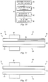
- FIG 11 shows a device of another therapy that could be applied as the therapy in step 42.
- an occlusive balloon is shown generally labeled 46.
- the balloon catheter 52 has a catheter body 54 with a distal end 56, an ultimate distal end 58, a proximal end 60, a central lumen 62, a balloon 64 and a balloon lumen 66.
- the balloon 64 is located a small distance from the ultimate distal end 58 and the central lumen 62 extends from the proximal end of the balloon catheter 52 to the ultimate distal end 58.
- the balloon catheter 52 also has an imaging transducer 14 located at the distal end 56 of the balloon catheter 52.
- the imaging transducer 14 is preferably an IVUS or OCT imaging transducer that is part of an imaging system 2 such as has been described above that allows the user to identify intravascular stenoses.
- the imaging system 2 may also include so-called virtual histology (VH) technology to help the physician recognize and identify the morphology of tissue, particularly plaque associated with a lesion, in vivo (i.e., the location and composition of plaque in the patient's body).
- VH virtual histology
- a characterization application of the IVUS system is adapted to receive and store venous characterization data (e.g., tissue type, etc.) that is subsequently utilized to classify the tissue type of a patient.
- venous characterization data e.g., tissue type, etc.
- a histology correlation is prepared.
- the venous vessel is dissected or cross-sectioned for histology.
- the cross-section is marked, for example with one or more sutures, so that the histology can be correlated to a portion of the IVUS image based on the marker(s).
- the cross-section is then prepared with a fixing and staining process that is well known in the art.
- the staining process allows a trained clinician to identify a tissue type(s), or a chemical(s) found within (e.g., a chemical corresponding to a particular tissue type, etc.). It should be appreciated that the particular method used to identify or characterize the cross-sectional venous vessel is not a limitation of the present invention. Thus, all identification/characterization methods generally known to those skilled in the art are within the spirit and scope of the present invention.
- the identified tissue type or characterization (i.e., characterization data) is then provided to the characterization application for storage and access in future procedures. Accordingly, in some instances the characterization data is stored in a venous tissue characteristic database. It should be appreciated that the data may input to the characterization application and/or database using any suitable input device(s) generally known to those skilled in the art.
- tissue type or characterization include, but are not limited to, fibrous tissues, fibro-lipidic tissues, calcified necrotic tissues, calcific tissues, collagen compositions, cholesterol, thrombus, compositional structures (e.g., the lumen, the vessel wall, the medial-adventitial boundary, etc.) and all other identifiable characteristics generally known to those skilled in the art.
- One method of populating the venous tissue characteristic database begins with collecting IVUS data (i.e., RF backscatter data) from a portion of a venous vessel. This data is then used to create an IVUS image at step. The interrogated portion of the venous vessel is cross-sectioned and a tissue type (or a characterization thereof) is identified. This information (i.e., characterization data) is then transmitted to a computing device (or the equivalent thereof). An image of the cross-sectioned vascular object is created and at least one region of interest is identified (e.g., by an operator). This image is then morphed, if needed, to substantially match it to the initially obtained IVUS image.
- IVUS data i.e., RF backscatter data
- This may include identifying at least one landmark and applying at least one algorithm (e.g., a morphometric algorithm, a thin plate spline deformation technique, etc.).
- the region(s) of interest is mapped to the IVUS image and associated IVUS data is identified.
- Spectral analysis is then performed on the associated IVUS data, and at least one parameter is identified.
- the at least one parameter and the characterization data are then stored in the database.
- the at least one parameter is stored such that it is linked to the characterization data. It should be appreciated that the order in which these steps are presented is not intended to limit the present invention. Thus, for example, creating an IVUS image after the vascular object is cross-sectioned is within the scope of the present invention.
- tissue type or characteristic can be automatically and accurately identified if the acquired parameters substantially match parameters stored in the database.
- the characterization application of the IVUS system can then be utilized to receive IVUS data, determine parameters related thereto, and use the venous tissue characteristic parameters stored in the database (i.e., histology data) to identify tissue type(s) or characterization(s) thereof.
- the central lumen 62 of the balloon catheter 52 is attached to a source of suction (not shown) at the proximal end 60 of the balloon catheter 52 by means well understood in the art.
- the distal end 56 of the balloon catheter 52 is advanced in the patient's vein of interest past the lesion but where the balloon 64 is downstream of the lesion.
- the balloon 64 is inflated so that it occludes blood flow in the vein.
- the ultimate distal end 58 is located near the lesion.
- the suction is activates so that suction is applied at the ultimate distal end 58. Because the ultimate distal end 58 is located in close proximity of the lesion, thrombus will be subject to the suction force and sucked into the balloon catheter to travel through the central lumen 62 to be removed through the proximal end 60.
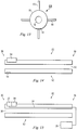
- FIG. 12 and 13 Another device of another therapy that could be applied as the therapy in step 42 is shown in Figures 12 and 13 .
- a cutting catheter 68 is shown.
- the cutting catheter 68 has a catheter body 70 with a distal end 72, a proximal end 74, a central lumen 76 through which a guide wire (not shown) may be passed and an outer surface 78.
- the cutting catheter 68 includes, but is not limited to, the types disclosed in US Patent Nos. 5421338 entitled "Acoustic Imaging Catheter and the Like" issued to Robert J. Crowley, Mark A. Hamm and Charles D.
- the cutting catheter 68 preferably has an imaging transducer 14 as part of an imaging system 2 located at its distal end 72. Further, the cutting catheter 68 includes cutting blades 80 located on its outer surface 78 near the distal end 72.
- the cutting blades 80 are preferably anywhere from about 0.5 - 2 mm in depth and from about 5 - 20 mm in length although other lengths can be used depending on the vessel that the cutting catheter 68 will be used in.
- the cutting blades 80 can be spaced radially around the outer surface 78 for cutting or scoring circumferentially or can be spaced on one side of the catheter 68 for selective cutting or scoring.
- the cutting blades 80 contact and score the fibrin of the lesion, particularly thrombus that is attached to and incorporated into the vein wall, thereby creating space that allows the rest of the fibrin to be compressed into a larger opening by the opening of the balloon.
- FIG. 14 Yet another device of another therapy that could be applied as the therapy in step 42 is shown in Figures 14 .
- an ablation catheter 82 is shown.
- Such ablation catheter 82 delivers ablation energy through laser, so-called Radio Frequency Ablation or "RFA", both ablative and thermal, cryoablation, ultrasound, microwave or other energy sources.
- RFID Radio Frequency Ablation
- Examples of such ablation catheters 80 include, but are not limited to, those disclosed in US Patent Nos.
- RF ablation systems include, but are not limited to ablative systems such as that sold by Halt Medical Inc.
- the ablation catheter 82 has a catheter body 84 with a distal end 86, a proximal end 88, a central lumen 90 through which a guide wire (not shown) may be passed, an outer surface 92 and ablation system 94.
- the ablation catheter 82 preferably has, but is not required to have, an imaging transducer 14 as part of an imaging system 2 located at its distal end 86.
- the imaging system 2 helps the physician to locate the lesion.
- the ablation therapy is applied by the ablation system 94 to ablate the lesion.
- the imaging system 2 may be particularly useful in helping the physician apply the ablation therapy and assess the extent of such ablation.
- the imaging system 2 is an OCT system and ablation system 94 is combined with the distal optics 22 of the imaging system 2.
- the ablation provided by the ablation system 94 is laser ablation that is supplied to the ablation system 94 from the same light source 20 used by the OCT system to produce the OCT images, typically through optical fibers 24 connecting the light source 20 to the distal optics 22.
- the light source 20 used to produce the OCT images would typically be located remotely from the distal optics 22 supplied light via the optical fibers 24, it is within the scope of the present invention in all embodiments for the light source 20 to be located in close proximity to the distal optics 22.
- this same light source 20 provides not only the light needed to produce the OCT images but also the laser light used by the ablation system 94 to do the ablation.
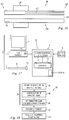
- a therapeutic agent deliver catheter 96 delivers a therapeutic agent to the lesion to dissolve fibrin or thrombus present at or causing the lesion or otherwise treat the lesion.
- therapeutic agent delivery catheters 92 include, but are not limited to, those disclosed in US Pat. Nos. 5135516 entitled "Lubricious Antithrombogenic Catheters, Guidewires and Coatings” issued to Ronald Sahatjian and Kurt Amplatz on August 4, 1992; 6535764 entitled "Gastric treatment and diagnosis device and method” issued to Mir A. Imran, Olivier K. Colliou, Ted W.
- therapeutic agents that may be delivered to the lesion include, but are not limited to tissue plasminogen activator, urokinase, streptokinase, collagenace, hepranoids and any other fibrinolytic or direct anti-thrombin drug.
- the therapeutic agent deliver catheter 96 has a catheter body 98 with a distal end 100, a proximal end 102, a central lumen 104 through which a guide wire (not shown) may be passed, an outer surface 106, a balloon 108 and a balloon lumen 110.
- the therapeutic agent deliver catheter 96 preferably has, but is not required to have, an imaging transducer 14 as part of an imaging system 2 located at its distal end 100.
- the balloon 108 is inflated and deflated via the balloon lumen 110 as is well understood in the art.
- the balloon 108 delivers the therapeutic agent.
- the therapeutic agent may coat the balloon 108 so that as the balloon is inflated, the therapeutic agent is brought into contact with a lesion so that the therapeutic agent may be applied to the lesion.
- the balloon 108 may be porous or have slits or other fenestrations to allow therapeutic agent present within the balloon to pass through the pores, slits or other fenestrations to come into contact with the tissue at or near a stenosis.
- the imaging system 2 if present, helps the physician to locate the lesion. Once the therapeutic agent deliver catheter 96 is located at the lesion, the therapeutic agent to is applied to the lesion as described above.
- the imaging system 2 may be particularly useful in helping the physician apply the therapeutic agent and assess the extent of such therapy.
- the therapeutic method 30 is also typically run as software on a computing device 8 and thus the combination of the computing device 8 and the therapeutic methods 24, as described above, becomes the therapeutic device 32 ( Figure 17 ).
- the therapeutic device 32 is preferably operated on a computing device 8
- the therapeutic device 32 may also be operated separately on any system having sufficient computing capability to perform the steps of the therapeutic method 30, and diagnostic method 26 if present, and be operatively to the console 4, computing device 8, characterization application 12 or database 10 or any combination of these.
- the therapeutic device 32 may also be an application specific device or hardwired specifically to perform the functions described herein.
- the therapeutic device 32 acts according to algorithms described above in connection with the therapeutic method 30.
- the therapeutic device 32 may be implemented on or may be an adjunct to an imaging system 2.
- the imaging system 2 may take the form of an intravascular ultrasound (IVUS) imaging system 2 as described above including a console 4, IVUS catheter 6, a computing device 8 comprising a database 10 and a characterization application 12 electrically connected to the database 10 and typically run on the computing device 8.
- IVUS intravascular ultrasound
- the imaging system 2 may take the form of an optical coherence tomography (OCT) system that also includes a console 4, OCT catheter 6, a computing device 8 comprising a database 10 and a characterization application 12 electrically connected to the database 10 and typically run on the computing device 8.
- OCT optical coherence tomography
- the therapy delivery device 26 such as the balloon catheter 52, cutting catheter 68, ablation catheter 82 and therapeutic agent deliver catheter 96 included an imaging transducer 14 as part of an imaging system 2 that allowed the therapy delivery device to be located with respect to the lesion so that the therapy could be most effectively applied.
- an imaging transducer 14 as part of an imaging system 2, typically near the distal end of such therapy delivery devices, to also allow the therapy delivery device to be located with respect to the lesion so that the therapy can be most effectively applied.
- embolic protection it may also be useful to apply embolic protection to prevent pieces of fibrin, thrombus or other tissue dislodged by the application of therapy in step 42 from moving downstream with the blood flow.
- IJV internal jugular veins
- AZV azygous veins
- embolic protection such as the SpiderFX® Embolic Protection Device made and sold by ev3, Inc. of Madison, Minnesota and the FilterWire EZTM Embolic Protection System for SVG's made and sold by Boston Scientific, Inc. of Natick, Massachusetts may help prevent the occurrence of such embolisms.
- the therapeutic method 30 shown in Figure 18 includes a step 114 so that the program passes from step 42 to step 114.
- step 114 intraluminal abnormalities are assessed to see if the therapy of step 42 worked.
- a preferred way to assess the intraluminal abnormalities is to reintroduce the diagnostic catheter over the same exchange wire used as part of the therapy of step 42 to perform a post-therapy selective venogram and assess the residual stenosis of the lesion.
- step 116 the pressure gradient across the stenosis is assessed as described in step 38 to determine, post-therapy, whether adequate blood flow is now present as a result of the therapy of step 42.
- this assessment of the nature of the stenotic lesion post-therapy is preferably accomplished as step 118 by applying IVUS or OCT or both IVUS and OCT to the area of the applied therapy in step 42.
- a significant stenosis is defined as luminal reduction greater than 50% of normal venous diameter as obtained during step 36 or a significant flow disruption associated with an intraluminal abnormality noted during the IVUS or OCT imaging at step 38. Consequently, a successful therapy occurs when the stenosis now has a luminal reduction less than 50% of normal venous diameter as obtained during step 36 with no significant flow disruption.
- therapeutic methods 30 have been described above in connection with a step 42 with may optionally include either step 116 or 118, an alternate therapeutic method 30 may also include both step 116 and 118 performed in any order.
- step 42 additional therapy of any of the types described above may be applied as shown in Figure 21 .
- the desired reduction of the stenosis is such that the residual stenosis is less than 75% of the normal proximal diameter of the stenotic vein or that a pressure gradient exceeding 1mm Hg is no longer observed. Additional therapy will be performed if these therapy goals are not observed. Consequently, if the therapy goals are not met, the program passes from step 42 to step 120 where step 120 is the application of an additional therapy.
- the therapy of step 120 may be either the reapplication of the same therapy that was applied in step 42 or the application of an entirely new therapy of the types described above.
- Steps 114, 116 may also be applied as described in connection with step 42 or applied singly or in combination to step 120.
- step 42 or step 120 additional therapy may also be performed at step 122 on all affected veins using the same techniques described above in step 42 if there are additional affected veins with significant stenoses in the IJV or AZV. Further, additional therapies or the reapplication of any of the therapies listed above in connection with steps 42 and 120 may be applied to these additional affected veins.
- the present invention has been described in connection with many different diagnostic and therapeutic methods and devices.
- imaging systems 2 described herein have been either intravascular ultrasound (IVUS) systems or optical coherence tomography (OCT) systems, any other system capable of producing an image of a patient's vasculature may be used as the imaging system 2.
- IVUS intravascular ultrasound
- OCT optical coherence tomography
- any other system capable of producing an image of a patient's vasculature may be used as the imaging system 2.
- the inventions described herein have been described as being directed to primarily to the diagnosis and treatment of MS, it is also within the scope of the invention to be directed at diagnosing and treating deep vein thrombosis (DVT) and pulmonary embolisms.
- DVD deep vein thrombosis
- pulmonary embolisms To diagnose and treat these maladies, the devices and methods described herein are placed in the peripheral veins or pulmonary vessels, respectively, instead of in the IJV or AZV.
- embodiments of the invention described herein that remove thrombus from the vessel wall may be particularly useful.
Landscapes
- Health & Medical Sciences (AREA)
- Life Sciences & Earth Sciences (AREA)
- Engineering & Computer Science (AREA)
- Public Health (AREA)
- Medical Informatics (AREA)
- Heart & Thoracic Surgery (AREA)
- Biomedical Technology (AREA)
- General Health & Medical Sciences (AREA)
- Animal Behavior & Ethology (AREA)
- Veterinary Medicine (AREA)
- Surgery (AREA)
- Physics & Mathematics (AREA)
- Biophysics (AREA)
- Molecular Biology (AREA)
- Pathology (AREA)
- Nuclear Medicine, Radiotherapy & Molecular Imaging (AREA)
- Radiology & Medical Imaging (AREA)
- Vascular Medicine (AREA)
- Physiology (AREA)
- Hematology (AREA)
- Cardiology (AREA)
- Computer Vision & Pattern Recognition (AREA)
- Optics & Photonics (AREA)
- Pulmonology (AREA)
- Anesthesiology (AREA)
- Child & Adolescent Psychology (AREA)
- Otolaryngology (AREA)
- Electromagnetism (AREA)
- Dentistry (AREA)
- Oral & Maxillofacial Surgery (AREA)
- High Energy & Nuclear Physics (AREA)
- Primary Health Care (AREA)
- Epidemiology (AREA)
- Databases & Information Systems (AREA)
- Data Mining & Analysis (AREA)
- Ultra Sonic Daignosis Equipment (AREA)
- Surgical Instruments (AREA)
- Measuring Pulse, Heart Rate, Blood Pressure Or Blood Flow (AREA)
- Endoscopes (AREA)
- Laser Surgery Devices (AREA)
Description
- This invention relates to improved devices for treating CCSVI (chronic cerebrospinal venous insufficiency) in patients with multiple sclerosis or other diseases that are due to or exacerbated by obstructions to blood flow and, more particularly, to devices for identifying patients particularly likely to benefit from the delivery of one or more therapies to treat such patients and devices for delivering such therapies.
- Multiple sclerosis (MS) is an inflammatory disease of the nervous system where the fatty myelin sheaths around the axons of the brain and spinal column are damaged. As a result of this damage, the ability of nerve cells in the brain and spinal cord to communicate with each other is compromised. Almost any neurological symptom, including physical and cognitive disability, can appear with the disease. MS affects more than 350,000 people in the United States and 2.5 million worldwide. In the United States, prevalence estimates are approximately 90 per 100,000 people.
- Beginning with the first description of the anatomy associated with MS by Jean-Martin Charcot in 1868, MS plaques associated with MS have been known to be centered or located around veins. Further, it has been recently shown that MS is significantly correlated with a condition called chronic cerebrospinal venous insufficiency (CCSVI). CCSVI is a condition where people have obstructed blood flow in the veins that drain the central nervous system (the brain and spinal cord) and is characterized by multiple stenoses of the principal pathways of extracranial venous drainage, the internal jugular veins (IJV) and the azygous veins (AZV), with opening of collaterals, clearly demonstrated by means of selective venography and magnetic resonance venography (MRV).
- Stenosis literally means a "narrowing." Here "stenosis" or its plural "stenoses" is an abnormal narrowing of the vein that restricts blood flow. This abnormal narrowing may be the result of many things. For example, the abnormal narrowing maybe the result of a collapse of the vein, twisting of the vein, ring-like narrowings in the vein and other similar obstructions. Further, the abnormal narrowing may be the result of severe venous problems including veins that are partially closed, underdeveloped, minimally formed or almost entirely missing. In addition, an abnormal or defective valve, septum, flap or membrane may narrow, blocks or inhibit blood flow through the veins. Finally, the build up of plaque, fibrin or thrombus may cause an abnormal narrowing of the vein. With respect to MS, a consequence of a stenosis in a vein leads to problems with normal or efficient blood drainage from the brain and spine back to the heart.
- Intravascular ultrasound ("IVUS") combined with a technique called virtual histology ("VH") has been particularly successful in recognizing the morphology of atherosclerotic plaque in vivo (i.e., the location and composition of plaque in the patient's body). Current developments are underway to also be able to recognize thrombus in vivo.
Figure 1 illustrates a typicalintravascular imaging system 2 that uses intravascular ultrasound (IVUS).Figure 2 illustrates a typicalintravascular imaging system 2 that uses optical coherence imaging (OCT). - An example of an IVUS system is the s5i™ Imaging System sold by Volcano Corporation of San Diego, California. Examples of OCT imaging systems include, but are not limited to, those disclosed in
US Patent No. 5724978 issued March 10, 1998 entitled "Enhanced accuracy of three-dimensional intraluminal ultrasound (ILUS) image reconstruction" with Harm Tenhoff as inventor,US Published Patent Application Nos. 20070106155 entitled "System and method for reducing angular geometric distortion in an imaging device" with John W. Goodnow and Paul Magnin as inventors and published on May 10, 2007,20080287801 entitled "IMAGING DEVICE IMAGING SYSTEM AND METHODS OF IMAGING" with Russell W Bowden, Tse Chen Fong, John W. Goodnow, Paul Magnin and David G. Miller and published on November 20, 2008,2004693980 entitled "REAL TIME SD-OCT WITH DISTRIBUTED ACQUISITION AND PROCESSING" with Nathanial J. Kemp, Austin Broderick McElroy and Joseph P. Piercy as inventors and published on April 9, 2009,20080119701 entitled "ANALYTE SENSOR METHOD AND APPARATUS" with Paul Castella, Nathaniel J. Kemp and Thomas E. Milner as inventors and published on May 22, 2008,2004618393 entitled "CATHETER FOR IN VIVO IMAGING" with Larry Dick, Thomas E. Milner and Daniel D. Sims as inventors and published on January 15, 2009,2004646295 entitled "APPARATUS AND METHODS FOR UNIFORM SAMPLE CLOCKING" issued to Nathaniel J. Kemp, Roman Kuranov, Austin Broderick McElroy and Thomas E. Milner as inventors and published on February 19, 2009,2004884749 entitled "OCT Combining Probes and Integrated Systems" with Dale C. Flanders and Bartley C. Johnson as inventors and published on November 19, 2009 and WIPO Published Patent Application No.WO200483635 -
Such imaging systems 2 may also include systems capable of identifying the makeup of the tissue and material of a patient's vasculature including so called virtual histology (VH) systems. An example of a VH system is the s5i™ Imaging System with VH capability sold by Volcano Corporation of San Diego, California. Theimaging systems 2 may also include systems for measuring the flow of blood in a patient's vasculature. An example of such a blood flow measurement system is a color-Doppler ultrasound imaging system sold under the brand name of Chromaflow® by Volcano Corporation of San Diego California. - In an
exemplary imaging system 2, an intra-vascular ultrasound (IVUS)console 4 is electrically connected to anIVUS catheter 6 and used to acquire RF backscattered data (i.e., IVUS data) from a blood vessel. The IVUSconsole 4 typically includes acomputing device 8 comprising adatabase 10 and acharacterization application 12 electrically connected to thedatabase 10 and adapted to receive IVUS data from theIVUS console 4 or directly from atransducer 14. Specifically, atransducer 14 is attached to the end of thecatheter 6 and is carefully maneuvered through a patient's arteries to a point of interest along the artery. The transducer is then pulsed to acquire high-frequency sonic echoes or backscattered signals reflected from the tissue of the vascular object. Because different types and densities of tissue absorb and reflect the ultrasound pulse differently, the reflected data (i.e., IVUS data) is used to image the vascular object. In other words, the IVUS data can be used (e.g., by the IVUSconsole 4 or a separate computing device 8) to create an IVUS image. - An exemplary IVUS image 16 is shown in
FIG. 2 , where the light and dark regions indicate different tissue types and/or densities. It should be appreciated that the IVUSconsole 4 depicted herein is not limited to any particular type of IVUS console, and includes all ultrasonic devices known to those skilled in the art (e.g., a Revolution® or EagleEye® IVUS catheter used in conjunction with an s5™ IVUS imaging system, all of which are sold by Volcano Corporation of San Diego, California). It should further be appreciated that the IVUScatheter 6 depicted herein is not limited to any particular type of catheter, and includes all ultrasonic catheters known to those skilled in the art. Thus, for example, a catheter having a single transducer (e.g., adapted for rotation) or an array of transducers (e.g., circumferentially positioned around the catheter or longitudinally along the catheter 6) can be used with thetypical imaging system 2. - It should be appreciated that the
database 10 depicted herein includes, but is not limited to, RAM, cache memory, flash memory, magnetic disks, optical disks, removable disks, SCSI disks, IDE hard drives, tape drives and all other types of data storage devices (and combinations thereof, such as RAID devices) generally known to those skilled in the art. It should further be appreciated that thecharacterization application 12, as depicted and discussed herein, may exist as a single application or as multiple applications, locally and/or remotely stored. It should also be appreciated that the number and location of the components depicted inFIG. 1 do not limit atypical imaging system 2 but are merely provided to illustrate atypical imaging system 2. Thus, for example, acomputing device 8 having a plurality ofdatabases 10 or a remotely located characterization application 12 (either in part or in whole) or any combination of these may also be found in atypical imaging system 2. - In one embodiment of a
typical imaging system 2, thecharacterization application 12 is adapted to receive and store characterization data (e.g., tissue type, etc.). The characterization data was determined prior to using the tissue -characterization system 2 as follows. After a specimen vascular object has been interrogated (e.g., IVUS data has been collected), a histology correlation is prepared. In other words, the specimen vascular object is dissected or cross-sectioned for histology. In one method of producing characterization data, the cross-section is previously marked, for example with a suture, so that the histology can be corresponded to a portion of the IVUS image. The cross-section is then prepared with a fixing and staining process that is well known in the art. The staining process allows a clinician to identify a tissue type(s), or a chemical(s) found within (e.g., a chemical corresponding to a particular tissue type, etc.). The identified tissue type or types is then correlated to the IVUS data as will be explained below. - Where the
imaging system 2 is or includes an OCT system, theimaging system 2 typically includes alight source 20 that produces light of a desired frequency and with other desired characteristics well understood in the art that is ultimately directed from thecatheter 6 to the patient's vasculature bydistal optics 22. A typicalOCT imaging system 2 has thelight source 20 located remotely from or nearby thecatheter 6.Optical fibers 24 carry the light from thelight source 20 to thedistal optics 22. - Medical diagnostic ultrasound methods and systems for automated flow analysis are provided in
US6503202 . Multiple cross-sectional areas along a vessel are determined automatically. A processor locates an abnormality as a function of the multiple cross-sectional areas, such as identifying a cross-sectional area that is a threshold amount less than an average cross-sectional area. The abnormal area is highlighted on the display to assist with medical diagnosis. For the carotid artery, the interior and exterior branches are labeled to assist medical diagnosis. The two branches are automatically identified. The branch associated with additional small branches is identified as the exterior carotid. - It should be appreciated that there may be many methods used to identify or characterize the cross-sectional object as is well understood in the art besides the method just described. Thus, any identification/characterization method generally known to those skilled in the art may be used to characterize tissue. The identified tissue type or characterization (i.e., characterization data) is then provided to the
characterization application 12. In one embodiment, as shown inFIG. 1 , the characterization data is provided via aninput device 18 electrically connected to thecomputing device 8. The characterization data is preferably then stored in thedatabase 10. It should be appreciated that the input device depicted herein includes, but is not limited to, a keyboard, a mouse, a scanner and all other data-gathering and/or data-entry devices generally known to those skilled in the art. It should further be appreciated that the term tissue type or characterization, as these terms are used herein, include, but are not limited to, fibrous tissues, fibro-lipidic tissues, calcified necrotic tissues, necrotic core, calcific tissues, collagen compositions, cholesterol, thrombus, compositional structures (e.g., the lumen, the vessel wall, the medial-adventitial boundary, etc.) and all other identifiable characteristics generally known to those skilled in the art. - In one method of characterizing tissue, the characterization application is adapted to create a histology image and to identify at least one corresponding region on an IVUS image. Specifically, digitized data is provided to the characterization application (e.g., via the input device 18), where the digitized data corresponds to the cross-sectioned vascular object. The digitized data is then used to create a histology image (i.e., a digital image or outline that substantially corresponds to the vascular object). A region of interest (ROI) on the histology image can then be identified by the operator. Preferably, the ROI is characterized by the characterization data, as previously provided, and may be the entire histology image or a portion thereof. The characterization application is then adapted to identify a corresponding region (e.g., x,y coordinates, etc.) on the IVUS image. A system for identifying and treating obstructions is known from document
WO 2008/088579 A2 . - In view of the foregoing, what is needed is an effective device for assisting a healthcare provider to identify patients whose MS, or MS symptoms, are likely exacerbated if not caused, at least in part, by blockages of one or more of the patient's internal jugular veins (IJV) or azygous veins (AZV) and for those patients, devices for applying one or more therapies to the blockages in the patient's IJV or AZV veins.
- The invention relates to a multiple sclerosis, deep vein thrombosis, and/or pulmonary embolism therapeutic system as defined by claim 1. Preferred embodiments are described by the dependent claims.
- Methods and devices are disclosed that diagnose and treat MS or MS symptoms. In one series of embodiments, the invention consists ofdevices for identifying patients whose MS, or MS symptoms, are likely exacerbated if not caused, at least in part, by blockages of one or more of the patient's internal jugular veins (IJV) or azygous veins (AZV). The stenoses in the patient's affected veins are identified. The nature of such lesions and whether there is a significant disruption of blood pressure or flow, or both, is ascertained.
- In another series of embodiments, the invention consists of devices for applying one or more therapies to the blockages in the patient's IJV or AZV veins. In preferred embodiments of such devices, therapy is delivered to open the stenosis causing such blockages.
- It is an object of this invention in one or more embodiments to identify blockages of a patient's vasculature or flow limiting or interrupting structures that have likely exacerbated if not caused, at least in part, MS, or MS symptoms, in that patient.
- It is an object of this invention in one or more embodiments to treat blockages of a patient's vasculature or flow limiting or interrupting structures that have likely exacerbated if not caused, at least in part, MS, or MS symptoms, in that patient.
- The invention will be described hereafter in detail with particular reference to the drawings. Throughout this description, like elements, in whatever embodiment described, refer to common elements wherever referred to and referenced by the same reference number. The characteristics, attributes, functions, interrelations ascribed to a particular element in one location apply to that element when referred to by the same reference number in another location unless specifically stated otherwise.
-
-
Figure 1 is a schematic view of a typical intravascular ultrasound (IVUS) imaging system. -
Figure 2 is a schematic view of a typical intravascular optical coherence tomography (OCT) imaging system. -
Figure 3 is a flow chart of an embodiment of the diagnostic method not being part of the present invention. -
Figure 4 is a flow chart of another embodiment of the diagnostic method not being part of the present invention. -
Figure 5 is a flow chart of another embodiment of the diagnostic method not being part of the present invention. -
Figure 6 is a flow chart of another embodiment of the diagnostic method not being part the present invention. -
Figure 7 is a schematic view of an embodiment of the diagnostic device of the present invention. -
Figure 8 is a flow chart of an embodiment of the therapeutic method not being part of the present invention. -
Figure 9 is a flow chart of an alternate embodiment of the therapeutic method not being part of the present invention. -
Figure 10 is a flow chart of an embodiment of the therapy delivered as the therapeutic method not being part of the present invention. -
Figure 11 is a side cross-sectional schematic view of a device of a therapy that could be applied as the therapy of the any of the therapeutic methods. -
Figure 12 is a side cross-sectional schematic view of a device of a therapy that could be applied as the therapy of the any of the therapeutic methods. -
Figure 13 is an end schematic view of the device ofFigure 12 . -
Figure 14 is a side cross-sectional schematic view of a device of a therapy that could be applied as the therapy of the any of the therapeutic methods. -
Figure 15 is a side cross-sectional schematic view of an alternate embodiment of the device ofFigure 14 . -
Figure 16 is a side cross-sectional schematic view of an embodiment of a therapeutic catheter according to an embodiment
of the present invention. -
Figure 17 is a schematic view of an embodiment of the therapeutic device of the present invention. -
Figure 18 is a flow chart of another embodiment of the therapeutic method not being part of the present invention. -
Figure 19 is a flow chart of another embodiment of the therapeutic method not being part of the present invention. -
Figure 20 is a flow chart of another embodiment of the therapeutic method not being part of the present invention. -
Figure 21 is a flow chart of another embodiment of the therapeutic method not being part of the present invention. -
Figure 22 is a flow chart of another embodiment of the therapeutic method not being part of the present invention. - The present invention is defined by independent claim 1. Below are disclosed a Multiple
Sclerosis Diagnostic Method 26, its corresponding Multiple Sclerosis Diagnostic Device 28, a Multiple Sclerosis Treatment Diagnostic andTreatment Method 30 and its corresponding Multiple Sclerosis Treatment Diagnostic andTreatment Device 32. Thediagnostic method 26 and diagnostic device 28 determine whether a patient's physiology indicates that the patient has a form of MS, or MS symptoms, that are exacerbated if not caused, at least in part, by blockages or flow limiting or interrupting structures of one or more of the patient's internal jugular veins (IJV) or azygous veins (AZV). Thetherapeutic method 30 andtherapeutic device 32 provide one or more therapies to treat the patient's MS, or MS symptoms. In embodiments not being part of the invention, thetherapeutic method 30 includes adiagnostic method 26 and, in addition, applies a therapy to treat the MS, or MS symptoms. According to the invention, thetherapeutic device 32 includes a diagnostic device 28 that, in addition, also applies a therapy to treat the MS, or MS symptoms. Examples of flow limiting or interrupting structures include, but are not limited to, physiological defects, stenoses and faulty valves. - Referring to the Figures, the diagnostic method is shown in the Figures generally referred to by the
reference number 26. Thediagnostic method 26, in preferred embodiments not being part of the present invention and described hereafter, acts according to algorithms having the following steps, as set out in the flow charts ofFigures 3-6 . - In the
diagnostic method 26 shown inFigure 3 , the diagnostic method begins atstep 36 where venous outflow obstruction sites are identified. A preferred method of indentifying these obstruction sites is by sequentially accessing the AZV entry into the superior vena cava and the two Common Jugular veins by selective venography at each of these sites to confirm or exclude a significant stenosis or flow disruption. Venography, which is also called phlebography, involves taking an x-ray of the veins, a venogram, after a special dye is injected via a catheter into the vein of interest. Typically, the dye is injected constantly via a catheter. As a result, a venography is an invasive procedure. - Although venography has been a preferred method for selecting sites having significant stenosis or flow disruption, ultrasonography, including duplex ultrasonography, could also be used in the alternative or in addition to identify obstructed outflow sites. Ultrasonography incorporates two elements:
- 1) Grayscale Ultrasound (e.g., from an IVUS imaging system 2) is used to visualize the structure or architecture of the vein to identify stenoses (cross-sectional narrowing of the vein);
- 2) Color-Doppler ultrasound imaging (e.g., from Volcano Corporation) is then used to visualize the flow or movement of a blood within the vein;
and typically presents both displays on the same screen ("duplex") to facilitate interpretation. Where ultrasonography is used, a stenosis having cross-sectional narrowing greater than about 70% is considered worthy of treatment as are blood flow velocities greater than 250 cm/sec (which also indicate a region of narrowing or resistance produced by a major stenosis). Ultrasonography can also be enhanced by tissue characterization such as the virtual histology characterization described above, for example, as part of the s5i™ Imaging System with VH capability sold by Volcano Corporation of San Diego, California. - Besides venography and ultrasonography, transcutaneous echography applied to an accessible section of the IJV could also be used to identify venous outflow obstruction sites and to confirm or exclude a significant stenosis or flow disruption at those sites. Further, in an embodiment of the invention, radionuclides that bind to proteins specific to fibrin, such as radionuclides bound to insulin-like growth factor (IGF) binding proteins (IGFBPs) are applied intravenously, preferably near where an obstruction is believed to be located, or orally. Then, external detectors such as gamma cameras capture and form images from the detected radiation emitted by the radionuclides that are bound to the proteins of the fibrin. This allows the areas of venous outflow obstruction caused by the buildup of thrombus to be located and to confirm or exclude a significant stenosis or flow disruption at the site. These last two methods have the desirable characteristic of being non-invasive.
- In a modification of the invention above where something is bound to proteins specific to fibrin, plasmin, other plasmids or any like substance that dissolves fibrin is bound to the same IGFBP that contains the radionuclide or to an entirely different IGFBP and then delivered to the site of the fibrin as described above. The plasmin, plasmid or other substance that dissolves fibrin in whatever form may be self-activated (i.e., it is active upon delivery) or may be activated by the exposure to either a specific light frequency or by ultrasound at a specific frequency or any like energy source delivered either intravascularly or noninvasively. Where these substances are active by a specific light frequency or by ultrasound at a specific frequency, the light or ultrasound or both may be delivered via the
distal optics 22 ortransducer 14, respectively. - Once the venous outflow obstruction sites have been identified by whatever method, the method passes to step 38. In
step 38, the nature of the stenotic lesion is assessed. This assessment is preferably accomplished by applying animaging system 2 such as an IVUS or OCT system or a system having both IVUS and OCT or applying both IVUS and OCT imaging to suspected areas of narrowing or flow disruption to identify intraluminal abnormalities including webs, flaps, inverted or incompetent valves and membranes as well as stenoses caused by plaque or the buildup of fibrin or thrombus. Here, a significant stenosis, of whatever kind, is defined as luminal reduction greater than 50% of the normal venous diameter near the stenosis as obtained duringstep 36 or a significant flow disruption associated with an intraluminal abnormality noted during the IVUS or OCT imaging of thisstep 38. Both IVUS and OCT will provide vessel information whereby vessel circumference measurements can be made. This will allow the physician to check the lumen narrowing to determine whether such narrowing is significant as defined above (i.e., cross-sectional narrowing greater than about 70% or blood flow velocities greater than 250 cm/sec). In a preferred embodiment of the invention, software is provided on theimaging system 2 to correlate these measurements. Once IVUS or OCT or both IVUS and OCT has been used to assess the nature of the stenotic lesion, the method passes to step 40. - In
step 40, the pressure gradient across the stenosis (as compared to the superior vena cava) is determined. This pressure gradient is preferably determined using either a manometer, pressure wire or any other blood pressure measuring device if the suspected significant venous stenosis/intraluminal abnormality is confirmed by any of the methods ofstep 38. Examples of pressure wires are the PrimeWire PRESTIGE™ guide wire, PrimeWire® guide wire and the ComboWire® XT guide wire all made and sold by Volcano Corporation of San Diego, California. A pressure gradient larger than 1-2mm Hg may indicate the presence of a significant stenosis. Information on the pressure gradient is preferably but not required to be communicated to the healthcare provider. The communication in thisstep 40 may take the form of a message displayed onconsole 4, the modifying of an image of a vascular structure displayed on theconsole 4 such as by appending a text or color indicator that the patient's physiology at that location on the vessel is such that the patient's pressure gradient exceeds the targeted amount, the communication of the parameter values themselves separately or by any other means well within the skill of one skilled in the art to communicate such values. - In the
diagnostic method 26 described above, the listed steps 36 - 40 were performed in the order given. However, it is within the scope of the present disclosure forsteps Figure 4 , thediagnostic method 26 has the form of the steps above performed in the following sequential order: - Step 36: Indentify venous outflow obstruction sites;
- Step 40: Determine pressure gradient across the stenosis; and
- Step 38: Assess the nature of the stenotic lesion.
- Further, the method shown in
Figure 3 could be simplified so that either step 38 orstep 40 is done without doing the other so that the method takes the following forms, shown inFigures 5 and 6 , respectively, of the steps above performed in the following sequential order: - Step 36: Indentify venous outflow obstruction sites; and
- Step 38: Assess the nature of the stenotic lesion.
and, - Step 36: Indentify venous outflow obstruction sites; and
- Step 40: Determine pressure gradient across the stenosis.
- As mentioned above, the
diagnostic method 26 in all forms assesses whether a patient has a form of MS, or MS symptoms, that are likely amenable to treatment by a therapy that is directed to the stenosis in the patient's vein and, as a result, has diagnostic value as a diagnostic tool. This diagnostic value occurs in all the embodiments of thediagnostic method 26 described above. - The
diagnostic method 26 is typically run as software on acomputing device 8 and thus the combination of thecomputing device 8 and thediagnostic methods 20, as described above, becomes the diagnostic device 28.Figure 7 shows an embodiment of the diagnostic device 28 where the steps 36 - 38 are performed on thecomputing device 8. Although the diagnostic device 28 is preferably operated on acomputing device 8, the diagnostic device 28 may also be operated separately on any system having sufficient computing capability to perform the steps of thediagnostic method 26 and be operatively connected to theconsole 4,computing device 8,characterization application 12 ordatabase 10 or any combination of these. In addition, the diagnostic device 28 may also be an application specific device or hardwired specifically to perform the functions described herein. - The diagnostic device 28, in preferred embodiments, acts according to algorithms described above in connection with the
diagnostic method 26. The diagnostic device 28 may be implemented on or may be an adjunct to animaging system 2. Theimaging system 2 may take the form of an intravascular ultrasound (IVUS)imaging system 2 as described above including aconsole 4,IVUS catheter 6, acomputing device 8 comprising adatabase 10 and acharacterization application 12 electrically connected to thedatabase 10 and typically run on thecomputing device 8. Alternately or in addition, theimaging system 2 may take the form of an optical coherence tomography (OCT) system that also includes aconsole 4,OCT catheter 6, acomputing device 8 comprising adatabase 10 and acharacterization application 12 electrically connected to thedatabase 10 and typically run on thecomputing device 8. - Although IVUS and OCT systems singly or in combination have been described as the
imaging system 2, any imaging system that obtains images of the patient's vascular may be used. Suchalternate imaging systems 2 will also typically include aconsole 4, acatheter 6 appropriate for thatimaging system 2, acomputing device 8 comprising adatabase 10 and acharacterization application 12 electrically connected to thedatabase 10 and typically run on thecomputing device 8. Regardless of theimaging system 2, the diagnostic device 28 is adapted to communicate, that is both receive and transmit data and information, with theconsole 4 or thecomputing device 8. - Where it has been determined that a patient has a form of MS, or MS symptoms, that are likely amenable to treatment by a therapy that is directed to the stenosis in the patient's vein, it is also desirable to have a tool that, under the physician's control, directs a desired therapy to the stenosis. The
therapeutic method 30 and its correspondingtherapeutic device 32, as described hereafter, is such a tool. - In one embodiment, not being part of the present invention, of the
therapeutic method 30 shown inFigure 8 , thediagnostic method 26 is included as a diagnostic precursor to applying a desired therapy. So, thetherapeutic method 30 includes adiagnostic method 26 that operates as described above in all the variants ofdiagnostic method 26. In another embodiment not being part of the present invention of thetherapeutic method 30 shown inFigure 9 , thetherapeutic method 30 does not include adiagnostic method 26 but includes only the delivery of atherapy 42 as will be described hereafter. - In the embodiment of the
therapeutic method 30 ofFigure 8 including adiagnostic method 26, after the diagnostic steps have been accomplished and it has been determined that a patient's physiology indicates that the patient has a form of MS, or MS symptoms, that are exacerbated if not caused, at least in part, by blockages of one or more of the patient's internal jugular veins (IJV) or azygous veins (AZV), the program passes to step 42. Instep 42, a desired therapy is applied to treat the stenotic lesion. The therapy applied is preferably one that, as a result of the application of the therapy, produces a reduction of the stenosis such that the residual stenosis no longer is flow limiting or that a pressure gradient exceeding 1-2mm Hg is no longer observed or both. - In one embodiment of the
therapeutic method 30, a preferred therapy instep 42 is angioplasty to open or enlarge the troubling stenosis. The angioplasty may be either conventional angioplasty or angioplasty using a cutting or scoring balloon.Figure 10 shows a flow chart of the steps involved in thetherapeutic method 30 to accomplish such an angioplasty procedure. The goal of the angioplasty procedure will be to restore the venous outflow structure to where it is no longer flow limiting, flow disruption is resolved and pressure gradient is minimal. - In
Figure 10 , the angioplasty therapy is begun atstep 44 where the appropriate angioplasty balloon to be used is determined based on measurements previously made such as during a venogram. It is preferable but not required for the balloon to be a non-compliant balloon that will have a nominal inflated diameter of at least 80% of the normal proximal non-stenosed vein. The benefit of using a non-compliant balloon here is to obtain high pressure to increase the opportunity for compression of the obstruction. - The balloon is preferably a one piece balloon. Such a balloon may, but is not required to be, coated with or exuding a drug such as tissue plasminogen activator, urokinase, streptokinase, collagenace, hepranoids and any other fibrinolytic or direct anti-thrombin drug or drugs or antigens or both that may promote more rapid healing of a vessel.
- Further, as mentioned above, the balloon may be a cutting or scoring balloon. A cutting balloon is one that has small blades that are activated (moved outward) by actuation of the balloon. The cutting blades score the fibrin of a lesion, particularly thrombus that is attached to and incorporated into the vein wall, thereby creating space that allows the rest of the fibrin to be compressed into a larger opening by the opening of the balloon. When the appropriate balloon to be used to open the stenosis has been determined, by whatever means, the program then passes to step 46. The scoring balloon is one that scores the plaque circumferentially to dilate the obstructed vessel such as the AngioSculpt Scoring Balloon Catheter made and sold by AngioScore Inc. of Fremont, California.
- At
step 46, the patient is loaded with intravenous weight based load of heparin (50-100U/kg) to confirm an Activated Clotting Time (ACT) of at least 250 as is well understood in the art. After loading the patient with heparin to confirm ACT, the program then passes to step 48. - In
step 48, the balloon is placed at the stenosis and inflated as is well understood in the art. After confirmation of the ACT, an exchange length 0.035" exchange length glide wire is advanced into the proximal vein of interest (before the obstruction) and the non-compliant balloon is placed across the stenosis. The balloon is slowly inflated, for example, with one atmosphere per 30 seconds until reaching nominal pressure (e.g., 8-12 atmospheres) to open the stenosis. The dilated balloon is left in place for a clinically significant time as is well understood in the art. After the balloon has been left in place for a clinically significant time, the method then passes to step 50. - In
step 50, the balloon is deflated and withdrawn. The balloon is preferably deflated at a moderate rate (e.g., one atmosphere per 15 seconds) and then withdrawn from the patient's vascular by techniques well understood in the art. -
Figure 11 shows a device of another therapy that could be applied as the therapy instep 42. In thistherapeutic method 30, an occlusive balloon is shown generally labeled 46. Theballoon catheter 52 has acatheter body 54 with adistal end 56, an ultimatedistal end 58, aproximal end 60, acentral lumen 62, aballoon 64 and aballoon lumen 66. Theballoon 64 is located a small distance from the ultimatedistal end 58 and thecentral lumen 62 extends from the proximal end of theballoon catheter 52 to the ultimatedistal end 58. - The
balloon catheter 52 also has animaging transducer 14 located at thedistal end 56 of theballoon catheter 52. Theimaging transducer 14 is preferably an IVUS or OCT imaging transducer that is part of animaging system 2 such as has been described above that allows the user to identify intravascular stenoses. Theimaging system 2 may also include so-called virtual histology (VH) technology to help the physician recognize and identify the morphology of tissue, particularly plaque associated with a lesion, in vivo (i.e., the location and composition of plaque in the patient's body). The following systems for detecting and characterizing plaque using IVUS with VH are disclosed inUS Pat. Nos. 6,200,268 entitled "VASCULAR PLAQUE CHARACTERIZATION" issued March 13, 2001 with D. Geoffrey Vince, Barry D. Kuban and Anuja Nair as inventors,6,381,350 entitled "INTRAVASCULAR ULTRASONIC ANALYSIS USING ACTIVE CONTOUR METHOD AND SYSTEM" issued April 30, 2002 with Jon D. Klingensmith, D. Geoffrey Vince and Raj Shekhar as inventors,7,074,188 entitled "SYSTEM AND METHOD OF CHARACTERIZING VASCULAR TISSUE" issued July 11, 2006 with Anuja Nair, D. Geoffrey Vince, Jon D. Klingensmith and Barry D. Kuban as inventors,7,175,597 entitled "NON-INVASIVE TISSUE CHARACTERIZATION SYSTEM AND METHOD" issued February 13, 2007 with D. Geoffrey Vince, Anuja Nair and Jon D. Klingensmith as inventors,7,215,802 entitled "SYSTEM AND METHOD FOR VASCULAR BORDER DETECTION" issued May 8, 2007 with Jon D. Klingensmith, Anuja Nair, Barry D. Kuban and D. Geoffrey Vince as inventors,7,359,554 entitled "SYSTEM AND METHOD FOR IDENTIFYING A VASCULAR BORDER" issued April 15, 2008 with Jon D. Klingensmith, D. Geoffrey Vince, Anuja Nair and Barry D. Kuban as inventors and7,463,759 entitled "SYSTEM AND METHOD FOR VASCULAR BORDER DETECTION" issued December 9, 2008 with Jon D. Klingensmith, Anuja Nair, Barry D. Kuban and D. Geoffrey Vince, as inventors. - In one embodiment of the present invention, a characterization application of the IVUS system is adapted to receive and store venous characterization data (e.g., tissue type, etc.) that is subsequently utilized to classify the tissue type of a patient. For example, after a venous vessel has been interrogated (e.g., IVUS data has been collected), a histology correlation is prepared. In other words, the venous vessel is dissected or cross-sectioned for histology. In one embodiment of the present invention, the cross-section is marked, for example with one or more sutures, so that the histology can be correlated to a portion of the IVUS image based on the marker(s). The cross-section is then prepared with a fixing and staining process that is well known in the art. The staining process allows a trained clinician to identify a tissue type(s), or a chemical(s) found within (e.g., a chemical corresponding to a particular tissue type, etc.). It should be appreciated that the particular method used to identify or characterize the cross-sectional venous vessel is not a limitation of the present invention. Thus, all identification/characterization methods generally known to those skilled in the art are within the spirit and scope of the present invention.
- The identified tissue type or characterization (i.e., characterization data) is then provided to the characterization application for storage and access in future procedures. Accordingly, in some instances the characterization data is stored in a venous tissue characteristic database. It should be appreciated that the data may input to the characterization application and/or database using any suitable input device(s) generally known to those skilled in the art. It should further be appreciated that the term tissue type or characterization, as these terms are used herein, include, but are not limited to, fibrous tissues, fibro-lipidic tissues, calcified necrotic tissues, calcific tissues, collagen compositions, cholesterol, thrombus, compositional structures (e.g., the lumen, the vessel wall, the medial-adventitial boundary, etc.) and all other identifiable characteristics generally known to those skilled in the art.
- One method of populating the venous tissue characteristic database begins with collecting IVUS data (i.e., RF backscatter data) from a portion of a venous vessel. This data is then used to create an IVUS image at step. The interrogated portion of the venous vessel is cross-sectioned and a tissue type (or a characterization thereof) is identified. This information (i.e., characterization data) is then transmitted to a computing device (or the equivalent thereof). An image of the cross-sectioned vascular object is created and at least one region of interest is identified (e.g., by an operator). This image is then morphed, if needed, to substantially match it to the initially obtained IVUS image. This may include identifying at least one landmark and applying at least one algorithm (e.g., a morphometric algorithm, a thin plate spline deformation technique, etc.). The region(s) of interest is mapped to the IVUS image and associated IVUS data is identified. Spectral analysis is then performed on the associated IVUS data, and at least one parameter is identified. The at least one parameter and the characterization data are then stored in the database. In one embodiment of the present invention, the at least one parameter is stored such that it is linked to the characterization data. It should be appreciated that the order in which these steps are presented is not intended to limit the present invention. Thus, for example, creating an IVUS image after the vascular object is cross-sectioned is within the scope of the present invention.
- The above-described process is repeated for each tissue component desired to be identified and repeated for each component as many times as desired in order to obtain a more accurate range of signal properties. With the database populated, a tissue type or characteristic can be automatically and accurately identified if the acquired parameters substantially match parameters stored in the database. With the venous tissue characteristic database populated, the characterization application of the IVUS system can then be utilized to receive IVUS data, determine parameters related thereto, and use the venous tissue characteristic parameters stored in the database (i.e., histology data) to identify tissue type(s) or characterization(s) thereof.
- The
central lumen 62 of theballoon catheter 52 is attached to a source of suction (not shown) at theproximal end 60 of theballoon catheter 52 by means well understood in the art. Thedistal end 56 of theballoon catheter 52 is advanced in the patient's vein of interest past the lesion but where theballoon 64 is downstream of the lesion. Theballoon 64 is inflated so that it occludes blood flow in the vein. In this configuration, the ultimatedistal end 58 is located near the lesion. The suction is activates so that suction is applied at the ultimatedistal end 58. Because the ultimatedistal end 58 is located in close proximity of the lesion, thrombus will be subject to the suction force and sucked into the balloon catheter to travel through thecentral lumen 62 to be removed through theproximal end 60. - Another device of another therapy that could be applied as the therapy in
step 42 is shown inFigures 12 and13 . In this device, embodiment, a cuttingcatheter 68 is shown. The cuttingcatheter 68 has acatheter body 70 with adistal end 72, aproximal end 74, acentral lumen 76 through which a guide wire (not shown) may be passed and an outer surface 78. The cuttingcatheter 68 includes, but is not limited to, the types disclosed inUS Patent Nos. 5421338 entitled "Acoustic Imaging Catheter and the Like" issued to Robert J. Crowley, Mark A. Hamm and Charles D. Lennox on June 6, 1995;6283921 entitled "Ultrasonic Visualization and Catheters Therefor" issued to Elvin Leonard Nix, Amit Kumar Som, Martin Terry Rothman and Andrew Robert Pacey on September 4, 2001;5800450 entitled "Neovascularization Catheter' issued to Banning Gray Lary and Herbert R. Radisch, Jr. on September 1, 1998;5507761 and5512044 both entitled "Embolic Cutting Catheter" issued to Edward Y. Duer on April 16, 1996 and April 30, 1996, respectively;5925055 entitled "Multimodal Rotary Abrasion and Acoustic Ablation Catheter" issued to Sorin Adrian and Paul Walinsky on July 20, 1999;4917085 entitled "Drive Cutting Catheter Having a New and Improved Motor" issued to Kevin W. Smith on April 17, 1990 andUS Published Patent Application No. 2006111704 entitled "Devices, Systems, and Methods for Energy Assisted Arterio-venous Fistula Creation" filed by Rodney Brenneman, Dean A. Schaefer and J. Christopher Flaherty on November 16, 2005. - The cutting
catheter 68 preferably has animaging transducer 14 as part of animaging system 2 located at itsdistal end 72. Further, the cuttingcatheter 68 includes cuttingblades 80 located on its outer surface 78 near thedistal end 72. Thecutting blades 80 are preferably anywhere from about 0.5 - 2 mm in depth and from about 5 - 20 mm in length although other lengths can be used depending on the vessel that the cuttingcatheter 68 will be used in. Thecutting blades 80 can be spaced radially around the outer surface 78 for cutting or scoring circumferentially or can be spaced on one side of thecatheter 68 for selective cutting or scoring. When thecatheter 68 is pulled back during an imaging procedure, thecutting blades 80 contact and score the fibrin of the lesion, particularly thrombus that is attached to and incorporated into the vein wall, thereby creating space that allows the rest of the fibrin to be compressed into a larger opening by the opening of the balloon. - Yet another device of another therapy that could be applied as the therapy in
step 42 is shown inFigures 14 . In this device, anablation catheter 82 is shown.Such ablation catheter 82 delivers ablation energy through laser, so-called Radio Frequency Ablation or "RFA", both ablative and thermal, cryoablation, ultrasound, microwave or other energy sources. Examples of such ablation catheters 80 include, but are not limited to, those disclosed inUS Patent Nos. 6245066 entitled "Ablation Catheter" issued to John Mark Morgan and Andrew David Cunningham on June 12, 2001;5267954 entitled "Ultra-sound catheter for removing obstructions from tubular anatomical structures such as blood vessels" issued to Henry Nita on December 7, 1993;6325797 entitled "Ablation Catheter and Method for Isolating a Pulmonary Vein" issued to Mark T. Stewart, William J. Flickinger, David E. Franscischelli, Rahul Mehra and Xiaoyi Min on December 4, 2001;6203537 entitled "Laser-driven Acoustic Ablation Catheter" issued to Sorin Adrian on March 20, 2001;5427118 entitled "Ultrasonic Guidewire" issued to John H. Wang, Henry Nita, Timothy C. Mills, and Douglas H. Gesswin on June 27, 1995;6701176 entitled "Magnetic-resonance-guided imaging, electrophysiology, and ablation" issued to Henry R. Halperin, Ronald D. Berger, Ergin Atalar, Elliot R. McVeigh, Albert Lardo, Hugh Calkins and Joao Lima on March 2, 2004;6231518 entitled "Intrapericardial electrophysiological procedures" issued to James R. Grabek, Carl M. Beaurline, Cecil C. Schmidt, Lawrence A. Lundeen and Patricia J. Rieger on May 15, 2001;6949094 entitled "Miniature Refrigeration System for Cryothermal Ablation Catheter" issued to Ran Yaron on September 27, 2005;6592612 entitled "Method and apparatus for providing heat exchange within a catheter body" issued to Wilfred Samson, Hoa Nguyen, Mike Lee, Brady Esch, Eric Olsen and Jeff Valko on July 15, 2003;7291146 entitled "Selectable Eccentric Remodeling and/or Ablation of Atherosclerotic Material" issued to Tom A. Steinke, Corbett W. Stone, Stephen O. Ross, Brian S. Kelleher, Raphael M. Michel and Donald H. Koenig on November 6, 2007;7742795 entitled "Tuned RF energy for Selective Treatment of Atheroma and Other Target Tissues and/or Structures" issued to Corbett W. Stone, Michael F. Hoey, Tom A. Steinke, Raphael M. Michel and Arthur G. Blanck on June 22, 2010;US Published Patent Application Nos. 2003092995 entitled "System and method of positioning implantable medical devices" filed by David L. Thompson on February 28, 2002;2006184048 entitled "Tissue Visualization and Manipulation System" filed by Vahid Saadat on October 25, 2005;2010256616 entitled "Recanalizing Occluded Vessels Using Radiofrequency Energy" filed by Osamu Katoh and Wayne Ogata on April 2, 2010,2008262489 entitled "Thrombus Removal" and filed by Tom A. Steinke on April 23, 2008;2008125772 entitled "Tuned RF Energy and Electrical Tissue Characterization for Selective Treatment of Target Tissues" filed by Corbett W. Stone, Michael F. Hoey, Tom A. Steinke, Raphael M. Michel, Arthur G. Blanck, Marlene Kay Truesdale and Bret Herscher on October 18, 2007 and2010125268 entitled "Selective Accumulation of Energy With or Without Knowledge of Tissue Topography" filed by Rolfe Tyson Gustus, Linas Kunstmanas and Arthur G. Blanck on November 12, 2009 and WIPO Published Patent Application No.WO03073950 - The
ablation catheter 82 has a catheter body 84 with adistal end 86, aproximal end 88, acentral lumen 90 through which a guide wire (not shown) may be passed, anouter surface 92 andablation system 94. Theablation catheter 82 preferably has, but is not required to have, animaging transducer 14 as part of animaging system 2 located at itsdistal end 86. As theablation catheter 82 is advanced to the site of the lesion, theimaging system 2, if present, helps the physician to locate the lesion. Once theablation catheter 82 is located at the lesion, the ablation therapy is applied by theablation system 94 to ablate the lesion. Theimaging system 2 may be particularly useful in helping the physician apply the ablation therapy and assess the extent of such ablation. - In an alternate device of
Figure 14 shown inFigure 15 , theimaging system 2 is an OCT system andablation system 94 is combined with thedistal optics 22 of theimaging system 2. In a variant of this device, the ablation provided by theablation system 94 is laser ablation that is supplied to theablation system 94 from the samelight source 20 used by the OCT system to produce the OCT images, typically throughoptical fibers 24 connecting thelight source 20 to thedistal optics 22. Although thelight source 20 used to produce the OCT images would typically be located remotely from thedistal optics 22 supplied light via theoptical fibers 24, it is within the scope of the present invention in all embodiments for thelight source 20 to be located in close proximity to thedistal optics 22. In a variant of this, this samelight source 20 provides not only the light needed to produce the OCT images but also the laser light used by theablation system 94 to do the ablation. - An embodiment of a device of another therapy that could be applied as the therapy in
step 42 is shown inFigure 16 . In this embodiment, a therapeutic agent delivercatheter 96 is shown. Such therapeutic agent delivercatheter 96 delivers a therapeutic agent to the lesion to dissolve fibrin or thrombus present at or causing the lesion or otherwise treat the lesion. Examples of such therapeuticagent delivery catheters 92 include, but are not limited to, those disclosed inUS Pat. Nos. 5135516 entitled "Lubricious Antithrombogenic Catheters, Guidewires and Coatings" issued to Ronald Sahatjian and Kurt Amplatz on August 4, 1992;6535764 entitled "Gastric treatment and diagnosis device and method" issued to Mir A. Imran, Olivier K. Colliou, Ted W. Layman, Deepak R. Gandhi and Sharon L. Lake on March 18, 2003;5336178 entitled "Intravascular Catheter with Infusion Array" issued to Aaron V. Kaplan, James R. Kermode and Enrique J. Klein on August 9, 1994;7063679 entitled "Intra-aortic Renal Delivery Catheter" issued to Mark Maguire and Richard Geoffrion on June 20, 2006;7292885 entitled "Mechanical Apparatus and Method for Dilating and Delivering a Therapeutic Agent to a site of Treatment" issued to Neal Scott and Jerome Segal on November 6, 2007;6179809 entitled "Drug Delivery Catheter with Tip Alignment" issued to Alexander Khairkhahan, Michael J. Horzewski, stuart D. Harman, Richard L. Mueller and Douglas R. Murphy-Chutorian on January 30, 2001;5419777 entitled "Catheter for Injecting a Fluid or Medicine" issued to Berthold Hofling on May 30, 1995;6733474 entitled "Catheter for Tissue dilatation and drug Delivery" issued to Richard S. Kusleika on May 11, 2004; and2010168714 entitled "Therapeutic Agent Delivery System" filed by Jessica L. Burke, Grant T. Hoffman and Drew P. Lyons, Ellettsville, IN 1US) on February 3, 2010;2010125238 entitled "Iontophoretic Therapeutic Agent Delivery System" filed by Whye-Kei Lye and Kareen Looi on November 7, 2009;2003032936 entitled "Side-exit Catheter and Method for its Use" filed by Robert J. Lederman on August 10, 2001. Examples of therapeutic agents that may be delivered to the lesion include, but are not limited to tissue plasminogen activator, urokinase, streptokinase, collagenace, hepranoids and any other fibrinolytic or direct anti-thrombin drug. The therapeutic agent delivercatheter 96 has a catheter body 98 with adistal end 100, aproximal end 102, acentral lumen 104 through which a guide wire (not shown) may be passed, anouter surface 106, aballoon 108 and aballoon lumen 110. The therapeutic agent delivercatheter 96 preferably has, but is not required to have, animaging transducer 14 as part of animaging system 2 located at itsdistal end 100. Theballoon 108 is inflated and deflated via theballoon lumen 110 as is well understood in the art. - The
balloon 108 delivers the therapeutic agent. The therapeutic agent may coat theballoon 108 so that as the balloon is inflated, the therapeutic agent is brought into contact with a lesion so that the therapeutic agent may be applied to the lesion. Alternately, theballoon 108 may be porous or have slits or other fenestrations to allow therapeutic agent present within the balloon to pass through the pores, slits or other fenestrations to come into contact with the tissue at or near a stenosis. As the therapeutic agent delivercatheter 96 is advanced to the site of the lesion, theimaging system 2, if present, helps the physician to locate the lesion. Once the therapeutic agent delivercatheter 96 is located at the lesion, the therapeutic agent to is applied to the lesion as described above. Theimaging system 2 may be particularly useful in helping the physician apply the therapeutic agent and assess the extent of such therapy. - The
therapeutic method 30 is also typically run as software on acomputing device 8 and thus the combination of thecomputing device 8 and thetherapeutic methods 24, as described above, becomes the therapeutic device 32 (Figure 17 ). Although thetherapeutic device 32 is preferably operated on acomputing device 8, thetherapeutic device 32 may also be operated separately on any system having sufficient computing capability to perform the steps of thetherapeutic method 30, anddiagnostic method 26 if present, and be operatively to theconsole 4,computing device 8,characterization application 12 ordatabase 10 or any combination of these. In addition, thetherapeutic device 32 may also be an application specific device or hardwired specifically to perform the functions described herein. - The
therapeutic device 32, in preferred embodiments, acts according to algorithms described above in connection with thetherapeutic method 30. Thetherapeutic device 32 may be implemented on or may be an adjunct to animaging system 2. Theimaging system 2 may take the form of an intravascular ultrasound (IVUS)imaging system 2 as described above including aconsole 4,IVUS catheter 6, acomputing device 8 comprising adatabase 10 and acharacterization application 12 electrically connected to thedatabase 10 and typically run on thecomputing device 8. Alternately or in addition, theimaging system 2 may take the form of an optical coherence tomography (OCT) system that also includes aconsole 4,OCT catheter 6, acomputing device 8 comprising adatabase 10 and acharacterization application 12 electrically connected to thedatabase 10 and typically run on thecomputing device 8. - In several devices described herein, the
therapy delivery device 26 such as theballoon catheter 52, cuttingcatheter 68,ablation catheter 82 and therapeutic agent delivercatheter 96 included animaging transducer 14 as part of animaging system 2 that allowed the therapy delivery device to be located with respect to the lesion so that the therapy could be most effectively applied. In any of the therapy delivery systems described herein, it is preferable but not required but not required to add animaging transducer 14 as part of animaging system 2, typically near the distal end of such therapy delivery devices, to also allow the therapy delivery device to be located with respect to the lesion so that the therapy can be most effectively applied. - In any of the embodiments for administering a therapy described above, it may also be useful to apply embolic protection to prevent pieces of fibrin, thrombus or other tissue dislodged by the application of therapy in
step 42 from moving downstream with the blood flow. Since the primary therapeutic application of the invention described herein is intended to be applied to a patient's internal jugular veins (IJV) or azygous veins (AZV), such unwanted material will move with the blood downstream into the patient's heart and ultimately into the patient's lungs where such material may cause an embolism. Consequently, the use of embolic protection such as the SpiderFX® Embolic Protection Device made and sold by ev3, Inc. of Plymouth, Minnesota and the FilterWire EZ™ Embolic Protection System for SVG's made and sold by Boston Scientific, Inc. of Natick, Massachusetts may help prevent the occurrence of such embolisms. - The
therapeutic method 30 shown inFigure 18 includes astep 114
so that the program passes fromstep 42 to step 114. Instep 114, intraluminal abnormalities are assessed to see if the therapy ofstep 42 worked. A preferred way to assess the intraluminal abnormalities is to reintroduce the diagnostic catheter over the same exchange wire used as part of the therapy ofstep 42 to perform a post-therapy selective venogram and assess the residual stenosis of the lesion. - In a variant of all the
therapeutic methods 24, as shown inFigure 19 , it is desirable to assess the pressure gradient across the stenosis after the therapy ofstep 42 has been applied. Consequently, afterstep 42 has been completed, the method passes to step 116. Atstep 116, the pressure gradient across the stenosis is assessed as described instep 38 to determine, post-therapy, whether adequate blood flow is now present as a result of the therapy ofstep 42. - Further, it may be desirable to assess the nature of the stenotic lesion post-therapy. Consequently, in other
therapeutic methods 24, as shown inFigure 20 , this assessment of the nature of the stenotic lesion post-therapy is preferably accomplished asstep 118 by applying IVUS or OCT or both IVUS and OCT to the area of the applied therapy instep 42. As mentioned above, a significant stenosis is defined as luminal reduction greater than 50% of normal venous diameter as obtained duringstep 36 or a significant flow disruption associated with an intraluminal abnormality noted during the IVUS or OCT imaging atstep 38. Consequently, a successful therapy occurs when the stenosis now has a luminal reduction less than 50% of normal venous diameter as obtained duringstep 36 with no significant flow disruption. - Although
therapeutic methods 30 have been described above in connection with astep 42 with may optionally include either step 116 or 118, an alternatetherapeutic method 30 may also include both step 116 and 118 performed in any order. - In addition, if the therapy of
step 42 was not sufficient to provide the desired blood flow or the desired reduction of the stenosis, additional therapy of any of the types described above may be applied as shown inFigure 21 . As mentioned above, the desired reduction of the stenosis is such that the residual stenosis is less than 75% of the normal proximal diameter of the stenotic vein or that a pressure gradient exceeding 1mm Hg is no longer observed. Additional therapy will be performed if these therapy goals are not observed. Consequently, if the therapy goals are not met, the program passes fromstep 42 to step 120 wherestep 120 is the application of an additional therapy. The therapy ofstep 120 may be either the reapplication of the same therapy that was applied instep 42 or the application of an entirely new therapy of the types described above.Steps step 42 or applied singly or in combination to step 120. - Further, as shown in
Figure 22 , after either step 42 orstep 120, additional therapy may also be performed atstep 122 on all affected veins using the same techniques described above instep 42 if there are additional affected veins with significant stenoses in the IJV or AZV. Further, additional therapies or the reapplication of any of the therapies listed above in connection withsteps - The present invention has been described in connection with many different diagnostic and therapeutic methods and devices.
- Although
imaging systems 2 described herein have been either intravascular ultrasound (IVUS) systems or optical coherence tomography (OCT) systems, any other system capable of producing an image of a patient's vasculature may be used as theimaging system 2. Further, although the inventions described herein have been described as being directed to primarily to the diagnosis and treatment of MS, it is also within the scope of the invention to be directed at diagnosing and treating deep vein thrombosis (DVT) and pulmonary embolisms. To diagnose and treat these maladies, the devices and methods described herein are placed in the peripheral veins or pulmonary vessels, respectively, instead of in the IJV or AZV. For these maladies, embodiments of the invention described herein that remove thrombus from the vessel wall may be particularly useful. - The present invention has been described in connection with certain embodiments, combinations, configurations and relative dimensions. It is to be understood, however, that the description given herein has been given for the purpose of explaining and illustrating the invention and are not intended to limit the scope of the invention. In addition, it is clear than an almost infinite number of minor variations to the form and function of the disclosed invention could be made and also still be within the scope of the invention. Consequently, it is not intended that the invention be limited to the specific embodiments and variants of the invention disclosed. It is to be further understood that changes and modifications to the descriptions given herein will occur to those skilled in the art. Therefore, the scope of the invention should be limited only by the scope of the claims.
Claims (6)
- A multiple sclerosis, deep vein thrombosis, and/or pulmonary embolism therapeutic system comprising:a therapy delivery catheter (6, 52, 68, 82, 96) including an intravascular imaging component (14, 22) at the distal end of the catheter, wherein the intravascular imaging component includes at least one of an intravascular ultrasound (IVUS) component and an optical coherence tomography (OCT) component, a therapeutic delivery component (64, 80, 94, 108), wherein the intravascular imaging component is configured to image a vein or pulmonary vessel, and wherein the therapeutic delivery component is configured to apply a treatment to a lesion of the vein or pulmonary vessel; wherein the catheter has a catheter body (54, 70, 84, 98) with a distal end (56, 72, 86, 100), a proximal end (60, 74, 88, 102), a central lumen (62, 76, 90, 104) extending along the catheter body and through which a guide wire may be passed from the proximal end to the distal end, and a balloon lumen (66, 110) extending along the catheter body to the therapeutic delivery component, wherein the therapeutic delivery component includes a balloon (64, 108) being coated with or exuding a therapeutic agent and/or being a cutting or scoring balloon;a blood pressure measuring device; anda computing device (8) configured to identify indications of at least one of multiple sclerosis, deep vein thrombosis, and pulmonary embolism by performing the steps of:identifying (36) at least one venous outflow obstruction site in the vein or pulmonary vessel;assessing (38) the nature of the at least one obstruction site to determine whether the at least one obstruction site causes significant narrowing of the vein or pulmonary vessel by using IVUS imaging, OCT imaging or both IVUS and OCT imaging,determining (40) a pressure gradient across the at least one obstruction site as compared to the superior vena cava based on blood pressure measured by the blood pressure measuring device, wherein obstruction sites causing significant narrowing of the vein or pulmonary vessel are identified for treatment with the therapeutic delivery component; andapplying (42) a desired therapy with said therapeutic delivery component to treat the at least one obstruction site.
- The system of claim 1, wherein the therapeutic agent is chosen from the group consisting of tissue plasminogen activator, urokinase, streptokinase, collagenace, hepranoids and any other fibrinolytic or direct anti-thrombin drug so that as the balloon is inflated, the therapeutic agent is brought into contact with the lesion so that the therapeutic agent may be applied to the lesion.
- The system of any of the claims 1 and 2, wherein the balloon is porous to the therapeutic agent to allow the therapeutic agent to be exuded from within the balloon.
- The system of any of claims 1 to 3, wherein the balloon is a cutting or scoring balloon having small blades that are arranged to be moved outward by activation of the balloon.
- The system of any preceding claim, wherein the therapeutic delivery component includes cutting blades (80).
- The system of any one of claims 1-5, wherein the computing device is further configured to determine a tissue type of the vein or the pulmonary vessel based on the images obtained from the intravascular imaging component of the catheter.
Applications Claiming Priority (2)
| Application Number | Priority Date | Filing Date | Title |
|---|---|---|---|
| US201061429058P | 2010-12-31 | 2010-12-31 | |
| PCT/US2011/067755 WO2012092444A2 (en) | 2010-12-31 | 2011-12-29 | Diagnostic and therapeutic methods, devices, and systems for multiple sclerosis, deep vein thrombosis, and pulmonary embolism patients |
Publications (3)
| Publication Number | Publication Date |
|---|---|
| EP2658451A2 EP2658451A2 (en) | 2013-11-06 |
| EP2658451A4 EP2658451A4 (en) | 2014-07-09 |
| EP2658451B1 true EP2658451B1 (en) | 2020-09-30 |
Family
ID=46383856
Family Applications (1)
| Application Number | Title | Priority Date | Filing Date |
|---|---|---|---|
| EP11853256.3A Active EP2658451B1 (en) | 2010-12-31 | 2011-12-29 | Diagnostic and therapeutic systems for multiple sclerosis, deep vein thrombosis, and pulmonary embolism patients |
Country Status (4)
| Country | Link |
|---|---|
| US (33) | US20120330150A1 (en) |
| EP (1) | EP2658451B1 (en) |
| JP (2) | JP2014507201A (en) |
| WO (1) | WO2012092444A2 (en) |
Families Citing this family (95)
| Publication number | Priority date | Publication date | Assignee | Title |
|---|---|---|---|---|
| EP1453425B1 (en) | 2001-12-03 | 2006-03-08 | Ekos Corporation | Catheter with multiple ultrasound radiating members |
| US20140039484A1 (en) * | 2003-09-19 | 2014-02-06 | Baylis Medical Company Inc. | Methods for creating a channel through an occlusion within a body vessel |
| US9867530B2 (en) | 2006-08-14 | 2018-01-16 | Volcano Corporation | Telescopic side port catheter device with imaging system and method for accessing side branch occlusions |
| US20210121227A1 (en) | 2006-09-29 | 2021-04-29 | Baylis Medical Company Inc. | Connector system for electrosurgical device |
| US11666377B2 (en) | 2006-09-29 | 2023-06-06 | Boston Scientific Medical Device Limited | Electrosurgical device |
| US10182833B2 (en) | 2007-01-08 | 2019-01-22 | Ekos Corporation | Power parameters for ultrasonic catheter |
| US9044568B2 (en) | 2007-06-22 | 2015-06-02 | Ekos Corporation | Method and apparatus for treatment of intracranial hemorrhages |
| WO2009009799A1 (en) | 2007-07-12 | 2009-01-15 | Volcano Corporation | Catheter for in vivo imaging |
| US9596993B2 (en) | 2007-07-12 | 2017-03-21 | Volcano Corporation | Automatic calibration systems and methods of use |
| US10219780B2 (en) | 2007-07-12 | 2019-03-05 | Volcano Corporation | OCT-IVUS catheter for concurrent luminal imaging |
| WO2012015825A2 (en) | 2010-07-27 | 2012-02-02 | Incept, Llc | Methods and apparatus for treating neurovascular venous outflow obstruction |
| US11141063B2 (en) | 2010-12-23 | 2021-10-12 | Philips Image Guided Therapy Corporation | Integrated system architectures and methods of use |
| US11040140B2 (en) | 2010-12-31 | 2021-06-22 | Philips Image Guided Therapy Corporation | Deep vein thrombosis therapeutic methods |
| JP2014507201A (en) * | 2010-12-31 | 2014-03-27 | ボルケーノ コーポレーション | Methods, apparatus, and systems for diagnosis and treatment of patients with multiple sclerosis, deep vein thrombosis, pulmonary embolism |
| US11458290B2 (en) | 2011-05-11 | 2022-10-04 | Ekos Corporation | Ultrasound system |
| WO2013033592A1 (en) | 2011-08-31 | 2013-03-07 | Volcano Corporation | Optical-electrical rotary joint and methods of use |
| BR112014030643A8 (en) | 2012-05-31 | 2018-05-15 | Baylis Medical Co Inc | radiofrequency drilling rig. |
| US9858668B2 (en) | 2012-10-05 | 2018-01-02 | Volcano Corporation | Guidewire artifact removal in images |
| US10070827B2 (en) | 2012-10-05 | 2018-09-11 | Volcano Corporation | Automatic image playback |
| US9367965B2 (en) | 2012-10-05 | 2016-06-14 | Volcano Corporation | Systems and methods for generating images of tissue |
| US9307926B2 (en) | 2012-10-05 | 2016-04-12 | Volcano Corporation | Automatic stent detection |
| US11272845B2 (en) | 2012-10-05 | 2022-03-15 | Philips Image Guided Therapy Corporation | System and method for instant and automatic border detection |
| US10568586B2 (en) | 2012-10-05 | 2020-02-25 | Volcano Corporation | Systems for indicating parameters in an imaging data set and methods of use |
| US9324141B2 (en) | 2012-10-05 | 2016-04-26 | Volcano Corporation | Removal of A-scan streaking artifact |
| JP2015532536A (en) | 2012-10-05 | 2015-11-09 | デイビッド ウェルフォード, | System and method for amplifying light |
| US9286673B2 (en) | 2012-10-05 | 2016-03-15 | Volcano Corporation | Systems for correcting distortions in a medical image and methods of use thereof |
| US9292918B2 (en) | 2012-10-05 | 2016-03-22 | Volcano Corporation | Methods and systems for transforming luminal images |
| US9840734B2 (en) | 2012-10-22 | 2017-12-12 | Raindance Technologies, Inc. | Methods for analyzing DNA |
| US20140128734A1 (en) | 2012-11-05 | 2014-05-08 | Ekos Corporation | Catheter systems and methods |
| JP6322210B2 (en) | 2012-12-13 | 2018-05-09 | ボルケーノ コーポレイション | Devices, systems, and methods for targeted intubation |
| JP2016504589A (en) | 2012-12-20 | 2016-02-12 | ナサニエル ジェイ. ケンプ, | Optical coherence tomography system reconfigurable between different imaging modes |
| US11406498B2 (en) | 2012-12-20 | 2022-08-09 | Philips Image Guided Therapy Corporation | Implant delivery system and implants |
| US10939826B2 (en) | 2012-12-20 | 2021-03-09 | Philips Image Guided Therapy Corporation | Aspirating and removing biological material |
| WO2014099899A1 (en) | 2012-12-20 | 2014-06-26 | Jeremy Stigall | Smooth transition catheters |
| US10942022B2 (en) | 2012-12-20 | 2021-03-09 | Philips Image Guided Therapy Corporation | Manual calibration of imaging system |
| EP2934282B1 (en) | 2012-12-20 | 2020-04-29 | Volcano Corporation | Locating intravascular images |
| US10413317B2 (en) | 2012-12-21 | 2019-09-17 | Volcano Corporation | System and method for catheter steering and operation |
| JP2016501623A (en) | 2012-12-21 | 2016-01-21 | アンドリュー ハンコック, | System and method for multipath processing of image signals |
| WO2014099760A1 (en) | 2012-12-21 | 2014-06-26 | Mai Jerome | Ultrasound imaging with variable line density |
| CA2895769A1 (en) | 2012-12-21 | 2014-06-26 | Douglas Meyer | Rotational ultrasound imaging catheter with extended catheter body telescope |
| US10058284B2 (en) | 2012-12-21 | 2018-08-28 | Volcano Corporation | Simultaneous imaging, monitoring, and therapy |
| US9383263B2 (en) | 2012-12-21 | 2016-07-05 | Volcano Corporation | Systems and methods for narrowing a wavelength emission of light |
| JP2016508757A (en) | 2012-12-21 | 2016-03-24 | ジェイソン スペンサー, | System and method for graphical processing of medical data |
| US9486143B2 (en) | 2012-12-21 | 2016-11-08 | Volcano Corporation | Intravascular forward imaging device |
| US9612105B2 (en) | 2012-12-21 | 2017-04-04 | Volcano Corporation | Polarization sensitive optical coherence tomography system |
| US10191220B2 (en) | 2012-12-21 | 2019-01-29 | Volcano Corporation | Power-efficient optical circuit |
| US9770172B2 (en) | 2013-03-07 | 2017-09-26 | Volcano Corporation | Multimodal segmentation in intravascular images |
| US10226597B2 (en) | 2013-03-07 | 2019-03-12 | Volcano Corporation | Guidewire with centering mechanism |
| CN105228518B (en) | 2013-03-12 | 2018-10-09 | 火山公司 | System and method for diagnosing coronal microvascular diseases |
| US20140276923A1 (en) | 2013-03-12 | 2014-09-18 | Volcano Corporation | Vibrating catheter and methods of use |
| US11937873B2 (en) | 2013-03-12 | 2024-03-26 | Boston Scientific Medical Device Limited | Electrosurgical device having a lumen |
| US9301687B2 (en) | 2013-03-13 | 2016-04-05 | Volcano Corporation | System and method for OCT depth calibration |
| CN105120759B (en) | 2013-03-13 | 2018-02-23 | 火山公司 | System and method for producing image from rotation intravascular ultrasound equipment |
| US11026591B2 (en) | 2013-03-13 | 2021-06-08 | Philips Image Guided Therapy Corporation | Intravascular pressure sensor calibration |
| US10219887B2 (en) | 2013-03-14 | 2019-03-05 | Volcano Corporation | Filters with echogenic characteristics |
| US10292677B2 (en) | 2013-03-14 | 2019-05-21 | Volcano Corporation | Endoluminal filter having enhanced echogenic properties |
| CN105208947B (en) | 2013-03-14 | 2018-10-12 | 火山公司 | Filter with echoing characteristic |
| WO2015074045A2 (en) * | 2013-11-18 | 2015-05-21 | Jeremy Stigall | Therapeutic delivery catheter with imaging and tissue characterization |
| WO2015108942A1 (en) * | 2014-01-14 | 2015-07-23 | Volcano Corporation | Vascular access evaluation and treatment |
| CN106456945B (en) * | 2014-06-12 | 2020-06-16 | 皇家飞利浦有限公司 | Image-guided therapy catheter with drug eluting balloon |
| US10092742B2 (en) | 2014-09-22 | 2018-10-09 | Ekos Corporation | Catheter system |
| CA2969579A1 (en) | 2014-12-03 | 2016-06-09 | PAVmed Inc. | Systems and methods for percutaneous division of fibrous structures |
| US10105107B2 (en) | 2015-01-08 | 2018-10-23 | St. Jude Medical International Holding S.À R.L. | Medical system having combined and synergized data output from multiple independent inputs |
| SG10201911113TA (en) * | 2015-05-25 | 2020-01-30 | Lazcath Pty Ltd | Catheter system and method of ablating a tissue |
| EP3307388B1 (en) | 2015-06-10 | 2022-06-22 | Ekos Corporation | Ultrasound catheter |
| JP6841609B2 (en) | 2015-07-10 | 2021-03-10 | 3スキャン インコーポレイテッド | Spatial multiplexing of histological staining |
| US10779883B2 (en) | 2015-09-09 | 2020-09-22 | Baylis Medical Company Inc. | Epicardial access system and methods |
| WO2017046628A1 (en) | 2015-09-15 | 2017-03-23 | Koninklijke Philips N.V. | Device and method for using ivus data to characterize and evaluate a vascular graft condition |
| CA2960249A1 (en) | 2016-03-28 | 2017-09-28 | Dow Global Technologies Llc | Aqueous compositions having polyalkoxylates for improved open time |
| CA2960100A1 (en) | 2016-03-28 | 2017-09-28 | Dow Global Technologies Llc | Aqueous compositions having polyalkoxylate salts for improved open time |
| US11020563B2 (en) | 2016-07-14 | 2021-06-01 | C. R. Bard, Inc. | Automated catheter-to-vessel size comparison tool and related methods |
| US11690645B2 (en) | 2017-05-03 | 2023-07-04 | Medtronic Vascular, Inc. | Tissue-removing catheter |
| CN114948106A (en) | 2017-05-03 | 2022-08-30 | 美敦力瓦斯科尔勒公司 | Tissue removal catheter with guidewire isolation bushing |
| WO2019002942A1 (en) * | 2017-06-30 | 2019-01-03 | Avectas Limited | Electrospray catheter |
| EP3655970A1 (en) * | 2017-07-21 | 2020-05-27 | Koninklijke Philips N.V. | Devices, systems, and methods for evaluating acuteness of deep vein thrombosis |
| CA3082622C (en) | 2017-12-05 | 2021-02-02 | Wesley Robert PEDERSEN | Transseptal guide wire puncture system |
| CN108992092A (en) * | 2018-06-12 | 2018-12-14 | 李宏博 | A kind of device for arterial occlusion diagnosis |
| WO2020102729A1 (en) | 2018-11-16 | 2020-05-22 | Medtronic Vascular, Inc. | Tissue-removing catheter |
| US11819236B2 (en) | 2019-05-17 | 2023-11-21 | Medtronic Vascular, Inc. | Tissue-removing catheter |
| CA3152545A1 (en) | 2019-09-20 | 2021-03-25 | Bard Access Systems, Inc. | Automatic vessel detection tools and methods |
| US11759190B2 (en) | 2019-10-18 | 2023-09-19 | Boston Scientific Medical Device Limited | Lock for medical devices, and related systems and methods |
| US11801087B2 (en) | 2019-11-13 | 2023-10-31 | Boston Scientific Medical Device Limited | Apparatus and methods for puncturing tissue |
| US11724070B2 (en) | 2019-12-19 | 2023-08-15 | Boston Scientific Medical Device Limited | Methods for determining a position of a first medical device with respect to a second medical device, and related systems and medical devices |
| US11931098B2 (en) | 2020-02-19 | 2024-03-19 | Boston Scientific Medical Device Limited | System and method for carrying out a medical procedure |
| US11819243B2 (en) | 2020-03-19 | 2023-11-21 | Boston Scientific Medical Device Limited | Medical sheath and related systems and methods |
| US11826075B2 (en) | 2020-04-07 | 2023-11-28 | Boston Scientific Medical Device Limited | Elongated medical assembly |
| CN111603631B (en) * | 2020-05-21 | 2020-12-15 | 青岛市城阳区人民医院 | Real-time coagulation treatment system for patient wound |
| US11793446B2 (en) | 2020-06-17 | 2023-10-24 | Boston Scientific Medical Device Limited | Electroanatomical mapping system with visualization of energy-delivery and elongated needle assemblies |
| US11938285B2 (en) | 2020-06-17 | 2024-03-26 | Boston Scientific Medical Device Limited | Stop-movement device for elongated medical assembly |
| US11937796B2 (en) | 2020-06-18 | 2024-03-26 | Boston Scientific Medical Device Limited | Tissue-spreader assembly |
| WO2022020351A1 (en) | 2020-07-21 | 2022-01-27 | Bard Access Systems, Inc. | System, method and apparatus for magnetic tracking of ultrasound probe and generation of 3d visualization thereof |
| WO2022051657A1 (en) | 2020-09-03 | 2022-03-10 | Bard Access Systems, Inc. | Portable ultrasound systems and methods |
| US11925505B2 (en) | 2020-09-25 | 2024-03-12 | Bard Access Systems, Inc. | Minimum catheter length tool |
| AU2021352423A1 (en) * | 2020-10-01 | 2023-06-08 | Mercator Medsystems, Inc. | Perivascular anti-inflammatory therapy for venous thrombosis |
| CN114587565B (en) * | 2022-03-01 | 2023-09-29 | 河南中医药大学 | Temperature control method and system in radio frequency ablation |
Citations (2)
| Publication number | Priority date | Publication date | Assignee | Title |
|---|---|---|---|---|
| WO2006091545A2 (en) * | 2005-02-23 | 2006-08-31 | Dtherapeutics, Llc | Devices, systems and methods for plaque type determination |
| WO2008088579A2 (en) * | 2006-08-02 | 2008-07-24 | Tricardia, Llc | Microvascular obstruction detection and therapy |
Family Cites Families (118)
| Publication number | Priority date | Publication date | Assignee | Title |
|---|---|---|---|---|
| US5582178A (en) | 1986-02-28 | 1996-12-10 | Cardiovascular Imaging Systems, Inc. | Method and apparatus for intravascular ultrasonography |
| US4917085A (en) | 1987-12-14 | 1990-04-17 | Cordis Corporation | Drive cutting catheter having new and improved drive motor |
| US5372138A (en) | 1988-03-21 | 1994-12-13 | Boston Scientific Corporation | Acousting imaging catheters and the like |
| US5135516A (en) | 1989-12-15 | 1992-08-04 | Boston Scientific Corporation | Lubricious antithrombogenic catheters, guidewires and coatings |
| US5267954A (en) | 1991-01-11 | 1993-12-07 | Baxter International Inc. | Ultra-sound catheter for removing obstructions from tubular anatomical structures such as blood vessels |
| US6482171B1 (en) * | 1991-07-16 | 2002-11-19 | Heartport, Inc. | Multi-lumen catheter |
| US5569184A (en) | 1992-04-29 | 1996-10-29 | Cardiovascular Dynamics, Inc. | Delivery and balloon dilatation catheter and method of using |
| US5336178A (en) | 1992-11-02 | 1994-08-09 | Localmed, Inc. | Intravascular catheter with infusion array |
| US5427118A (en) | 1993-10-04 | 1995-06-27 | Baxter International Inc. | Ultrasonic guidewire |
| US5476450A (en) * | 1993-11-04 | 1995-12-19 | Ruggio; Joseph M. | Apparatus and method for aspirating intravascular, pulmonary and cardiac obstructions |
| DE4408108A1 (en) | 1994-03-10 | 1995-09-14 | Bavaria Med Tech | Catheter for injecting a fluid or a drug |
| US5512044A (en) | 1994-10-11 | 1996-04-30 | Duer; Edward Y. | Embolic cutting catheter |
| US5507761A (en) | 1994-10-11 | 1996-04-16 | Duer; Edward Y. | Embolic cutting catheter |
| WO1997001988A1 (en) * | 1995-06-30 | 1997-01-23 | Boston Scientific Corporation | Ultrasound imaging catheter with a cutting element |
| GB9609866D0 (en) | 1996-05-11 | 1996-07-17 | Morgan John M | Ablation catheter |
| GB2315020A (en) | 1996-07-11 | 1998-01-21 | Intravascular Res Ltd | Ultrasonic visualisation catheters |
| US5724978A (en) | 1996-09-20 | 1998-03-10 | Cardiovascular Imaging Systems, Inc. | Enhanced accuracy of three-dimensional intraluminal ultrasound (ILUS) image reconstruction |
| US5957941A (en) * | 1996-09-27 | 1999-09-28 | Boston Scientific Corporation | Catheter system and drive assembly thereof |
| US5800450A (en) | 1996-10-03 | 1998-09-01 | Interventional Technologies Inc. | Neovascularization catheter |
| EP0835673A3 (en) | 1996-10-10 | 1998-09-23 | Schneider (Usa) Inc. | Catheter for tissue dilatation and drug delivery |
| US6095976A (en) * | 1997-06-19 | 2000-08-01 | Medinol Ltd. | Method for enhancing an image derived from reflected ultrasound signals produced by an ultrasound transmitter and detector inserted in a bodily lumen |
| US5925055A (en) | 1997-06-23 | 1999-07-20 | Medelex, Inc | Multimodal rotary abrasion and acoustic ablation catheter |
| US5866561A (en) * | 1997-08-21 | 1999-02-02 | Scimed Life Systems, Inc. | Local delivery of estrogen for angiogenesis |
| US6179809B1 (en) | 1997-09-24 | 2001-01-30 | Eclipse Surgical Technologies, Inc. | Drug delivery catheter with tip alignment |
| US6231518B1 (en) | 1998-05-26 | 2001-05-15 | Comedicus Incorporated | Intrapericardial electrophysiological procedures |
| US6701176B1 (en) | 1998-11-04 | 2004-03-02 | Johns Hopkins University School Of Medicine | Magnetic-resonance-guided imaging, electrophysiology, and ablation |
| IN190822B (en) * | 1998-12-24 | 2003-08-23 | Council Scient Ind Res | |
| US6296619B1 (en) | 1998-12-30 | 2001-10-02 | Pharmasonics, Inc. | Therapeutic ultrasonic catheter for delivering a uniform energy dose |
| US7524289B2 (en) * | 1999-01-25 | 2009-04-28 | Lenker Jay A | Resolution optical and ultrasound devices for imaging and treatment of body lumens |
| US6203537B1 (en) | 1999-02-04 | 2001-03-20 | Sorin Adrian | Laser-driven acoustic ablation catheter |
| US6471656B1 (en) * | 1999-06-25 | 2002-10-29 | Florence Medical Ltd | Method and system for pressure based measurements of CFR and additional clinical hemodynamic parameters |
| US6325797B1 (en) | 1999-04-05 | 2001-12-04 | Medtronic, Inc. | Ablation catheter and method for isolating a pulmonary vein |
| US20010007940A1 (en) | 1999-06-21 | 2001-07-12 | Hosheng Tu | Medical device having ultrasound imaging and therapeutic means |
| US6381350B1 (en) | 1999-07-02 | 2002-04-30 | The Cleveland Clinic Foundation | Intravascular ultrasonic analysis using active contour method and system |
| US6299622B1 (en) * | 1999-08-19 | 2001-10-09 | Fox Hollow Technologies, Inc. | Atherectomy catheter with aligned imager |
| US6200268B1 (en) | 1999-09-10 | 2001-03-13 | The Cleveland Clinic Foundation | Vascular plaque characterization |
| US6733513B2 (en) * | 1999-11-04 | 2004-05-11 | Advanced Bioprosthetic Surfaces, Ltd. | Balloon catheter having metal balloon and method of making same |
| US6354999B1 (en) | 2000-01-14 | 2002-03-12 | Florence Medical Ltd. | System and method for detecting, localizing, and characterizing occlusions and aneurysms in a vessel |
| US20010031981A1 (en) | 2000-03-31 | 2001-10-18 | Evans Michael A. | Method and device for locating guidewire and treating chronic total occlusions |
| US6592612B1 (en) | 2000-05-04 | 2003-07-15 | Cardeon Corporation | Method and apparatus for providing heat exchange within a catheter body |
| US20040034303A1 (en) * | 2000-06-16 | 2004-02-19 | Korotko Joseph R. | Blood-flow-occluding, temperature-sensing catheters and methods of use |
| US6503202B1 (en) | 2000-06-29 | 2003-01-07 | Acuson Corp. | Medical diagnostic ultrasound system and method for flow analysis |
| US6613078B1 (en) * | 2000-08-02 | 2003-09-02 | Hector Daniel Barone | Multi-component endoluminal graft assembly, use thereof and method of implanting |
| US20040073115A1 (en) | 2000-08-24 | 2004-04-15 | Timi 3 Systems, Inc. | Systems and methods for applying ultrasound energy to increase tissue perfusion and/or vasodilation without substantial deep heating of tissue |
| US6554801B1 (en) | 2000-10-26 | 2003-04-29 | Advanced Cardiovascular Systems, Inc. | Directional needle injection drug delivery device and method of use |
| US6638246B1 (en) | 2000-11-28 | 2003-10-28 | Scimed Life Systems, Inc. | Medical device for delivery of a biologically active material to a lumen |
| US7169165B2 (en) * | 2001-01-16 | 2007-01-30 | Boston Scientific Scimed, Inc. | Rapid exchange sheath for deployment of medical devices and methods of use |
| US6535764B2 (en) | 2001-05-01 | 2003-03-18 | Intrapace, Inc. | Gastric treatment and diagnosis device and method |
| US20030032936A1 (en) | 2001-08-10 | 2003-02-13 | Lederman Robert J. | Side-exit catheter and method for its use |
| CA2460501A1 (en) * | 2001-09-28 | 2003-04-10 | Institut De Cardiologie De Montreal | Method for identification and visualization of atrial tissue |
| US7308303B2 (en) * | 2001-11-01 | 2007-12-11 | Advanced Bionics Corporation | Thrombolysis and chronic anticoagulation therapy |
| AU2002365095A1 (en) | 2001-11-09 | 2003-07-09 | Cardio-Optics, Inc. | Coronary sinus access catheter with forward-imaging |
| US20030092995A1 (en) | 2001-11-13 | 2003-05-15 | Medtronic, Inc. | System and method of positioning implantable medical devices |
| US7488313B2 (en) | 2001-11-29 | 2009-02-10 | Boston Scientific Scimed, Inc. | Mechanical apparatus and method for dilating and delivering a therapeutic agent to a site of treatment |
| US6949094B2 (en) | 2001-12-19 | 2005-09-27 | Ran Yaron | Miniature refrigeration system for cryothermal ablation catheter |
| ITBS20020029U1 (en) | 2002-03-05 | 2003-09-05 | Fogazzi Di Venturelli Andrea & | FIBER OPTIC CATHETER FOR THERMAL-ABLATION |
| US20090130021A1 (en) * | 2002-06-07 | 2009-05-21 | Gotz Munch | Methods, products and uses involving platelets and/or the vasculature |
| US7359554B2 (en) | 2002-08-26 | 2008-04-15 | Cleveland Clinic Foundation | System and method for identifying a vascular border |
| US7074188B2 (en) | 2002-08-26 | 2006-07-11 | The Cleveland Clinic Foundation | System and method of characterizing vascular tissue |
| EP1534139B1 (en) * | 2002-08-26 | 2018-12-19 | The Cleveland Clinic Foundation | System and method of characterizing vascular tissue |
| US7063679B2 (en) | 2002-09-20 | 2006-06-20 | Flowmedica, Inc. | Intra-aortic renal delivery catheter |
| US7175597B2 (en) | 2003-02-03 | 2007-02-13 | Cleveland Clinic Foundation | Non-invasive tissue characterization system and method |
| WO2008005388A2 (en) * | 2006-06-30 | 2008-01-10 | Dtherapeutics, Llc | Localization of body lumen junctions |
| JP4887138B2 (en) * | 2003-02-21 | 2012-02-29 | エレクトロ−キャット リミテッド ライアビリティ カンパニー | System and method for measuring cross-sectional area and pressure gradient of an organ having a lumen |
| CA2426115A1 (en) * | 2003-04-18 | 2004-10-18 | Victor Gurewich | Methods, devices, and compositions for lysis of occlusive blood clots while sparing wound sealing clots |
| JP4559215B2 (en) | 2003-05-14 | 2010-10-06 | ボルケーノ・コーポレイション | A multi-purpose host system for capturing and displaying invasive cardiovascular diagnostic measurements |
| US20050209674A1 (en) * | 2003-09-05 | 2005-09-22 | Kutscher Tuvia D | Balloon assembly (V) |
| EP3045136B1 (en) | 2003-09-12 | 2021-02-24 | Vessix Vascular, Inc. | Selectable eccentric remodeling and/or ablation of atherosclerotic material |
| US7892188B2 (en) | 2003-10-22 | 2011-02-22 | Hemosonics, Llc | Method and apparatus for characterization of clot formation |
| US20050121734A1 (en) | 2003-11-07 | 2005-06-09 | Georgia Tech Research Corporation | Combination catheter devices, methods, and systems |
| WO2005051206A1 (en) | 2003-11-21 | 2005-06-09 | Vnus Medical Technologies, Inc. | Method and apparatus for treating a carotid artery |
| DE102004008366B3 (en) | 2004-02-20 | 2005-09-15 | Siemens Ag | Apparatus for performing laser angioplasty with OCT monitoring |
| US7215802B2 (en) | 2004-03-04 | 2007-05-08 | The Cleveland Clinic Foundation | System and method for vascular border detection |
| JP2005245930A (en) | 2004-03-08 | 2005-09-15 | Kawasumi Lab Inc | Balloon catheter |
| DE102004015640B4 (en) | 2004-03-31 | 2007-05-03 | Siemens Ag | Apparatus for performing a cutting-balloon intervention with OCT monitoring |
| DE102004015639B4 (en) * | 2004-03-31 | 2007-05-03 | Siemens Ag | Apparatus for performing cutting-balloon intervention with IVUS monitoring |
| US20050251116A1 (en) * | 2004-05-05 | 2005-11-10 | Minnow Medical, Llc | Imaging and eccentric atherosclerotic material laser remodeling and/or ablation catheter |
| US8920414B2 (en) | 2004-09-10 | 2014-12-30 | Vessix Vascular, Inc. | Tuned RF energy and electrical tissue characterization for selective treatment of target tissues |
| US20060111704A1 (en) | 2004-11-22 | 2006-05-25 | Rox Medical, Inc. | Devices, systems, and methods for energy assisted arterio-venous fistula creation |
| ATE413204T1 (en) * | 2004-12-30 | 2008-11-15 | Cook Inc | CATHETER ARRANGEMENT WITH PLAQUE CUTTING BALLOON |
| US7860555B2 (en) | 2005-02-02 | 2010-12-28 | Voyage Medical, Inc. | Tissue visualization and manipulation system |
| US8007440B2 (en) * | 2005-02-08 | 2011-08-30 | Volcano Corporation | Apparatus and methods for low-cost intravascular ultrasound imaging and for crossing severe vascular occlusions |
| EP2438877B1 (en) | 2005-03-28 | 2016-02-17 | Vessix Vascular, Inc. | Intraluminal electrical tissue characterization and tuned RF energy for selective treatment of atheroma and other target tissues |
| DE102005027951A1 (en) | 2005-06-16 | 2007-01-04 | Siemens Ag | Medical system for introducing a catheter into a vessel |
| DE102005045373A1 (en) | 2005-09-22 | 2007-04-05 | Siemens Ag | catheter device |
| US20070073364A1 (en) * | 2005-09-29 | 2007-03-29 | Siemens Aktiengesellschaft | Combined OCT catheter device and method for combined optical coherence tomography (OCT) diagnosis and photodynamic therapy (PDT) |
| US8047996B2 (en) | 2005-10-31 | 2011-11-01 | Volcano Corporation | System and method for reducing angular geometric distortion in an imaging device |
| DE102006002898A1 (en) * | 2006-01-20 | 2007-07-26 | Siemens Ag | Apparatus for performing a cutting-balloon intervention |
| US20080077165A1 (en) | 2006-02-24 | 2008-03-27 | National University Of Ireland, Galway | Minimally Invasive Intravascular Treatment Device |
| JP5385780B2 (en) * | 2006-04-04 | 2014-01-08 | ヴォルケイノウ・コーポレーション | Ultrasonic catheter and hand-held device for manipulating the transducer at the distal end of the catheter |
| US20080287801A1 (en) | 2006-08-14 | 2008-11-20 | Novelis, Inc. | Imaging device, imaging system, and methods of imaging |
| DE102006040936A1 (en) * | 2006-08-31 | 2008-03-13 | Siemens Ag | Catheter for removing tissue from a hollow organ |
| US8280470B2 (en) | 2006-11-03 | 2012-10-02 | Volcano Corporation | Analyte sensor method and apparatus |
| US8541370B2 (en) | 2007-02-26 | 2013-09-24 | Proyecto De Biomedicina Cima, S.L. | Use of matrix metalloproteinase-10 (MMP-10) for thrombolytic treatments |
| US20100168714A1 (en) | 2007-03-06 | 2010-07-01 | Cook Incorpated | Therapeutic agent delivery system |
| US8496653B2 (en) | 2007-04-23 | 2013-07-30 | Boston Scientific Scimed, Inc. | Thrombus removal |
| US7952718B2 (en) | 2007-05-03 | 2011-05-31 | University Of Washington | High resolution optical coherence tomography based imaging for intraluminal and interstitial use implemented with a reduced form factor |
| US8257265B1 (en) * | 2007-05-24 | 2012-09-04 | Seshadri Raju | Method of diagnosing and treating CVD |
| WO2009009799A1 (en) | 2007-07-12 | 2009-01-15 | Volcano Corporation | Catheter for in vivo imaging |
| WO2009009801A1 (en) | 2007-07-12 | 2009-01-15 | Volcano Corporation | Apparatus and methods for uniform frequency sample clocking |
| JP5608556B2 (en) | 2007-08-10 | 2014-10-15 | ボード・オブ・リージエンツ,ザ・ユニバーシテイ・オブ・テキサス・システム | Forward imaging optical coherence tomography (OCT) system and probe |
| US9283034B2 (en) | 2007-09-26 | 2016-03-15 | Retrovascular, Inc. | Recanalization system using radiofrequency energy |
| US9347765B2 (en) | 2007-10-05 | 2016-05-24 | Volcano Corporation | Real time SD-OCT with distributed acquisition and processing |
| WO2009092806A2 (en) * | 2008-01-25 | 2009-07-30 | Aarhus Universitet | Selective exosite inhibition of papp-a activity against igfbp-4 |
| WO2009107152A1 (en) | 2008-02-26 | 2009-09-03 | Zeppi, Augusto | System for diagnosing multiple sclerosis |
| AU2009221936A1 (en) * | 2008-03-05 | 2009-09-11 | Robert Hoch | Pressure sensing catheter |
| US9480826B2 (en) | 2008-03-21 | 2016-11-01 | Cagent Vascular, Llc | Intravascular device |
| US20090270731A1 (en) | 2008-04-24 | 2009-10-29 | Boston Scientific Scimed, Inc | Methods, systems, and devices for tissue characterization by spectral similarity of intravascular ultrasound signals |
| JP5538368B2 (en) | 2008-05-15 | 2014-07-02 | アクサン・テクノロジーズ・インコーポレーテッド | OCT coupling probe and integrated system |
| JP2011526190A (en) * | 2008-06-27 | 2011-10-06 | ボストン サイエンティフィック サイムド,インコーポレイテッド | Method and device for monitoring tissue resection |
| US8298156B2 (en) | 2008-09-11 | 2012-10-30 | Acist Medical Systems, Inc. | Physiological sensor delivery device and method |
| US20100081873A1 (en) | 2008-09-30 | 2010-04-01 | AiHeart Medical Technologies, Inc. | Systems and methods for optical viewing and therapeutic intervention in blood vessels |
| US20100125238A1 (en) | 2008-11-14 | 2010-05-20 | Therawire, Inc. | Iontophoretic Therapeutic Agent Delivery System |
| WO2010056745A1 (en) | 2008-11-17 | 2010-05-20 | Minnow Medical, Inc. | Selective accumulation of energy with or without knowledge of tissue topography |
| GB0915794D0 (en) * | 2009-09-09 | 2009-10-07 | Ucl Business Plc | Screening method and treatment |
| US20110098564A1 (en) | 2009-10-26 | 2011-04-28 | Larson Marian L | Method and apparatus for diagnosing and treating vascular disease |
| KR101141224B1 (en) | 2009-12-17 | 2012-05-04 | 한국과학기술원 | Controller for vascular permeability using pulsed laser and method for controlling of vascular permeability using the same |
| JP2014507201A (en) * | 2010-12-31 | 2014-03-27 | ボルケーノ コーポレーション | Methods, apparatus, and systems for diagnosis and treatment of patients with multiple sclerosis, deep vein thrombosis, pulmonary embolism |
-
2011
- 2011-12-29 JP JP2013547665A patent/JP2014507201A/en active Pending
- 2011-12-29 EP EP11853256.3A patent/EP2658451B1/en active Active
- 2011-12-29 US US13/340,561 patent/US20120330150A1/en not_active Abandoned
- 2011-12-29 US US13/340,082 patent/US20120245461A1/en not_active Abandoned
- 2011-12-29 US US13/340,496 patent/US20120330334A1/en not_active Abandoned
- 2011-12-29 US US13/340,336 patent/US20120245462A1/en not_active Abandoned
- 2011-12-29 US US13/340,072 patent/US20120226153A1/en not_active Abandoned
- 2011-12-29 US US13/340,385 patent/US20120330143A1/en not_active Abandoned
- 2011-12-29 US US13/340,451 patent/US20120330147A1/en not_active Abandoned
- 2011-12-29 US US13/340,583 patent/US9498183B2/en active Active
- 2011-12-29 US US13/340,573 patent/US9066685B2/en active Active
- 2011-12-29 US US13/340,458 patent/US20120330148A1/en not_active Abandoned
- 2011-12-29 US US13/340,570 patent/US8529506B2/en active Active
- 2011-12-29 US US13/340,412 patent/US20120330144A1/en not_active Abandoned
- 2011-12-29 US US13/340,139 patent/US20120226154A1/en not_active Abandoned
- 2011-12-29 US US13/340,545 patent/US20120220867A1/en not_active Abandoned
- 2011-12-29 US US13/340,361 patent/US20120330142A1/en not_active Abandoned
- 2011-12-29 US US13/339,963 patent/US20120226109A1/en not_active Abandoned
- 2011-12-29 US US13/340,553 patent/US8882754B2/en active Active
- 2011-12-29 US US13/340,442 patent/US20120330146A1/en not_active Abandoned
- 2011-12-29 US US13/340,028 patent/US20120232382A1/en not_active Abandoned
- 2011-12-29 US US13/340,578 patent/US9364195B2/en active Active
- 2011-12-29 US US13/340,479 patent/US20120330149A1/en not_active Abandoned
- 2011-12-29 US US13/340,588 patent/US20120220868A1/en not_active Abandoned
- 2011-12-29 US US13/340,515 patent/US20130023912A1/en not_active Abandoned
- 2011-12-29 US US13/340,105 patent/US20130023764A1/en not_active Abandoned
- 2011-12-29 US US13/340,018 patent/US20120220865A1/en not_active Abandoned
- 2011-12-29 WO PCT/US2011/067755 patent/WO2012092444A2/en active Application Filing
- 2011-12-29 US US13/339,969 patent/US20120220861A1/en not_active Abandoned
- 2011-12-29 US US13/339,946 patent/US20120220864A1/en not_active Abandoned
- 2011-12-29 US US13/340,120 patent/US20120330141A1/en not_active Abandoned
- 2011-12-29 US US13/340,526 patent/US20120221026A1/en not_active Abandoned
- 2011-12-29 US US13/340,548 patent/US20120226155A1/en not_active Abandoned
- 2011-12-29 US US13/340,468 patent/US20120220866A1/en not_active Abandoned
- 2011-12-29 US US13/340,566 patent/US20120330156A1/en not_active Abandoned
- 2011-12-29 US US13/340,422 patent/US20120330145A1/en not_active Abandoned
-
2018
- 2018-07-19 JP JP2018135601A patent/JP6735320B2/en active Active
Patent Citations (2)
| Publication number | Priority date | Publication date | Assignee | Title |
|---|---|---|---|---|
| WO2006091545A2 (en) * | 2005-02-23 | 2006-08-31 | Dtherapeutics, Llc | Devices, systems and methods for plaque type determination |
| WO2008088579A2 (en) * | 2006-08-02 | 2008-07-24 | Tricardia, Llc | Microvascular obstruction detection and therapy |
Also Published As
Similar Documents
| Publication | Publication Date | Title |
|---|---|---|
| EP2658451B1 (en) | Diagnostic and therapeutic systems for multiple sclerosis, deep vein thrombosis, and pulmonary embolism patients | |
| US11040140B2 (en) | Deep vein thrombosis therapeutic methods | |
| JP2014507201A5 (en) | ||
| JP2013150848A (en) | Method for producing vascular image | |
| Marks et al. | Gray-scale median of the atherosclerotic plaque can predict success of lumen re-entry during subintimal femoral-popliteal angioplasty |
Legal Events
| Date | Code | Title | Description |
|---|---|---|---|
| PUAI | Public reference made under article 153(3) epc to a published international application that has entered the european phase |
Free format text: ORIGINAL CODE: 0009012 |
|
| 17P | Request for examination filed |
Effective date: 20130627 |
|
| AK | Designated contracting states |
Kind code of ref document: A2 Designated state(s): AL AT BE BG CH CY CZ DE DK EE ES FI FR GB GR HR HU IE IS IT LI LT LU LV MC MK MT NL NO PL PT RO RS SE SI SK SM TR |
|
| DAX | Request for extension of the european patent (deleted) | ||
| A4 | Supplementary search report drawn up and despatched |
Effective date: 20140605 |
|
| RIC1 | Information provided on ipc code assigned before grant |
Ipc: A61B 8/06 20060101AFI20140530BHEP Ipc: A61N 7/00 20060101ALI20140530BHEP Ipc: A61B 8/13 20060101ALI20140530BHEP Ipc: A61B 5/02 20060101ALI20140530BHEP |
|
| STAA | Information on the status of an ep patent application or granted ep patent |
Free format text: STATUS: EXAMINATION IS IN PROGRESS |
|
| 17Q | First examination report despatched |
Effective date: 20180905 |
|
| GRAP | Despatch of communication of intention to grant a patent |
Free format text: ORIGINAL CODE: EPIDOSNIGR1 |
|
| STAA | Information on the status of an ep patent application or granted ep patent |
Free format text: STATUS: GRANT OF PATENT IS INTENDED |
|
| INTG | Intention to grant announced |
Effective date: 20200423 |
|
| GRAS | Grant fee paid |
Free format text: ORIGINAL CODE: EPIDOSNIGR3 |
|
| GRAA | (expected) grant |
Free format text: ORIGINAL CODE: 0009210 |
|
| STAA | Information on the status of an ep patent application or granted ep patent |
Free format text: STATUS: THE PATENT HAS BEEN GRANTED |
|
| AK | Designated contracting states |
Kind code of ref document: B1 Designated state(s): AL AT BE BG CH CY CZ DE DK EE ES FI FR GB GR HR HU IE IS IT LI LT LU LV MC MK MT NL NO PL PT RO RS SE SI SK SM TR |
|
| REG | Reference to a national code |
Ref country code: GB Ref legal event code: FG4D Ref country code: CH Ref legal event code: EP |
|
| REG | Reference to a national code |
Ref country code: AT Ref legal event code: REF Ref document number: 1317929 Country of ref document: AT Kind code of ref document: T Effective date: 20201015 Ref country code: DE Ref legal event code: R096 Ref document number: 602011068803 Country of ref document: DE |
|
| REG | Reference to a national code |
Ref country code: IE Ref legal event code: FG4D |
|
| RAP2 | Party data changed (patent owner data changed or rights of a patent transferred) |
Owner name: PHILIPS IMAGE GUIDED THERAPY CORPORATION |
|
| PG25 | Lapsed in a contracting state [announced via postgrant information from national office to epo] |
Ref country code: BG Free format text: LAPSE BECAUSE OF FAILURE TO SUBMIT A TRANSLATION OF THE DESCRIPTION OR TO PAY THE FEE WITHIN THE PRESCRIBED TIME-LIMIT Effective date: 20201230 Ref country code: FI Free format text: LAPSE BECAUSE OF FAILURE TO SUBMIT A TRANSLATION OF THE DESCRIPTION OR TO PAY THE FEE WITHIN THE PRESCRIBED TIME-LIMIT Effective date: 20200930 Ref country code: GR Free format text: LAPSE BECAUSE OF FAILURE TO SUBMIT A TRANSLATION OF THE DESCRIPTION OR TO PAY THE FEE WITHIN THE PRESCRIBED TIME-LIMIT Effective date: 20201231 Ref country code: HR Free format text: LAPSE BECAUSE OF FAILURE TO SUBMIT A TRANSLATION OF THE DESCRIPTION OR TO PAY THE FEE WITHIN THE PRESCRIBED TIME-LIMIT Effective date: 20200930 Ref country code: NO Free format text: LAPSE BECAUSE OF FAILURE TO SUBMIT A TRANSLATION OF THE DESCRIPTION OR TO PAY THE FEE WITHIN THE PRESCRIBED TIME-LIMIT Effective date: 20201230 Ref country code: SE Free format text: LAPSE BECAUSE OF FAILURE TO SUBMIT A TRANSLATION OF THE DESCRIPTION OR TO PAY THE FEE WITHIN THE PRESCRIBED TIME-LIMIT Effective date: 20200930 |
|
| REG | Reference to a national code |
Ref country code: AT Ref legal event code: MK05 Ref document number: 1317929 Country of ref document: AT Kind code of ref document: T Effective date: 20200930 |
|
| PG25 | Lapsed in a contracting state [announced via postgrant information from national office to epo] |
Ref country code: RS Free format text: LAPSE BECAUSE OF FAILURE TO SUBMIT A TRANSLATION OF THE DESCRIPTION OR TO PAY THE FEE WITHIN THE PRESCRIBED TIME-LIMIT Effective date: 20200930 Ref country code: LV Free format text: LAPSE BECAUSE OF FAILURE TO SUBMIT A TRANSLATION OF THE DESCRIPTION OR TO PAY THE FEE WITHIN THE PRESCRIBED TIME-LIMIT Effective date: 20200930 |
|
| REG | Reference to a national code |
Ref country code: NL Ref legal event code: MP Effective date: 20200930 |
|
| REG | Reference to a national code |
Ref country code: LT Ref legal event code: MG4D |
|
| PG25 | Lapsed in a contracting state [announced via postgrant information from national office to epo] |
Ref country code: SM Free format text: LAPSE BECAUSE OF FAILURE TO SUBMIT A TRANSLATION OF THE DESCRIPTION OR TO PAY THE FEE WITHIN THE PRESCRIBED TIME-LIMIT Effective date: 20200930 Ref country code: RO Free format text: LAPSE BECAUSE OF FAILURE TO SUBMIT A TRANSLATION OF THE DESCRIPTION OR TO PAY THE FEE WITHIN THE PRESCRIBED TIME-LIMIT Effective date: 20200930 Ref country code: NL Free format text: LAPSE BECAUSE OF FAILURE TO SUBMIT A TRANSLATION OF THE DESCRIPTION OR TO PAY THE FEE WITHIN THE PRESCRIBED TIME-LIMIT Effective date: 20200930 Ref country code: PT Free format text: LAPSE BECAUSE OF FAILURE TO SUBMIT A TRANSLATION OF THE DESCRIPTION OR TO PAY THE FEE WITHIN THE PRESCRIBED TIME-LIMIT Effective date: 20210201 Ref country code: LT Free format text: LAPSE BECAUSE OF FAILURE TO SUBMIT A TRANSLATION OF THE DESCRIPTION OR TO PAY THE FEE WITHIN THE PRESCRIBED TIME-LIMIT Effective date: 20200930 Ref country code: CZ Free format text: LAPSE BECAUSE OF FAILURE TO SUBMIT A TRANSLATION OF THE DESCRIPTION OR TO PAY THE FEE WITHIN THE PRESCRIBED TIME-LIMIT Effective date: 20200930 Ref country code: EE Free format text: LAPSE BECAUSE OF FAILURE TO SUBMIT A TRANSLATION OF THE DESCRIPTION OR TO PAY THE FEE WITHIN THE PRESCRIBED TIME-LIMIT Effective date: 20200930 |
|
| PG25 | Lapsed in a contracting state [announced via postgrant information from national office to epo] |
Ref country code: PL Free format text: LAPSE BECAUSE OF FAILURE TO SUBMIT A TRANSLATION OF THE DESCRIPTION OR TO PAY THE FEE WITHIN THE PRESCRIBED TIME-LIMIT Effective date: 20200930 Ref country code: AT Free format text: LAPSE BECAUSE OF FAILURE TO SUBMIT A TRANSLATION OF THE DESCRIPTION OR TO PAY THE FEE WITHIN THE PRESCRIBED TIME-LIMIT Effective date: 20200930 Ref country code: AL Free format text: LAPSE BECAUSE OF FAILURE TO SUBMIT A TRANSLATION OF THE DESCRIPTION OR TO PAY THE FEE WITHIN THE PRESCRIBED TIME-LIMIT Effective date: 20200930 Ref country code: ES Free format text: LAPSE BECAUSE OF FAILURE TO SUBMIT A TRANSLATION OF THE DESCRIPTION OR TO PAY THE FEE WITHIN THE PRESCRIBED TIME-LIMIT Effective date: 20200930 Ref country code: IS Free format text: LAPSE BECAUSE OF FAILURE TO SUBMIT A TRANSLATION OF THE DESCRIPTION OR TO PAY THE FEE WITHIN THE PRESCRIBED TIME-LIMIT Effective date: 20210130 |
|
| PG25 | Lapsed in a contracting state [announced via postgrant information from national office to epo] |
Ref country code: SK Free format text: LAPSE BECAUSE OF FAILURE TO SUBMIT A TRANSLATION OF THE DESCRIPTION OR TO PAY THE FEE WITHIN THE PRESCRIBED TIME-LIMIT Effective date: 20200930 |
|
| REG | Reference to a national code |
Ref country code: DE Ref legal event code: R097 Ref document number: 602011068803 Country of ref document: DE |
|
| REG | Reference to a national code |
Ref country code: CH Ref legal event code: PL |
|
| PLBE | No opposition filed within time limit |
Free format text: ORIGINAL CODE: 0009261 |
|
| STAA | Information on the status of an ep patent application or granted ep patent |
Free format text: STATUS: NO OPPOSITION FILED WITHIN TIME LIMIT |
|
| PG25 | Lapsed in a contracting state [announced via postgrant information from national office to epo] |
Ref country code: MC Free format text: LAPSE BECAUSE OF FAILURE TO SUBMIT A TRANSLATION OF THE DESCRIPTION OR TO PAY THE FEE WITHIN THE PRESCRIBED TIME-LIMIT Effective date: 20200930 Ref country code: DK Free format text: LAPSE BECAUSE OF FAILURE TO SUBMIT A TRANSLATION OF THE DESCRIPTION OR TO PAY THE FEE WITHIN THE PRESCRIBED TIME-LIMIT Effective date: 20200930 |
|
| REG | Reference to a national code |
Ref country code: BE Ref legal event code: MM Effective date: 20201231 |
|
| 26N | No opposition filed |
Effective date: 20210701 |
|
| PG25 | Lapsed in a contracting state [announced via postgrant information from national office to epo] |
Ref country code: IE Free format text: LAPSE BECAUSE OF NON-PAYMENT OF DUE FEES Effective date: 20201229 Ref country code: IT Free format text: LAPSE BECAUSE OF FAILURE TO SUBMIT A TRANSLATION OF THE DESCRIPTION OR TO PAY THE FEE WITHIN THE PRESCRIBED TIME-LIMIT Effective date: 20200930 Ref country code: LU Free format text: LAPSE BECAUSE OF NON-PAYMENT OF DUE FEES Effective date: 20201229 |
|
| PG25 | Lapsed in a contracting state [announced via postgrant information from national office to epo] |
Ref country code: SI Free format text: LAPSE BECAUSE OF FAILURE TO SUBMIT A TRANSLATION OF THE DESCRIPTION OR TO PAY THE FEE WITHIN THE PRESCRIBED TIME-LIMIT Effective date: 20200930 Ref country code: LI Free format text: LAPSE BECAUSE OF NON-PAYMENT OF DUE FEES Effective date: 20201231 Ref country code: CH Free format text: LAPSE BECAUSE OF NON-PAYMENT OF DUE FEES Effective date: 20201231 |
|
| PGFP | Annual fee paid to national office [announced via postgrant information from national office to epo] |
Ref country code: FR Payment date: 20211227 Year of fee payment: 11 |
|
| PG25 | Lapsed in a contracting state [announced via postgrant information from national office to epo] |
Ref country code: IS Free format text: LAPSE BECAUSE OF FAILURE TO SUBMIT A TRANSLATION OF THE DESCRIPTION OR TO PAY THE FEE WITHIN THE PRESCRIBED TIME-LIMIT Effective date: 20210130 Ref country code: TR Free format text: LAPSE BECAUSE OF FAILURE TO SUBMIT A TRANSLATION OF THE DESCRIPTION OR TO PAY THE FEE WITHIN THE PRESCRIBED TIME-LIMIT Effective date: 20200930 Ref country code: MT Free format text: LAPSE BECAUSE OF FAILURE TO SUBMIT A TRANSLATION OF THE DESCRIPTION OR TO PAY THE FEE WITHIN THE PRESCRIBED TIME-LIMIT Effective date: 20200930 Ref country code: CY Free format text: LAPSE BECAUSE OF FAILURE TO SUBMIT A TRANSLATION OF THE DESCRIPTION OR TO PAY THE FEE WITHIN THE PRESCRIBED TIME-LIMIT Effective date: 20200930 |
|
| PG25 | Lapsed in a contracting state [announced via postgrant information from national office to epo] |
Ref country code: MK Free format text: LAPSE BECAUSE OF FAILURE TO SUBMIT A TRANSLATION OF THE DESCRIPTION OR TO PAY THE FEE WITHIN THE PRESCRIBED TIME-LIMIT Effective date: 20200930 |
|
| PG25 | Lapsed in a contracting state [announced via postgrant information from national office to epo] |
Ref country code: BE Free format text: LAPSE BECAUSE OF NON-PAYMENT OF DUE FEES Effective date: 20201231 |
|
| REG | Reference to a national code |
Ref country code: DE Ref legal event code: R081 Ref document number: 602011068803 Country of ref document: DE Owner name: PHILIPS IMAGE GUIDED THERAPY CORP., SAN DIEGO, US Free format text: FORMER OWNER: VOLCANO CORPORATION, SAN DIEGO, CA, US |
|
| PGFP | Annual fee paid to national office [announced via postgrant information from national office to epo] |
Ref country code: DE Payment date: 20220628 Year of fee payment: 12 |
|
| PG25 | Lapsed in a contracting state [announced via postgrant information from national office to epo] |
Ref country code: FR Free format text: LAPSE BECAUSE OF NON-PAYMENT OF DUE FEES Effective date: 20221231 |
|
| PGFP | Annual fee paid to national office [announced via postgrant information from national office to epo] |
Ref country code: GB Payment date: 20231219 Year of fee payment: 13 |