EP2657714A1 - Full-charge detection device, and full-charge detection method - Google Patents
Full-charge detection device, and full-charge detection method Download PDFInfo
- Publication number
- EP2657714A1 EP2657714A1 EP11851717.6A EP11851717A EP2657714A1 EP 2657714 A1 EP2657714 A1 EP 2657714A1 EP 11851717 A EP11851717 A EP 11851717A EP 2657714 A1 EP2657714 A1 EP 2657714A1
- Authority
- EP
- European Patent Office
- Prior art keywords
- secondary battery
- learning
- unit
- reaction resistance
- full charge
- Prior art date
- Legal status (The legal status is an assumption and is not a legal conclusion. Google has not performed a legal analysis and makes no representation as to the accuracy of the status listed.)
- Granted
Links
- 238000001514 detection method Methods 0.000 title description 5
- 238000000034 method Methods 0.000 claims abstract description 72
- 238000006243 chemical reaction Methods 0.000 claims abstract description 66
- 230000008569 process Effects 0.000 claims abstract description 43
- 238000005259 measurement Methods 0.000 claims abstract description 8
- 230000015556 catabolic process Effects 0.000 claims description 15
- 238000006731 degradation reaction Methods 0.000 claims description 15
- 230000004044 response Effects 0.000 claims description 9
- 238000012706 support-vector machine Methods 0.000 claims description 7
- 238000013528 artificial neural network Methods 0.000 claims description 5
- 239000002253 acid Substances 0.000 abstract description 38
- 238000012937 correction Methods 0.000 description 30
- 230000003044 adaptive effect Effects 0.000 description 14
- 238000010586 diagram Methods 0.000 description 11
- 230000000875 corresponding effect Effects 0.000 description 7
- JCYWCSGERIELPG-UHFFFAOYSA-N imes Chemical compound CC1=CC(C)=CC(C)=C1N1C=CN(C=2C(=CC(C)=CC=2C)C)[C]1 JCYWCSGERIELPG-UHFFFAOYSA-N 0.000 description 6
- 230000008859 change Effects 0.000 description 4
- 239000000470 constituent Substances 0.000 description 4
- 238000004364 calculation method Methods 0.000 description 3
- 230000007423 decrease Effects 0.000 description 3
- 230000002068 genetic effect Effects 0.000 description 3
- 239000011159 matrix material Substances 0.000 description 3
- 239000007858 starting material Substances 0.000 description 3
- 239000003990 capacitor Substances 0.000 description 2
- 230000001276 controlling effect Effects 0.000 description 2
- 230000003247 decreasing effect Effects 0.000 description 2
- 239000003792 electrolyte Substances 0.000 description 2
- 238000003062 neural network model Methods 0.000 description 2
- 238000010248 power generation Methods 0.000 description 2
- 239000004065 semiconductor Substances 0.000 description 2
- 230000006399 behavior Effects 0.000 description 1
- OJIJEKBXJYRIBZ-UHFFFAOYSA-N cadmium nickel Chemical compound [Ni].[Cd] OJIJEKBXJYRIBZ-UHFFFAOYSA-N 0.000 description 1
- 230000002596 correlated effect Effects 0.000 description 1
- 230000008878 coupling Effects 0.000 description 1
- 238000010168 coupling process Methods 0.000 description 1
- 238000005859 coupling reaction Methods 0.000 description 1
- 230000000694 effects Effects 0.000 description 1
- 238000001914 filtration Methods 0.000 description 1
- 238000010304 firing Methods 0.000 description 1
- 239000000446 fuel Substances 0.000 description 1
- 230000006870 function Effects 0.000 description 1
- 230000010354 integration Effects 0.000 description 1
- 238000004519 manufacturing process Methods 0.000 description 1
- 230000035772 mutation Effects 0.000 description 1
- 210000002569 neuron Anatomy 0.000 description 1
Images


Classifications
-
- H—ELECTRICITY
- H01—ELECTRIC ELEMENTS
- H01M—PROCESSES OR MEANS, e.g. BATTERIES, FOR THE DIRECT CONVERSION OF CHEMICAL ENERGY INTO ELECTRICAL ENERGY
- H01M10/00—Secondary cells; Manufacture thereof
- H01M10/42—Methods or arrangements for servicing or maintenance of secondary cells or secondary half-cells
- H01M10/425—Structural combination with electronic components, e.g. electronic circuits integrated to the outside of the casing
-
- G—PHYSICS
- G01—MEASURING; TESTING
- G01R—MEASURING ELECTRIC VARIABLES; MEASURING MAGNETIC VARIABLES
- G01R31/00—Arrangements for testing electric properties; Arrangements for locating electric faults; Arrangements for electrical testing characterised by what is being tested not provided for elsewhere
- G01R31/36—Arrangements for testing, measuring or monitoring the electrical condition of accumulators or electric batteries, e.g. capacity or state of charge [SoC]
- G01R31/367—Software therefor, e.g. for battery testing using modelling or look-up tables
-
- G—PHYSICS
- G01—MEASURING; TESTING
- G01R—MEASURING ELECTRIC VARIABLES; MEASURING MAGNETIC VARIABLES
- G01R31/00—Arrangements for testing electric properties; Arrangements for locating electric faults; Arrangements for electrical testing characterised by what is being tested not provided for elsewhere
- G01R31/36—Arrangements for testing, measuring or monitoring the electrical condition of accumulators or electric batteries, e.g. capacity or state of charge [SoC]
- G01R31/382—Arrangements for monitoring battery or accumulator variables, e.g. SoC
- G01R31/3842—Arrangements for monitoring battery or accumulator variables, e.g. SoC combining voltage and current measurements
-
- H—ELECTRICITY
- H02—GENERATION; CONVERSION OR DISTRIBUTION OF ELECTRIC POWER
- H02J—CIRCUIT ARRANGEMENTS OR SYSTEMS FOR SUPPLYING OR DISTRIBUTING ELECTRIC POWER; SYSTEMS FOR STORING ELECTRIC ENERGY
- H02J7/00—Circuit arrangements for charging or depolarising batteries or for supplying loads from batteries
- H02J7/0047—Circuit arrangements for charging or depolarising batteries or for supplying loads from batteries with monitoring or indicating devices or circuits
- H02J7/0048—Detection of remaining charge capacity or state of charge [SOC]
- H02J7/0049—Detection of fully charged condition
-
- H—ELECTRICITY
- H02—GENERATION; CONVERSION OR DISTRIBUTION OF ELECTRIC POWER
- H02J—CIRCUIT ARRANGEMENTS OR SYSTEMS FOR SUPPLYING OR DISTRIBUTING ELECTRIC POWER; SYSTEMS FOR STORING ELECTRIC ENERGY
- H02J7/00—Circuit arrangements for charging or depolarising batteries or for supplying loads from batteries
- H02J7/007—Regulation of charging or discharging current or voltage
- H02J7/00712—Regulation of charging or discharging current or voltage the cycle being controlled or terminated in response to electric parameters
- H02J7/00714—Regulation of charging or discharging current or voltage the cycle being controlled or terminated in response to electric parameters in response to battery charging or discharging current
-
- H—ELECTRICITY
- H02—GENERATION; CONVERSION OR DISTRIBUTION OF ELECTRIC POWER
- H02J—CIRCUIT ARRANGEMENTS OR SYSTEMS FOR SUPPLYING OR DISTRIBUTING ELECTRIC POWER; SYSTEMS FOR STORING ELECTRIC ENERGY
- H02J7/00—Circuit arrangements for charging or depolarising batteries or for supplying loads from batteries
- H02J7/02—Circuit arrangements for charging or depolarising batteries or for supplying loads from batteries for charging batteries from ac mains by converters
- H02J7/04—Regulation of charging current or voltage
-
- H—ELECTRICITY
- H01—ELECTRIC ELEMENTS
- H01M—PROCESSES OR MEANS, e.g. BATTERIES, FOR THE DIRECT CONVERSION OF CHEMICAL ENERGY INTO ELECTRICAL ENERGY
- H01M10/00—Secondary cells; Manufacture thereof
- H01M10/42—Methods or arrangements for servicing or maintenance of secondary cells or secondary half-cells
- H01M10/48—Accumulators combined with arrangements for measuring, testing or indicating the condition of cells, e.g. the level or density of the electrolyte
-
- H—ELECTRICITY
- H01—ELECTRIC ELEMENTS
- H01M—PROCESSES OR MEANS, e.g. BATTERIES, FOR THE DIRECT CONVERSION OF CHEMICAL ENERGY INTO ELECTRICAL ENERGY
- H01M10/00—Secondary cells; Manufacture thereof
- H01M10/42—Methods or arrangements for servicing or maintenance of secondary cells or secondary half-cells
- H01M10/425—Structural combination with electronic components, e.g. electronic circuits integrated to the outside of the casing
- H01M2010/4271—Battery management systems including electronic circuits, e.g. control of current or voltage to keep battery in healthy state, cell balancing
-
- Y—GENERAL TAGGING OF NEW TECHNOLOGICAL DEVELOPMENTS; GENERAL TAGGING OF CROSS-SECTIONAL TECHNOLOGIES SPANNING OVER SEVERAL SECTIONS OF THE IPC; TECHNICAL SUBJECTS COVERED BY FORMER USPC CROSS-REFERENCE ART COLLECTIONS [XRACs] AND DIGESTS
- Y02—TECHNOLOGIES OR APPLICATIONS FOR MITIGATION OR ADAPTATION AGAINST CLIMATE CHANGE
- Y02E—REDUCTION OF GREENHOUSE GAS [GHG] EMISSIONS, RELATED TO ENERGY GENERATION, TRANSMISSION OR DISTRIBUTION
- Y02E60/00—Enabling technologies; Technologies with a potential or indirect contribution to GHG emissions mitigation
- Y02E60/10—Energy storage using batteries
Definitions
- the present invention relates to a full charge sensing apparatus and a full charge sensing method.
- SOC-sensing method may be, for example, a method as disclosed in Patent Document 1 in which a stable voltage OCV (Open Circuit Voltage) of the secondary battery is measured and an SOC is predicted from this OCV.
- OCV Open Circuit Voltage
- a fully charged state is determined based on a correlation between OCV and SOC, and the correlation between OCV and SOC varies depending on a type of the secondary battery. Therefore, for example, as in the case of a lead-acid battery of automobiles where a product arbitrarily selected from a group of products supplied from various manufactures by a user is used, there may be a case in which the fully charged state cannot be determined accurately.
- an object of the present invention is to provide a full charge sensing apparatus and a full charge sensing method capable of accurately determining the fully charged state regardless of the type of secondary battery.
- a full charge sensing apparatus of an aspect of the invention is a full charge sensing apparatus for sensing a fully charged state of a secondary battery based on an equivalent circuit model of the secondary battery, the apparatus including a measuring unit that measures a voltage and a current during charging of the secondary battery, a learning unit that performs a learning process on a plurality of parameters in the equivalent circuit model using a result of measurement of the measuring unit, and a determining unit that determines that the secondary battery is in a fully charged state in a case where, among the parameters on which the learning process has been performed by the learning unit, a parameter corresponding to a reaction resistance of the secondary battery is greater than a predetermined threshold.
- a full charge sensing apparatus can be provided that is capable of accurately determining a fully charged state regardless of the type of the secondary battery.
- one of the learning unit and the detecting unit corrects one of a value of the reaction resistance and the threshold based on a value of the current.
- one of the learning unit and the detecting unit corrects one of a value of the reaction resistance and the threshold based on a temperature of the secondary battery.
- one of the learning unit and the detecting unit corrects one of a value of the reaction resistance and the threshold based on a state of degradation of the secondary battery. With such a configuration, the fully charged state can be accurately detected regardless of the state of degradation of the battery.
- the learning unit optimizes the plurality of parameters by a Kalman filter operation in such a manner that errors between values of the voltage and the current measured by the measuring unit and a response of the equivalent circuit model are minimized.
- the learning unit optimizes the plurality of parameters by a least square operation in such a manner that errors between values of the voltage and the current measured by the measuring unit and a response of the equivalent circuit model are minimized.
- the learning unit optimizes the plurality of parameters by a neural network in such a manner that errors between values of the voltage and the current measured by the measuring unit and a response of the equivalent circuit model are minimized.
- the learning unit optimizes the plurality of parameters by a support vector machine in such a manner that errors between values of the voltage and the current measured by the measuring unit and a response of the equivalent circuit model are minimized.
- a secondary battery power source system has the aforementioned full charge sensing system. With such a configuration, a secondary battery power source system can be provided that is capable of accurately determining the fully charged state regardless of the type of the secondary battery.
- the method in a full charge sensing method of sensing a fully charged state of a secondary battery based on an equivalent circuit model of the secondary battery, the method includes a measuring step of measuring a voltage and a current during charging of the secondary battery, a learning step of performing a learning process on a plurality of parameters in the equivalent circuit model using a result of measurement of the measuring step, and a determining step of performing a determination in which the secondary battery is determined to be in a fully charged state in a case where a parameter corresponding to a reaction resistance of the secondary battery is greater than a predetermined threshold, the parameter corresponding to the reaction resistance of the secondary battery being one of the parameters on which the learning process has been performed in the learning step.
- a full charge sensing method can be provided that can accurately determine the fully charged state regardless of the type of secondary battery.
- a full charge sensing apparatus and a full charge sensing method can be provided that can accurately determine the fully charged state regardless of the type of secondary battery.
- Fig. 1 is a diagram illustrating an exemplary configuration of a secondary battery power source system having a full charge sensing apparatus according to an embodiment of the present invention.
- a full charge sensing apparatus 1 of the present embodiment includes, as its main constituent elements, a control unit 10 (corresponds to a "learning unit” and a “determining unit” in the claims), a voltage detecting unit 11 (corresponds to a "measuring unit” in the claims), a current detecting unit 12 (corresponds to a "measuring unit” in the claims) and a temperature detecting unit 14, and senses a fully charged state of a lead-acid battery 13 (corresponds to a "secondary battery” in the claims).
- an alternator 15, a starter motor 16 and a load 17 are connected to the lead-acid battery 13 via the current detecting unit 12.
- the full charge sensing apparatus 1 will be described for a case where it is, for example, installed in a vehicle such as an automobile. However, it may also be used for other applications.
- the control unit 10 includes, as its main constituent elements, a CPU (Central Processing Unit) 10a, a ROM (Read Only Memory) 10b, a RAM (Random Access Memory) 10c and an I/F (Interface) 10d.
- the CPU 10a controls each constituent element of the apparatus in accordance with a program 10ba stored in the ROM 10b.
- the ROM 10b may be a semiconductor memory and stores a program 10ba, a table 10bb and other information.
- the RAM 10c may be a semiconductor memory and stores a parameter 10ca and other information in a rewritable manner.
- the I/F 10d converts detection signals from the voltage detecting unit 11, the current detecting unit 12 and the temperature detecting unit 14 into digital signals and inputs them, and, when the lead-acid battery 13 has come to a fully charged state, reduces a load on an engine such as a reciprocating engine (not shown) by cutting off an electromagnetic clutch (not shown) of the alternator 15.
- the voltage detecting unit 11 detects a terminal voltage of the lead-acid battery 13 and notifies the control unit 10 of the terminal voltage.
- the current detecting unit 12 detects an electric current flowing through the lead-acid battery 13 and notifies the control unit 10 of the electric current.
- the temperature detecting unit 14, which may be, for example, a thermistor, detects the temperature of the lead-acid battery 13 or an ambient temperature of the lead-acid battery 13 and notifies the control unit 10 of the temperature.
- the alternator 15 may be, for example, driven by an engine such as a reciprocating engine and charge the lead-acid battery 13 by generating a direct current power.
- the starter motor 16 may, for example, include a direct current motor, rotate by a direct current supplied from the lead-acid battery 13 and start up the engine.
- the load 17 may, for example, include devices such as a steering motor, defogger, head lamp, a windshield wiper, a direction indicator lamp, and a navigating device.
- Fig. 3 is a diagram for explaining an outline of a process algorithm which is realized by executing a program 10ba.
- an equivalent circuit model 30 for the lead-acid battery 13 is built which has a plurality of parameters. Then, a measured value is obtained by measuring the target lead-acid battery 13 and a calculated value corresponding to the measured value is obtained in accordance with the equivalent circuit model 30. By computing a deviation between these measured value and the calculated value, optimal parameters are estimated by adaptive learning based on an extended Kalman filter 31. Then, by updating the equivalent circuit model 30 with the estimated parameters, the equivalent circuit model 30 can be optimized.
- a full charge sensing module 32 senses a fully charged state based on the optimally learned parameter Rr.
- adaptive learning is a method in which a flexible and general model having parameters is prepared and the parameters are statistically and adaptively optimized by learning.
- an extended Kalman filter is used as an example of adaptive learning.
- the present invention is not limited thereto, and, for example, a least square method-based adaptive learning, a neural network model-based adaptive learning, a support vector machine-based adaptive learning or a genetic algorithm-based adaptive learning may also be employed.
- any method can be employed as long as it is a method in which a model of a target to be learnt is built and parameters constituting the model are optimized with a result obtained by observation.
- Fig. 4 is an exemplary diagram illustrating an equivalent circuit model 30 (in this example, an electric equivalent circuit) of the lead-acid battery 13.
- the equivalent circuit model 30 includes, as its main constituent elements, a voltage source V0, a solution resistance Rs, a reaction resistance Rr, and a capacitor C.
- the solution resistance Rs is an internal resistance including, as its main elements, a solution resistance of an electrolyte and a conductive resistance of an electrode of the lead-acid battery 13.
- An impedance Z is an equivalent circuit corresponding to a positive electrode of the lead-acid battery 13 and the electrolyte in contact with the positive electrode.
- the impedance basically has a characteristic in accordance with Butler-Volmer's equation and can be expressed as a parallel-connected circuit of the reaction resistance Rr and the capacitor C.
- the voltage source V0 is an ideal voltage source having an internal impedance of 0.
- a state vector which includes at least the reaction resistance Rr of this equivalent circuit model as the parameters.
- the reaction resistance Rr is obtained from the optimized parameters, and in a case where the reaction resistance Rr is greater than a predetermined threshold Th, the lead-acid battery 13 is determined to be in a fully charged state.
- Fig. 8 is a plot illustrating an exemplary relationship between the reaction resistance Rr and an SOC.
- the value of the reaction resistance Rr increases from around a point where the SOC exceeds 84%, and sharply increases from a point exceeding 88%.
- the reaction resistance Rr during charge rapidly increases as the SOC reaches near 90%, the fully charged state can be detected by detecting that the reaction resistance Rr has become greater than the predetermined threshold Th.
- the equivalent circuit model including the reaction resistance Rr is created and the parameters constituting the equivalent circuit model are optimized by adaptive learning. Then, the reaction resistance Rr is obtained from the optimized parameters, and, in a case where the reaction resistance Rr is greater than the predetermined threshold Th, it is determined to be in a fully charged state.
- the reaction resistance Rr since there is not much difference due to the type or individual difference of the lead-acid battery 13, erroneous detection due to a difference in the type of lead-acid battery 13 (e.g., the difference in the manufacturer and the difference in the production lot) or a difference due to individual difference can be prevented.
- Fig. 5 is a flowchart for explaining a flow of a process executed according to the aspect of the invention shown in Fig. 1 . When the process of this flowchart is initiated, the following steps are performed.
- step S10 the CPU 10a determines whether or not it is during charging of the lead-acid battery 13, based on a current value supplied from the current detecting unit 12 and a voltage value supplied from the voltage detecting unit 11. If it is during charging (step S10: Yes), the process proceeds to step S11. Otherwise (step S10: No), a similar process is repeated. For example, in a case where the voltage detected by the voltage detecting unit 11 is greater than or equal to the predetermined value and the current detecting unit 12 has detected that the current having a value greater than or equal to a predetermined value is flowing in a direction into the lead-acid battery 13, it is determined to be during charging and the process proceeds to step S11.
- step S11 the CPU 10a carries out a learning process on the equivalent circuit model 30 shown in Fig. 3 . Details of this learning process will be described later with reference to Fig. 6 .
- step S12 the CPU 10a determines whether a value of the parameter to be learned in step S11 has converged. If it is determined to have converged (step S12:Yes), the process proceeds to step S13. Otherwise (step S12:No), the process returns to step S11 and a similar process is repeated.
- a standard deviation of a residual of the reaction resistance Rr to be determined in step S17 may be derived, and it can be determined to have converged if the standard deviation becomes less than or equal to the predetermined threshold. In order to avoid false determination, time may be included in the elements to be determined.
- step S13 the CPU 10a obtains a value of the reaction resistance Rr from the parameters obtained by the learning process of step S11.
- step S14 the CPU 10a performs a current-based correction on the reaction resistance Rr obtained in step S13.
- a correction is performed such that the reaction resistance Rr becomes constant regardless of the value of the current.
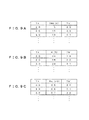
- a table shown in Fig. 7A in which the value of the reaction resistance Rr, the value of current Imes and the corrected reaction resistance R'r are associated is, for example, stored in the ROM 10b as a table 10bb, and correction can be performed based on this table.
- Fig. 7A a table shown in which the value of the reaction resistance Rr, the value of current Imes and the corrected reaction resistance R'r are associated is, for example, stored in the ROM 10b as a table 10bb, and correction can be performed based on this table.
- a reference case is determined to be a case where the current is 0, and the reaction resistance Rr for a case where the current is not 0 is corrected to the reference case of 0.
- the reaction resistance Rr is 2.5 m ⁇
- it is corrected to 2.6 m ⁇ for a case where the current Imes is 5A
- 2.7 m ⁇ for a case where the current Imes is 10A
- 2.8 m ⁇ for a case where the current Imes is 15A.
- An average current during the measurement can be used as the current value Imes.
- the process of step S14 may be performed, for example, between steps S11 and S12.
- step S15 the CPU 10a performs a temperature-based correction on the reaction resistance Rr corrected in step S14.
- the reaction resistance Rr has characteristics that decreases as the temperature increases, correction is performed in such a manner that the reaction resistance Rr becomes constant regardless of the temperature.
- a table as shown in Fig. 7B indicating an association between the value of the reaction resistance Rr, the temperature K and the corrected reaction resistance R'r is, for example, stored in the ROM 10b as a table 10bb, and correction can be performed based on this table. It is to be noted that in the example of Fig.
- a case where the temperature is 25°C is taken as a reference and the reaction resistance Rr for a case where the temperature is not 25°C is corrected to the reference case of 25°C.
- the reaction resistance Rr is 2.5 m ⁇
- it is corrected to 2.6 m ⁇ for a case of 30°C
- it remains unchanged at 2.5 m ⁇ for a case of 25°C
- it is corrected to 2.4 m ⁇ for a case of 20°C.
- the process of step S15 can be inserted between steps S11 and S12.
- a load on the process can be reduced by performing the correction collectively after completion of the learning process.
- step S16 the CPU 10a performs correction based on the degradation of the lead-acid battery 13 on the reaction resistance Rr corrected in step S15.
- correction is performed in such a manner that the reaction resistance Rr becomes constant regardless of the progress of the degradation.
- a method of correction for example, in a case where the corrected reaction resistance Rr corrected in step S15 is set as Rr again, a table shown in Fig.
- step S16 can be inserted between steps S11 and S12.
- a load of the process can be reduced by performing the correction collectively after the completion of the learning process.
- step S17 the CPU 10a compares Rr' obtained by the corrections in steps S14-S16 with the threshold value Th. In a case where Rr' ⁇ Th is satisfied (step S17:Yes), the process proceeds to step S18. Otherwise (step S17:No), the process proceeds to step S19.
- Fig. 8 is a plot illustrating a relationship between the reaction resistance Rr and the SOC. In this plot, the "x" indicates each measurement point. In this example, the value of the reaction resistance Rr increases from around a point where SOC exceeds 84%, and rapidly increases after having exceeded 88%. Accordingly, for example, 2 m ⁇ can be selected as the threshold Th. In such a case, in a case where Rr' ⁇ 2 m ⁇ is satisfied, the process proceeds to step S17.
- step S18 the CPU 10a determines that the lead-acid battery 13 is in a fully charged state. For example, by controlling a regulator (not shown) installed in the alternator 15 and decreasing a power generation voltage of the alternator 15, reduces the load of the reciprocating engine and improves fuel efficiency.
- a regulator not shown
- step S19 the CPU 10a determines that the lead-acid battery 13 is not in a fully charged state. For example, by controlling a regulator (not shown) installed in the alternator 15 and increasing a power generation voltage of the alternator 15, performs charging of the lead-acid battery 13 by the alternator 15.
- a regulator not shown
- step S30 the CPU 10a substitutes a value obtained by adding the previous value T n-1 and ⁇ T into a variable indicating time T n .
- ⁇ T may be several msec to several hundreds of msec.
- step S31 the CPU 10a measures the current In, the voltage V n and the temperature K based on the detection signals from the current detecting unit 12, the voltage detecting unit 11 and the temperature detecting unit 14.
- step S32 the CPU 10a applies the following Equation 1 to the voltage V n measured in step S31, and computes a voltage drop ⁇ V n .
- OCV stands for a stable open circuit voltage and represents an open circuit voltage at an electrochemical equilibrium state.
- the stable open circuit voltage need not be in a completely electrochemical equilibrium state, and may include a state near equilibrium.
- the OCV may be a terminal voltage of the lead-acid battery 13 measured immediately before the start up of the lead-acid battery 13 or a stable open circuit voltage of the lead-acid battery 13 estimated from a charge-discharge state of the lead-acid battery 13.
- step S32 the CPU 10a updates a Jacobian matrix F n in accordance with the following Equation 2 using an n-th observed value and a previous state vector estimation value.
- step S35 the CPU 10a derives a one-step ahead state vector X n+1
- n F n ⁇ X n + U n
- Equation 8 an observation equation and a predicted observed value Y n+1
- n can be determined as expressed in Equation 8.
- step S36 based on a one-step ahead predicted value of the state vector X n+1
- the current value and the voltage value are measured when the lead-acid battery 13 is in a charged state, and, based on the measured current value and voltage value and using an extended Kalman filter, the parameters are optimized by performing an adaptive learning on the equivalent circuit model. Then, a parameter corresponding to the reaction resistance Rr is obtained from among the optimized parameters, and, in a case where the reaction resistance Rr is greater than or equal to the threshold Th, it is determined to be in a fully charged state. Since a value of the reaction resistance Rr during charging shows a rapid change when it comes to a fully charged state, determination of whether it is in a fully charged state or not can be performed in a facilitated manner. Further, since such a rapid change does not depend on a type or an individual of the lead-acid battery 13, the fully charged state can be determined accurately regardless of the type or the individual.
- the reaction resistance value Rr since the reaction resistance value Rr has been corrected based on the current value, the temperature and the degradation, the fully charged state can be determined accurately regardless of the magnitude of the current, whether the temperature is high or low and the progress of degradation.
- the fully charged state can be determined accurately even in a noisy environment.
- the electric current always fluctuates due to operation of, for example, the load 17 such as a steering motor or a defogger, and such a fluctuation acts as a noise.
- the fully charged state can be determined accurately even under presence of such a noise.
- adaptive learning is carried out using an extended Kalman filter, but other method may be used. Specifically, adaptive learning may be carried out using a least square method, or adaptive learning may be carried out using a neural network model, a support vector machine or a genetic algorithm model.
- each parameter in Equations 9 and 10 may be updated by a sequential operation method that updates the parameters to optimum values, such as a Gauss-Newton method or a Levenberg-Marquardt method, in which M is sequentially decreased from an initial value determined in advance.
- an appropriate kernel function is defined for the case of the support vector machine and an appropriate network such as a multistage perceptron is defined for the case of the neural network. Then, using known data of a combination of correct solutions of the constants of the aforementioned equivalent circuit model for the inputs such as the current, the voltage and the temperature empirically determined in advance, a separating hyperplane is determined for the case of the support vector machine and a threshold/coupling coefficient of firing of neuron cells are determined to be optimal for the case of a neural network. Then, an optimum equivalent circuit model can be outputted for arbitrary data inputs regarding electric current, voltage and temperature.
- N individuals including all parameters are prepared and each parameter of each individual is generated randomly.
- Vcal is calculated for each individual, and by taking an absolute value of a difference between the measured V and Vcal as a fitness, natural selection is carried out in accordance with the fitness, and a next generation individual is created by performing crossing-over, mutation and copying on each individual. For example, by repeating such operations, the parameters can be optimized.
- the reaction resistance Rr is corrected using the table shown in Fig. 7 , but may also be corrected using a polynomial or the like that approximates relationships between the current, the temperature and the degradation, respectively, and the reaction resistance Rr.
- the threshold Th may be corrected in accordance with the current, the temperature and the degradation.
- Figs. 9A to 9C are diagrams illustrating the current, the temperature and the degradation, respectively, and the threshold Th before and after correction.
- Fig. 9A is a diagram illustrating the relationship between the threshold Th before correction, the measured current Imes and the threshold Th' after correction.
- the threshold Th' after correction decreases as the current value increases.
- Fig. 9B is a diagram illustrating the relationship between the threshold Th before correction, the measured temperature K and the threshold Th' after correction.
- a case where the temperature is 25°C is taken as a reference, and the threshold Th' after correction is set to a smaller value in a case where the temperature is higher than 25°C and the threshold Th' after correction is set to a larger value in a case where the temperature is lower than 25°C.
- determination of whether or not it is in a fully charged state is carried out only once, but the process shown in Fig. 5 may be carried out for a plurality of times and the final decision of whether it is in a fully charged state may be made in response to a frequency of occurrence that it is determined to be in a fully charged state. With such an embodiment, the determination of whether it is in a fully charged state can be made more accurately.
- the lead-acid battery was described by way of example, but the present invention may also be applied to other types of battery (e.g., a nickel-cadmium batter, etc).
- the equivalent circuit model 30 may be modified depending on the type of battery.
- control unit 10 may be a CPU, a ROM, a RAM, etc., but may also be a DSP (Digital Signal Processor) and the like.
- DSP Digital Signal Processor
Abstract
Description
- The present invention relates to a full charge sensing apparatus and a full charge sensing method.
- In the related art, determination of whether a secondary battery has reached a fully charged state is carried out by determining whether or not an SOC (State of Charge), which is a charging rate, has reached 100%. Such an SOC-sensing method may be, for example, a method as disclosed in
Patent Document 1 in which a stable voltage OCV (Open Circuit Voltage) of the secondary battery is measured and an SOC is predicted from this OCV. -
Patent Document 2 discloses a technique in which, since SOV=100% does not always hold at the time the OCV is measured, in order to deal with such a case, a change in SOC after the measurement of OCV is computed by hour integration based on a continuous observation of an electric current. -
- Patent Document 1: Japanese Laid-Open Patent Application No.
2005-091217 - Patent Document 2: Japanese Laid-Open Patent Application No.
2008-145349 - With the technique disclosed in
Patent Document 1, a fully charged state is determined based on a correlation between OCV and SOC, and the correlation between OCV and SOC varies depending on a type of the secondary battery. Therefore, for example, as in the case of a lead-acid battery of automobiles where a product arbitrarily selected from a group of products supplied from various manufactures by a user is used, there may be a case in which the fully charged state cannot be determined accurately. - With the technique disclosed in
Patent Document 2, in order to compute a change in SOC caused by the entering/exiting of the electric current into/out of the secondary battery, it is necessary to compute a ratio of an amount of entry/exit against a capacity of the secondary battery. However, there may be a case where the fully charged state cannot be determined accurately, since an individual difference and a sensing error exist for this capacity. - Therefore, an object of the present invention is to provide a full charge sensing apparatus and a full charge sensing method capable of accurately determining the fully charged state regardless of the type of secondary battery.
- In order to solve the aforementioned problem, a full charge sensing apparatus of an aspect of the invention is a full charge sensing apparatus for sensing a fully charged state of a secondary battery based on an equivalent circuit model of the secondary battery, the apparatus including a measuring unit that measures a voltage and a current during charging of the secondary battery, a learning unit that performs a learning process on a plurality of parameters in the equivalent circuit model using a result of measurement of the measuring unit, and a determining unit that determines that the secondary battery is in a fully charged state in a case where, among the parameters on which the learning process has been performed by the learning unit, a parameter corresponding to a reaction resistance of the secondary battery is greater than a predetermined threshold.
With such a configuration, a full charge sensing apparatus can be provided that is capable of accurately determining a fully charged state regardless of the type of the secondary battery. - According to another aspect, in addition to the above aspect, one of the learning unit and the detecting unit corrects one of a value of the reaction resistance and the threshold based on a value of the current.
With such a configuration, the fully charged state can be accurately sensed regardless of a magnitude of the electric current. - According to yet another aspect, in addition to the above aspect, one of the learning unit and the detecting unit corrects one of a value of the reaction resistance and the threshold based on a temperature of the secondary battery.
With such a configuration, the fully charged state can be accurately sensed regardless of whether the temperature is high or low. - According to still another aspect, one of the learning unit and the detecting unit corrects one of a value of the reaction resistance and the threshold based on a state of degradation of the secondary battery.
With such a configuration, the fully charged state can be accurately detected regardless of the state of degradation of the battery. - According to still another aspect, in addition to the above aspect, the learning unit optimizes the plurality of parameters by a Kalman filter operation in such a manner that errors between values of the voltage and the current measured by the measuring unit and a response of the equivalent circuit model are minimized.
With such a configuration, the fully charged state can be accurately detected even in an environment under presence of a noise. - According to still another aspect, in addition to the above aspect, the learning unit optimizes the plurality of parameters by a least square operation in such a manner that errors between values of the voltage and the current measured by the measuring unit and a response of the equivalent circuit model are minimized.
With such a configuration, a robust sensing apparatus can be provided. - According to still another aspect, in addition to the above aspect, the learning unit optimizes the plurality of parameters by a neural network in such a manner that errors between values of the voltage and the current measured by the measuring unit and a response of the equivalent circuit model are minimized.
With such a configuration, a good sensing result can be obtained by a comparatively small computation amount. - According to another aspect, in addition to the above aspect, the learning unit optimizes the plurality of parameters by a support vector machine in such a manner that errors between values of the voltage and the current measured by the measuring unit and a response of the equivalent circuit model are minimized.
With such a configuration, an appropriate parameter is derived without the learning being halted at a local optimum solution and thus the fully charged state can be accurately detected based on the parameter. - According to yet another aspect, a secondary battery power source system has the aforementioned full charge sensing system.
With such a configuration, a secondary battery power source system can be provided that is capable of accurately determining the fully charged state regardless of the type of the secondary battery. - According to a full charge sensing method of an aspect of the invention, in a full charge sensing method of sensing a fully charged state of a secondary battery based on an equivalent circuit model of the secondary battery, the method includes a measuring step of measuring a voltage and a current during charging of the secondary battery, a learning step of performing a learning process on a plurality of parameters in the equivalent circuit model using a result of measurement of the measuring step, and a determining step of performing a determination in which the secondary battery is determined to be in a fully charged state in a case where a parameter corresponding to a reaction resistance of the secondary battery is greater than a predetermined threshold, the parameter corresponding to the reaction resistance of the secondary battery being one of the parameters on which the learning process has been performed in the learning step.
With such a method, a full charge sensing method can be provided that can accurately determine the fully charged state regardless of the type of secondary battery. - According to an aspect of the invention, a full charge sensing apparatus and a full charge sensing method can be provided that can accurately determine the fully charged state regardless of the type of secondary battery.
-
- [
Fig. 1] Fig. 1 is a diagram illustrating an exemplary configuration of a full charge sensing apparatus of an embodiment of the present invention. - [
Fig. 2] Fig. 2 is a diagram illustrating an exemplary configuration of a control unit ofFig. 1 . - [
Fig. 3] Fig. 3 is a diagram for explaining a process algorithm executed in the present embodiment. - [
Fig. 4] Fig. 4 is a diagram illustrating an exemplary equivalent circuit model of a lead-acid battery. - [
Fig. 5] Fig. 5 is a flowchart for explaining a flow of a process executed according to the embodiment shown inFig. 1 . - [
Fig. 6] Fig. 6 is a flowchart for explaining details of the process of step S11 inFig. 5 . - [
Fig. 7] Figs. 7A to 7C are exemplary tables for correction of a reaction resistance. - [
Fig.8] Fig. 8 is a plot illustrating a relationship between the reaction resistance and SOC. - [
Fig. 9] Figs. 9A to 9C are exemplary tables for correction of a threshold. - Hereinafter, embodiments of the present invention will be described.
-
Fig. 1 is a diagram illustrating an exemplary configuration of a secondary battery power source system having a full charge sensing apparatus according to an embodiment of the present invention. As shown inFig. 1 , a fullcharge sensing apparatus 1 of the present embodiment includes, as its main constituent elements, a control unit 10 (corresponds to a "learning unit" and a "determining unit" in the claims), a voltage detecting unit 11 (corresponds to a "measuring unit" in the claims), a current detecting unit 12 (corresponds to a "measuring unit" in the claims) and atemperature detecting unit 14, and senses a fully charged state of a lead-acid battery 13 (corresponds to a "secondary battery" in the claims). In this example, analternator 15, astarter motor 16 and aload 17 are connected to the lead-acid battery 13 via the current detectingunit 12. In the present embodiment, the fullcharge sensing apparatus 1 will be described for a case where it is, for example, installed in a vehicle such as an automobile. However, it may also be used for other applications. - As shown in
Fig. 2 , thecontrol unit 10 includes, as its main constituent elements, a CPU (Central Processing Unit) 10a, a ROM (Read Only Memory) 10b, a RAM (Random Access Memory) 10c and an I/F (Interface) 10d. The CPU 10a controls each constituent element of the apparatus in accordance with a program 10ba stored in the ROM 10b. The ROM 10b may be a semiconductor memory and stores a program 10ba, a table 10bb and other information. The RAM 10c may be a semiconductor memory and stores a parameter 10ca and other information in a rewritable manner. The I/F 10d converts detection signals from the voltage detecting unit 11, the current detectingunit 12 and thetemperature detecting unit 14 into digital signals and inputs them, and, when the lead-acid battery 13 has come to a fully charged state, reduces a load on an engine such as a reciprocating engine (not shown) by cutting off an electromagnetic clutch (not shown) of thealternator 15. - The voltage detecting unit 11 detects a terminal voltage of the lead-
acid battery 13 and notifies thecontrol unit 10 of the terminal voltage. Thecurrent detecting unit 12 detects an electric current flowing through the lead-acid battery 13 and notifies thecontrol unit 10 of the electric current. Thetemperature detecting unit 14, which may be, for example, a thermistor, detects the temperature of the lead-acid battery 13 or an ambient temperature of the lead-acid battery 13 and notifies thecontrol unit 10 of the temperature. Thealternator 15 may be, for example, driven by an engine such as a reciprocating engine and charge the lead-acid battery 13 by generating a direct current power. Thestarter motor 16 may, for example, include a direct current motor, rotate by a direct current supplied from the lead-acid battery 13 and start up the engine. Theload 17 may, for example, include devices such as a steering motor, defogger, head lamp, a windshield wiper, a direction indicator lamp, and a navigating device. -
Fig. 3 is a diagram for explaining an outline of a process algorithm which is realized by executing a program 10ba. As shown inFig. 3 , in the present embodiment, anequivalent circuit model 30 for the lead-acid battery 13 is built which has a plurality of parameters. Then, a measured value is obtained by measuring the target lead-acid battery 13 and a calculated value corresponding to the measured value is obtained in accordance with theequivalent circuit model 30. By computing a deviation between these measured value and the calculated value, optimal parameters are estimated by adaptive learning based on anextended Kalman filter 31. Then, by updating theequivalent circuit model 30 with the estimated parameters, theequivalent circuit model 30 can be optimized. A fullcharge sensing module 32 senses a fully charged state based on the optimally learned parameter Rr. - In this specification, "adaptive learning" is a method in which a flexible and general model having parameters is prepared and the parameters are statistically and adaptively optimized by learning. In each of the embodiments described below, an extended Kalman filter is used as an example of adaptive learning. However, the present invention is not limited thereto, and, for example, a least square method-based adaptive learning, a neural network model-based adaptive learning, a support vector machine-based adaptive learning or a genetic algorithm-based adaptive learning may also be employed. In other words, any method can be employed as long as it is a method in which a model of a target to be learnt is built and parameters constituting the model are optimized with a result obtained by observation.
-
Fig. 4 is an exemplary diagram illustrating an equivalent circuit model 30 (in this example, an electric equivalent circuit) of the lead-acid battery 13. In this example, theequivalent circuit model 30 includes, as its main constituent elements, a voltage source V0, a solution resistance Rs, a reaction resistance Rr, and a capacitor C. - Here, the solution resistance Rs is an internal resistance including, as its main elements, a solution resistance of an electrolyte and a conductive resistance of an electrode of the lead-
acid battery 13. An impedance Z is an equivalent circuit corresponding to a positive electrode of the lead-acid battery 13 and the electrolyte in contact with the positive electrode. The impedance basically has a characteristic in accordance with Butler-Volmer's equation and can be expressed as a parallel-connected circuit of the reaction resistance Rr and the capacitor C. The voltage source V0 is an ideal voltage source having an internal impedance of 0. - Hereinafter, an operation of the present embodiment will be described. Hereinafter, first, the principle of operation of the present embodiment will be explained and then a detailed operation will be described with reference to
Figs. 5 and6 . - In the present embodiment, using the equivalent circuit model of the lead-
acid battery 13 shown inFig. 4 , a state vector is defined which includes at least the reaction resistance Rr of this equivalent circuit model as the parameters. In a case where the lead-acid battery 13 is in a charged state, a current value and a voltage value are obtained as the measured values, and the parameters are optimized statistically and adaptively by a learning process. Then, the reaction resistance Rr is obtained from the optimized parameters, and in a case where the reaction resistance Rr is greater than a predetermined threshold Th, the lead-acid battery 13 is determined to be in a fully charged state.Fig. 8 is a plot illustrating an exemplary relationship between the reaction resistance Rr and an SOC. In this example, the value of the reaction resistance Rr increases from around a point where the SOC exceeds 84%, and sharply increases from a point exceeding 88%. In other words, since the reaction resistance Rr during charge rapidly increases as the SOC reaches near 90%, the fully charged state can be detected by detecting that the reaction resistance Rr has become greater than the predetermined threshold Th. - In this manner, in the present embodiment, the equivalent circuit model including the reaction resistance Rr is created and the parameters constituting the equivalent circuit model are optimized by adaptive learning. Then, the reaction resistance Rr is obtained from the optimized parameters, and, in a case where the reaction resistance Rr is greater than the predetermined threshold Th, it is determined to be in a fully charged state. Here, regarding the behavior of the reaction resistance Rr during the charging, since there is not much difference due to the type or individual difference of the lead-
acid battery 13, erroneous detection due to a difference in the type of lead-acid battery 13 (e.g., the difference in the manufacturer and the difference in the production lot) or a difference due to individual difference can be prevented. -
Fig. 5 is a flowchart for explaining a flow of a process executed according to the aspect of the invention shown inFig. 1 . When the process of this flowchart is initiated, the following steps are performed. - In step S10, the CPU 10a determines whether or not it is during charging of the lead-
acid battery 13, based on a current value supplied from the current detectingunit 12 and a voltage value supplied from the voltage detecting unit 11. If it is during charging (step S10: Yes), the process proceeds to step S11. Otherwise (step S10: No), a similar process is repeated. For example, in a case where the voltage detected by the voltage detecting unit 11 is greater than or equal to the predetermined value and the current detectingunit 12 has detected that the current having a value greater than or equal to a predetermined value is flowing in a direction into the lead-acid battery 13, it is determined to be during charging and the process proceeds to step S11. - In step S11, the CPU 10a carries out a learning process on the
equivalent circuit model 30 shown inFig. 3 . Details of this learning process will be described later with reference toFig. 6 . - In step S12, the CPU 10a determines whether a value of the parameter to be learned in step S11 has converged. If it is determined to have converged (step S12:Yes), the process proceeds to step S13. Otherwise (step S12:No), the process returns to step S11 and a similar process is repeated. For example, a standard deviation of a residual of the reaction resistance Rr to be determined in step S17 may be derived, and it can be determined to have converged if the standard deviation becomes less than or equal to the predetermined threshold. In order to avoid false determination, time may be included in the elements to be determined. Specifically, it can be determined to have converged in a case where the standard deviation has come to a value less than or equal to the predetermined threshold after a predetermined time elapsed. Alternatively, it can be determined to have converged in a case where a predetermined time has elapsed after the standard deviation has come to a value less than or equal to the predetermined threshold.
- In step S13, the CPU 10a obtains a value of the reaction resistance Rr from the parameters obtained by the learning process of step S11.
- In step S14, the CPU 10a performs a current-based correction on the reaction resistance Rr obtained in step S13. In other words, since the reaction resistance Rr has characteristics that rapidly decrease as the current increases from 0, and converges to a predetermined value as the voltage value becomes large to some extent, a correction is performed such that the reaction resistance Rr becomes constant regardless of the value of the current. As a method of correction, for example, a table shown in
Fig. 7A in which the value of the reaction resistance Rr, the value of current Imes and the corrected reaction resistance R'r are associated is, for example, stored in the ROM 10b as a table 10bb, and correction can be performed based on this table. In the example ofFig. 7A , a reference case is determined to be a case where the current is 0, and the reaction resistance Rr for a case where the current is not 0 is corrected to the reference case of 0. For example, when the reaction resistance Rr is 2.5 mΩ, it is corrected to 2.6 mΩ for a case where the current Imes is 5A, 2.7 mΩ for a case where the current Imes is 10A, and 2.8 mΩ for a case where the current Imes is 15A. An average current during the measurement can be used as the current value Imes. It is to be noted that, in order to deal with a case where there is a large variation in the current value, the process of step S14 may be performed, for example, between steps S11 and S12. - In step S15, the CPU 10a performs a temperature-based correction on the reaction resistance Rr corrected in step S14. In other words, since the reaction resistance Rr has characteristics that decreases as the temperature increases, correction is performed in such a manner that the reaction resistance Rr becomes constant regardless of the temperature. As a method of correction, for example, in a case where the corrected reaction resistance after the correction in the step S14 is set as Rr again, a table as shown in
Fig. 7B indicating an association between the value of the reaction resistance Rr, the temperature K and the corrected reaction resistance R'r is, for example, stored in the ROM 10b as a table 10bb, and correction can be performed based on this table. It is to be noted that in the example ofFig. 7B , a case where the temperature is 25°C is taken as a reference and the reaction resistance Rr for a case where the temperature is not 25°C is corrected to the reference case of 25°C. For example, in a case where the reaction resistance Rr is 2.5 mΩ, it is corrected to 2.6 mΩ for a case of 30°C, it remains unchanged at 2.5 mΩ for a case of 25°C, and it is corrected to 2.4 mΩ for a case of 20°C. Similarly to the process of step S14, the process of step S15 can be inserted between steps S11 and S12. However, since variation in the temperature is not as large as that of the current, a load on the process can be reduced by performing the correction collectively after completion of the learning process. - In step S16, the CPU 10a performs correction based on the degradation of the lead-
acid battery 13 on the reaction resistance Rr corrected in step S15. In other words, since the reaction resistance Rr has characteristics that increases as the degradation of the lead-acid battery 13 progresses, correction is performed in such a manner that the reaction resistance Rr becomes constant regardless of the progress of the degradation. As a method of correction, for example, in a case where the corrected reaction resistance Rr corrected in step S15 is set as Rr again, a table shown inFig. 7C indicating an association between the value of the reaction resistance Rr, the solution resistance Rs correlated with the progression of degradation and the corrected reaction resistance R'r is, for example, stored in the ROM 10b as a table 10bb, and correction can be performed based on this table. It is to be noted that in the example ofFig. 7C , a new product condition (in this example, a state of Rs=0.5 mΩ) is taken as a reference and the reaction resistance Rr for a case where the degradation has progressed and Rs≠0.5 mΩ is corrected to the reference case of Rs=0.5 mΩ. For example, in a case where the reaction resistance Rr is 2.5 mΩ, correction is not performed when the solution resistance Rs=0.5 mΩ, and it is corrected to 2.5 mΩ for a case where the reaction resistance Rr is 2.6 mΩ and when Rs=0.6 mΩ, and it is corrected to 2.5 mΩ for a case where the reaction resistance Rr is 2.7 mΩ and when Rs=0.7 mΩ. Similarly to the process of step S14, the process of step S16 can be inserted between steps S11 and S12. However, since the variation in the gradation is not as large as that of the current, a load of the process can be reduced by performing the correction collectively after the completion of the learning process. - In step S17, the CPU 10a compares Rr' obtained by the corrections in steps S14-S16 with the threshold value Th. In a case where Rr'≥Th is satisfied (step S17:Yes), the process proceeds to step S18. Otherwise (step S17:No), the process proceeds to step S19.
Fig. 8 is a plot illustrating a relationship between the reaction resistance Rr and the SOC. In this plot, the "x" indicates each measurement point. In this example, the value of the reaction resistance Rr increases from around a point where SOC exceeds 84%, and rapidly increases after having exceeded 88%. Accordingly, for example, 2 mΩ can be selected as the threshold Th. In such a case, in a case where Rr'≥2 mΩ is satisfied, the process proceeds to step S17. - In step S18, the CPU 10a determines that the lead-
acid battery 13 is in a fully charged state. For example, by controlling a regulator (not shown) installed in thealternator 15 and decreasing a power generation voltage of thealternator 15, reduces the load of the reciprocating engine and improves fuel efficiency. - In step S19, the CPU 10a determines that the lead-
acid battery 13 is not in a fully charged state. For example, by controlling a regulator (not shown) installed in thealternator 15 and increasing a power generation voltage of thealternator 15, performs charging of the lead-acid battery 13 by thealternator 15. - Next, referring to
Fig. 6 , the details of the process in step S11 inFig. 5 will be described. When the process ofFig. 6 is initiated, the following steps are carried out. - In step S30, the CPU 10a substitutes a value obtained by adding the previous value Tn-1 and ΔT into a variable indicating time Tn. It is to be noted that, for example, ΔT may be several msec to several hundreds of msec.
- In step S31, the CPU 10a measures the current In, the voltage Vn and the temperature K based on the detection signals from the current detecting
unit 12, the voltage detecting unit 11 and thetemperature detecting unit 14. - In step S32, the CPU 10a applies the following
Equation 1 to the voltage Vn measured in step S31, and computes a voltage drop ΔVn. - [Equation 1]

- Here, OCV stands for a stable open circuit voltage and represents an open circuit voltage at an electrochemical equilibrium state. The stable open circuit voltage need not be in a completely electrochemical equilibrium state, and may include a state near equilibrium. As a method of deriving the OCV, for example, the OCV may be a terminal voltage of the lead-
acid battery 13 measured immediately before the start up of the lead-acid battery 13 or a stable open circuit voltage of the lead-acid battery 13 estimated from a charge-discharge state of the lead-acid battery 13. - In step S32, the CPU 10a updates a Jacobian matrix Fn in accordance with the following
Equation 2 using an n-th observed value and a previous state vector estimation value. - [Equation 2]

In the equation, diag() represents a diagonal matrix. - In step S34, as represented by the following
Equation 3, the CPU 10a takes ΔVn obtained by the calculation in step S32 as an actual observed value Yn of the extended Kalman filter.
[equation 3]
- In step S35, the CPU 10a derives a one-step ahead state vector Xn+1|n using the following Equation 4:
[equation 4]
- Here, Xn and Un are expressed by the following
Equations
[equation 5]
[equation 6]
- Further, by defining Hn T as expressed in the following Equation 7, an observation equation and a predicted observed value Yn+1|n can be determined as expressed in Equation 8.
- [equation 7]

- [equation 8]

- In step S36, based on a one-step ahead predicted value of the state vector Xn+1|n, an actual observed value Yn+1 and a predicted observed value Yn+1|n, the CPU 10a sequentially estimates an optimal state vector Xn using an extended Kalman filter operation by Kalman gain calculation and filtering calculation, and updates an adjustment parameter (of the equivalent circuit model) to an optimum based on the estimated state vector Xn. Then, the process returns to process of step S12 in
Fig. 5 . - As has been described above, according to the present embodiment, the current value and the voltage value are measured when the lead-
acid battery 13 is in a charged state, and, based on the measured current value and voltage value and using an extended Kalman filter, the parameters are optimized by performing an adaptive learning on the equivalent circuit model. Then, a parameter corresponding to the reaction resistance Rr is obtained from among the optimized parameters, and, in a case where the reaction resistance Rr is greater than or equal to the threshold Th, it is determined to be in a fully charged state. Since a value of the reaction resistance Rr during charging shows a rapid change when it comes to a fully charged state, determination of whether it is in a fully charged state or not can be performed in a facilitated manner. Further, since such a rapid change does not depend on a type or an individual of the lead-acid battery 13, the fully charged state can be determined accurately regardless of the type or the individual. - Further, in the present invention, since the reaction resistance value Rr has been corrected based on the current value, the temperature and the degradation, the fully charged state can be determined accurately regardless of the magnitude of the current, whether the temperature is high or low and the progress of degradation.
- Also, in the present embodiment, since adaptive learning is performed using an extended Kalman filter, the fully charged state can be determined accurately even in a noisy environment. In other words, in a case of the lead-
acid battery 13 installed in a vehicle, the electric current always fluctuates due to operation of, for example, theload 17 such as a steering motor or a defogger, and such a fluctuation acts as a noise. However, by using an extended Kalman filter, the fully charged state can be determined accurately even under presence of such a noise. - It is to be noted that the aforementioned embodiment has been described by way of example and various other variant embodiments exist. For example, in each of the aforementioned embodiment, adaptive learning is carried out using an extended Kalman filter, but other method may be used. Specifically, adaptive learning may be carried out using a least square method, or adaptive learning may be carried out using a neural network model, a support vector machine or a genetic algorithm model.
- For example, in the case of a least square method, the calculated value Vcal of the terminal voltage across both ends of the equivalent circuit model of
Fig. 4 can be expressed by the following Equation 9.
[equation 9]
- Here, I2 can be expressed by the following
Equation 10.
[equation 10]
- Then, the parameters can be optimized by performing adaptive learning on each parameter in such a manner that a sum of squares of deviation M in the following Equation 11 is minimized. As a specific example, each parameter in
Equations 9 and 10 may be updated by a sequential operation method that updates the parameters to optimum values, such as a Gauss-Newton method or a Levenberg-Marquardt method, in which M is sequentially decreased from an initial value determined in advance.
[equation 11]
It is to be noted that Vmes is an actual measured value of the voltage obtained from the voltage detecting unit 11. - Regarding the support vector machine or the neural network, an appropriate kernel function is defined for the case of the support vector machine and an appropriate network such as a multistage perceptron is defined for the case of the neural network. Then, using known data of a combination of correct solutions of the constants of the aforementioned equivalent circuit model for the inputs such as the current, the voltage and the temperature empirically determined in advance, a separating hyperplane is determined for the case of the support vector machine and a threshold/coupling coefficient of firing of neuron cells are determined to be optimal for the case of a neural network. Then, an optimum equivalent circuit model can be outputted for arbitrary data inputs regarding electric current, voltage and temperature.
- Further, in the case of a genetic algorithm, for example, N individuals including all parameters are prepared and each parameter of each individual is generated randomly. Then, Vcal is calculated for each individual, and by taking an absolute value of a difference between the measured V and Vcal as a fitness, natural selection is carried out in accordance with the fitness, and a next generation individual is created by performing crossing-over, mutation and copying on each individual. For example, by repeating such operations, the parameters can be optimized.
- Also, in the aforementioned embodiment, the reaction resistance Rr is corrected using the table shown in
Fig. 7 , but may also be corrected using a polynomial or the like that approximates relationships between the current, the temperature and the degradation, respectively, and the reaction resistance Rr. - Further, instead of correcting the reaction resistance Rr, the threshold Th may be corrected in accordance with the current, the temperature and the degradation.
Figs. 9A to 9C are diagrams illustrating the current, the temperature and the degradation, respectively, and the threshold Th before and after correction. In other words,Fig. 9A is a diagram illustrating the relationship between the threshold Th before correction, the measured current Imes and the threshold Th' after correction. In this example, the threshold Th' after correction decreases as the current value increases.Fig. 9B is a diagram illustrating the relationship between the threshold Th before correction, the measured temperature K and the threshold Th' after correction. In this example, a case where the temperature is 25°C is taken as a reference, and the threshold Th' after correction is set to a smaller value in a case where the temperature is higher than 25°C and the threshold Th' after correction is set to a larger value in a case where the temperature is lower than 25°C. Further,Fig. 9C is a diagram illustrating the relationship between the threshold Th before correction, the solution resistance Rs indicating the degradation, and the threshold Th' after correction. In this example, a case where Rs=0.5mΩ corresponding to a new product condition is taken as a reference, and the threshold Th' after correction is set to a larger value as Rs becomes larger with the progress of the degradation. - Further, as shown in
Fig. 5 , in the aforementioned embodiment, determination of whether or not it is in a fully charged state is carried out only once, but the process shown inFig. 5 may be carried out for a plurality of times and the final decision of whether it is in a fully charged state may be made in response to a frequency of occurrence that it is determined to be in a fully charged state. With such an embodiment, the determination of whether it is in a fully charged state can be made more accurately. - Further, in the aforementioned embodiment, the lead-acid battery was described by way of example, but the present invention may also be applied to other types of battery (e.g., a nickel-cadmium batter, etc). In such a case, the
equivalent circuit model 30 may be modified depending on the type of battery. - Further, in the aforementioned embodiments, the
control unit 10 may be a CPU, a ROM, a RAM, etc., but may also be a DSP (Digital Signal Processor) and the like. -
- 1
- full charge sensing apparatus,
- 10
- control unit (learning unit, determining unit),
- 10a
- CPU
- 10b
- ROM,
- 10c
- RAM,
- 10d
- I/F,
- 11
- voltage detecting unit (measuring unit),
- 12
- current detecting unit (measuring unit),
- 13
- lead-acid battery (secondary battery),
- 14
- temperature detecting unit,
- 15
- alternator,
- 16
- starter motor,
- 17
- load,
- 30
- equivalent circuit model,
- 31
- extended Kalman filter,
- Rr
- reaction resistance,
- Rs
- solution resistance
Claims (10)
- A full charge sensing apparatus for sensing a fully charged state of a secondary battery based on an equivalent circuit model of the secondary battery, the apparatus comprising:a measuring unit that measures a voltage and a current during charging of the secondary battery;a learning unit that performs a learning process on a plurality of parameters in the equivalent circuit model using a result of measurement of the measuring unit; anda determining unit that determines that the secondary battery is in a fully charged state in a case where, among the parameters on which the learning process has been performed by the learning unit, a parameter corresponding to a reaction resistance of the secondary battery is greater than a predetermined threshold.
- The full charge sensing apparatus according to claim 1, wherein one of the learning unit and the detecting unit corrects one of a value of the reaction resistance and the threshold based on a value of the current.
- The full charge sensing apparatus according to claim 1 or 2, wherein one of the learning unit and the detecting unit corrects one of a value of the reaction resistance and the threshold based on a temperature of the secondary battery.
- The full charge sensing apparatus according to any one of claims 1 to 3, wherein one of the learning unit and the detecting unit corrects one of a value of the reaction resistance and the threshold based on a state of degradation of the secondary battery.
- The full charge sensing apparatus according to any one of claims 1 to 4, wherein the learning unit optimizes the plurality of parameters by a Kalman filter operation in such a manner that errors between values of the voltage and the current measured by the measuring unit and a response of the equivalent circuit model are minimized.
- The full charge sensing apparatus according to any one of claims 1 to 4, wherein the learning unit optimizes the plurality of parameters by a least square operation in such a manner that errors between values of the voltage and the current measured by the measuring unit and a response of the equivalent circuit model are minimized.
- The full charge sensing apparatus according to any one of claims 1 to 4, wherein the learning unit optimizes the plurality of parameters by a neural network in such a manner that errors between values of the voltage and the current measured by the measuring unit and a response of the equivalent circuit model are minimized.
- The full charge sensing apparatus according to any one of claims 1 to 4, wherein the learning unit optimizes the plurality of parameters by a support vector machine in such a manner that errors between values of the voltage and the current measured by the measuring unit and a response of the equivalent circuit model are minimized.
- A secondary battery power source system having the full charge sensing apparatus according to any one of claims 1 to 8.
- A full charge sensing method of sensing a fully charged state of a secondary battery based on an equivalent circuit model of the secondary battery, the method comprising:a measuring step of measuring a voltage and a current during charging of the secondary battery;a learning step of performing a learning process on a plurality of parameters in the equivalent circuit model using a result of measurement of the measuring step; anda determining step of performing a determination in which the secondary battery is determined to be in a fully charged state in a case where a parameter corresponding to a reaction resistance of the secondary battery is greater than a predetermined threshold, the parameter corresponding to the reaction resistance of the secondary battery being one of the parameters on which the learning process has been performed in the learning step.
Applications Claiming Priority (2)
| Application Number | Priority Date | Filing Date | Title |
|---|---|---|---|
| JP2010283564A JP5307113B2 (en) | 2010-12-20 | 2010-12-20 | Full charge detection device and full charge detection method |
| PCT/JP2011/079459 WO2012086627A1 (en) | 2010-12-20 | 2011-12-20 | Full-charge detection device, and full-charge detection method |
Publications (3)
| Publication Number | Publication Date |
|---|---|
| EP2657714A1 true EP2657714A1 (en) | 2013-10-30 |
| EP2657714A4 EP2657714A4 (en) | 2017-10-04 |
| EP2657714B1 EP2657714B1 (en) | 2021-04-14 |
Family
ID=46313896
Family Applications (1)
| Application Number | Title | Priority Date | Filing Date |
|---|---|---|---|
| EP11851717.6A Active EP2657714B1 (en) | 2010-12-20 | 2011-12-20 | Full-charge detection device, and full-charge detection method |
Country Status (5)
| Country | Link |
|---|---|
| US (1) | US9153988B2 (en) |
| EP (1) | EP2657714B1 (en) |
| JP (1) | JP5307113B2 (en) |
| CN (1) | CN103229068B (en) |
| WO (1) | WO2012086627A1 (en) |
Cited By (1)
| Publication number | Priority date | Publication date | Assignee | Title |
|---|---|---|---|---|
| CN110138035A (en) * | 2019-05-22 | 2019-08-16 | 深圳市海派通讯科技有限公司 | Mobile terminal charging control method |
Families Citing this family (25)
| Publication number | Priority date | Publication date | Assignee | Title |
|---|---|---|---|---|
| JP5944291B2 (en) * | 2012-10-05 | 2016-07-05 | カルソニックカンセイ株式会社 | Battery parameter estimation apparatus and method |
| KR101547006B1 (en) * | 2012-10-26 | 2015-08-24 | 주식회사 엘지화학 | Apparatus and method for estimating state of charging of battery |
| CN105027378B (en) * | 2012-11-08 | 2017-05-24 | 新电元工业株式会社 | Secondary cell system having plurality of cells, and method for distributing charge/discharge electric power |
| JP5925888B2 (en) * | 2012-11-08 | 2016-05-25 | 新電元工業株式会社 | Motorcycle engine control circuit and motorcycle engine control method |
| JP5810116B2 (en) | 2013-03-14 | 2015-11-11 | 古河電気工業株式会社 | Secondary battery state detection device and secondary battery state detection method |
| US10393813B2 (en) * | 2013-08-27 | 2019-08-27 | The Regents Of The University Of Michigan | On-board state of health monitoring of batteries using incremental capacity analysis |
| JP6044512B2 (en) * | 2013-11-07 | 2016-12-14 | 株式会社デンソー | Battery characteristics learning device |
| WO2015151848A1 (en) * | 2014-04-01 | 2015-10-08 | 古河電気工業株式会社 | Secondary battery state detection device and secondary battery state detection method |
| JP6277864B2 (en) * | 2014-05-26 | 2018-02-14 | 株式会社デンソー | Battery internal state estimation device |
| WO2016031191A1 (en) * | 2014-08-28 | 2016-03-03 | 日本電気株式会社 | Information processing device, information processing method and storage medium |
| JP2016090330A (en) * | 2014-10-31 | 2016-05-23 | カルソニックカンセイ株式会社 | Battery parameter estimation device |
| FR3029315B1 (en) * | 2014-11-28 | 2016-12-09 | Renault Sa | AUTOMATIC METHOD OF ESTIMATING THE CAPACITY OF A CELL OF A BATTERY |
| JP6390471B2 (en) * | 2015-03-09 | 2018-09-19 | 株式会社デンソー | Secondary battery control device |
| JP6354700B2 (en) * | 2015-08-07 | 2018-07-11 | 株式会社デンソー | Battery charge state estimation device |
| EP3518376B1 (en) | 2016-09-23 | 2021-08-25 | Furukawa Electric Co., Ltd. | Secondary battery state detection device and secondary battery state detection method |
| KR20180056238A (en) * | 2016-11-18 | 2018-05-28 | 삼성전자주식회사 | Battery charging method, battery charging information generating method and battery charging apparatus |
| KR102179677B1 (en) * | 2017-04-12 | 2020-11-17 | 주식회사 엘지화학 | Apparatus and method for calculating soc |
| KR102405005B1 (en) | 2017-04-14 | 2022-06-07 | 삼성전자주식회사 | Electronic apparatus for changing state of charging battery according to state of battery |
| JP6927000B2 (en) * | 2017-12-06 | 2021-08-25 | トヨタ自動車株式会社 | Deterioration state estimation method for secondary batteries |
| TWI705013B (en) * | 2017-12-29 | 2020-09-21 | 英屬開曼群島商睿能創意公司 | Exchangeable energy storage device station and method for managing exchangeable energy storage device station |
| CN109633450B (en) * | 2018-11-23 | 2021-05-14 | 成都大超科技有限公司 | Lithium battery charging detection system based on neural network |
| US11069926B1 (en) * | 2019-02-14 | 2021-07-20 | Vcritonc Alpha, Inc. | Controlling ongoing battery system usage via parametric linear approximation |
| JP7124812B2 (en) * | 2019-09-30 | 2022-08-24 | 株式会社デンソー | Battery state estimation device |
| US11498446B2 (en) * | 2020-01-06 | 2022-11-15 | Ford Global Technologies, Llc | Plug-in charge current management for battery model-based online learning |
| CN113541649B (en) * | 2021-06-21 | 2024-03-29 | 苏州大学 | Variable step length kernel number error self-adaptive filter |
Family Cites Families (20)
| Publication number | Priority date | Publication date | Assignee | Title |
|---|---|---|---|---|
| US6081097A (en) * | 1998-01-19 | 2000-06-27 | Matsushita Electric Industrial Co., Ltd. | Method for charging lithium secondary battery |
| JP4759795B2 (en) * | 2000-09-28 | 2011-08-31 | 株式会社Gsユアサ | Rechargeable battery remaining capacity detection method |
| US7072871B1 (en) * | 2001-08-22 | 2006-07-04 | Cadex Electronics Inc. | Fuzzy logic method and apparatus for battery state of health determination |
| CN101639523B (en) * | 2003-06-27 | 2011-07-27 | 古河电气工业株式会社 | Method and device for measuring internal impedance of secondary battery, method and device for determining deterioration, and power supply system |
| JP4015092B2 (en) | 2003-09-18 | 2007-11-28 | 古河電気工業株式会社 | Secondary battery deterioration state determination method, secondary battery deterioration state determination device, and power supply system |
| WO2005015252A1 (en) | 2003-06-27 | 2005-02-17 | The Furukawa Electric Co., Ltd. | Method for judging deterioration of accumulator, method for measuring secondary cell internal impedance, device for measuring secondary cell internal impedance, device for judging deterioration of secondary cell, and power source system |
| US7227335B2 (en) * | 2003-07-22 | 2007-06-05 | Makita Corporation | Method and apparatus for diagnosing the condition of a rechargeable battery |
| JP4074596B2 (en) * | 2004-03-18 | 2008-04-09 | 日立マクセル株式会社 | Rechargeable battery or rechargeable battery pack |
| US8344685B2 (en) * | 2004-08-20 | 2013-01-01 | Midtronics, Inc. | System for automatically gathering battery information |
| JP4952971B2 (en) * | 2005-07-12 | 2012-06-13 | 日立工機株式会社 | Battery life discriminator |
| DE102006036784A1 (en) * | 2006-08-07 | 2008-02-14 | Robert Bosch Gmbh | Method for determining the battery capacity based on capacity-dependent parameters |
| JP4940889B2 (en) * | 2006-10-24 | 2012-05-30 | 株式会社豊田中央研究所 | Battery characteristic detection method and battery characteristic detection apparatus |
| JP4865523B2 (en) | 2006-12-12 | 2012-02-01 | 古河電気工業株式会社 | Battery charge rate estimation method, battery charge rate estimation device, and battery power supply system |
| US7899631B2 (en) | 2007-03-29 | 2011-03-01 | The Furukawa Electric Co., Ltd. | Method and device for estimating battery residual capacity, and battery power supply system |
| JP4865627B2 (en) * | 2007-03-29 | 2012-02-01 | 古河電気工業株式会社 | Battery remaining capacity estimation method, battery remaining capacity estimation apparatus, and battery power supply system |
| US7928735B2 (en) * | 2007-07-23 | 2011-04-19 | Yung-Sheng Huang | Battery performance monitor |
| GB2463297A (en) * | 2008-09-09 | 2010-03-10 | Ricardo Uk Ltd | Determining a power source state of charge using an equivalent circuit model |
| US8866443B2 (en) * | 2010-08-11 | 2014-10-21 | Shin-Kobe Electric Machinery Co., Ltd. | Lead acid storage battery and lead acid storage battery system for natural energy utilization system |
| US8860420B2 (en) * | 2011-09-16 | 2014-10-14 | Blackberry Limited | Diagnostic use of physical and electrical battery parameters and storing relative condition data |
| US8719195B2 (en) * | 2011-10-10 | 2014-05-06 | The Boeing Company | Battery adaptive learning management system |
-
2010
- 2010-12-20 JP JP2010283564A patent/JP5307113B2/en active Active
-
2011
- 2011-12-20 CN CN201180057759.8A patent/CN103229068B/en active Active
- 2011-12-20 WO PCT/JP2011/079459 patent/WO2012086627A1/en active Application Filing
- 2011-12-20 EP EP11851717.6A patent/EP2657714B1/en active Active
-
2013
- 2013-02-18 US US13/769,636 patent/US9153988B2/en active Active
Non-Patent Citations (1)
| Title |
|---|
| See references of WO2012086627A1 * |
Cited By (1)
| Publication number | Priority date | Publication date | Assignee | Title |
|---|---|---|---|---|
| CN110138035A (en) * | 2019-05-22 | 2019-08-16 | 深圳市海派通讯科技有限公司 | Mobile terminal charging control method |
Also Published As
| Publication number | Publication date |
|---|---|
| EP2657714B1 (en) | 2021-04-14 |
| WO2012086627A1 (en) | 2012-06-28 |
| JP2012132724A (en) | 2012-07-12 |
| CN103229068B (en) | 2015-06-24 |
| JP5307113B2 (en) | 2013-10-02 |
| CN103229068A (en) | 2013-07-31 |
| US9153988B2 (en) | 2015-10-06 |
| US20130154577A1 (en) | 2013-06-20 |
| EP2657714A4 (en) | 2017-10-04 |
Similar Documents
| Publication | Publication Date | Title |
|---|---|---|
| EP2657714B1 (en) | Full-charge detection device, and full-charge detection method | |
| US11163010B2 (en) | Secondary battery deterioration estimation device and secondary battery deterioration estimation method | |
| US10656210B2 (en) | Secondary battery state detection device and secondary battery state detection method | |
| US10466302B2 (en) | Secondary battery state detecting device and secondary battery state detecting method | |
| US9678164B2 (en) | Battery internal state estimating apparatus and battery internal state estimating method | |
| CN104698385B (en) | Battery state calculating device and battery state calculating method | |
| TWI384246B (en) | Apparatus and method for estimating resistance characteristics of battery based on open circuit voltage estimated by battery voltage variation | |
| JP5442583B2 (en) | State detection device for power supply and power supply device | |
| RU2524050C1 (en) | Assessment device of accumulator state, and assessment method of accumulator state | |
| US11143710B2 (en) | Device for estimating degradation of secondary cell, and method for estimating degradation of secondary cell | |
| JP7028781B2 (en) | Secondary battery status detection device and secondary battery status detection method | |
| WO2006135192A1 (en) | Method and apparatus of controlling for charging/discharging voltage of battery | |
| US10393814B2 (en) | Secondary battery state detection device and secondary battery state detection method | |
| CN111527644B (en) | Rechargeable battery abnormality detection device and rechargeable battery abnormality detection method | |
| CN112105940A (en) | Parameter estimation device, parameter estimation method, and computer program | |
| JP6895786B2 (en) | Secondary battery status detection device and secondary battery status detection method | |
| US20220099745A1 (en) | Method and Apparatus for Device-Specific Determination of an Internal-Resistance Based State of Health of a Battery | |
| WO2019181138A1 (en) | Device for measuring degree of deterioration of secondary battery | |
| WO2018025306A1 (en) | Estimation device, estimation program, and charging control device | |
| JP2019113414A (en) | Secondary battery degradation degree measuring device | |
| JP2018100851A (en) | Secondary battery state detection device and secondary battery state detection method |
Legal Events
| Date | Code | Title | Description |
|---|---|---|---|
| PUAI | Public reference made under article 153(3) epc to a published international application that has entered the european phase |
Free format text: ORIGINAL CODE: 0009012 |
|
| 17P | Request for examination filed |
Effective date: 20130219 |
|
| AK | Designated contracting states |
Kind code of ref document: A1 Designated state(s): AL AT BE BG CH CY CZ DE DK EE ES FI FR GB GR HR HU IE IS IT LI LT LU LV MC MK MT NL NO PL PT RO RS SE SI SK SM TR |
|
| DAX | Request for extension of the european patent (deleted) | ||
| RA4 | Supplementary search report drawn up and despatched (corrected) |
Effective date: 20170901 |
|
| RIC1 | Information provided on ipc code assigned before grant |
Ipc: H01M 10/48 20060101ALI20170828BHEP Ipc: H02J 7/10 20060101ALI20170828BHEP Ipc: H02J 7/00 20060101ALI20170828BHEP Ipc: G01R 31/36 20060101AFI20170828BHEP Ipc: H01M 10/44 20060101ALI20170828BHEP |
|
| GRAP | Despatch of communication of intention to grant a patent |
Free format text: ORIGINAL CODE: EPIDOSNIGR1 |
|
| STAA | Information on the status of an ep patent application or granted ep patent |
Free format text: STATUS: GRANT OF PATENT IS INTENDED |
|
| RIC1 | Information provided on ipc code assigned before grant |
Ipc: H02J 7/10 20060101ALI20201009BHEP Ipc: H01M 10/44 20060101ALI20201009BHEP Ipc: H01M 10/48 20060101ALI20201009BHEP Ipc: G01R 31/367 20190101ALI20201009BHEP Ipc: G01R 31/36 20200101AFI20201009BHEP Ipc: G01R 31/3842 20190101ALI20201009BHEP Ipc: H01M 10/42 20060101ALI20201009BHEP Ipc: H02J 7/00 20060101ALI20201009BHEP Ipc: H02J 7/04 20060101ALI20201009BHEP |
|
| INTG | Intention to grant announced |
Effective date: 20201028 |
|
| GRAS | Grant fee paid |
Free format text: ORIGINAL CODE: EPIDOSNIGR3 |
|
| GRAA | (expected) grant |
Free format text: ORIGINAL CODE: 0009210 |
|
| STAA | Information on the status of an ep patent application or granted ep patent |
Free format text: STATUS: THE PATENT HAS BEEN GRANTED |
|
| AK | Designated contracting states |
Kind code of ref document: B1 Designated state(s): AL AT BE BG CH CY CZ DE DK EE ES FI FR GB GR HR HU IE IS IT LI LT LU LV MC MK MT NL NO PL PT RO RS SE SI SK SM TR |
|
| REG | Reference to a national code |
Ref country code: GB Ref legal event code: FG4D |
|
| REG | Reference to a national code |
Ref country code: CH Ref legal event code: EP |
|
| REG | Reference to a national code |
Ref country code: DE Ref legal event code: R096 Ref document number: 602011070715 Country of ref document: DE |
|
| REG | Reference to a national code |
Ref country code: IE Ref legal event code: FG4D |
|
| REG | Reference to a national code |
Ref country code: AT Ref legal event code: REF Ref document number: 1382897 Country of ref document: AT Kind code of ref document: T Effective date: 20210515 |
|
| REG | Reference to a national code |
Ref country code: LT Ref legal event code: MG9D |
|
| REG | Reference to a national code |
Ref country code: AT Ref legal event code: MK05 Ref document number: 1382897 Country of ref document: AT Kind code of ref document: T Effective date: 20210414 |
|
| REG | Reference to a national code |
Ref country code: NL Ref legal event code: MP Effective date: 20210414 |
|
| PG25 | Lapsed in a contracting state [announced via postgrant information from national office to epo] |
Ref country code: AT Free format text: LAPSE BECAUSE OF FAILURE TO SUBMIT A TRANSLATION OF THE DESCRIPTION OR TO PAY THE FEE WITHIN THE PRESCRIBED TIME-LIMIT Effective date: 20210414 Ref country code: BG Free format text: LAPSE BECAUSE OF FAILURE TO SUBMIT A TRANSLATION OF THE DESCRIPTION OR TO PAY THE FEE WITHIN THE PRESCRIBED TIME-LIMIT Effective date: 20210714 Ref country code: HR Free format text: LAPSE BECAUSE OF FAILURE TO SUBMIT A TRANSLATION OF THE DESCRIPTION OR TO PAY THE FEE WITHIN THE PRESCRIBED TIME-LIMIT Effective date: 20210414 Ref country code: NL Free format text: LAPSE BECAUSE OF FAILURE TO SUBMIT A TRANSLATION OF THE DESCRIPTION OR TO PAY THE FEE WITHIN THE PRESCRIBED TIME-LIMIT Effective date: 20210414 Ref country code: LT Free format text: LAPSE BECAUSE OF FAILURE TO SUBMIT A TRANSLATION OF THE DESCRIPTION OR TO PAY THE FEE WITHIN THE PRESCRIBED TIME-LIMIT Effective date: 20210414 Ref country code: FI Free format text: LAPSE BECAUSE OF FAILURE TO SUBMIT A TRANSLATION OF THE DESCRIPTION OR TO PAY THE FEE WITHIN THE PRESCRIBED TIME-LIMIT Effective date: 20210414 |
|
| PG25 | Lapsed in a contracting state [announced via postgrant information from national office to epo] |
Ref country code: SE Free format text: LAPSE BECAUSE OF FAILURE TO SUBMIT A TRANSLATION OF THE DESCRIPTION OR TO PAY THE FEE WITHIN THE PRESCRIBED TIME-LIMIT Effective date: 20210414 Ref country code: RS Free format text: LAPSE BECAUSE OF FAILURE TO SUBMIT A TRANSLATION OF THE DESCRIPTION OR TO PAY THE FEE WITHIN THE PRESCRIBED TIME-LIMIT Effective date: 20210414 Ref country code: LV Free format text: LAPSE BECAUSE OF FAILURE TO SUBMIT A TRANSLATION OF THE DESCRIPTION OR TO PAY THE FEE WITHIN THE PRESCRIBED TIME-LIMIT Effective date: 20210414 Ref country code: GR Free format text: LAPSE BECAUSE OF FAILURE TO SUBMIT A TRANSLATION OF THE DESCRIPTION OR TO PAY THE FEE WITHIN THE PRESCRIBED TIME-LIMIT Effective date: 20210715 Ref country code: IS Free format text: LAPSE BECAUSE OF FAILURE TO SUBMIT A TRANSLATION OF THE DESCRIPTION OR TO PAY THE FEE WITHIN THE PRESCRIBED TIME-LIMIT Effective date: 20210814 Ref country code: NO Free format text: LAPSE BECAUSE OF FAILURE TO SUBMIT A TRANSLATION OF THE DESCRIPTION OR TO PAY THE FEE WITHIN THE PRESCRIBED TIME-LIMIT Effective date: 20210714 Ref country code: PT Free format text: LAPSE BECAUSE OF FAILURE TO SUBMIT A TRANSLATION OF THE DESCRIPTION OR TO PAY THE FEE WITHIN THE PRESCRIBED TIME-LIMIT Effective date: 20210816 Ref country code: PL Free format text: LAPSE BECAUSE OF FAILURE TO SUBMIT A TRANSLATION OF THE DESCRIPTION OR TO PAY THE FEE WITHIN THE PRESCRIBED TIME-LIMIT Effective date: 20210414 Ref country code: ES Free format text: LAPSE BECAUSE OF FAILURE TO SUBMIT A TRANSLATION OF THE DESCRIPTION OR TO PAY THE FEE WITHIN THE PRESCRIBED TIME-LIMIT Effective date: 20210414 |
|
| REG | Reference to a national code |
Ref country code: DE Ref legal event code: R097 Ref document number: 602011070715 Country of ref document: DE |
|
| PG25 | Lapsed in a contracting state [announced via postgrant information from national office to epo] |
Ref country code: CZ Free format text: LAPSE BECAUSE OF FAILURE TO SUBMIT A TRANSLATION OF THE DESCRIPTION OR TO PAY THE FEE WITHIN THE PRESCRIBED TIME-LIMIT Effective date: 20210414 Ref country code: DK Free format text: LAPSE BECAUSE OF FAILURE TO SUBMIT A TRANSLATION OF THE DESCRIPTION OR TO PAY THE FEE WITHIN THE PRESCRIBED TIME-LIMIT Effective date: 20210414 Ref country code: EE Free format text: LAPSE BECAUSE OF FAILURE TO SUBMIT A TRANSLATION OF THE DESCRIPTION OR TO PAY THE FEE WITHIN THE PRESCRIBED TIME-LIMIT Effective date: 20210414 Ref country code: SK Free format text: LAPSE BECAUSE OF FAILURE TO SUBMIT A TRANSLATION OF THE DESCRIPTION OR TO PAY THE FEE WITHIN THE PRESCRIBED TIME-LIMIT Effective date: 20210414 Ref country code: SM Free format text: LAPSE BECAUSE OF FAILURE TO SUBMIT A TRANSLATION OF THE DESCRIPTION OR TO PAY THE FEE WITHIN THE PRESCRIBED TIME-LIMIT Effective date: 20210414 Ref country code: RO Free format text: LAPSE BECAUSE OF FAILURE TO SUBMIT A TRANSLATION OF THE DESCRIPTION OR TO PAY THE FEE WITHIN THE PRESCRIBED TIME-LIMIT Effective date: 20210414 |
|
| PLBE | No opposition filed within time limit |
Free format text: ORIGINAL CODE: 0009261 |
|
| STAA | Information on the status of an ep patent application or granted ep patent |
Free format text: STATUS: NO OPPOSITION FILED WITHIN TIME LIMIT |
|
| 26N | No opposition filed |
Effective date: 20220117 |
|
| PG25 | Lapsed in a contracting state [announced via postgrant information from national office to epo] |
Ref country code: IS Free format text: LAPSE BECAUSE OF FAILURE TO SUBMIT A TRANSLATION OF THE DESCRIPTION OR TO PAY THE FEE WITHIN THE PRESCRIBED TIME-LIMIT Effective date: 20210814 Ref country code: AL Free format text: LAPSE BECAUSE OF FAILURE TO SUBMIT A TRANSLATION OF THE DESCRIPTION OR TO PAY THE FEE WITHIN THE PRESCRIBED TIME-LIMIT Effective date: 20210414 |
|
| PG25 | Lapsed in a contracting state [announced via postgrant information from national office to epo] |
Ref country code: MC Free format text: LAPSE BECAUSE OF FAILURE TO SUBMIT A TRANSLATION OF THE DESCRIPTION OR TO PAY THE FEE WITHIN THE PRESCRIBED TIME-LIMIT Effective date: 20210414 Ref country code: IT Free format text: LAPSE BECAUSE OF FAILURE TO SUBMIT A TRANSLATION OF THE DESCRIPTION OR TO PAY THE FEE WITHIN THE PRESCRIBED TIME-LIMIT Effective date: 20210414 |
|
| REG | Reference to a national code |
Ref country code: CH Ref legal event code: PL |
|
| GBPC | Gb: european patent ceased through non-payment of renewal fee |
Effective date: 20211220 |
|
| REG | Reference to a national code |
Ref country code: BE Ref legal event code: MM Effective date: 20211231 |
|
| PG25 | Lapsed in a contracting state [announced via postgrant information from national office to epo] |
Ref country code: LU Free format text: LAPSE BECAUSE OF NON-PAYMENT OF DUE FEES Effective date: 20211220 Ref country code: IE Free format text: LAPSE BECAUSE OF NON-PAYMENT OF DUE FEES Effective date: 20211220 Ref country code: GB Free format text: LAPSE BECAUSE OF NON-PAYMENT OF DUE FEES Effective date: 20211220 |
|
| PG25 | Lapsed in a contracting state [announced via postgrant information from national office to epo] |
Ref country code: FR Free format text: LAPSE BECAUSE OF NON-PAYMENT OF DUE FEES Effective date: 20211231 Ref country code: BE Free format text: LAPSE BECAUSE OF NON-PAYMENT OF DUE FEES Effective date: 20211231 |
|
| PG25 | Lapsed in a contracting state [announced via postgrant information from national office to epo] |
Ref country code: LI Free format text: LAPSE BECAUSE OF NON-PAYMENT OF DUE FEES Effective date: 20211231 Ref country code: CH Free format text: LAPSE BECAUSE OF NON-PAYMENT OF DUE FEES Effective date: 20211231 |
|
| PG25 | Lapsed in a contracting state [announced via postgrant information from national office to epo] |
Ref country code: HU Free format text: LAPSE BECAUSE OF FAILURE TO SUBMIT A TRANSLATION OF THE DESCRIPTION OR TO PAY THE FEE WITHIN THE PRESCRIBED TIME-LIMIT; INVALID AB INITIO Effective date: 20111220 Ref country code: CY Free format text: LAPSE BECAUSE OF FAILURE TO SUBMIT A TRANSLATION OF THE DESCRIPTION OR TO PAY THE FEE WITHIN THE PRESCRIBED TIME-LIMIT Effective date: 20210414 |
|
| P01 | Opt-out of the competence of the unified patent court (upc) registered |
Effective date: 20230512 |
|
| PGFP | Annual fee paid to national office [announced via postgrant information from national office to epo] |
Ref country code: DE Payment date: 20231031 Year of fee payment: 13 |
|
| PG25 | Lapsed in a contracting state [announced via postgrant information from national office to epo] |
Ref country code: MK Free format text: LAPSE BECAUSE OF FAILURE TO SUBMIT A TRANSLATION OF THE DESCRIPTION OR TO PAY THE FEE WITHIN THE PRESCRIBED TIME-LIMIT Effective date: 20210414 |