EP2657453B1 - Transition piece for a gas turbine engine - Google Patents
Transition piece for a gas turbine engine Download PDFInfo
- Publication number
- EP2657453B1 EP2657453B1 EP13164742.2A EP13164742A EP2657453B1 EP 2657453 B1 EP2657453 B1 EP 2657453B1 EP 13164742 A EP13164742 A EP 13164742A EP 2657453 B1 EP2657453 B1 EP 2657453B1
- Authority
- EP
- European Patent Office
- Prior art keywords
- transition piece
- transition
- piece
- gas turbine
- combustion
- Prior art date
- Legal status (The legal status is an assumption and is not a legal conclusion. Google has not performed a legal analysis and makes no representation as to the accuracy of the status listed.)
- Active
Links
Images


Classifications
-
- F—MECHANICAL ENGINEERING; LIGHTING; HEATING; WEAPONS; BLASTING
- F01—MACHINES OR ENGINES IN GENERAL; ENGINE PLANTS IN GENERAL; STEAM ENGINES
- F01D—NON-POSITIVE DISPLACEMENT MACHINES OR ENGINES, e.g. STEAM TURBINES
- F01D9/00—Stators
- F01D9/02—Nozzles; Nozzle boxes; Stator blades; Guide conduits, e.g. individual nozzles
- F01D9/023—Transition ducts between combustor cans and first stage of the turbine in gas-turbine engines; their cooling or sealings
-
- B—PERFORMING OPERATIONS; TRANSPORTING
- B22—CASTING; POWDER METALLURGY
- B22C—FOUNDRY MOULDING
- B22C9/00—Moulds or cores; Moulding processes
- B22C9/02—Sand moulds or like moulds for shaped castings
- B22C9/04—Use of lost patterns
-
- B—PERFORMING OPERATIONS; TRANSPORTING
- B22—CASTING; POWDER METALLURGY
- B22D—CASTING OF METALS; CASTING OF OTHER SUBSTANCES BY THE SAME PROCESSES OR DEVICES
- B22D19/00—Casting in, on, or around objects which form part of the product
- B22D19/0009—Cylinders, pistons
-
- B—PERFORMING OPERATIONS; TRANSPORTING
- B22—CASTING; POWDER METALLURGY
- B22D—CASTING OF METALS; CASTING OF OTHER SUBSTANCES BY THE SAME PROCESSES OR DEVICES
- B22D19/00—Casting in, on, or around objects which form part of the product
- B22D19/04—Casting in, on, or around objects which form part of the product for joining parts
- B22D19/045—Casting in, on, or around objects which form part of the product for joining parts for joining tubes
-
- B—PERFORMING OPERATIONS; TRANSPORTING
- B22—CASTING; POWDER METALLURGY
- B22D—CASTING OF METALS; CASTING OF OTHER SUBSTANCES BY THE SAME PROCESSES OR DEVICES
- B22D21/00—Casting non-ferrous metals or metallic compounds so far as their metallurgical properties are of importance for the casting procedure; Selection of compositions therefor
- B22D21/02—Casting exceedingly oxidisable non-ferrous metals, e.g. in inert atmosphere
- B22D21/025—Casting heavy metals with high melting point, i.e. 1000 - 1600 degrees C, e.g. Co 1490 degrees C, Ni 1450 degrees C, Mn 1240 degrees C, Cu 1083 degrees C
-
- B—PERFORMING OPERATIONS; TRANSPORTING
- B23—MACHINE TOOLS; METAL-WORKING NOT OTHERWISE PROVIDED FOR
- B23P—METAL-WORKING NOT OTHERWISE PROVIDED FOR; COMBINED OPERATIONS; UNIVERSAL MACHINE TOOLS
- B23P2700/00—Indexing scheme relating to the articles being treated, e.g. manufactured, repaired, assembled, connected or other operations covered in the subgroups
- B23P2700/13—Parts of turbine combustion chambers
-
- F—MECHANICAL ENGINEERING; LIGHTING; HEATING; WEAPONS; BLASTING
- F05—INDEXING SCHEMES RELATING TO ENGINES OR PUMPS IN VARIOUS SUBCLASSES OF CLASSES F01-F04
- F05D—INDEXING SCHEME FOR ASPECTS RELATING TO NON-POSITIVE-DISPLACEMENT MACHINES OR ENGINES, GAS-TURBINES OR JET-PROPULSION PLANTS
- F05D2230/00—Manufacture
- F05D2230/20—Manufacture essentially without removing material
- F05D2230/21—Manufacture essentially without removing material by casting
- F05D2230/211—Manufacture essentially without removing material by casting by precision casting, e.g. microfusing or investment casting
-
- F—MECHANICAL ENGINEERING; LIGHTING; HEATING; WEAPONS; BLASTING
- F05—INDEXING SCHEMES RELATING TO ENGINES OR PUMPS IN VARIOUS SUBCLASSES OF CLASSES F01-F04
- F05D—INDEXING SCHEME FOR ASPECTS RELATING TO NON-POSITIVE-DISPLACEMENT MACHINES OR ENGINES, GAS-TURBINES OR JET-PROPULSION PLANTS
- F05D2230/00—Manufacture
- F05D2230/50—Building or constructing in particular ways
- F05D2230/53—Building or constructing in particular ways by integrally manufacturing a component, e.g. by milling from a billet or one piece construction
-
- F—MECHANICAL ENGINEERING; LIGHTING; HEATING; WEAPONS; BLASTING
- F05—INDEXING SCHEMES RELATING TO ENGINES OR PUMPS IN VARIOUS SUBCLASSES OF CLASSES F01-F04
- F05D—INDEXING SCHEME FOR ASPECTS RELATING TO NON-POSITIVE-DISPLACEMENT MACHINES OR ENGINES, GAS-TURBINES OR JET-PROPULSION PLANTS
- F05D2300/00—Materials; Properties thereof
- F05D2300/10—Metals, alloys or intermetallic compounds
- F05D2300/17—Alloys
- F05D2300/175—Superalloys
-
- Y—GENERAL TAGGING OF NEW TECHNOLOGICAL DEVELOPMENTS; GENERAL TAGGING OF CROSS-SECTIONAL TECHNOLOGIES SPANNING OVER SEVERAL SECTIONS OF THE IPC; TECHNICAL SUBJECTS COVERED BY FORMER USPC CROSS-REFERENCE ART COLLECTIONS [XRACs] AND DIGESTS
- Y10—TECHNICAL SUBJECTS COVERED BY FORMER USPC
- Y10T—TECHNICAL SUBJECTS COVERED BY FORMER US CLASSIFICATION
- Y10T29/00—Metal working
- Y10T29/49—Method of mechanical manufacture
- Y10T29/4998—Combined manufacture including applying or shaping of fluent material
- Y10T29/49988—Metal casting
Definitions
- the present invention relates generally to gas turbines, and more specifically to materials for hot gas path parts, such as, but not limited to, a transition piece within the combustion chamber of the gas turbine.
- the combustion system of a gas turbine generates hot gases.
- the hot gases can be utilized to drive a turbine.
- the turbine in turn, can drive a compressor, wherein the compressor provides compressed air for combustion in the combustion system. Additionally, the turbine produces usable output power, which can be connected directly to power-consuming machinery or to a generator.
- the combustion system for a gas turbine may be configured as a circular array of combustion chambers.
- the combustion chambers are arranged to receive compressed air from the compressor, inject fuel into the compressed air to create a combustion reaction, and generate hot combustion gases for the turbine.
- the combustion chambers are generally cylindrically shaped; however, other shapes of combustion chambers are possible.
- Each combustion chamber comprises one or more fuel nozzles, a combustion zone within the combustion liner, a flow sleeve surrounding and radially spaced from the liner, and a gas transition duct, or transition piece, between the combustion chamber and turbine.
- Transition pieces for gas turbine combustors have been formed from various materials, for example, some transition pieces have been formed with a nickel/cobalt based cast alloy, such as GTD-222 ® (GTD-222 is a registered trademark of General Electric Company, Schenectady, NY). These materials have provided improvement in material properties, such as, but not limited to, at least one of low cycle fatigue (LCF) resistance and creep strength vs. wrought alloys, manufacturability, machinability, weldability, and oxidation resistance, in turbine combustor components including hot gas path parts. These improvements are especially evident with respect to wrought alloy material properties. However, for some high temperature turbine applications, increased material characteristics, such as strength, would provide desirable life potentials of hot gas path parts.
- LCF low cycle fatigue
- US 5,964,091 describes a cylindrical gas turbine combustor.
- the combustor burns injected fuel and guides the combustion gas to turbine nozzles. It includes a cylindrical portion such as a combustor liner and a transition piece, exposed to the combustion gas, which is made of austenitic Fe base casting alloy, Ni base casting alloy or Co base casting alloy.
- US 2007/0113558 A1 describes a combustion liner for a gas turbine combustion system.
- the combustion liner comprises a combustion zone between an inlet end and an exhaust end.
- the combustion liner comprises a one-piece casting construction.
- the combustion liner is formed from a nickel-based superalloy having strength characteristics.
- the presently claimed invention relates to a transition piece for a gas turbine as set forth in the claims.
- Embodiments of the present disclosure include a gas turbine transition piece that will extend combustion inspection intervals.
- Another advantage of an embodiment of the present disclosure is a single-piece/unitary transition piece can be cast with desirable and enhanced mechanical properties.
- Yet another advantage of an embodiment of the present disclosure is the one-piece cast transition piece can that provides longer component life in the gas turbine combustion system.
- Another advantage of an embodiment of the present disclosure is that cost and time to produce the transition piece is reduced because less finishing machining is required and other post-casting processes are eliminated.
- Yet another advantage of an embodiment of the present disclosure is the one-piece transition piece construction provides enhanced strength to extend turbine life.
- Another advantage of an embodiment of the present disclosure is the one-piece cast transition piece with integral casting improves integrity of the transition piece by eliminating weaker joints evident in prior welding of transition piece components or features.
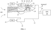
- the gas turbine engine 12 depicted in FIG. 1 , includes a compressor 14, combustion system 16, and a gas turbine 18.
- the compressor 14, combustion system 16, and gas turbine 18 are disposed around at least one of rotatable shaft 24. Atmospheric air enters the gas turbine engine 12 to be pressurized, heated and expelled to provide usable power output 30.
- Power output 30 can be provided to a power-driven machine or an associated power-generating machine, such as, but not limited to, an electric generator 20.
- the compressor 14 provides pressurized air to the combustion system 16.
- Fuel is provided to the combustion system 16 from a fuel system 22.
- the fuel can be mixed with pressurized air in a combustion chamber 40 to generate combustion gases and heat energy.
- the combustion gases flow away from combustion chamber 40 to gas turbine 18.
- the combustion gases flow through an annular array(s) of turbine blades 26, which are mounted on disks 28. These disks 28 rotate with a respective shaft 24.
- the rotation of each shaft 24 turns compressor 14, which in turn compresses the air to feed the combustion process.
- rotation of shaft 24 can also provide a power output 30 from gas turbine 18 to generator 20 or other system.
- combustion chamber 40 comprises a compressed air inlet duct, flow sleeve 42, and transition piece 44 or combustion gas exhaust duct to direct combustion air to gas turbine 18 (see FIG. 1 ).
- the flow sleeve 42 houses a combustion liner 46 and in turn combustion liner 46 defines a combustion zone 50.
- Combustion casing 48 attaches combustion chamber 40 to housing 32 of gas turbine engine 12, as illustrated in FIG. 2 .
- Combustion liner 46 is coaxially mounted within flow sleeve 42.
- Combustion liner 46 and flow sleeve 42 are both coaxially mounted within the combustor casing 48.
- Flow sleeve 42 is mounted in combustion casing 48 by any appropriate means, such as, but not limited to, mounting brackets.
- Combustion liner 46 comprises an inlet end that is generally aligned with a fuel nozzle. Combustion liner 46 also defines an exhaust end. The exhaust end is coupled to the transition piece 44 defining a flow passage for combustion gases from combustion zone 50 to first stage nozzle 64.
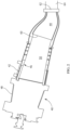
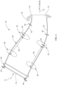
- Transition piece 44 depicted in FIGS. 3 , 4 and 5 , includes body 68 defining flowpath 72 and having generally circular inlet section 60 for receiving combustion products from combustion chamber 40 and generally rectilinear outlet end 62 for flowing the combustor products into first stage nozzle 64.
- Body 68 defines an enclosure 70 (see FIGS. 4 and 5 ) between inlet section 60 and outlet end 62 and enclosure 70 confines the flow of combustion products between inlet section 60 and outlet end 62.
- Transition piece 44 can be formed via a casting process in a one-piece or unitary construction.
- the terms "one-piece” or “unitary” construction as utilized herein, include components devoid of mechanical or metallurgical connections within the component, such as, but not limited to, brazing or welding, as evident in known transition piece configurations.
- transition piece 44 is not assembled from two or more components or parts, and is formed as a single part.
- transition piece 44 includes additional parts or pieces welded to the one-piece structure after transition piece 44 has been formed.
- transition piece 44 is formed from a nickel-based superalloy material, cobalt-based superalloy material, and combinations thereof.
- the superalloy material should provide sufficient material characteristics for operation at desired gas turbine operating conditions. These material properties include, but are not limited to, enhanced low cycle fatigue (LCF), enhanced resistance and creep strength vs. wrought alloys, enhanced manufacturability, improved machinability, enhanced weldability, and enhanced oxidation resistance.
- a nickel-based superalloy that provides such material characteristics is UDIMET ® alloy 500.
- UDIMET ® is a registered trademark of Special Metals Corporation, New Hartford, NY. This alloy is merely exemplary of a material that provides the desired material properties.
- the composition of UDIMET ® alloy 500 is provided in Table 1. TABLE 1 Composition of UDIMET ® 500 Carbon 0.15 max Aluminum 2.50-3.25 Titanium 2.5-3.25 Molybdenum 3.00-5.00 Chromium 15.00-20.00 Cobalt 13.00-20.00 Iron 4.00 max. Silicon 0.75 max. Manganese 0.75 max. Sulphur 0.015 max. Nickel Remainder
- the material of transition piece 44 provides desirable LCF resistance and creep strength of the material forming transition piece 44.
- the LCF resistance and creep strength are provided to extend life intervals of the material, where the life can be enhanced or extended by any amount of time.
- the nickel-based superalloy possesses strength characteristics at least conforming with, if not greater than, that of UDIMET ® alloy 500.
- a one-piece or unitary transition piece 44 includes thick transitions 80 and thin transitions 82. Thick transitions 80 occur at areas where there is a change in direction of mold to cast transition piece 44 to provide desired taper. Transition piece 44 includes a wall thickness 84 that changes along length of wall. Wall thickness 84 of thin transitions 82 is approximately 2.54 millimeters (0.100 inches) to approximately 5.08 millimeters (0.250 inches) or alternatively 2.75 millimeters (0.108 inches) to approximately 4.75 millimeters (0.187 inches) or alternatively approximately 3.0 millimeters (0.118 inches) to approximately 4.0 millimeters (0.157 inches). Wall thickness 84 of thick transitions 80 is greater than thin transitions 82 and generally approximately 1.1 to approximately 2.5 times greater than wall thickness 84 of thin transitions 82.
- the distance or length 86 between thick transition 80 - thin transition 82 - thick transition 80 is shown by the line labeled 86.
- the diameter of transition piece 44 is shown by the line labeled 74.
- One-piece cast transition piece 44 is formed using a taper ratio. Taper ratio is calculated as function of thick-to-thin transition ratio over a length-to-diameter ratio of transition piece 44. Thick-to-thin transition ratio is a ratio of wall thickness 84 of thick transition 80 over wall thickness 84 of thin transition 82.
- the thick-to-thin transition ratio is approximately 1.1 to approximately 2.5 or alternatively approximately 1.3 to approximately 2.2 or alternatively approximately 1.4 to approximately 2.0.
- the length-to-diameter ratio uses the distance or length 86 between thick transition 80 - thin transition 82 - thick transition 80 over the diameter 74 of transition piece 44.
- Length-to-diameter ratio is approximately 0.1 to approximately 0.9 or alternatively approximately 0.3 to approximately 0.8 or alternatively approximately 0.5 to approximately 0.7.
- the one-piece cast transition piece 44 having a taper ratio of about 1.1 to about 2.5 over 0.1 to 0.9 is provided by temperature controlled casting processes.
- transition piece 44 includes gas turbine component hardware or pieces that were previously welded or otherwise connected to transition piece 44, as shown in FIGS. 2 and 3 . These component hardware or pieces can be cast integrally with transition piece 44.
- component hardware comprises multiple cast pieces integrally formed with the transition piece 44, without need for such component hardware being joined to turbine combustor components by mechanical or metallurgical connections within the component, such as but not limited to, brazing or welding.
- transition piece 44 is free from locations between the transition piece 44 and the component hardware/pieces where the material properties differ from remainder of transition piece 44.
- Transition piece 44 is formed as a unitary article with integrally cast and connected hardware pieces, where these connected hardware pieces have similar material properties as transition piece 44 as well as similar material properties at points where the connected cast pieces are attached to transition piece 44.
- the component hardware/pieces of the transition piece 44 may comprise dilution holes in the generally tubular body 68, mounting connectors 66, circular inlet section 60, and rectilinear outlet end 62. These component hardware/pieces are cast with the transition piece 44 and are cast in a form that is very close to the desired final shape. These other components are known as "near net shape components" require very little or no subsequent machining, after initial casting. Accordingly, by forming these other components to near net or final shape, little after casting processing is needed. Therefore, resulting in enhanced production of a transition piece 44.
- the material for the transition piece 44 provides enhanced LCF, enhanced resistance and creep strength, improved manufacturability, better machinability, enhanced weldability, and desirable oxidation resistance.
- Other cast nickel based gamma prime strengthened alloys are also viable candidates generally having strength characteristics that match or exceed those of UDIMET ® alloy 500. "Strength characteristics" herein includes at least LCF resistance, creep strength, yield strength and ultimate tensile strength, each of which can be determined using well-known tests.
- a method 600 of forming a one-piece cast transition piece 44 may include, in one embodiment, providing a transition piece pattern, step 601 (see FIG. 3 ).
- Method 600 includes dipping the transition piece pattern in a slurry material, step 603 to build up the slurry material, step 605.
- Method 600 includes firing the slurry material to arrive at a transition piece shell, step 607.
- Method 600 includes filling the transition piece shell with a molten metal, step 609.
- Method 600 includes solidifying the molten metal to form one-piece cast transition piece 44, step 611 (see FIG. 3 ).
- Method 600 includes removing the transition piece shell revealing the formed one-piece cast transition.
- a temperature controlled casting process is used.
- TCS Thermally Controlled Solidification
- PCC Precision Castparts Corporation
- the transition piece pattern comprises a wax, a foam, combinations thereof, or other suitable material that can be used to arrive at the desired transition piece shape.
- the slurry material used to form the transition piece shell is a ceramic or other suitable material.
- the molten material is a nickel-based superalloy, for example, but not limited to, UDIMET ® alloy 500.
- transition piece 44 includes a taper ratio of thick-to-thin While the invention has been described with reference to a preferred embodiment, it will be understood by those skilled in the art that various changes may be made and equivalents may be substituted for elements thereof without departing from the scope of the invention which is defined by the appended claims.
Landscapes
- Engineering & Computer Science (AREA)
- Mechanical Engineering (AREA)
- General Engineering & Computer Science (AREA)
- Turbine Rotor Nozzle Sealing (AREA)
- Paper (AREA)
- Engine Equipment That Uses Special Cycles (AREA)
- Powder Metallurgy (AREA)
Applications Claiming Priority (1)
| Application Number | Priority Date | Filing Date | Title |
|---|---|---|---|
| US13/454,785 US9109447B2 (en) | 2012-04-24 | 2012-04-24 | Combustion system including a transition piece and method of forming using a cast superalloy |
Publications (3)
| Publication Number | Publication Date |
|---|---|
| EP2657453A2 EP2657453A2 (en) | 2013-10-30 |
| EP2657453A3 EP2657453A3 (en) | 2018-03-28 |
| EP2657453B1 true EP2657453B1 (en) | 2023-05-31 |
Family
ID=48139842
Family Applications (1)
| Application Number | Title | Priority Date | Filing Date |
|---|---|---|---|
| EP13164742.2A Active EP2657453B1 (en) | 2012-04-24 | 2013-04-22 | Transition piece for a gas turbine engine |
Country Status (5)
| Country | Link |
|---|---|
| US (1) | US9109447B2 (enExample) |
| EP (1) | EP2657453B1 (enExample) |
| JP (1) | JP6130714B2 (enExample) |
| CN (1) | CN103375187B (enExample) |
| RU (1) | RU2013118656A (enExample) |
Families Citing this family (3)
| Publication number | Priority date | Publication date | Assignee | Title |
|---|---|---|---|---|
| EP2915957A1 (en) * | 2014-03-05 | 2015-09-09 | Siemens Aktiengesellschaft | Cast tubular duct for a gas turbine and manufacturing method thereof |
| US10830142B2 (en) * | 2016-10-10 | 2020-11-10 | General Electric Company | Combustor aft frame cooling |
| CN107178792A (zh) * | 2017-06-13 | 2017-09-19 | 东方电气集团东方汽轮机有限公司 | 一种燃气轮机及航空发动机燃烧器尾筒结构 |
Family Cites Families (25)
| Publication number | Priority date | Publication date | Assignee | Title |
|---|---|---|---|---|
| US3527285A (en) | 1967-11-07 | 1970-09-08 | Gen Motors Corp | Method and mold for casting thin wall cylinders |
| US3657882A (en) * | 1970-11-13 | 1972-04-25 | Westinghouse Electric Corp | Combustion apparatus |
| US6416596B1 (en) | 1974-07-17 | 2002-07-09 | The General Electric Company | Cast nickel-base alloy |
| US4236378A (en) | 1978-03-01 | 1980-12-02 | General Electric Company | Sectoral combustor for burning low-BTU fuel gas |
| US4422288A (en) * | 1981-03-02 | 1983-12-27 | General Electric Company | Aft mounting system for combustion transition duct members |
| US5335502A (en) | 1992-09-09 | 1994-08-09 | General Electric Company | Arched combustor |
| US5414999A (en) | 1993-11-05 | 1995-05-16 | General Electric Company | Integral aft frame mount for a gas turbine combustor transition piece |
| JP3756994B2 (ja) * | 1995-07-11 | 2006-03-22 | 株式会社日立製作所 | ガスタービン用燃焼器及びガスタービン並びにその部材 |
| US5964091A (en) * | 1995-07-11 | 1999-10-12 | Hitachi, Ltd. | Gas turbine combustor and gas turbine |
| JPH10226838A (ja) * | 1997-02-19 | 1998-08-25 | Hitachi Metals Ltd | 燃焼器用鋳造部品およびその製造方法 |
| JP4097233B2 (ja) * | 1997-05-07 | 2008-06-11 | 株式会社東芝 | X線管の収容容器およびその製造方法、並びにx線管装置 |
| WO1999006771A1 (en) | 1997-07-31 | 1999-02-11 | Alliedsignal Inc. | Rib turbulators for combustor external cooling |
| US6553767B2 (en) | 2001-06-11 | 2003-04-29 | General Electric Company | Gas turbine combustor liner with asymmetric dilution holes machined from a single piece form |
| US6851263B2 (en) | 2002-10-29 | 2005-02-08 | General Electric Company | Liner for a gas turbine engine combustor having trapped vortex cavity |
| US6890148B2 (en) * | 2003-08-28 | 2005-05-10 | Siemens Westinghouse Power Corporation | Transition duct cooling system |
| US7373772B2 (en) | 2004-03-17 | 2008-05-20 | General Electric Company | Turbine combustor transition piece having dilution holes |
| US7082766B1 (en) * | 2005-03-02 | 2006-08-01 | General Electric Company | One-piece can combustor |
| US7377117B2 (en) | 2005-08-09 | 2008-05-27 | Turbine Services, Ltd. | Transition piece for gas turbine |
| US7540156B2 (en) | 2005-11-21 | 2009-06-02 | General Electric Company | Combustion liner for gas turbine formed of cast nickel-based superalloy |
| US7631504B2 (en) * | 2006-02-21 | 2009-12-15 | General Electric Company | Methods and apparatus for assembling gas turbine engines |
| US7908867B2 (en) * | 2007-09-14 | 2011-03-22 | Siemens Energy, Inc. | Wavy CMC wall hybrid ceramic apparatus |
| US20090249791A1 (en) * | 2008-04-08 | 2009-10-08 | General Electric Company | Transition piece impingement sleeve and method of assembly |
| US8549861B2 (en) | 2009-01-07 | 2013-10-08 | General Electric Company | Method and apparatus to enhance transition duct cooling in a gas turbine engine |
| US8397511B2 (en) * | 2009-05-19 | 2013-03-19 | General Electric Company | System and method for cooling a wall of a gas turbine combustor |
| US8226886B2 (en) * | 2009-08-31 | 2012-07-24 | General Electric Company | Nickel-based superalloys and articles |
-
2012
- 2012-04-24 US US13/454,785 patent/US9109447B2/en active Active
-
2013
- 2013-04-19 JP JP2013087923A patent/JP6130714B2/ja active Active
- 2013-04-22 EP EP13164742.2A patent/EP2657453B1/en active Active
- 2013-04-23 RU RU2013118656/06A patent/RU2013118656A/ru not_active Application Discontinuation
- 2013-04-24 CN CN201310145765.XA patent/CN103375187B/zh active Active
Also Published As
| Publication number | Publication date |
|---|---|
| RU2013118656A (ru) | 2014-10-27 |
| CN103375187B (zh) | 2016-11-23 |
| JP2013227973A (ja) | 2013-11-07 |
| CN103375187A (zh) | 2013-10-30 |
| JP6130714B2 (ja) | 2017-05-17 |
| EP2657453A2 (en) | 2013-10-30 |
| US20130276451A1 (en) | 2013-10-24 |
| EP2657453A3 (en) | 2018-03-28 |
| US9109447B2 (en) | 2015-08-18 |
Similar Documents
| Publication | Publication Date | Title |
|---|---|---|
| CA2645380C (en) | Monolithic and bi-metallic turbine blade dampers and method of manufacture | |
| CN106121736B (zh) | 利用无热应力的紧固件的涡轮构件连接 | |
| US7540156B2 (en) | Combustion liner for gas turbine formed of cast nickel-based superalloy | |
| EP1927722B1 (en) | Rotary assembly components and methods of fabricating such components | |
| US20160273368A1 (en) | Blade of a turbomachine made of different materials and method for the production thereof | |
| US20070163114A1 (en) | Methods for fabricating components | |
| JP2012507624A (ja) | 溶接添加剤、溶接添加剤の使用並びにコンポーネント | |
| JP2011073060A (ja) | 集束エネルギーロウ付けのための方法及びシステム | |
| US10053988B2 (en) | Article and method of forming an article | |
| US10822963B2 (en) | Axial flow cooling scheme with castable structural rib for a gas turbine engine | |
| US20160186579A1 (en) | HYBRID GAMMA TiAl ALLOY COMPONENT | |
| US9243514B2 (en) | Hybrid gas turbine bearing support | |
| EP2795067B1 (en) | Method for manufacturing of a gas turbine engine component | |
| CN108977698A (zh) | 使用增材制造替换试件修复部件的方法和用于增材制造的合金 | |
| EP2657453B1 (en) | Transition piece for a gas turbine engine | |
| JP3756994B2 (ja) | ガスタービン用燃焼器及びガスタービン並びにその部材 | |
| EP3663524B1 (en) | Axial flow cooling scheme with structural rib for a gas turbine engine | |
| JP2018185135A (ja) | 構成要素用の冷却構造を設ける方法 | |
| CA2669582A1 (en) | Vane ring, and method for the production thereof | |
| EP2666962A2 (en) | A sectioned rotor, a steam turbine having a sectioned rotor and a method for producing a sectioned rotor | |
| US7681623B2 (en) | Casting process and cast component | |
| JP3991510B2 (ja) | 高温ガスタービン | |
| US20130101431A1 (en) | Rotor, a steam turbine and a method for producing a rotor | |
| JPH07286730A (ja) | ガスタービン燃焼器用保炎器 | |
| Tosnar | High–temperature brazing and EB–welding in the construction of Walter turbojet engines |
Legal Events
| Date | Code | Title | Description |
|---|---|---|---|
| PUAI | Public reference made under article 153(3) epc to a published international application that has entered the european phase |
Free format text: ORIGINAL CODE: 0009012 |
|
| AK | Designated contracting states |
Kind code of ref document: A2 Designated state(s): AL AT BE BG CH CY CZ DE DK EE ES FI FR GB GR HR HU IE IS IT LI LT LU LV MC MK MT NL NO PL PT RO RS SE SI SK SM TR |
|
| AX | Request for extension of the european patent |
Extension state: BA ME |
|
| PUAL | Search report despatched |
Free format text: ORIGINAL CODE: 0009013 |
|
| AK | Designated contracting states |
Kind code of ref document: A3 Designated state(s): AL AT BE BG CH CY CZ DE DK EE ES FI FR GB GR HR HU IE IS IT LI LT LU LV MC MK MT NL NO PL PT RO RS SE SI SK SM TR |
|
| AX | Request for extension of the european patent |
Extension state: BA ME |
|
| RIC1 | Information provided on ipc code assigned before grant |
Ipc: B22D 21/02 20060101ALI20180217BHEP Ipc: F01D 9/02 20060101AFI20180217BHEP Ipc: B22C 9/04 20060101ALI20180217BHEP Ipc: B22D 19/04 20060101ALI20180217BHEP |
|
| STAA | Information on the status of an ep patent application or granted ep patent |
Free format text: STATUS: REQUEST FOR EXAMINATION WAS MADE |
|
| 17P | Request for examination filed |
Effective date: 20180928 |
|
| RBV | Designated contracting states (corrected) |
Designated state(s): AL AT BE BG CH CY CZ DE DK EE ES FI FR GB GR HR HU IE IS IT LI LT LU LV MC MK MT NL NO PL PT RO RS SE SI SK SM TR |
|
| STAA | Information on the status of an ep patent application or granted ep patent |
Free format text: STATUS: EXAMINATION IS IN PROGRESS |
|
| 17Q | First examination report despatched |
Effective date: 20190211 |
|
| GRAP | Despatch of communication of intention to grant a patent |
Free format text: ORIGINAL CODE: EPIDOSNIGR1 |
|
| STAA | Information on the status of an ep patent application or granted ep patent |
Free format text: STATUS: GRANT OF PATENT IS INTENDED |
|
| INTG | Intention to grant announced |
Effective date: 20230317 |
|
| GRAS | Grant fee paid |
Free format text: ORIGINAL CODE: EPIDOSNIGR3 |
|
| GRAA | (expected) grant |
Free format text: ORIGINAL CODE: 0009210 |
|
| STAA | Information on the status of an ep patent application or granted ep patent |
Free format text: STATUS: THE PATENT HAS BEEN GRANTED |
|
| AK | Designated contracting states |
Kind code of ref document: B1 Designated state(s): AL AT BE BG CH CY CZ DE DK EE ES FI FR GB GR HR HU IE IS IT LI LT LU LV MC MK MT NL NO PL PT RO RS SE SI SK SM TR |
|
| REG | Reference to a national code |
Ref country code: GB Ref legal event code: FG4D Ref country code: CH Ref legal event code: EP |
|
| REG | Reference to a national code |
Ref country code: AT Ref legal event code: REF Ref document number: 1571022 Country of ref document: AT Kind code of ref document: T Effective date: 20230615 Ref country code: DE Ref legal event code: R096 Ref document number: 602013083860 Country of ref document: DE |
|
| REG | Reference to a national code |
Ref country code: IE Ref legal event code: FG4D |
|
| REG | Reference to a national code |
Ref country code: LT Ref legal event code: MG9D |
|
| REG | Reference to a national code |
Ref country code: NL Ref legal event code: MP Effective date: 20230531 |
|
| REG | Reference to a national code |
Ref country code: AT Ref legal event code: MK05 Ref document number: 1571022 Country of ref document: AT Kind code of ref document: T Effective date: 20230531 |
|
| PG25 | Lapsed in a contracting state [announced via postgrant information from national office to epo] |
Ref country code: SE Free format text: LAPSE BECAUSE OF FAILURE TO SUBMIT A TRANSLATION OF THE DESCRIPTION OR TO PAY THE FEE WITHIN THE PRESCRIBED TIME-LIMIT Effective date: 20230531 Ref country code: NO Free format text: LAPSE BECAUSE OF FAILURE TO SUBMIT A TRANSLATION OF THE DESCRIPTION OR TO PAY THE FEE WITHIN THE PRESCRIBED TIME-LIMIT Effective date: 20230831 Ref country code: ES Free format text: LAPSE BECAUSE OF FAILURE TO SUBMIT A TRANSLATION OF THE DESCRIPTION OR TO PAY THE FEE WITHIN THE PRESCRIBED TIME-LIMIT Effective date: 20230531 Ref country code: AT Free format text: LAPSE BECAUSE OF FAILURE TO SUBMIT A TRANSLATION OF THE DESCRIPTION OR TO PAY THE FEE WITHIN THE PRESCRIBED TIME-LIMIT Effective date: 20230531 |
|
| REG | Reference to a national code |
Ref country code: DE Ref legal event code: R081 Ref document number: 602013083860 Country of ref document: DE Owner name: GENERAL ELECTRIC TECHNOLOGY GMBH, CH Free format text: FORMER OWNER: GENERAL ELECTRIC COMPANY, SCHENECTADY, NY, US |
|
| PG25 | Lapsed in a contracting state [announced via postgrant information from national office to epo] |
Ref country code: RS Free format text: LAPSE BECAUSE OF FAILURE TO SUBMIT A TRANSLATION OF THE DESCRIPTION OR TO PAY THE FEE WITHIN THE PRESCRIBED TIME-LIMIT Effective date: 20230531 Ref country code: PL Free format text: LAPSE BECAUSE OF FAILURE TO SUBMIT A TRANSLATION OF THE DESCRIPTION OR TO PAY THE FEE WITHIN THE PRESCRIBED TIME-LIMIT Effective date: 20230531 Ref country code: NL Free format text: LAPSE BECAUSE OF FAILURE TO SUBMIT A TRANSLATION OF THE DESCRIPTION OR TO PAY THE FEE WITHIN THE PRESCRIBED TIME-LIMIT Effective date: 20230531 Ref country code: LV Free format text: LAPSE BECAUSE OF FAILURE TO SUBMIT A TRANSLATION OF THE DESCRIPTION OR TO PAY THE FEE WITHIN THE PRESCRIBED TIME-LIMIT Effective date: 20230531 Ref country code: LT Free format text: LAPSE BECAUSE OF FAILURE TO SUBMIT A TRANSLATION OF THE DESCRIPTION OR TO PAY THE FEE WITHIN THE PRESCRIBED TIME-LIMIT Effective date: 20230531 Ref country code: IS Free format text: LAPSE BECAUSE OF FAILURE TO SUBMIT A TRANSLATION OF THE DESCRIPTION OR TO PAY THE FEE WITHIN THE PRESCRIBED TIME-LIMIT Effective date: 20230930 Ref country code: HR Free format text: LAPSE BECAUSE OF FAILURE TO SUBMIT A TRANSLATION OF THE DESCRIPTION OR TO PAY THE FEE WITHIN THE PRESCRIBED TIME-LIMIT Effective date: 20230531 Ref country code: GR Free format text: LAPSE BECAUSE OF FAILURE TO SUBMIT A TRANSLATION OF THE DESCRIPTION OR TO PAY THE FEE WITHIN THE PRESCRIBED TIME-LIMIT Effective date: 20230901 |
|
| RAP2 | Party data changed (patent owner data changed or rights of a patent transferred) |
Owner name: GENERAL ELECTRIC TECHNOLOGY GMBH |
|
| PG25 | Lapsed in a contracting state [announced via postgrant information from national office to epo] |
Ref country code: FI Free format text: LAPSE BECAUSE OF FAILURE TO SUBMIT A TRANSLATION OF THE DESCRIPTION OR TO PAY THE FEE WITHIN THE PRESCRIBED TIME-LIMIT Effective date: 20230531 |
|
| PG25 | Lapsed in a contracting state [announced via postgrant information from national office to epo] |
Ref country code: SK Free format text: LAPSE BECAUSE OF FAILURE TO SUBMIT A TRANSLATION OF THE DESCRIPTION OR TO PAY THE FEE WITHIN THE PRESCRIBED TIME-LIMIT Effective date: 20230531 |
|
| PG25 | Lapsed in a contracting state [announced via postgrant information from national office to epo] |
Ref country code: SM Free format text: LAPSE BECAUSE OF FAILURE TO SUBMIT A TRANSLATION OF THE DESCRIPTION OR TO PAY THE FEE WITHIN THE PRESCRIBED TIME-LIMIT Effective date: 20230531 Ref country code: SK Free format text: LAPSE BECAUSE OF FAILURE TO SUBMIT A TRANSLATION OF THE DESCRIPTION OR TO PAY THE FEE WITHIN THE PRESCRIBED TIME-LIMIT Effective date: 20230531 Ref country code: RO Free format text: LAPSE BECAUSE OF FAILURE TO SUBMIT A TRANSLATION OF THE DESCRIPTION OR TO PAY THE FEE WITHIN THE PRESCRIBED TIME-LIMIT Effective date: 20230531 Ref country code: PT Free format text: LAPSE BECAUSE OF FAILURE TO SUBMIT A TRANSLATION OF THE DESCRIPTION OR TO PAY THE FEE WITHIN THE PRESCRIBED TIME-LIMIT Effective date: 20231002 Ref country code: EE Free format text: LAPSE BECAUSE OF FAILURE TO SUBMIT A TRANSLATION OF THE DESCRIPTION OR TO PAY THE FEE WITHIN THE PRESCRIBED TIME-LIMIT Effective date: 20230531 Ref country code: DK Free format text: LAPSE BECAUSE OF FAILURE TO SUBMIT A TRANSLATION OF THE DESCRIPTION OR TO PAY THE FEE WITHIN THE PRESCRIBED TIME-LIMIT Effective date: 20230531 Ref country code: CZ Free format text: LAPSE BECAUSE OF FAILURE TO SUBMIT A TRANSLATION OF THE DESCRIPTION OR TO PAY THE FEE WITHIN THE PRESCRIBED TIME-LIMIT Effective date: 20230531 |
|
| REG | Reference to a national code |
Ref country code: DE Ref legal event code: R097 Ref document number: 602013083860 Country of ref document: DE |
|
| PLBE | No opposition filed within time limit |
Free format text: ORIGINAL CODE: 0009261 |
|
| STAA | Information on the status of an ep patent application or granted ep patent |
Free format text: STATUS: NO OPPOSITION FILED WITHIN TIME LIMIT |
|
| PG25 | Lapsed in a contracting state [announced via postgrant information from national office to epo] |
Ref country code: SI Free format text: LAPSE BECAUSE OF FAILURE TO SUBMIT A TRANSLATION OF THE DESCRIPTION OR TO PAY THE FEE WITHIN THE PRESCRIBED TIME-LIMIT Effective date: 20230531 |
|
| 26N | No opposition filed |
Effective date: 20240301 |
|
| PG25 | Lapsed in a contracting state [announced via postgrant information from national office to epo] |
Ref country code: SI Free format text: LAPSE BECAUSE OF FAILURE TO SUBMIT A TRANSLATION OF THE DESCRIPTION OR TO PAY THE FEE WITHIN THE PRESCRIBED TIME-LIMIT Effective date: 20230531 Ref country code: IT Free format text: LAPSE BECAUSE OF FAILURE TO SUBMIT A TRANSLATION OF THE DESCRIPTION OR TO PAY THE FEE WITHIN THE PRESCRIBED TIME-LIMIT Effective date: 20230531 |
|
| PG25 | Lapsed in a contracting state [announced via postgrant information from national office to epo] |
Ref country code: BG Free format text: LAPSE BECAUSE OF FAILURE TO SUBMIT A TRANSLATION OF THE DESCRIPTION OR TO PAY THE FEE WITHIN THE PRESCRIBED TIME-LIMIT Effective date: 20230531 |
|
| PG25 | Lapsed in a contracting state [announced via postgrant information from national office to epo] |
Ref country code: MC Free format text: LAPSE BECAUSE OF FAILURE TO SUBMIT A TRANSLATION OF THE DESCRIPTION OR TO PAY THE FEE WITHIN THE PRESCRIBED TIME-LIMIT Effective date: 20230531 |
|
| PG25 | Lapsed in a contracting state [announced via postgrant information from national office to epo] |
Ref country code: MC Free format text: LAPSE BECAUSE OF FAILURE TO SUBMIT A TRANSLATION OF THE DESCRIPTION OR TO PAY THE FEE WITHIN THE PRESCRIBED TIME-LIMIT Effective date: 20230531 Ref country code: BG Free format text: LAPSE BECAUSE OF FAILURE TO SUBMIT A TRANSLATION OF THE DESCRIPTION OR TO PAY THE FEE WITHIN THE PRESCRIBED TIME-LIMIT Effective date: 20230531 |
|
| REG | Reference to a national code |
Ref country code: CH Ref legal event code: PL |
|
| PG25 | Lapsed in a contracting state [announced via postgrant information from national office to epo] |
Ref country code: LU Free format text: LAPSE BECAUSE OF NON-PAYMENT OF DUE FEES Effective date: 20240422 |
|
| GBPC | Gb: european patent ceased through non-payment of renewal fee |
Effective date: 20240422 |
|
| REG | Reference to a national code |
Ref country code: BE Ref legal event code: MM Effective date: 20240430 |
|
| PG25 | Lapsed in a contracting state [announced via postgrant information from national office to epo] |
Ref country code: LU Free format text: LAPSE BECAUSE OF NON-PAYMENT OF DUE FEES Effective date: 20240422 |
|
| PG25 | Lapsed in a contracting state [announced via postgrant information from national office to epo] |
Ref country code: BE Free format text: LAPSE BECAUSE OF NON-PAYMENT OF DUE FEES Effective date: 20240430 |
|
| PG25 | Lapsed in a contracting state [announced via postgrant information from national office to epo] |
Ref country code: GB Free format text: LAPSE BECAUSE OF NON-PAYMENT OF DUE FEES Effective date: 20240422 |
|
| PG25 | Lapsed in a contracting state [announced via postgrant information from national office to epo] |
Ref country code: FR Free format text: LAPSE BECAUSE OF NON-PAYMENT OF DUE FEES Effective date: 20240430 |
|
| PG25 | Lapsed in a contracting state [announced via postgrant information from national office to epo] |
Ref country code: GB Free format text: LAPSE BECAUSE OF NON-PAYMENT OF DUE FEES Effective date: 20240422 Ref country code: FR Free format text: LAPSE BECAUSE OF NON-PAYMENT OF DUE FEES Effective date: 20240430 Ref country code: BE Free format text: LAPSE BECAUSE OF NON-PAYMENT OF DUE FEES Effective date: 20240430 Ref country code: CH Free format text: LAPSE BECAUSE OF NON-PAYMENT OF DUE FEES Effective date: 20240430 |
|
| PG25 | Lapsed in a contracting state [announced via postgrant information from national office to epo] |
Ref country code: IE Free format text: LAPSE BECAUSE OF NON-PAYMENT OF DUE FEES Effective date: 20240422 |
|
| PGFP | Annual fee paid to national office [announced via postgrant information from national office to epo] |
Ref country code: DE Payment date: 20250319 Year of fee payment: 13 |
|
| PG25 | Lapsed in a contracting state [announced via postgrant information from national office to epo] |
Ref country code: CY Free format text: LAPSE BECAUSE OF FAILURE TO SUBMIT A TRANSLATION OF THE DESCRIPTION OR TO PAY THE FEE WITHIN THE PRESCRIBED TIME-LIMIT; INVALID AB INITIO Effective date: 20130422 |
|
| PG25 | Lapsed in a contracting state [announced via postgrant information from national office to epo] |
Ref country code: HU Free format text: LAPSE BECAUSE OF FAILURE TO SUBMIT A TRANSLATION OF THE DESCRIPTION OR TO PAY THE FEE WITHIN THE PRESCRIBED TIME-LIMIT; INVALID AB INITIO Effective date: 20130422 |