EP2656633B1 - Device and method for calculating speaker signals for a plurality of speakers using a delay in the frequency domain - Google Patents
Device and method for calculating speaker signals for a plurality of speakers using a delay in the frequency domain Download PDFInfo
- Publication number
- EP2656633B1 EP2656633B1 EP12816679.0A EP12816679A EP2656633B1 EP 2656633 B1 EP2656633 B1 EP 2656633B1 EP 12816679 A EP12816679 A EP 12816679A EP 2656633 B1 EP2656633 B1 EP 2656633B1
- Authority
- EP
- European Patent Office
- Prior art keywords
- loudspeaker
- short
- delay
- filter
- stage
- Prior art date
- Legal status (The legal status is an assumption and is not a legal conclusion. Google has not performed a legal analysis and makes no representation as to the accuracy of the status listed.)
- Active
Links
- 238000000034 method Methods 0.000 title claims description 72
- 238000001228 spectrum Methods 0.000 claims description 117
- 230000005236 sound signal Effects 0.000 claims description 75
- 230000004044 response Effects 0.000 claims description 58
- 238000004422 calculation algorithm Methods 0.000 claims description 53
- 230000015572 biosynthetic process Effects 0.000 claims description 51
- 238000003786 synthesis reaction Methods 0.000 claims description 51
- 230000006870 function Effects 0.000 claims description 21
- 238000001914 filtration Methods 0.000 claims description 17
- 230000003595 spectral effect Effects 0.000 claims description 9
- 230000002123 temporal effect Effects 0.000 claims description 9
- 238000004590 computer program Methods 0.000 claims description 6
- 230000005540 biological transmission Effects 0.000 claims description 4
- 230000001131 transforming effect Effects 0.000 claims 2
- 238000005192 partition Methods 0.000 claims 1
- 238000012545 processing Methods 0.000 description 43
- 238000004364 calculation method Methods 0.000 description 20
- 230000009466 transformation Effects 0.000 description 20
- 238000005070 sampling Methods 0.000 description 13
- 238000009877 rendering Methods 0.000 description 12
- 230000001934 delay Effects 0.000 description 11
- 230000003068 static effect Effects 0.000 description 10
- 230000001419 dependent effect Effects 0.000 description 9
- 238000007792 addition Methods 0.000 description 8
- 230000000694 effects Effects 0.000 description 7
- 238000013461 design Methods 0.000 description 6
- 230000005404 monopole Effects 0.000 description 6
- 238000013459 approach Methods 0.000 description 5
- 238000005516 engineering process Methods 0.000 description 5
- 238000000638 solvent extraction Methods 0.000 description 5
- 239000013598 vector Substances 0.000 description 5
- 238000003491 array Methods 0.000 description 4
- 125000004122 cyclic group Chemical group 0.000 description 4
- 230000003179 granulation Effects 0.000 description 4
- 238000005469 granulation Methods 0.000 description 4
- 230000008569 process Effects 0.000 description 4
- 230000008901 benefit Effects 0.000 description 3
- 230000006872 improvement Effects 0.000 description 3
- 230000000737 periodic effect Effects 0.000 description 3
- 238000012546 transfer Methods 0.000 description 3
- 230000006399 behavior Effects 0.000 description 2
- 230000000052 comparative effect Effects 0.000 description 2
- 238000006073 displacement reaction Methods 0.000 description 2
- 238000003780 insertion Methods 0.000 description 2
- 230000037431 insertion Effects 0.000 description 2
- 238000000844 transformation Methods 0.000 description 2
- 230000001133 acceleration Effects 0.000 description 1
- 230000009471 action Effects 0.000 description 1
- 238000004458 analytical method Methods 0.000 description 1
- 238000000429 assembly Methods 0.000 description 1
- 230000000712 assembly Effects 0.000 description 1
- 230000000903 blocking effect Effects 0.000 description 1
- 230000008859 change Effects 0.000 description 1
- 235000009508 confectionery Nutrition 0.000 description 1
- 238000000354 decomposition reaction Methods 0.000 description 1
- 230000003111 delayed effect Effects 0.000 description 1
- 238000009795 derivation Methods 0.000 description 1
- 230000001627 detrimental effect Effects 0.000 description 1
- 238000010586 diagram Methods 0.000 description 1
- 230000007613 environmental effect Effects 0.000 description 1
- 238000002474 experimental method Methods 0.000 description 1
- 238000009434 installation Methods 0.000 description 1
- 238000013507 mapping Methods 0.000 description 1
- 230000007334 memory performance Effects 0.000 description 1
- 230000004048 modification Effects 0.000 description 1
- 238000012986 modification Methods 0.000 description 1
- 231100000989 no adverse effect Toxicity 0.000 description 1
- 238000005457 optimization Methods 0.000 description 1
- 230000010363 phase shift Effects 0.000 description 1
- 230000008092 positive effect Effects 0.000 description 1
- 238000011045 prefiltration Methods 0.000 description 1
- 238000013139 quantization Methods 0.000 description 1
- 230000009467 reduction Effects 0.000 description 1
- 230000001052 transient effect Effects 0.000 description 1
Images


Classifications
-
- G—PHYSICS
- G10—MUSICAL INSTRUMENTS; ACOUSTICS
- G10L—SPEECH ANALYSIS OR SYNTHESIS; SPEECH RECOGNITION; SPEECH OR VOICE PROCESSING; SPEECH OR AUDIO CODING OR DECODING
- G10L19/00—Speech or audio signals analysis-synthesis techniques for redundancy reduction, e.g. in vocoders; Coding or decoding of speech or audio signals, using source filter models or psychoacoustic analysis
- G10L19/04—Speech or audio signals analysis-synthesis techniques for redundancy reduction, e.g. in vocoders; Coding or decoding of speech or audio signals, using source filter models or psychoacoustic analysis using predictive techniques
- G10L19/26—Pre-filtering or post-filtering
-
- H—ELECTRICITY
- H04—ELECTRIC COMMUNICATION TECHNIQUE
- H04R—LOUDSPEAKERS, MICROPHONES, GRAMOPHONE PICK-UPS OR LIKE ACOUSTIC ELECTROMECHANICAL TRANSDUCERS; DEAF-AID SETS; PUBLIC ADDRESS SYSTEMS
- H04R29/00—Monitoring arrangements; Testing arrangements
- H04R29/001—Monitoring arrangements; Testing arrangements for loudspeakers
-
- H—ELECTRICITY
- H04—ELECTRIC COMMUNICATION TECHNIQUE
- H04R—LOUDSPEAKERS, MICROPHONES, GRAMOPHONE PICK-UPS OR LIKE ACOUSTIC ELECTROMECHANICAL TRANSDUCERS; DEAF-AID SETS; PUBLIC ADDRESS SYSTEMS
- H04R3/00—Circuits for transducers, loudspeakers or microphones
- H04R3/12—Circuits for transducers, loudspeakers or microphones for distributing signals to two or more loudspeakers
-
- H—ELECTRICITY
- H04—ELECTRIC COMMUNICATION TECHNIQUE
- H04R—LOUDSPEAKERS, MICROPHONES, GRAMOPHONE PICK-UPS OR LIKE ACOUSTIC ELECTROMECHANICAL TRANSDUCERS; DEAF-AID SETS; PUBLIC ADDRESS SYSTEMS
- H04R2430/00—Signal processing covered by H04R, not provided for in its groups
- H04R2430/03—Synergistic effects of band splitting and sub-band processing
-
- H—ELECTRICITY
- H04—ELECTRIC COMMUNICATION TECHNIQUE
- H04S—STEREOPHONIC SYSTEMS
- H04S2420/00—Techniques used stereophonic systems covered by H04S but not provided for in its groups
- H04S2420/07—Synergistic effects of band splitting and sub-band processing
-
- H—ELECTRICITY
- H04—ELECTRIC COMMUNICATION TECHNIQUE
- H04S—STEREOPHONIC SYSTEMS
- H04S2420/00—Techniques used stereophonic systems covered by H04S but not provided for in its groups
- H04S2420/13—Application of wave-field synthesis in stereophonic audio systems
Definitions
- the present invention relates to an apparatus and a method for calculating loudspeaker signals for a plurality of loudspeakers using frequency-domain filtering, such as a wave-field synthesis renderer device and a method of operating such a device.
- WFS Wave Field Synthesis
- WFS The basic idea of WFS is based on the application of Huygens' principle of wave theory: every point, which is detected by a wave, is the starting point of an elementary wave, which spreads in a spherical or circular manner.
- Applied to the acoustics can be simulated by a large number of speakers, which are arranged side by side (a so-called speaker array), any sound field.
- the audio signal of each speaker is generated by the application of a so-called. WFS operator from the audio signal of the source.
- the WFS operator corresponds to an amplitude scaling and a time delay of the input signal.
- the application of this amplitude scaling and time delay is hereafter referred to as Scale & Delay.
- a time delay and amplitude scaling can be applied to the audio signal of each loudspeaker so that the radiated sound fields of the individual loudspeakers are properly superimposed.
- the contribution to each speaker is calculated separately for each source and the resulting signals added together. If the sources to be reproduced are in a room with reflective walls, reflections must also be reproduced as additional sources via the loudspeaker array. The cost of the calculation therefore depends heavily on the number of sound sources, the reflection characteristics of the recording room and the number of speakers.
- the advantage of this technique is in particular that a natural spatial sound impression over a large area of the playback room is possible.
- the direction and distance of sound sources are reproduced very accurately.
- virtual sound sources can even be positioned between the real speaker array and the listener.
- wave field synthesis provides good, if the assumed assumptions in theory, such as ideal speaker characteristics, regular, gapless speaker arrays or free field conditions for sound propagation are at least approximately fulfilled. In practice, however, these conditions are often violated, for. B. by incomplete speaker arrays or a significant influence of room acoustics.
- An environmental condition can be described by the impulse response of the environment.
- the space compensation using wavefield synthesis would be to first determine the reflection of that wall to determine when a sound signal reflected from the wall will return to the loudspeaker and what amplitude this reflected sound signal will be Has. If the reflection from this wall is undesirable, then with the wave field synthesis it is possible to eliminate the reflection from this wall by impressing the loudspeaker with a signal of opposite amplitude to the reflection signal in addition to the original audio signal, so that the traveling compensating wave is the Reflectance wave extinguished, so that the reflection from this wall in the environment that is considered, is eliminated. This can be done by first computing the impulse response of the environment and determining the nature and position of the wall based on the impulse response of that environment. In this case, the sound reflected by the wall is represented by an additional WFS sound source, a so-called mirror sound source, whose signal is generated by filtering and delay from the original source signal.
- Wave field synthesis thus allows a correct mapping of virtual sound sources over a large playback area. At the same time it offers the sound engineer and sound engineer new technical and creative potential in the creation of even complex soundscapes.
- Wave field synthesis as developed at the TU Delft in the late 1980s, represents a holographic approach to sound reproduction. The basis for this is the Kirchhoff-Helmholtz integral. This states that any sound fields within a closed volume are distributed by means of a distribution of monopoly and dipole sound sources (speaker arrays) can be created on the surface of this volume.
- a synthesis signal is calculated for each loudspeaker of the loudspeaker array, the synthesis signals being designed in amplitude and delay such that a wave resulting from the superimposition of the individual the sound wave present in the loudspeaker array will correspond to the wave that would result from the virtual source at the virtual position if that virtual source at the virtual position were a real source with a real position.
- multiple virtual sources exist at different virtual locations.
- the computation of the synthesis signals is performed for each virtual source at each virtual location, typically resulting in one virtual source in multiple speaker synthesis signals. Seen from a loudspeaker, this loudspeaker thus receives several synthesis signals, which go back to different virtual sources. A superimposition of these sources, which is possible due to the linear superposition principle, then gives the reproduced signal actually emitted by the speaker.
- the object of the present invention is to provide an efficient concept for calculating loudspeaker signals for a plurality of loudspeakers using audio sources.
- the present invention is advantageous in that it provides an efficient concept through the combination of an out-of-order stage, a memory, a memory access controller, a filter stage, a summer stage, and a re-transform stage, characterized in that the The number of round-trip transformation calculations need not be made for each individual audio source / speaker combination, but only for each individual audio source.
- the re-transformation need not be calculated for each individual audio-signal-speaker combination, but only for the number of speakers.
- the number of Hin-Transform calculations is equal to the number of audio sources and the number of reverse-transformation calculations is equal to the number of loudspeaker signals or loudspeakers to be driven when a loudspeaker signal drives a loudspeaker.
- the introduction of the delay in the frequency domain is achieved by a memory access control in an efficient manner by advantageously exploiting the feed used in the transformation based on a delay value for an audio signal / loudspeaker combination.
- the out-of-order stage provides a sequence of short-term spectra stored in memory for each audio signal.
- the memory access controller thus has access to a sequence of temporally successive short-term spectra.
- the short-term spectrum is selected from the sequence of short-term spectra that best matches the delay value provided by, for example, a wave field synthesis operator. For example, if the feed value in the calculation of the individual blocks of a short-term spectrum to the next short-term spectrum is 20 ms, and if the wave-field synthesis operator requires a delay of 100 ms, then this entire delay can easily be implemented by not having the most recent short-term spectrum in the memory for the audio / loudspeaker combination under consideration is used, but also stored fifth past spa time spectrum.
- the device according to the invention is already able to implement a delay solely on the basis of the stored short-term spectra in a certain grid, which is determined by the feed. If this grid is already sufficient for a particular application, no further action is required. However, if a finer delay control is needed, it can also be implemented in the frequency domain by using in the filtering stage to filter a particular short-term spectrum a filter whose impulse response has been manipulated with a certain number of zeros at the beginning of the filter impulse response. Thus, a finer delay granulation can be achieved, which does not take place now, as in the memory access control in periods according to the block feed, but now much finer in terms of a sampling period, ie the time interval between two samples.
- the delay can also be implemented in the filter stage by implementing the impulse response, which has already been supplemented with zeros, using a fractional delay filter.
- all the necessary delay values can be implemented in the frequency domain, that is to say between the Hin transformation and therut transformation, wherein the greatest proportion of the delay is achieved simply by a memory access control, in which case a granulation according to the block Feed is achieved or according to the time period corresponding to a block feed. If finer delays are needed, this finer delay is implemented by modifying the filter impulse response for each audio signal / speaker combination in the filter stage to insert zeros at the beginning of the impulse response.
- the present invention is particularly suitable for static sources because the static virtual sources also have static delay values for each audio-signal-speaker combination. Therefore, for every position of a virtual source the memory access control will be fixed.
- the impulse response for the particular loudspeaker audio signal combination in each individual block of the filter stage can be pre-set before the actual rendering algorithm is executed. For this purpose, the actually required for this audio signal speaker combination impulse response is changed so that a corresponding number of zeros at the beginning of the impulse response is inserted in order to achieve a finely resolved delay. Then this impulse response is transformed into the spectral range and stored there in a single filter. In the actual wave field synthesis rendering calculation, it is then always possible to resort to stored transfer functions of the individual filters in the individual filter blocks.
- a preferred wavefield synthesis renderer device or method for operating a wavefield synthesis renderer device comprises N virtual sound sources that provide sampling values for the source signals x 0 ... X N-1 , and a signal processing unit composed of the Source signals x 0 ... x N-1 Sampling values for M loudspeaker signals y 0 ... y M-1 generated, wherein in the signal processing unit for each source-speaker combination a filter spectrum is stored, each source signal x 0 ...
- x N-1 is transformed into the spectra with a plurality of FFT calculation blocks of block length L, the FFT calculation blocks having an overlap of length (LB) and a length B feed, multiplying each spectrum by the respective filter spectra of the same source is, from which the spectra are generated, the access to the spectra is such that the speakers each with a r predetermined delay corresponding to an integer multiple of the feed B, all spectra of the same speaker i are added, from which the spectra Q j are generated, and each spectrum Q j with an IFFT calculation block in the sampling values for the M loudspeaker signals y 0 ... y M-1 is transformed.
- the block-by-block shift of the individual spectra can be exploited to generate a delay of the loudspeaker signals y 0 ... Y M-1 by a targeted access to the spectra.
- the computational effort for this delay depends only on the targeted access to the spectra, so that no additional computing power is required for the introduction of delays, as long as the delay corresponds to an integer multiple of the feed B.
- the invention thus relates to the wave field synthesis of Richteten sound sources or sound sources with directional characteristics.
- WFS setups which consist of multiple virtual sources and a large number of speakers, the need to apply individual FIR filters for each combination of virtual source and loudspeaker often prevents easy implementation.
- the invention proposes an efficient processing structure based on time / frequency techniques.
- Combining the components of a fast convolution algorithm into the structure of a WFS rendering system allows the efficient reuse of operations and intermediate results, and thus a significant increase in efficiency.
- the potential acceleration increases with the number of virtual sources and speakers, significant savings are also made for moderate-size WFS assemblies.
- the performance gains are relatively consistent for a wide variety of parameter choices for the filter size and block delay value.
- the handling of time delays which is an inherent requirement of sound reproduction techniques, such as e.g. WFS requires a modification of the overlap-save technique. This is efficiently solved by partitioning the delay value and using frequency-domain delay lines or frequency-line-implemented delay lines.
- the invention is thus not limited to the processing of directional sound sources or directional sound sources in the WFS, but is also applicable to other processing tasks that use massive multi-channel filtering with optional time delays.
- the generation of the spectra takes place according to the overlap-save method.
- the overlap save method is a fast folding method.
- the input sequence x 0 ... x N-1 is decomposed into overlapping subsequences. From the formed periodic folding products (cyclic Convolution), then those parts are taken which agree with the aperiodic, fast convolution.
- the filter spectra are transformed by means of an FFT from time-discrete impulse responses.
- the filter spectra can be provided before the actual execution of the time-critical calculation steps, so that the calculation of the filter spectra does not influence the time-critical part of the calculation.
- each impulse response is preceded by a number of zeros in such a way that the loudspeakers are each actuated with a predetermined delay, which corresponds to the number of zeros.
- a predetermined delay which corresponds to the number of zeros.
- delays can be realized that do not correspond to an integer multiple of the feed B.
- the desired delay is divided into two parts: The first part is an integer multiple of the feed B, while the second part represents the rest. This second fraction is thus inevitably smaller than the feed B in the case of such a decomposition.
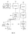
- Fig. 1a shows a device for calculating loudspeaker signals for a plurality of loudspeakers, which may for example be arranged at predetermined positions in a reproduction room, using a plurality of audio sources, wherein an audio source comprises an audio signal 10.
- the audio signals 10 are supplied to an out-transformation stage 100, which is designed to carry out a block-by-block transformation of each audio signal into a spectral range, so that a plurality of temporally consecutive short-time spectra are obtained for each audio signal.
- a memory 200 is provided, which is designed to store a number of temporally successive short-term spectra for each audio signal.
- each short-term spectrum of the plurality of short-term spectra may be assigned a time-increasing time value, and the memory then stores the temporally-consecutive short-term spectra for each audio signal in association with the time values.
- the short-term spectra in the memory do not have to be arranged in chronological succession here. Instead, the short-term spectra, for example, in a RAM memory at any point be stored as long as a memory contents table is present, which identifies which time value corresponds to which spectrum, and which spectrum belongs to which audio signal.
- the memory access controller is thus configured to access a specific short-term spectrum from the plurality of short-term spectra for a combination of loudspeaker and audio signal based on a delay value given for this audio-signal-loudspeaker combination.
- the determined short-term spectra determined by the memory access controller 600 are then applied to a filtering stage 300 for filtering the determined short-term spectra for combinations of audio signals and loudspeakers to perform filtering with a filter provided for the respective audio signal and loudspeaker combination for each Such combination of audio signal and speaker to obtain a sequence of filtered short-term spectra.
- the filtered short-term spectra are then supplied from the filter stage 300 to a summing stage 400 to sum the filtered short-term spectrum for a loudspeaker such that a summed short-term spectrum is obtained for each loudspeaker.
- the accumulated short-term spectra are then applied to a back-transformation stage 800 for block-wise back-transforming the summed short-term spectra for the loudspeakers to obtain the short-term spectra in a time range from which the loudspeaker signals can be determined.
- the loudspeaker signals are thus output from the back-transformation stage 800 at an output 12.
- the delay values 701 are provided by a Wave Field Synthesis Operator (WFS operator) 700 for each embodiment of the invention, in which the device is a wave field synthesis device, which is fed via an input 702 for each individual audio signal and loudspeaker combination and, depending on the loudspeaker positions, ie the positions in which the loudspeakers are arranged in the reproduction room, and which are supplied via an input 703, the delay values 701 are calculated. If the device is designed for a different application than for the wave field synthesis, so z. For example, for an Ambisonics implementation or the like, an element corresponding to the WFS operator 700 will also be present, which calculates delay values for individual loudspeaker signals or calculates delay values for individual audio signal loudspeaker combinations.
- WFS operator 700 Wave Field Synthesis Operator 700 for each embodiment of the invention, in which the device is a wave field synthesis device, which is fed via an input 702 for each individual audio signal and loudspeaker combination and, depending on the loudspeaker positions, ie the positions in
- the WFS operator 700 will calculate not only the delay values but also scaling values, which typically can also be considered in the filter stage 300 by a scaling factor. Thus, these can be achieved by scaling the filter coefficients used in filter stage 300 be taken into account without incurring additional calculation effort.
- the memory access controller 600 may therefore be configured in a particular implementation to obtain delay values for various audio signal and speaker combinations, and to calculate an access value to the memory for each combination, as further described with reference to FIG Fig. 1b is pictured. Accordingly, as also referring to Fig. 1b
- the filter stage 300 may be configured to obtain delay values for various combinations of audio signal and loudspeaker to calculate therefrom a number of zeros to be considered in the impulse responses for the individual audio signals / speaker combinations.
- the filter stage 300 is therefore configured to implement a finer granularity delay in multiples of the sample period while the memory access controller 600 is configured to provide, through efficient memory access, delays in the granularity of the feed B from the out-of-stage is applied to implement.
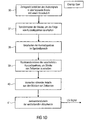
- FIG. 12 shows a sequence of functions performed by elements 700, 600, 300 of FIG Fig. 1a can be executed.
- the WFS operator 700 is configured to provide a delay value D as shown in step 20 in FIG Fig. 1b is shown.
- the memory access controller 600 will divide the delay value D into a multiple of the block size or the feed B and a remainder.
- the delay value D is equal to the product of the feed B and the multiple D b and the remainder.
- the multiple D b on the one hand and the remainder D r on the other hand can also be calculated by performing an integer division, namely one integral division of the time duration corresponding to the delay value D and the time duration corresponding to the feed B. The result of the integer division is then D b and the remainder of the integer division is D r .
- the memory access controller 600 performs a memory access control with the multiple D b in a step 22, as still referring to FIG Fig. 9 will be explained in more detail.
- the delay D b is thus efficiently implemented in the frequency domain because it is simply implemented by random access to a particular stored short-term spectrum selected according to the delay value or the multiple D b .
- the remainder D r is a multiple of the sample code T A and a remainder D r 'split.
- the sampling period T A still referring to FIG Fig.
- the sample period represents between two values of the impulse response typically associated with the sample period of the discrete audio signals at the input 10 of the out-of-step stage 100 of FIG Fig. 1 matches.
- the multiple D A of the sampling period T A is then used in a step 24 to control the filter by inserting D A zeroes into the impulse response of the filter.
- the remainder of the division in step 23, which is denoted by D r ', is then, if an even finer delay control than is already necessary by the quantization of the sampling periods T A , used in a step 25, where a fractional delay Filter (FD filter or a filter with a broken delay) according to D r 'is set.
- FD filter fractional delay Filter
- the delay achieved by controlling the filter in step 24 may be considered as a "time-domain" delay, although due to the particular implementation of the filter stage, this delay in the frequency domain is due to the particular short-term spectrum read from memory 200 using the multiple D b .
- the first block is the time that corresponds to the product of D b , which is the multiple of the block size with the block size.
- the second delay block is the multiple D A of the sampling period T A , that is to say a time duration which corresponds to this product D A x T A. This leaves a fractional delay delay or a delay residue D r 'left over. D r 'is smaller than T A , and D A x T A is less than B, which is directly due to the two division equations adjacent to blocks 21 and 23 in FIG Fig. 1b results.
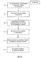
- Fig. 1c Referring to a preferred implementation of filter stage 300.
- an impulse response is provided for an audio signal speaker combination. Especially for directional sound sources you will have your own impulse response for every combination of audio signal and loudspeaker. However, for other sources as well, there are different impulse responses, at least for certain combinations of audio signal and loudspeaker.
- the number of zeros to be inserted that is, the value D A is determined, as determined by step 23 in FIG Fig. 1b has been shown.
- a step 32 a number of zeroes equal to D A are inserted in the impulse response at the beginning of the impulse response to obtain a modified impulse response. This is on Fig. 8a Referenced. Fig.
- step 33 a transformation of this modified impulse response, ie the impulse response according to Fig. 8b performed in the spectral range.
- step 34 preferably a spectrally value-wise multiplication of the determined short-term spectrum, ie the short-term spectrum, which has been read from the memory due to D b and thus determined, with the transformed modified impulse response obtained in step 33 is performed Finally, to obtain a filtered short-term spectrum.
- the out-of-step stage 100 is configured to determine the sequence of short-term spectra with the feed B from a sequence of temporal samples, such that a first sample of a first block of temporal samples converted to a short-term spectrum is spaced from a first sample of a second subsequent block of temporal samples by a number of samples equal to the feed value.
- the feed value is thus defined by the respective first sample value of the new block, this feed value, as it still is based on the Fig. 1d and 1e is present for both the overlap save method and the overlap add method.
- a time value associated with a short-term spectrum is stored as a block index indicating how many advancement values the first sample of the short-term spectrum is temporally distant from a reference value.
- the reference value is z.
- the index 0 of the short-term spectrum at 249 in Fig. 9 is a block index indicating how many advancement values the first sample of the short-term spectrum is temporally distant from a reference value.
- the memory access means is preferably configured to determine the determined short-term spectrum based on the delay value and the time value of the determined short-term spectrum such that the time value of the determined short-term spectrum equals the integer result of a division from the time duration corresponding to the delay value and the time duration. which corresponds to the feed value is or is greater by one.
- exactly the integer result used which is always smaller than the actually required delay.
- the integer result plus one could also be used, whereby these values are to a certain extent a "rounding up" of the actually required delay. In the case of a rounding up, a delay that is a bit too long is reached, but this can easily be enough for applications.
- the rest z. B. greater than or equal to 50% of the time corresponding to the feed, so can be rounded up, so be taken by one greater value.
- the remainder is less than 50%, it can be "rounded off", ie the exact result of the integer division can be taken. From a rounding can actually be spoken, if the rest not z. B. is also implemented by inserting zeros.
- the rounding implementation described above will be useful if delay is applied only with granulation of a block length, that is, if no finer delay is achieved by inserting zeroes in an impulse response. If, on the other hand, a finer delay is achieved by inserting zeroes into an impulse response, the block offset is rounded and not rounded up to determine the block offset.
- Fig. 9 shows a special memory 300 having an input interface 250 and an output interface 360.
- the audio signal 1 the audio signal 2, the audio signal 3 and the audio signal 4 is stored in the memory.
- a temporal sequence of short-term spectra with exemplary seven short-term spectra.
- the spectra are read into the memory so that there are always seven short-term spectra in the memory and then, when the memory is filled and another new short-term spectrum is introduced into the memory, the corresponding short-term spectrum "drops out" at the output 260 of the memory. This falling out is implemented by overwriting the memory cells, for example, or by resorting the indices to the individual memory fields accordingly, and is in Fig.
- the access control accesses via an access control line 265 in order to read out certain memory fields, that is to say certain short-term spectra, which are then sent via a readout output 267 to the filter stage 300 of FIG Fig. 1a to be delivered.
- a particular example access control could be used to implement Fig. 4 and there for specific OS blocks, as in Fig. 9 are shown, ie for certain audio signal speaker combinations corresponding short-term spectra of the audio signals at the corresponding time value, which is a multiple of B in Fig. 9 is at 269, read.
- the delay value could be such that a delay of two feed lengths 2B is required for the combination OS 301.
- no delay ie a delay of 0 through the delay value, could be required for the combination OS 304, while a delay of five feed values, ie 5B, is required for OS 302, as described in US Pat Fig. 9 is shown.
- the memory access controller 265 would be in accordance with the table 270 in FIG Fig. 9 and then provide the appropriate short-term spectra, via output 267, to the filter stage, as still referring to FIG Fig. 4 is set out.
- the storage depth is at the in Fig. 9
- seven short-term spectra are shown, so that a delay can be implemented that is at most equal to the time duration corresponding to six feed values B.
- the memory in Fig. 9 a value of D b of Fig. 1b , Step 21 of a maximum of 6 can be implemented.
- the memory may be larger or smaller or deeper or less deep.
- the filter stage is designed to determine a modified impulse response from an impulse response of a filter provided for the combination of loudspeaker and audio signal by inserting a number of zeros at the beginning of the impulse response, the number of zeros depends on the delay value for the combination of audio signal and loudspeaker and the selected specific short-term spectrum for the combination of audio signal and loudspeaker.
- the filter stage is adapted to insert a number of zeros such that a time duration equal to the number of zeros and equal to the value D A may be less than or equal to the remainder of the integer division from the residual value D r and Sampling time T A of Fig. 1b is. Still referring to Fig.
- the impulse response of the filter may be an impulse response for a fractional delay filter configured to achieve a delay according to a fraction of a time between adjacent discrete impulse response values, the fraction equal to the delay value (D - D b x B - D A x T A ) of Fig. 1b is, as it also from 26 in Fig. 1b is apparent.
- the memory 200 for each audio source comprises a frequency domain delay line or FDL 201, 202, 203 of FIG Fig. 4 where FDL stands for Frequency Delay Line.
- FDL stands for Frequency Delay Line.
- the FDL 201, 202, 203 which also in Fig. 9 shown schematically accordingly , allows random access to the short-term spectra stored for the corresponding source or audio signal, with access via a time value or index 269 executable for each short-term spectrum.
- the Hin transformation stage is formed with a number of transformation blocks 101, 102, 103 equal to the number of audio signals.
- the re-transformation stage 800 is formed with a number of transformation blocks 101, 102, 103 equal to the number of speakers.
- a frequency-domain delay line 201, 202, 203 is provided for each audio source for each audio signal, and further the filter stage is designed such that it contains a number of individual filters 301, 302, 303, 304, 305, 306, 307, 308, 309, wherein the number of individual filters is equal to the product of the number of audio sources and the number of speakers. In other words, this means that for each audio signal-speaker combination, a separate individual filter is included for simplicity Fig. 4 labeled OS is present.
- the down-transformation stage 100 and the back-transformation stage 800 are formed according to an overlap-save method, which will be described below with reference to FIG Fig. 1d is explained.
- the overlap save method is a fast folding method.
- the in Fig. 1e is explained, the input sequence is decomposed into overlapping subsequences, as at 36 in FIG Fig. 1d is shown. From the formed periodic folding products (cyclic folding) then those parts are taken that match the aperiodic, fast folding.
- the overlap save method can also be used to efficiently implement higher order FIR filters.
- the blocks formed in step 36 are then processed in the out-of-step stage 100 of FIG Fig.
- the output signal which results from the convolution of two finite signals, can generally be divided into three parts, the transient response, the stationary behavior and the decay behavior.
- the input signal is split into segments and each segment is individually folded by cyclic convolution with a filter.
- both the out-of-step stage 100 and the back-to-back stage 800 may be configured to perform an overlap-add method.
- the overlap-add technique also referred to as segmented convolution, is also a fast convolution method and is controlled such that an input sequence is split into actually contiguous blocks of samples at a feed B, as shown at 43 , However, these blocks become consecutive overlapping blocks due to the addition of zeros (also referred to as zero-padding) for each block, as shown at 44.
- the input signal is thus divided into sections of length B, which are then lengthened by zero-padding according to step 44 to bring the result of the convolution operation to a greater length.
- step 44 the zero-padded blocks produced by step 44 are transformed in a step 45 by the out-of-step stage 100 to obtain the sequence of short-term spectra.
- processing of the short-term spectra in the spectral range is performed in a step 46, to then perform a back transformation of the processed spectra in a step 47 to obtain blocks of time values.
- step 48 an overlapping addition of the blocks of time values takes place to obtain a correct result.
- the results of the individual convolutions are therefore added up where the individual convolution products overlap, and the result of the operation corresponds to the convolution of a theoretically infinitely long input sequence.
- an overlapping addition of the blocks of time values is performed.
- the out-transformation stage 100 and the back-transformation stage 800 are considered as individual FFT blocks, as in FIG Fig. 4 or IFFT blocks as in Fig. 4 also shown trained.
- a DFT algorithm that is to say a discrete Fourier transformation algorithm, which may also deviate from the FFT algorithm is preferred.
- other frequency domain transformation techniques such as discrete sine transform (DST) techniques, may also be used.
- DCT Discrete cosine transformation
- MDCT modified discrete cosine transformation
- the apparatus of the present invention is preferably used for a wave-field synthesis system such that there is a wave-field synthesis operator 700 that is configured to listen to any combination of speaker or audio source using a virtual position of the audio source and position of the loudspeaker to calculate the delay value, on the basis of which the memory access controller 600 and the filter stage 300 can then operate.
- Fig. 7 shows the geometry of the labels used in the general equations of wave field synthesis, ie in the wave field synthesis operator.
- the WFS operator is frequency-dependent, thus having a dedicated amplitude and phase corresponding to a frequency-dependent delay for each frequency.
- this frequency dependent operation requires filtering of the time domain signal.
- This filtering operation can be implemented as FIR filtering, where the FIR coefficients are determined by suitable design methods from the frequency-dependent WFS operator.
- the FIR filter also contains a delay, the main part of the delay (delay) being determined by the signal propagation time between the virtual source and the loudspeaker and thus being frequency-independent, ie constant.
- this frequency-dependent delay is achieved by the in conjunction with the Fig. 1a-1e described procedures edited.
- the present invention may also be applied to alternative implementations where the sources are non-directional, or where there are only frequency independent delays, or where fast convolution is generally to be employed along with a delay between certain audio signal speaker combinations.
- the sound field of the primary source is generated in the region y ⁇ y L by using a linear distribution of secondary monopole sources along x (black dots).
- the speed must be V n ⁇ r ⁇ ⁇ the primary source ⁇ be known at the positions of the secondary sources according to their normals n ,
- ⁇ is the angular frequency
- c is the speed of sound
- H 0 2 ⁇ ⁇ c ⁇ r ⁇ R - r ⁇ is the second order Hankel function of order 0.
- the path from the primary source position to the secondary source position is designated by r.
- r R is the path from the secondary source to the receiver R.
- G ( ⁇ , ⁇ ) 1.
- monopole sources In addition to the synthesis of monopole sources, a common WFS system makes it possible to render planar wavefronts, called plane waves. These may be considered monopole sources arranged at an infinite distance. As in the case of monopole sources, the resulting synthetic operator consists of a static filter, a gain factor, and a time delay.
- the gain factor A depends on the directional characteristic, the orientation and the frequency of the virtual source as well as on the positions of the virtual and secondary sources.
- time-discrete filters for the directional characteristics of the frequency response (8) must be determined. Due to their ability to approximate arbitrary frequency responses and their inherent stability, only FIR filters are considered here.
- K is the order of magnitude of the directivity filter. Since such filters are required for any combination of N virtual sources and M loudspeakers, the generation must be relatively efficient.
- a simple window (or frequency scan design) is used here.
- the desired frequency response (9) is evaluated at K + 1 equidistantly sampled frequency values in the interval 0 ⁇ ⁇ ⁇ 2 ⁇ .
- IFT inverse discrete Fourier transform
- this design method allows for several optimizations.
- the directivity filters h m, n [ k ] introduce synthesis errors in two ways. On the one hand, the limited filter order leads to an imperfect approximation of A D ( r R , r , ⁇ , ⁇ ). On the other hand, the infinite summation of (4) must be replaced by a finite limit. As a result, the beam width of the generated directivity characteristics can not become infinitely narrow.
- Fig. 2 shows the basic structure of signal processing when using a simple WFS operator based on a scale & delay operation. Shown is the signal processing structure of WFS processing systems for the synthesis of basic primary source types.
- WFS rendering is commonly implemented as a discrete-time processing system. It consists of two general tasks: computation of the synthesis operator and application of this operator to the time-discrete source signals. The latter is referred to below as WFS processing.
- the effect of the synthetic operator on overall complexity is typically low because it is relatively rarely calculated. If the source properties change only discretely, the operator is calculated as needed. For continuously changing source properties, e.g. in the case of moving sound sources, it is typically sufficient to compute these values on a coarse grid and use simple interpolation techniques in between.
- FIG. 2 shows the structure of a typical WFS rendering system with N virtual sources and M speakers.
- S & D scale-and-delay operation
- the delay value is rounded down to the nearest integer multiple of the sample period and applied to the delay line as an indexed access.
- more complex algorithms are required to interpolate the source signal at arbitrary positions between samples.
- the number of scaling and delaying operations is formed by the product of the number of virtual sources N and the number of loudspeakers M. Thus, this product typically reaches high values. Consequently, the scaling and delaying operation is the most power-critical part of most WFS systems, even if only integer delays are used.
- Fig. 3 shows the basic structure of the signal processing when using the overlap & save technique.
- the overlap save method is a fast folding method.
- the input sequence x [n] is decomposed into overlapping subsequences. From the formed periodic folding products (cyclic folding) then those parts are taken that match the aperiodic, fast folding.
- the invention proposes a signal processing scheme based on two interacting effects.
- the first effect concerns the fact that the efficiency of FIR filters can often be increased by using fast convolution techniques in the transform domain , such as overlap-save or overlap-add.
- these algorithms transform segments of the input signal into the frequency domain by fast Fourier transform (FFT) techniques, perform convolution due to frequency domain multiplication, and transform the signal back into the time domain.
- FFT fast Fourier transform
- the filter order where transform based filtering becomes more efficient than direct convolution is typically between 16 and 50.
- the forward and inverse FFT operations form the Much of the computational effort.
- Another embodiment for reducing computational effort utilizes the structure of the WFS processing scheme.
- every input signal for a large Number of delay and filter operations used is used.
- the results are summed for a large number of sound sources for each speaker.
- partitioning the signal processing algorithm which performs common operations only once for each input or output signal, promises great efficiencies.
- such partitioning of the WFS rendering algorithm provides significant performance improvements for moving sound sources from basic source types.
- FFT fast Fourier transforms
- the frequency domain representation is used several times to convolute the individual loudspeaker signal components by an overlap save operation, ie a complex multiplication.
- the loudspeaker signals are calculated in the frequency domain by accumulating the component signals of all sources.
- IFFT fast inverse Fourier transform
- Fig. 4 shows the basic structure of the signal processing in the use of a frequency domain delay line according to the invention. Shown is a block-based transform domain WFS signal processing scheme. OS stands for overlap-save and FDL stands for Frequency-Domain Delay Line.
- Fig. 4 shows a specific implementation of the embodiment of Fig. 1a which has a matrix-shaped structure, wherein the out-of-step stage 100 comprises individual FFT blocks 101, 102, 103.
- the memory 200 includes various frequency-domain delay lines 201, 202, 203, which may be accessed via the memory access controller 600 shown in FIG Fig. 4 is not shown, to determine for each filter stage 301-309 the correct short-term spectrum and the corresponding filter stage at a given time, as shown by Fig. 9 has been set out.
- the summer 400 includes schematically summed summers 401-406, and the re-transform stage 800 includes individual ones IFFT blocks 801, 802, 803 to finally receive the loudspeaker signals.
- both the blocks 101-103 and 801-803 are designed to perform the correspondingly necessary processing steps before the actual transformation or after the actual back transformation, which are required by fast folding methods, such as the overlap-save method or the overlap-add method.
- the WFS operator determines a single delay for each source-speaker combination.
- the proposed signal processing scheme allows efficient multi-channel convolution, the application of these delays requires detailed consideration.
- integer-value sample delays can be implemented by accessing a time domain delay line with little effect on overall complexity.
- a time delay can not be implemented in the same way.
- any time delay can be readily incorporated into the FIR directivity filter.
- this approach results in very large filter lengths and hence large FFT block sizes.
- this significantly increases the computational effort and the storage requirements.
- the latency to form input blocks is unacceptable for many applications due to the blocking delay required for such large FFT sizes.
- the input signal is segmented into overlapping blocks of size L and a feed (or delay block size) of B between adjacent blocks.
- the blocks are transformed into the frequency domain and are denoted by X n [ l ], where n denotes the source and l is the block index.
- These blocks are stored in a structure that allows indexed access of the form X n [li ] to the most recent frequency domain blocks.
- This data structure is conceptually identical to Frequency Domain Delay Lines used in the context of partitioned convolution.
- the delay value D is partitioned into a multiple of the block delay magnitude and a remainder D r and D r ', respectively.
- D D b ⁇ B + D r With 0 ⁇ D r ⁇ B - 1 .
- D b ⁇ N D b ⁇ N ,
- the block delay D b is applied as an indexed access in the frequency domain delay line.
- this operation corresponds to prefixing h m, n [ k ] with D r zeros.
- the resulting filter is padded with zeroes according to the requirements of the overlap save operation.
- the frequency domain filter representation H m . n d obtained by an FFT.
- the remainder of the algorithm is identical to the usual overlap-save algorithm.
- the blocks Y m [ l ] are transformed into the time domain, and the speaker drive signals y m [k] are formed by deleting a predetermined number of samples from each time domain block.
- This signal processing structure is in Fig. 4 shown schematically.
- the proposed processing scheme can be extended to arbitrary delay values by including a FD (Fractional Delay) filter, a so-called directivity filter H m . n d k .
- FD Fractional Delay
- H m . n d k Only FIR FD filters are considered here, as they can be easily integrated into the proposed algorithm.
- the residual delay D r is partitioned into an integer part D int and a fractional delay value d, as is usual in the FD filter design.
- the integer part is integrated in H m . n d k by prefixing D int zeros to h m, n [ k ].
- the fractional delay value is applied H m .
- Fig. 5 shows the basic structure of the signal processing with a frequency domain delay line according to the invention.
- the source signal x k is transformed into overlapping FFT calculation blocks 502 of the block length L into the spectra, the FFT calculation blocks having an overlap of length (LB) and a length B feed.
- the fast convolution after the overlap-save method (OS) and the backward transformation with an IFFT into the loudspeaker signals y 0 ... Y M-1 are performed at the step 503.
- the decisive factor here is the way in which access to the spectra takes place. Exemplary accesses 504, 505, 506 and 507 are shown in the figure. Based at the time of access 507, the accesses 504, 505 and 506 are in the past.
- the speaker 511 when the speaker 511 is accessed with the access 507 and the speakers 510, 512 are simultaneously driven with the access 506, it appears to the listener as if the speaker signals of the speakers 510, 512 are delayed from the speaker signal of the speaker 511 , The same applies to the access 505 and the loudspeaker signals of the loudspeakers 509, 513 as well as to the access 504 and the loudspeaker signals of the loudspeakers 508, 514.
- each individual speaker can be controlled with a delay which corresponds to a multiple of the block feed B. If a further delay is to be provided which is less than the block feed B, then this can be achieved by prefixing the respective impulse response of the filter which is the subject of the overlap-save operation.
- the main parameters that determine the complexity of a directional sound source processing algorithm are the number of virtual sources N, the number of loudspeakers M , and the filtering order of the directional filter K.
- the Displacement between adjacent input blocks also referred to as block delay B
- performance and memory requirements are also referred to as block delay B
- the blockwise operation of the fast convolution algorithms introduces an implementation latency of B-1 samples.
- the maximum allowable delay value, referred to as D max given as a number of samples, affects the amount of memory required for the delay line structures.
- linear convolution performs NM time domain convolutions of order K. This amounts to NM ( 2K + 1) commands per sample.
- M (N -1 ) real additions are needed to accumulate the speaker drive signals.
- the memory required for a single delay line is D max + K floating point values.
- Each of the MN FIR filters h m, n [ k ] requires K + 1 floating-point memory words.
- the second algorithm calculates the MN FIR filters separately using the overlap-save fast convolution method.
- a real-valued FFT of size L and an inverse FFT of the same size are performed.
- a command count of pLlog 2 (L) is assumed for a forward or inverse FFT of size L, where p is a proportionality constant that depends on the actual implementation. For p, a value between 2.5 and 3 can be assumed.
- the complex vector multiplication of length L performed in the overlap-save method requires about L / 2 complex multiplications. Since a single complex multiplication is implemented by 6 arithmetic instructions, the overhead for vector multiplication is 3L instructions.
- filtering requires the use of the overlap-save method M N K + B B ⁇ 2 ⁇ p log 2 K + B + 3 for a single output sample on all speaker signals.
- the overhead of accumulating the loudspeaker signals M ( N- 1) amounts to commands.
- the delay line memory is identical to the linear convolution algorithm.
- a single FFT or inverse FFT operation requires p (K + 2B-1) log 2 (K + 2B-1) instructions.
- N forward and M inverse FFT operations are required for each audio block.
- the complex multiplication and addition are both performed on the frequency domain representation and require 3 (K + 2B-1) and K + 2B-1 instructions, respectively, for each symmetric frequency domain block of length K + 2B-1.
- Fig. 6a As shown, the efficiency of the filter-wise fast convolution algorithm exceeds that of the linear convolution algorithm by an almost constant factor.
- the linear convolution algorithms require about 2 , 9 10 6 memory words.
- the fast filter-by-convolution algorithm uses about 5.0 ⁇ 10 6 floating point memory locations.
- the increase is due to the size of the precalculated frequency domain filter representations.
- the proposed algorithm requires about 8.6 x 10 6 words of memory due to the frequency domain delay line and the increased block size for the frequency domain representations of the input signal and the filters.
- the performance improvement of the proposed algorithm as compared to filter-wise fast convolution is gained by an increase in required memory of about 72.7%.
- the proposed algorithm may be considered as a space-time tradeoff that uses additional memory to store pre-computed results, such as frequency domain representations of the input signal, to allow for more efficient implementation.
- the additional memory requirements can have a detrimental effect on performance, such as reduced cache locality.
- the reduced number of instructions that imply a reduced number of memory accesses will minimize this effect. It is therefore necessary to examine and evaluate the performance gains of the proposed algorithm for the intended hardware architecture.
- the parameters of the algorithm such as the FFT block size L or the block delay B, must be matched to the specific target platform.
- the method according to the invention can be implemented in hardware or in software.
- the implementation may be on a non-transitory storage medium, a digital storage medium, in particular a floppy disk or CD with electronically readable control signals, which may be used with a programmable computer system that the process is performed.
- the invention thus also consists in a computer program product with a program code stored on a machine-readable carrier for carrying out the method when the computer program product runs on a computer.
- the invention can thus be realized as a computer program with a program code for carrying out the method when the computer program runs on a computer.
Description
Die vorliegende Erfindung betrifft eine Vorrichtung und ein Verfahren zum Berechnen von Lautsprechersignalen für eine Mehrzahl von Lautsprechern unter Verwendung einer Filterung im Frequenzbereich, wie beispielsweise eine Wellenfeldsynthese-Renderer-Vorrichtung sowie ein Verfahren zum Betreiben einer derartigen Vorrichtung.The present invention relates to an apparatus and a method for calculating loudspeaker signals for a plurality of loudspeakers using frequency-domain filtering, such as a wave-field synthesis renderer device and a method of operating such a device.
Im Bereich der Unterhaltungselektronik besteht ein ständiger Bedarf an neuen Technologien und innovativen Produkten. Ein Beispiel ist hier die möglichst realitätsnahe Wiedergabe von Audiosignalen.In the field of consumer electronics, there is a constant need for new technologies and innovative products. An example here is the most realistic reproduction of audio signals.
Verfahren zur mehrkanaligen Lautsprecherwiedergabe von Audiosignalen sind seit vielen Jahren bekannt und standardisiert (siehe, z.b.,
Ein besserer natürlicher Raumeindruck sowie eine stärkere Einhüllung bei der Audiowiedergabe kann mit Hilfe einer neuen Technologie erreicht werden. Die Grundlagen dieser Technologie, die so genannte Wellenfeldsynthese (WFS; WFS = Wave-Field Synthesis), wurden an der TU Delft erforscht und erstmals in den späten 80er-Jahren vorgestellt (Berkhout, A.J.; de Vries, D.; Vogel, P.: Acoustic Control By Wavefield Synthesis. JASA 93, 1993).A better natural spatial impression as well as a stronger envelope in the audio reproduction can be achieved with the help of a new technology. The basics of this technology, Wave Field Synthesis (WFS), were researched at the TU Delft and first introduced in the late 1980s (Berkhout, AJ, de Vries, D .; Vogel, P.). : Acoustic Control By Wavefield Synthesis JASA 93, 1993).
Infolge der enormen Anforderungen dieser Methode an Rechnerleistung und Übertragungsraten wurde die Wellenfeldsynthese bis jetzt nur selten in der Praxis angewendet. Erst die Fortschritte in den Bereichen der Mikroprozessortechnik und der Audiocodierung gestatten inzwischen den Einsatz dieser Technologie in konkreten Anwendungen.Due to the enormous demands of this method on computer performance and transmission rates, wave field synthesis has rarely been used in practice. Only the advances in the areas of microprocessor technology and audio coding allow the use of this technology in concrete applications.
Die Grundidee von WFS basiert auf der Anwendung des Huygens'schen Prinzips der Wellentheorie: Jeder Punkt, der von einer Welle erfasst wird, ist Ausgangspunkt einer Elementarwelle, die sich kugelförmig bzw. kreisförmig ausbreitet.The basic idea of WFS is based on the application of Huygens' principle of wave theory: every point, which is detected by a wave, is the starting point of an elementary wave, which spreads in a spherical or circular manner.
Angewandt auf die Akustik kann durch eine große Anzahl von Lautsprechern, die nebeneinander angeordnet sind (einem so genannten Lautsprecherarray), ein beliebiges Schallfeld nachgebildet werden. Dazu wird das Audiosignal eines jeden Lautsprechers durch die Anwendung eines sog. WFS-Operators aus dem Audiosignal der Quelle erzeugt. Im einfachsten Falle, z.B. bei der Wiedergabe einer Punktquelle und einem linearen Lautsprecherarray, entspricht der WFS-Operator einer Amplitudenskalierung und einer Zeitverzögerung des Eingangssignals. Die Anwendung dieser Amplitudenskalierung und Zeitverzögerung wird im folgenden als Scale&Delay bezeichnet.Applied to the acoustics can be simulated by a large number of speakers, which are arranged side by side (a so-called speaker array), any sound field. For this purpose, the audio signal of each speaker is generated by the application of a so-called. WFS operator from the audio signal of the source. In the simplest case, e.g. when playing a point source and a linear loudspeaker array, the WFS operator corresponds to an amplitude scaling and a time delay of the input signal. The application of this amplitude scaling and time delay is hereafter referred to as Scale & Delay.
Im dem Fall einer einzelnen wiederzugebenden Punktquelle und einer linearen Anordnung der Lautsprecher, können eine Zeitverzögerung und eine Amplitudenskalierung auf das Audiosignal jedes Lautsprechers angewandt werden, dass sich die abgestrahlten Klangfelder der einzelnen Lautsprecher richtig überlagern. Bei mehreren Schallquellen wird für jede Quelle der Beitrag zu jedem Lautsprecher getrennt berechnet und die resultierenden Signale addiert. Befinden sich die wiederzugebenden Quellen in einem Raum mit reflektierenden Wänden, dann müssen auch Reflexionen als zusätzliche Quellen über das Lautsprecherarray wiedergegeben werden. Der Aufwand bei der Berechnung hängt daher stark von der Anzahl der Schallquellen, den Reflexionseigenschaften des Aufnahmeraums und der Anzahl der Lautsprecher ab.In the case of a single point source to be reproduced and a linear arrangement of the speakers, a time delay and amplitude scaling can be applied to the audio signal of each loudspeaker so that the radiated sound fields of the individual loudspeakers are properly superimposed. With multiple sound sources, the contribution to each speaker is calculated separately for each source and the resulting signals added together. If the sources to be reproduced are in a room with reflective walls, reflections must also be reproduced as additional sources via the loudspeaker array. The cost of the calculation therefore depends heavily on the number of sound sources, the reflection characteristics of the recording room and the number of speakers.
Der Vorteil dieser Technik liegt im Besonderen darin, dass ein natürlicher räumlicher Klangeindruck über einen großen Bereich des Wiedergaberaums möglich ist. Im Gegensatz zu den bekannten Techniken werden Richtung und Entfernung von Schallquellen sehr exakt wiedergegeben. In beschränktem Maße können virtuelle Schallquellen sogar zwischen dem realen Lautsprecherarray und dem Hörer positioniert werden.The advantage of this technique is in particular that a natural spatial sound impression over a large area of the playback room is possible. In contrast to the known techniques, the direction and distance of sound sources are reproduced very accurately. To a limited extent, virtual sound sources can even be positioned between the real speaker array and the listener.
Die Anwendung der Wellenfeldsynthese liefert gute , wenn die in der Theorie angenommenen Vorraussetzungen, wie ideale Lautsprechercharakteristik, regelmäßige, lückenlose Lautsprecherarrays oder Freifeldbedingungen für die Schallausbreitung zumindest näherungsweise erfüllt sind. In der Praxis werden diese Bedingungen jedoch häufig verletzt, z. B. durch unvollständige Lautsprecherarrays oder einen signifikanten Einfluss der Raumakustik.The application of wave field synthesis provides good, if the assumed assumptions in theory, such as ideal speaker characteristics, regular, gapless speaker arrays or free field conditions for sound propagation are at least approximately fulfilled. In practice, however, these conditions are often violated, for. B. by incomplete speaker arrays or a significant influence of room acoustics.
Eine Umgebungsbeschaffenheit kann durch die Impulsantwort der Umgebung beschrieben werden.An environmental condition can be described by the impulse response of the environment.
Dies wird anhand des nachfolgenden Beispiels näher dargelegt. Es wird davon ausgegangen, dass ein Lautsprecher ein Schallsignal gegen eine Wand aussendet, deren Reflexion unerwünscht ist.This will be explained in more detail with reference to the following example. It is assumed that a loudspeaker emits a sound signal against a wall whose reflection is undesirable.
Für dieses einfache Beispiel würde die Raumkompensation unter Verwendung der Wellenfeldsynthese darin bestehen, dass zunächst die Reflexion dieser Wand bestimmt wird, um zu ermitteln, wann ein Schallsignal, das von der Wand reflektiert worden ist, wieder beim Lautsprecher ankommt, und welche Amplitude dieses reflektierte Schallsignal hat. Wenn die Reflexion von dieser Wand unerwünscht ist, so besteht mit der Wellenfeldsynthese die Möglichkeit, die Reflexion von dieser Wand zu eliminieren, indem dem Lautsprecher ein zu dem Reflexionssignal gegenphasiges Signal mit entsprechender Amplitude zusätzlich zum ursprünglichen Audiosignal eingeprägt wird, so dass die hinlaufende Kompensationswelle die Reflexionswelle auslöscht, derart, dass die Reflexion von dieser Wand in der Umgebung, die betrachtet wird, eliminiert ist. Dies kann dadurch geschehen, dass zunächst die Impulsantwort der Umgebung berechnet wird und auf der Basis der Impulsantwort dieser Umgebung die Beschaffenheit und Position der Wand bestimmt wird. Dabei wird der von der Wand zurückgeworfene Schall durch eine zusätzliche WFS-Schallquelle, eine sogenannte Spiegelschallquelle, dargestellt, deren Signal durch Filterung und Verzögerung aus dem ursprünglichen Quellsignal generiert wird.For this simple example, the space compensation using wavefield synthesis would be to first determine the reflection of that wall to determine when a sound signal reflected from the wall will return to the loudspeaker and what amplitude this reflected sound signal will be Has. If the reflection from this wall is undesirable, then with the wave field synthesis it is possible to eliminate the reflection from this wall by impressing the loudspeaker with a signal of opposite amplitude to the reflection signal in addition to the original audio signal, so that the traveling compensating wave is the Reflectance wave extinguished, so that the reflection from this wall in the environment that is considered, is eliminated. This can be done by first computing the impulse response of the environment and determining the nature and position of the wall based on the impulse response of that environment. In this case, the sound reflected by the wall is represented by an additional WFS sound source, a so-called mirror sound source, whose signal is generated by filtering and delay from the original source signal.
Wird zunächst die Impulsantwort dieser Umgebung gemessen und wird dann das Kompensationssignal berechnet, das dem Audiosignal überlagert dem Lautsprecher eingeprägt werden muss, so wird eine Aufhebung der Reflexion von dieser Wand stattfinden, derart, dass ein Hörer in dieser Umgebung den Eindruck hat, dass diese Wand überhaupt nicht existiert.If the impulse response of this environment is first measured and the compensation signal is then calculated, which must be impressed on the audio signal superimposed on the loudspeaker, a cancellation of the reflection from this wall will take place, such that a listener in this environment has the impression that this wall does not exist at all.
Entscheidend für eine optimale Kompensation der reflektierten Welle ist jedoch, dass die Impulsantwort des Raums genau bestimmt wird, damit keine Über- oder Unterkompensation auftritt.Decisive for an optimal compensation of the reflected wave, however, is that the impulse response of the room is accurately determined, so that no overcompensation or undercompensation occurs.
Die Wellenfeldsynthese ermöglicht somit eine korrekte Abbildung von virtuellen Schallquellen über einen großen Wiedergabebereich. Gleichzeitig bietet sie dem Tonmeister und Toningenieur neues technisches und kreatives Potential bei der Erstellung auch komplexer Klanglandschaften. Die Wellenfeldsynthese, wie sie Ende der 80-er Jahre an der TU Delft entwickelt wurde, stellt einen holographischen Ansatz der Schallwiedergabe dar. Als Grundlage hierfür dient das Kirchhoff-Helmholtz-Integral. Dieses besagt, dass beliebige Schallfelder innerhalb eines geschlossenen Volumens mittels einer Verteilung von Monopol- und Dipolschallquellen (Lautsprecherarrays) auf der Oberfläche dieses Volumens erzeugt werden können.The wave field synthesis thus allows a correct mapping of virtual sound sources over a large playback area. At the same time it offers the sound engineer and sound engineer new technical and creative potential in the creation of even complex soundscapes. Wave field synthesis, as developed at the TU Delft in the late 1980s, represents a holographic approach to sound reproduction. The basis for this is the Kirchhoff-Helmholtz integral. This states that any sound fields within a closed volume are distributed by means of a distribution of monopoly and dipole sound sources (speaker arrays) can be created on the surface of this volume.
Bei der Wellenfeldsynthese wird aus einem Audiosignal, das eine virtuelle Quelle an einer virtuellen Position aussendet, ein Synthesesignal für jeden Lautsprecher des Lautsprecherarrays berechnet, wobei die Synthesesignale derart hinsichtlich Amplitude und Verzögerung gestaltet sind, dass eine Welle, die sich aus der Überlagerung der einzelnen durch die im Lautsprecherarray vorhandenen Lautsprecher ausgegebenen Schallwelle ergibt, der Welle entspricht, die von der virtuellen Quelle an der virtuellen Position herrühren würde, wenn diese virtuelle Quelle an der virtuellen Position eine reale Quelle mit einer realen Position wäre.In wave field synthesis, from an audio signal that emits a virtual source at a virtual position, a synthesis signal is calculated for each loudspeaker of the loudspeaker array, the synthesis signals being designed in amplitude and delay such that a wave resulting from the superimposition of the individual the sound wave present in the loudspeaker array will correspond to the wave that would result from the virtual source at the virtual position if that virtual source at the virtual position were a real source with a real position.
Typischerweise sind mehrere virtuelle Quellen an verschiedenen virtuellen Positionen vorhanden. Die Berechnung der Synthesesignale wird für jede virtuelle Quelle an jeder virtuellen Position durchgeführt, so dass typischerweise eine virtuelle Quelle in Synthesesignalen für mehrere Lautsprecher resultiert. Von einem Lautsprecher aus betrachtet empfängt dieser Lautsprecher somit mehrere Synthesesignale, die auf verschiedene virtuelle Quellen zurückgehen. Eine Überlagerung dieser Quellen, die aufgrund des linearen Superpositionsprinzips möglich ist, ergibt dann das von dem Lautsprecher tatsächlich ausgesendete Wiedergabesignal.Typically, multiple virtual sources exist at different virtual locations. The computation of the synthesis signals is performed for each virtual source at each virtual location, typically resulting in one virtual source in multiple speaker synthesis signals. Seen from a loudspeaker, this loudspeaker thus receives several synthesis signals, which go back to different virtual sources. A superimposition of these sources, which is possible due to the linear superposition principle, then gives the reproduced signal actually emitted by the speaker.
Die Möglichkeiten der Wellenfeldsynthese können umso besser ausgeschöpft werden, je größer die Lautsprecherarrays sind, d. h. umso mehr einzelne Lautsprecher bereitgestellt werden. Damit steigt jedoch auch die Rechenleistung, die eine Wellenfeldsyntheseeinheit vollbringen muss, da typischerweise auch Kanalinformationen berücksichtigt werden müssen. Dies bedeutet im Einzelnen, dass von jeder virtuellen Quelle zu jedem Lautsprecher prinzipiell ein eigener Übertragungskanal vorhanden ist, und dass prinzipiell der Fall vorhanden sein kann, dass jede virtuelle Quelle zu einem Synthesesignal für jeden Lautsprecher führt, bzw. dass jeder Lautsprecher eine Anzahl von Synthesesignalen erhält, die gleich der Anzahl von virtuellen Quellen ist.The possibilities of wave field synthesis can be better exploited the larger the speaker arrays are, ie. H. the more individual speakers are provided. However, this also increases the computing power which a wave field synthesis unit has to accomplish, since channel information also typically has to be taken into account. This means in more detail that from each virtual source to each speaker in principle a separate transmission channel is present, and that in principle there may be the case that each virtual source leads to a synthesis signal for each speaker, or that each speaker a number of synthesis signals which equals the number of virtual sources.
Wenn insbesondere bei Kinoanwendungen die Möglichkeiten der Wellenfeldsynthese dahingehend ausgeschöpft werden sollen, dass die virtuellen Quellen auch beweglich sein können, so ist zu erkennen, dass aufgrund der Berechnung der Synthesesignale, der Berechnung der Kanalinformationen und der Erzeugung der Wiedergabesignale durch Kombination der Kanalinformationen und der Synthesesignale ganz erhebliche Rechenleistungen zu bewältigen sind.If, in particular, in cinema applications the possibilities of wave field synthesis are to be exploited to the extent that the virtual sources can also be mobile, then it can be seen that due to the calculation of the synthesis signals, the calculation of the channel information and the generation of the reproduction signals by combining the channel information and the synthesis signals quite considerable computing power has to be mastered.
Eine weitere wichtige Erweiterung der Wellenfeldsynthese ist die Wiedergabe von virtuellen Schallquellen mit komplexen, frequenzabhängigen Richtcharakteristiken. Für jede Quell-/Lautsprecherkombination muss hier neben einer Verzögerung auch die Faltung des Eingangssignals mit einem speziellen Filter berücksichtigt werden, was dann den Berechnungsaufwand bei bestehenden Systemen in der Regel übersteigt.Another important extension of wave field synthesis is the reproduction of virtual sound sources with complex, frequency-dependent directional characteristics. For each source / loudspeaker combination, in addition to a delay, the convolution of the input signal with a special filter must also be taken into account here, which then generally exceeds the computation effort in existing systems.
Die Aufgabe der vorliegenden Erfindung besteht darin, ein effizientes Konzept zum Berechnen von Lautsprechersignalen für eine Mehrzahl von Lautsprechern unter Verwendung von Audioquellen zu schaffen.The object of the present invention is to provide an efficient concept for calculating loudspeaker signals for a plurality of loudspeakers using audio sources.
Diese Aufgabe wird durch eine Vorrichtung zur Berechnung von Lautsprechersignalen gemäß Patentanspruch 1, ein Verfahren zum Berechnen von Lautsprechersignalen gemäß Patentanspruch 18 oder ein Computer-Programm gemäß Patentanspruch 19 gelöst.This object is achieved by a loudspeaker signal calculation apparatus according to
Die vorliegende Erfindung ist dahin gehend vorteilhaft, dass sie durch die Kombination einer Hin-Transformations-Stufe, einem Speicher, einer Speicherzugriffssteuerung, einer Filterstufe, einer Summiererstufe und einer Rück-Transformations-Stufe ein effizientes Konzept schafft, das sich dadurch auszeichnet, dass die Anzahl der Hin- und Rück-Transformationsberechnungen nicht für jede einzelne Kombination aus Audioquelle und Lautsprecher durchgeführt werden muss, sondern nur für jede einzelne Audioquelle.The present invention is advantageous in that it provides an efficient concept through the combination of an out-of-order stage, a memory, a memory access controller, a filter stage, a summer stage, and a re-transform stage, characterized in that the The number of round-trip transformation calculations need not be made for each individual audio source / speaker combination, but only for each individual audio source.
Gleichermaßen muss die Rück-Transformation nicht für jede einzelne Audiosignal-Lautsprecher-Kombination berechnet werden, sondern lediglich für die Anzahl der Lautsprecher. Dies bedeutet, dass die Anzahl der Hin-Transformationsberechnungen gleich der Anzahl der Audioquellen ist und die Anzahl der Rück-Transformationsberechnungen gleich der Anzahl der Lautsprechersignale bzw. der anzusteuernden Lautsprecher ist, wenn ein Lautsprechersignal einen Lautsprecher ansteuert. Besonders vorteilhaft ist ferner, dass die Einführung der Verzögerung im Frequenzbereich durch eine Speicherzugriffssteuerung auf effiziente Art und Weise erreicht wird, indem basierend auf einem Verzögerungswert für eine Audiosignal-Lautsprecher-Kombination der bei der Transformation verwendete Vorschub dazu vorteilhaft ausgenutzt wird. Insbesondere liefert die Hin-Transformations-Stufe für jedes Audiosignal eine Folge von Kurzzeitspektren, die für jedes Audiosignal in dem Speicher gespeichert werden. Die Speicherzugriffssteuerung hat somit Zugriff auf eine Folge von zeitlich aufeinanderfolgenden Kurzzeitspektren. Basierend auf dem Verzögerungswert wird dann für eine Audiosignal-Lautsprecher-Kombination das Kurzzeitspektrum aus der Folge von Kurzzeitspektren ausgewählt, das mit dem von beispielsweise einem Wellenfeldsynthese-Operator gelieferten Verzögerungswert am besten übereinstimmt. Wenn beispielsweise der Vorschub-Wert bei der Berechnung der einzelnen Blöcke von einem Kurzzeitspektrum zum nächsten Kurzzeitspektrum 20 ms groß ist, und wenn der Wellenfeldsynthese-Operator eine Verzögerung von 100 ms fordert, dann kann diese gesamte Verzögerung ohne Weiteres dadurch implementiert werden, dass für die betrachtete Audiosignal-Lautsprecher-Kombination nicht das jüngste Kurzzeitspektrum in dem Speicher verwendet wird, sondern das ebenfalls gespeicherte fünfte zurückliegende Kurzeitspektrum. Damit ist die erfindungsgemäße Vorrichtung bereits in der Lage, eine Verzögerung allein aufgrund der gespeicherten Kurzzeitspektren in einem bestimmten Raster, das durch den Vorschub bestimmt wird, zu implementieren. Wenn dieses Raster für eine bestimmte Anwendung bereits ausreicht, müssen keine weiteren Maßnahmen getroffen werden. Falls jedoch eine feinere Verzögerungssteuerung nötig ist, kann diese ebenfalls in der Frequenz-Domäne dadurch implementiert werden, dass in der Filterstufe zum Filtern eines bestimmten Kurzzeitspektrums ein Filter verwendet wird, dessen Impulsantwort mit einer bestimmten Anzahl von Nullen am Anfang der Filterimpulsantwort manipuliert worden ist. Damit kann eine feinere Verzögerungs-Granulierung erreicht werden, die nunmehr nicht, wie bei der Speicherzugriffssteuerung in Zeitdauern gemäß dem Block-Vorschub stattfindet, sondern nunmehr wesentlich feiner in Zeitdauern gemäß einer Abtastperiode, also dem zeitlichen Abstand zwischen zwei Abtastwerten. Wird darüber hinaus eine noch feinere Granulierung der Verzögerung benötigt, so kann diese ebenfalls in der Filterstufe dadurch implementiert werden, dass die Impulsantwort, die bereits mit Nullen ergänzt worden ist, unter Verwendung eines Fractional-Delay-Filters implementiert wird. Bei Ausführungsbeispielen der vorliegenden Erfindung können somit sämtliche nötigen Verzögerungswerte in der Frequenz-Domäne, also zwischen der Hin-Transformation und der RückTransformation implementiert werden, wobei der größte Anteil der Verzögerung einfach durch eine Speicherzugriffssteuerung erreicht wird, wobei hier bereits eine Granulierung gemäß dem Block-Vorschub erreicht wird bzw. gemäß der Zeitdauer, die einem Block-Vorschub entspricht. Falls feinere Verzögerungen nötig sind, wird diese feinere Verzögerung dadurch implementiert, dass in der Filterstufe die Filter-Impulsantwort für jede einzelne Kombination aus Audiosignal und Lautsprecher dahin gehend modifiziert wird, dass am Anfang der Impulsantwort Nullen eingefügt werden. Dies stellt gewissermaßen eine Verzögerung im Zeitbereich dar, die jedoch erfindungsgemäß auf das Kurzzeitspektrum im Frequenzbereich "aufgeprägt" wird, so dass die Verzögerungs-Beaufschlagung mit schnellen Faltungsalgorithmen, wie dem Overlap-Save-Algorithmus oder dem Overlap-Add-Algorithmus im Einklang steht bzw. innerhalb des Rahmens, der durch die Schnelle-Faltung gegeben ist, effizient implementiert werden kann.Similarly, the re-transformation need not be calculated for each individual audio-signal-speaker combination, but only for the number of speakers. This means that the number of Hin-Transform calculations is equal to the number of audio sources and the number of reverse-transformation calculations is equal to the number of loudspeaker signals or loudspeakers to be driven when a loudspeaker signal drives a loudspeaker. It is also particularly advantageous that the introduction of the delay in the frequency domain is achieved by a memory access control in an efficient manner by advantageously exploiting the feed used in the transformation based on a delay value for an audio signal / loudspeaker combination. In particular, for every audio signal, the out-of-order stage provides a sequence of short-term spectra stored in memory for each audio signal. The memory access controller thus has access to a sequence of temporally successive short-term spectra. Based on the delay value, for an audio signal-speaker combination, the short-term spectrum is selected from the sequence of short-term spectra that best matches the delay value provided by, for example, a wave field synthesis operator. For example, if the feed value in the calculation of the individual blocks of a short-term spectrum to the next short-term spectrum is 20 ms, and if the wave-field synthesis operator requires a delay of 100 ms, then this entire delay can easily be implemented by not having the most recent short-term spectrum in the memory for the audio / loudspeaker combination under consideration is used, but also stored fifth past spa time spectrum. Thus, the device according to the invention is already able to implement a delay solely on the basis of the stored short-term spectra in a certain grid, which is determined by the feed. If this grid is already sufficient for a particular application, no further action is required. However, if a finer delay control is needed, it can also be implemented in the frequency domain by using in the filtering stage to filter a particular short-term spectrum a filter whose impulse response has been manipulated with a certain number of zeros at the beginning of the filter impulse response. Thus, a finer delay granulation can be achieved, which does not take place now, as in the memory access control in periods according to the block feed, but now much finer in terms of a sampling period, ie the time interval between two samples. Moreover, if even finer granulation of the delay is needed, it can also be implemented in the filter stage by implementing the impulse response, which has already been supplemented with zeros, using a fractional delay filter. In embodiments of the present invention, therefore, all the necessary delay values can be implemented in the frequency domain, that is to say between the Hin transformation and the Rück transformation, wherein the greatest proportion of the delay is achieved simply by a memory access control, in which case a granulation according to the block Feed is achieved or according to the time period corresponding to a block feed. If finer delays are needed, this finer delay is implemented by modifying the filter impulse response for each audio signal / speaker combination in the filter stage to insert zeros at the beginning of the impulse response. This represents a kind of delay in the time domain, which, however, according to the invention "imprinted" on the short-term spectrum in the frequency domain, so that the delay application with fast folding algorithms, such as the overlap-save algorithm or the overlap-add algorithm is consistent or within the framework given by the fast convolution can be efficiently implemented.
Die vorliegende Erfindung ist insbesondere für statische Quellen besonders geeignet, weil die statischen virtuellen Quellen auch statische Verzögerungswert für jede Audiosignal-Lautsprecher-Kombination aufweisen. Daher kann für jede Position einer virtuellen Quelle die Speicherzugriffssteuerung fest eingestellt werden. Darüber hinaus kann die Impulsantwort für die spezielle Lautsprecher-Audiosignal-Kombination in jedem einzelnen Block der Filterstufe bereits vor Ausführung des eigentlichen Rendering-Algorithmus voreingestellt werden. Hierzu wird die eigentlich für diese Audiosignal-Lautsprecher-Kombination geforderte Impulsantwort dahin gehend verändert, dass eine entsprechende Anzahl von Nullen am Anfang der Impulsantwort eingefügt wird, um eine feiner aufgelöste Verzögerung zu erreichen. Hierauf wird diese Impulsantwort in den Spektralbereich transformiert und in einem einzelnen Filter dort abgespeichert. Bei der eigentlichen Wellenfeldsynthese-Rendering-Berechnung kann dann immer auf abgespeicherte Übertragungsfunktionen der einzelnen Filter in den einzelnen Filterblöcken zurückgegriffen werden. Dann, wenn eine statische Quelle von einer Position auf die nächste geht, sind eine Neueinstellung der Speicherzugriffssteuerung und eine Neueinstellung der einzelnen Filter erforderlich, die jedoch z.B. dann, wenn eine statische Quelle von einer Position zur nächsten geht, z.B. in einem Zeitabstand von 10 Sekunden, bereits im Vorausgriff berechnet werden. Die Frequenzbereichs-Übertragungsfunktionen der einzelnen Filter können somit bereits im Vorgriff ausgerechnet werden, während die statische Quelle noch an ihrer alten Position gerendert wird, so dass dann, wenn die statische Quelle an ihrer neuen Position gerendert werden soll, bereits wieder in den einzelnen Filterstufen abgespeicherte Übertragungsfunktionen vorhanden sind, die aufgrund einer Impulsantwort mit der entsprechenden eingefügten Anzahl von Nullen berechnet worden ist.The present invention is particularly suitable for static sources because the static virtual sources also have static delay values for each audio-signal-speaker combination. Therefore, for every position of a virtual source the memory access control will be fixed. In addition, the impulse response for the particular loudspeaker audio signal combination in each individual block of the filter stage can be pre-set before the actual rendering algorithm is executed. For this purpose, the actually required for this audio signal speaker combination impulse response is changed so that a corresponding number of zeros at the beginning of the impulse response is inserted in order to achieve a finely resolved delay. Then this impulse response is transformed into the spectral range and stored there in a single filter. In the actual wave field synthesis rendering calculation, it is then always possible to resort to stored transfer functions of the individual filters in the individual filter blocks. Then, when a static source goes from one position to the next, it is necessary to readjust the memory access control and readjust the individual filters, but, for example, when a static source goes from one position to another, for example at 10 second intervals , already calculated in advance. The frequency domain transfer functions of the individual filters can thus be calculated in anticipation, while the static source is still rendered in its old position, so that when the static source is to be rendered at its new position, it is already stored again in the individual filter stages Transfer functions are present, which has been calculated due to an impulse response with the corresponding inserted number of zeros.
Eine bevorzugte Wellenfeldsynthese-Renderer-Vorrichtung bzw. ein bevorzugtes Verfahren zum Betreiben einer Wellenfeldsynthese-Renderer-Vorrichtung umfasst N virtuelle Schallquellen, die Sampling-Werte für die Quellensignale x0 ... xN-1 liefern, und eine Signalverarbeitungseinheit, die aus den Quellensignalen x0 ... xN-1 Sampling-Werte für M Lautsprechersignale y0 ... yM-1 erzeugt, wobei in der Signalverarbeitungseinheit für jede Quellen-Lautsprecher-Kombination ein Filterspektrum abgespeichert ist, jedes Quellensignal x0 ... xN-1 mit mehreren FFT-Berechnungsblöcken der Blocklänge L in die Spektren transformiert wird, wobei die FFT-Berechnungsblöcke untereinander eine Überlappung der Länge (L-B) und einen Vorschub der Länge B aufweisen, jedes Spektrum mit den zugehörigen Filterspektren der jeweils gleichen Quelle multipliziert wird, woraus die Spektren erzeugt werden, wobei der Zugriff auf die Spektren derart erfolgt, dass die Lautsprecher untereinander jeweils mit einer vorgegebenen Verzögerung angesteuert werden, die einem ganzzahligen Vielfachen des Vorschubs B entspricht, alle Spektren des jeweils gleichen Lautsprechers i aufaddiert werden, woraus die Spektren Qj erzeugt werden, und jedes Spektrum Qj mit einem IFFT-Berechnungsblock in die Sampling-Werte für die M Lautsprechersignale y0 ... yM-1 transformiert wird.A preferred wavefield synthesis renderer device or method for operating a wavefield synthesis renderer device comprises N virtual sound sources that provide sampling values for the source signals x 0 ... X N-1 , and a signal processing unit composed of the Source signals x 0 ... x N-1 Sampling values for M loudspeaker signals y 0 ... y M-1 generated, wherein in the signal processing unit for each source-speaker combination a filter spectrum is stored, each source signal x 0 ... x N-1 is transformed into the spectra with a plurality of FFT calculation blocks of block length L, the FFT calculation blocks having an overlap of length (LB) and a length B feed, multiplying each spectrum by the respective filter spectra of the same source is, from which the spectra are generated, the access to the spectra is such that the speakers each with a r predetermined delay corresponding to an integer multiple of the feed B, all spectra of the same speaker i are added, from which the spectra Q j are generated, and each spectrum Q j with an IFFT calculation block in the sampling values for the M loudspeaker signals y 0 ... y M-1 is transformed.
Bei einer Implementierung kann die blockweise Verschiebung der einzelnen Spektren, dazu ausgenutzt werden, um durch einen gezielten Zugriff auf die Spektren eine Verzögerung der Lautsprechersignale y0 ... yM-1 zu erzeugen. Der Rechenaufwand für diese Verzögerung hängt nur von dem gezielten Zugriff auf die Spektren ab, sodass für die Einführung von Verzögerungen keine zusätzliche Rechenleistung benötigt wird, solange die Verzögerung einem ganzzahligen Vielfachen des Vorschubs B entspricht.In one implementation, the block-by-block shift of the individual spectra can be exploited to generate a delay of the loudspeaker signals y 0 ... Y M-1 by a targeted access to the spectra. The computational effort for this delay depends only on the targeted access to the spectra, so that no additional computing power is required for the introduction of delays, as long as the delay corresponds to an integer multiple of the feed B.
Insgesamt betrifft die Erfindung damit die Wellenfeldsynthese von Gerichteten Schallquellen bzw. Schallquellen mit Richtcharakteristik. Für reale Hörszenen und WFS-Aufbauten, die aus mehreren virtuellen Quellen und einer großen Anzahl von Lautsprechern bestehen, verhindert die Notwendigkeit zum Anlegen einzelner FIR-Filter für jede Kombination einer virtuellen Quelle und eines Lautsprechers häufig eine einfache Implementierung.Overall, the invention thus relates to the wave field synthesis of Richteten sound sources or sound sources with directional characteristics. For real listening scenes and WFS setups, which consist of multiple virtual sources and a large number of speakers, the need to apply individual FIR filters for each combination of virtual source and loudspeaker often prevents easy implementation.
Um diese schnell ansteigende Komplexität zu verringern, schlägt die Erfindung eine effiziente Verarbeitungsstruktur vor, die auf Zeit-/Frequenztechniken basiert. Das Kombinieren der Komponenten eines schnellen Faltungsalgorithmus in die Struktur eines WFS-Aufbereitungssystems ermöglicht die effiziente Wiederverwendung von Operationen und Zwischenergebnissen und somit einen wesentlichen Effizienzanstieg. Obwohl die potenzielle Beschleunigung sich mit der Anzahl virtueller Quellen und Lautsprechern erhöht, werden auch für WFS-Aufbauten moderater Größe beträchtliche Einsparungen erreicht. Außerdem sind die Leistungsgewinne relativ beständig für eine große Vielzahl von Parameterauswahlmöglichkeiten für die Filtergrößenordnung und den Blockverzögerungswert. Die Handhabung von Zeitverzögerungen, die eine inhärente Anforderung von Schallwiedergabetechniken, wie z.B. WFS ist, erfordert eine Modifikation der Overlap-Save-Technik. Dies wird effizient gelöst durch Partitionieren des Verzögerungswerts und die Verwendung von Frequency-Domain Delay Lines, bzw. im Frequenzbereich implementierten Verzögerungsleitungen.To reduce this rapidly increasing complexity, the invention proposes an efficient processing structure based on time / frequency techniques. Combining the components of a fast convolution algorithm into the structure of a WFS rendering system allows the efficient reuse of operations and intermediate results, and thus a significant increase in efficiency. Although the potential acceleration increases with the number of virtual sources and speakers, significant savings are also made for moderate-size WFS assemblies. In addition, the performance gains are relatively consistent for a wide variety of parameter choices for the filter size and block delay value. The handling of time delays, which is an inherent requirement of sound reproduction techniques, such as e.g. WFS requires a modification of the overlap-save technique. This is efficiently solved by partitioning the delay value and using frequency-domain delay lines or frequency-line-implemented delay lines.
Die Erfindung ist damit nicht begrenzt auf das Aufbereiten von Gerichteten Schallquellen bzw. Schallquellen mit Richtcharakteristik im WFS, sondern ist auch anwendbar auf andere Verarbeitungsaufgaben, die massives Mehrkanalfiltern mit optionalen Zeitverzögerungen verwenden.The invention is thus not limited to the processing of directional sound sources or directional sound sources in the WFS, but is also applicable to other processing tasks that use massive multi-channel filtering with optional time delays.
Nach einer bevorzugten Ausführungsform ist vorgesehen, dass die Erzeugung der Spektren gemäß dem Overlap-Save-Verfahren erfolgt. Das Overlap-Save-Verfahren ist ein Verfahren zur schnellen Faltung. Dabei wird die Eingangsfolge x0 ... xN-1 in einander überlappende Teilfolgen zerlegt. Aus den gebildeten periodischen Faltungsprodukten (zyklische Faltung) werden dann jene Anteile entnommen, die mit der aperiodischen, schnellen Faltung übereinstimmen.According to a preferred embodiment, it is provided that the generation of the spectra takes place according to the overlap-save method. The overlap save method is a fast folding method. In this case, the input sequence x 0 ... x N-1 is decomposed into overlapping subsequences. From the formed periodic folding products (cyclic Convolution), then those parts are taken which agree with the aperiodic, fast convolution.
Nach einer weiteren bevorzugten Ausführungsform ist vorgesehen, dass die Filterspektren mittels einer FFT aus zeitdiskreten Impulsantworten transformiert werden. Die Filterspektren können vor der eigentlichen Durchführung der zeitkritischen Berechnungsschritte bereitgestellt werden, sodass die Berechnung der Filterspektren nicht den zeitkritischen Anteil der Berechnung beeinflusst.According to a further preferred embodiment, it is provided that the filter spectra are transformed by means of an FFT from time-discrete impulse responses. The filter spectra can be provided before the actual execution of the time-critical calculation steps, so that the calculation of the filter spectra does not influence the time-critical part of the calculation.
Nach einer weiteren bevorzugten Ausführungsform ist vorgesehen, dass jeder Impulsantwort eine Anzahl von Nullen derart vorangestellt wird, dass die Lautsprecher untereinander jeweils mit einer vorgegebenen Verzögerung angesteuert werden, die der Anzahl der Nullen entspricht. Auf diese Weise können auch Verzögerungen realisiert werden, die nicht einem ganzzahligen Vielfachen des Vorschubs B entsprechen. Die gewünschte Verzögerung wird dazu in zwei Anteile zerlegt: Der erste Anteil ist ein ganzzahliges Vielfaches des Vorschubs B, während der zweite Anteil den Rest darstellt. Dieser zweite Anteil ist bei einer derartigen Zerlegung somit zwangsläufig kleiner als der Vorschub B.According to a further preferred embodiment, it is provided that each impulse response is preceded by a number of zeros in such a way that the loudspeakers are each actuated with a predetermined delay, which corresponds to the number of zeros. In this way, delays can be realized that do not correspond to an integer multiple of the feed B. The desired delay is divided into two parts: The first part is an integer multiple of the feed B, while the second part represents the rest. This second fraction is thus inevitably smaller than the feed B in the case of such a decomposition.
Weitere Einzelheiten und Vorteile der Erfindung werden aus den Ausführungsbeispielen ersichtlich, die anhand der Zeichnungen beschrieben sind. In diesen zeigen:
- Fig. 1a
- ein Blockschaltbild einer Vorrichtung zur Berechnung von Lautsprechersignalen gemäß einem Ausführungsbeispiel der vorliegenden Erfindung;
- Fig. 1b
- eine Übersichtsdarstellung zur Bestimmung der anzuwendenden Verzögerungen durch die Speicherzugriffssteuerung und die Filterstufe;
- Fig. 1c
- eine Darstellung einer bevorzugten Implementierung der Filterstufe, um ein gefiltertes Kurzzeitspektrum zu erhalten, wenn ein neuer Verzögerungswert einzustellen ist;
- Fig. 1d
- eine Übersichtsdarstellung über das Overlap-Save-Verfahren im Kontext der vorliegenden Erfindung;
- Fig. 1e
- eine Übersichtsdarstellung über das Overlap-Add-Verfahren im Kontext der vorliegenden Erfindung;
- Fig. 2
- die prinzipielle Struktur der Signalverarbeitung bei der Verwendung eines WFS-Rendering-Systems ohne frequenzabhängige Filterung mittels Verzögerung und Amplitudenskalierung (Scale&Delay) im Zeitbereich;
- Fig. 3
- die prinzipielle Struktur der Signalverarbeitung bei der Verwendung der Overlap & Save - Technik;
- Fig. 4
- die prinzipielle Struktur der Signalverarbeitung bei der Verwendung einer Frequency-Domain Delay Line gemäß der Erfindung;
- Fig. 5
- die prinzipielle Struktur der Signalverarbeitung mit einer Frequency-Domain Delay Line gemäß der Erfindung;
- Fig. 6
- eine vergleichende Darstellung des Berechnungsaufwands für verschiedene Faltungsalgorithmen;
- Fig. 7
- die Geometrie der Bezeichnungen, die in dieser Schrift verwendet werden;
- Fig. 8a
- eine Impulsantwort für eine Audiosignal-Lautsprecher-Kombination; und
- Fig. 8b
- eine Impulsantwort für eine Audiosignal-Lautsprecher-Kombination nach dem Einfügen von Nullen.
- Fig. 1a
- a block diagram of a device for calculating loudspeaker signals according to an embodiment of the present invention;
- Fig. 1b
- an overview representation for determining the applicable delays by the memory access control and the filter stage;
- Fig. 1c
- a representation of a preferred implementation of the filter stage to obtain a filtered short-term spectrum when a new delay value is to be set;
- Fig. 1d
- an overview of the overlap save method in the context of the present invention;
- Fig. 1e
- an overview of the overlap-add method in the context of the present invention;
- Fig. 2
- the basic structure of the signal processing when using a WFS rendering system without frequency-dependent filtering by means of delay and amplitude scaling (scale & delay) in the time domain;
- Fig. 3
- the basic structure of signal processing when using the overlap & save technique;
- Fig. 4
- the basic structure of the signal processing when using a frequency domain delay line according to the invention;
- Fig. 5
- the basic structure of signal processing with a frequency domain delay line according to the invention;
- Fig. 6
- a comparative representation of the computational effort for different convolution algorithms;
- Fig. 7
- the geometry of the terms used in this font;
- Fig. 8a
- an impulse response for an audio signal speaker combination; and
- Fig. 8b
- an impulse response for an audio signal speaker combination after the insertion of zeros.
Die Speicherzugriffssteuerung ist also ausgebildet, um auf ein bestimmtes Kurzzeitspektrum aus der Mehrzahl von Kurzzeitspektren für eine Kombination aus Lautsprecher und Audiosignal basierend auf einem Verzögerungswert, die für diese Audiosignal-Lautsprecher-Kombination vorgegeben ist, zuzugreifen. Die durch die Speicherzugriffssteuerung 600 ermittelten bestimmten Kurzzeitspektren werden dann einer Filterstufe 300 zum Filtern der bestimmten Kurzzeitspektren für Kombinationen aus Audiosignalen und Lautsprechern zugeführt, um dort eine Filterung mit einem Filter durchzuführen, das für die jeweilige Kombination aus Audiosignal und Lautsprecher vorgesehen ist, um für jede solche Kombination aus Audiosignal und Lautsprecher eine Folge von gefilterten KurzzeitSpektren zu erhalten. Die gefilterten Kurzzeitspektren werden dann von der Filterstufe 300 einer Summiererstufe 400 zugeführt, um die gefilterten Kurzzeitspektrum für einen Lautsprecher aufzusummieren, derart, dass für jeden Lautsprecher ein aufsummiertes Kurzzeitspektrum erhalten wird. Die aufsummierten Kurzzeitspektren werden dann einer Rück-Transformations-Stufe 800 zum blockweisen Rücktransformieren der aufsummierten Kurzzeitspektren für die Lautsprecher zugeführt, um die Kurzzeitspektren in einem Zeitbereich zu erhalten, woraus die Lautsprechersignale ermittelbar sind. Die Lautsprechersignale werden somit von der Rück-Transformations-Stufe 800 an einem Ausgang 12 ausgegeben.The memory access controller is thus configured to access a specific short-term spectrum from the plurality of short-term spectra for a combination of loudspeaker and audio signal based on a delay value given for this audio-signal-loudspeaker combination. The determined short-term spectra determined by the
Die Verzögerungswerte 701 werden bei einem Ausführungsbeispiel, bei dem die Vorrichtung eine Wellenfeldsynthese-Vorrichtung ist, von einem Wellenfeldsynthese-Operator (WFS-Operator) 700 geliefert, der für jede einzelne Kombination aus Audiosignal und Lautsprecher abhängig von Quellenpositionen, die über einen Eingang 702 eingespeist werden, und abhängig von den Lautsprecherpositionen, also den Positionen, in denen die Lautsprecher in dem Wiedergaberaum angeordnet sind, und die über einen Eingang 703 zugeführt werden, die Verzögerungswerte 701 berechnet. Wenn die Vorrichtung für eine andere Applikation als für die Wellenfeldsynthese ausgebildet ist, also z. B. für eine Ambisonics-Implementierung oder etwas Ähnliches, so wird ebenfalls ein dem WFS-Operator 700 entsprechendes Element vorhanden sein, das für einzelne Lautsprechersignale Verzögerungswerte ausrechnet bzw. das für einzelne Audiosignal-Lautsprecher-Kombinationen Verzögerungswerte ausrechnet. Je nach Implementierung wird der WFS-Operator 700 neben den Verzögerungswerten auch Skalierungswerte berechnen, welche typischerweise ebenfalls in der Filterstufe 300 durch einen Skalierungsfaktor berücksichtigt werden können. Diese können also durch eine Skalierung der in der Filterstufe 300 verwendeten Filterkoeffizienten berücksichtigt werden, ohne zusätzlichen Berechnungsaufwand zu verursachen.The delay values 701 are provided by a Wave Field Synthesis Operator (WFS operator) 700 for each embodiment of the invention, in which the device is a wave field synthesis device, which is fed via an
Die Speicherzugriffssteuerung 600 kann daher bei einer speziellen Implementierung ausgebildet sein, um Verzögerungswerte für verschiedene Kombinationen aus Audiosignal und Lautsprecher zu erhalten, und um einen Zugriffswert auf den Speicher für jede Kombination zu berechnen, wie es noch Bezug nehmend auf
Insbesondere ist der WFS-Operator 700 ausgebildet, um einen Verzögerungswert D bereitzustellen, wie es im Schritt 20 in
Die Verzögerung, die durch Steuern des Filters im Schritt 24 erreicht wird, kann als Verzögerung im "Zeitbereich" aufgefasst werden, obgleich aufgrund der speziellen Implementierung der Filterstufe diese Verzögerung im Frequenzbereich auf das bestimmte Kurzzeitspektrum, das aus dem Speicher 200 ausgelesen worden ist und zwar unter Verwendung des Vielfachen Db, angewendet wird. Es ergibt sich also für die gesamte Verzögerung eine Aufteilung in drei Blöcke, wie es bei 26 in
Nachfolgend wird Bezug nehmend auf
In einem Schritt 30 wird eine Impulsantwort für eine Audiosignal-Lautsprecher-Kombination bereitgestellt. Insbesondere für gerichtete Schallquellen wird man für jede Kombination aus Audiosignal und Lautsprecher eine eigene Impulsantwort haben. Jedoch auch für anderen Quellen gibt es zumindest für bestimmte Kombinationen aus Audiosignal und Lautsprecher unterschiedliche Impulsantworten. In einem Schritt 31 wird die Anzahl der einzufügenden Nullen, d.h. der Wert DA bestimmt, wie es anhand von Schritt 23 in
Bei dem Ausführungsbeispiel ist die Hin-Transformations-Stufe 100 ausgebildet, um die Folge von Kurzzeitspektren mit dem Vorschub B aus einer Folge von zeitlichen Abtastwerten zu ermitteln, so dass ein erster Abtastwert eines ersten Blocks von zeitlichen Abtastwerten, die in ein Kurzzeitspektrum umgesetzt werden, von einem ersten Abtastwert eines zweiten darauffolgenden Blocks von zeitlichen Abtastwerten um eine Anzahl von Abtastwerten beabstandet ist, die gleich dem Vorschubwert ist. Der Vorschubwert ist also definiert durch den jeweils ersten Abtastwert des neuen Blocks, wobei dieser Vorschubwert, wie es noch anhand der
Darüber hinaus wird vorzugsweise, um eine wahlfreie Speicherung im Speicher 200 zu ermöglichen, ein Zeitwert, der einem Kurzzeitspektrum zugeordnet ist, als Blockindex abgespeichert, der angibt, wie viele Vorschubwerte der erste Abtastwert des Kurzzeitspektrums von einem Referenzwert zeitlich entfernt ist. Der Referenzwert ist z. B. der Index 0 des Kurzzeitspektrums bei 249 in
Darüber hinaus ist die Speicherzugriffseinrichtung vorzugsweise ausgebildet, um das bestimmte Kurzzeitspektrum basierend auf dem Verzögerungswert und dem Zeitwert des bestimmten Kurzzeitspektrums derart zu bestimmen, dass der Zeitwert des bestimmten Kurzzeitspektrums gleich dem ganzzahligen Ergebnis einer Division von der Zeitdauer, die dem Verzögerungswert entspricht und der Zeitdauer, die dem Vorschubwert entspricht, ist oder um 1 größer ist. Bei einer Implementierung wird genau das ganzzahlige Ergebnis verwendet, das immer kleiner als die tatsächlich geforderte Verzögerung ist. Alternativ könnte jedoch auch das ganzzahlige Ergebnis zuzüglich Eins verwendet werden, wobei dieser Werte gewissermaßen eine "Aufrundung" der eigentlich geforderten Verzögerung ist. Im Falle einer Aufrundung wird eine etwas zu große Verzögerung erreicht, was aber für Anwendungen ohne weiteres ausreichen kann. Je nach Implementierung kann es auch von der Höhe des Rests abhängig gemacht werden, ob aufgerundet oder abgerundet wird. Ist der Rest z. B. größer oder gleich 50 % der Zeitdauer, die dem Vorschub entspricht, so kann aufgerundet werden, also der um Eins größere Wert genommen werden. Ist der Rest dagegen kleiner als 50 %, kann "abgerundet" werden, also genau das Ergebnis der ganzzahligen Division genommen werden. Von einer Abrundung kann eigentlich dann gesprochen werden, wenn der Rest nicht z. B. durch Einfügen von Nullen ebenfalls noch implementiert wird.Moreover, the memory access means is preferably configured to determine the determined short-term spectrum based on the delay value and the time value of the determined short-term spectrum such that the time value of the determined short-term spectrum equals the integer result of a division from the time duration corresponding to the delay value and the time duration. which corresponds to the feed value is or is greater by one. In an implementation, exactly the integer result used, which is always smaller than the actually required delay. Alternatively, however, the integer result plus one could also be used, whereby these values are to a certain extent a "rounding up" of the actually required delay. In the case of a rounding up, a delay that is a bit too long is reached, but this can easily be enough for applications. Depending on the implementation, it may also be dependent on the amount of remainder, whether rounded up or rounded down. Is the rest z. B. greater than or equal to 50% of the time corresponding to the feed, so can be rounded up, so be taken by one greater value. On the other hand, if the remainder is less than 50%, it can be "rounded off", ie the exact result of the integer division can be taken. From a rounding can actually be spoken, if the rest not z. B. is also implemented by inserting zeros.
In anderen Worten ausgedrückt wird die vorstehend dargestellte Implementierung mit Aufrunden bzw. Abrunden dann nützlich sein, wenn eine Verzögerung nur mit der Granulierung einer Blocklänge angewendet wird, wenn also keine feinere Verzögerung durch Einfügen von Nullen in einer Impulsantwort erreicht wird. Wird dagegen eine feinere Verzögerung durch Einfügen von Nullen in eine Impulsantwort erzielt, wird zur Bestimmung des Blockversatzes abgerundet und nicht aufgerundet.In other words, the rounding implementation described above will be useful if delay is applied only with granulation of a block length, that is, if no finer delay is achieved by inserting zeroes in an impulse response. If, on the other hand, a finer delay is achieved by inserting zeroes into an impulse response, the block offset is rounded and not rounded up to determine the block offset.
Zur Erläuterung dieser Implementierung wird auf
Eine bestimmte beispielhafte Zugriffssteuerung könnte beispielsweise für die Implementierung von
Bei einer speziellen Implementierung, wie sie bereits Bezug nehmend auf
Vorzugsweise umfasst der Speicher 200 für jede Audioquelle eine Frequenzbereichs-Verzögerungsleitung oder FDL 201, 202, 203 von
Darüber hinaus ist, wie es in
Bei einem bevorzugten Ausführungsbeispiel sind die Hin-Transformations-Stufe 100 und die Rück-Transformations-Stufe 800 gemäß einem Overlap-Save-Verfahren ausgebildet, das nachfolgend anhand von
Alternativ können sowohl die Hin-Transformations-Stufe 100 als auch die Rück-Transformations-Stufe 800 ausgebildet sein, um ein Overlap-Add-Verfahren durchzuführen. Das Overlap-Add-Verfahren, das auch als segmentierte Faltung bezeichnet wird, ist ebenfalls ein Verfahren zur schnellen Faltung und wird derart gesteuert, dass eine Eingangsfolge in eigentlich aneinander angrenzende Blöcke von Abtastwerten mit einem Vorschub B zerlegt wird, wie es bei 43 dargestellt ist. Diese Blöcke werden aber aufgrund des Anhängens von Nullen (auch als Zero-Padding bezeichnet) für jeden Block, wie es bei 44 gezeigt ist, zu aufeinanderfolgenden überlappenden Blöcken. Das Eingangssignal wird somit in Abschnitte mit der Länge B aufgeteilt, die dann durch das Zero-Padding gemäß Schritt 44 verlängert werden, um das Ergebnis der Faltungsoperation auf eine größere Länge zu bringen. Dann werden die durch den Schritt 44 erzeugten mit Nullen aufgefüllten Blöcke in einem Schritt 45 durch die Hin-Transformations-Stufe 100 transformiert, um die Folge von Kurzzeitspektren zu erhalten. Dann wird, entsprechend der Verarbeitung im Block 39 von
Je nach Implementierung sind die Hin-Transformations-Stufe 100 und die Rück-Transformations-Stufe 800 als einzelne FFT-Blöcke, wie in
Wie es bereits anhand von
Es gibt mehrere Lösungsansätze für die Erzeugung von gerichteten Schallquellen bzw. Schallquellen mit Richtcharakteristik unter Verwendung der Wellenfeldsynthese. Neben experimentellen Ergebnissen basieren die meisten Ansätze auf einer Expansion oder Entwicklung des Schallfelds in zirkulare oder sphärische Harmonische. Der hier präsentierte Lösungsansatz verwendet auch eine Expansion des Schallfelds der virtuellen Quelle in kreisförmige Harmonische, um eine Ansteuerfunktion für die Sekundärquellen zu erhalten. Diese Ansteuerfunktion wird auch nachfolgend als WFS-Operator bezeichnet.There are several approaches to the generation of directional sound sources using directional wave synthesis. In addition to experimental results, most approaches are based on expansion or evolution of the sound field into circular or spherical harmonics. The approach presented here also uses expansion of the sound field of the virtual source into circular harmonics to obtain a drive function for the secondary sources. This drive function is also referred to below as WFS operator.
Die nachfolgende Darstellung ist eine beispielhafte Beschreibung des Wellenfeldsyntheseprozesses. Alternative Beschreibungen und Ausführungen sind ebenfalls bekannt. Das Schallfeld der Primärquelle wird in der Region y < yL generiert, durch Verwenden einer linearen Verteilung von sekundären Monopolquellen entlang x (schwarze Punkte).The following is an exemplary description of the wave field synthesis process. Alternative descriptions and designs are also known. The sound field of the primary source is generated in the region y <y L by using a linear distribution of secondary monopole sources along x (black dots).
Unter Verwendung der Geometrie von 
Es besagt, dass der Schaltdruck PR ( ![]()
![]()
![]()
wobei S(ω) das Spektrum der Quelle ist und α der Azimuthwinkel des Vektors ![]()
![]()
![]()
![]()
![]()
where S (ω) is the spectrum of the source and α is the azimuth angle of the vector ![]()
![]()
Um realisierbare Syntheseoperatoren zu erhalten, werden zwei Annahmen getroffen: Erstens, reale Lautsprecher verhalten sich mehr wie Punktquellen, falls die Größe des Lautsprechers im Vergleich zu der abgestrahlten Wellenlänge klein ist. Daher sollte die Sekundärquellenansteuerfunktion Sekundärpunktquellen anstatt Linienquellen verwendet werden. Zweitens wird hier nur die effiziente Verarbeitung der W FS-Ansteuerfunktion betrachtet. Während die Berechnung der Hankel-Funktion relativ aufwendig ist, ist das Nahfeldrichtverhalten aus praktischer Sicht von geringerer Bedeutung.In order to obtain viable synthesis operators, two assumptions are made: First, real speakers behave more like point sources if the size of the speaker is small compared to the radiated wavelength. Therefore, the secondary source driving function secondary point sources should be used instead of line sources. Second, only the efficient processing of the W FS drive function is considered here. While the calculation of the Hankel function is relatively expensive, the near-field directivity is of lesser importance from a practical point of view.
Als Folge wird nur die Fernfeldnäherung der Hankel-Funktion an die Sekundär- und Primär-Quellenbeschreibungen (1) und (2) angelegt. Dies führt zu der Sekundärquellenansteuerfunktion 
Folglich kann das Syntheseintegral ausgedrückt werden als 
Für eine virtuelle Quelle mit idealen Monopolcharakteristika vereinfacht sich der Richtwirkungsterm der Quellenansteuerfunktion auf G(ω,α) = 1. In diesem Fall werden nur ein Gewinn 
![]()
![]()
![]()
![]()
Neben der Synthese von Monopolquellen ermöglicht ein übliches WFS-System die Wiedergabe von Planarwellenfronten, die als ebene Wellen bezeichnet werden. Diese können als Monopolquellen angesehen werden, die in einer unendlichen Entfernung angeordnet sind. Wie im Fall von Monopolquellen besteht der resultierende Syntheseoperator aus einem statischen Filter, einem Gewinnfaktor und einer Zeitverzögerung.In addition to the synthesis of monopole sources, a common WFS system makes it possible to render planar wavefronts, called plane waves. These may be considered monopole sources arranged at an infinite distance. As in the case of monopole sources, the resulting synthetic operator consists of a static filter, a gain factor, and a time delay.
Für komplexe Richtcharakteristika wird der Gewinnfaktor A(...) abhängig von der Richtcharakteristik, der Ausrichtung und der Frequenz der virtuellen Quelle sowie von den Positionen der virtuellen und sekundären Quellen. Folglich enthält der Syntheseoperator ein nicht triviales Filter, spezifisch für jede Sekundärquelle 
Wie in dem Fall von grundlegenden Quellentypen kann die Verzögerung aufgrund der Ausbreitungszeit zwischen virtueller und sekundärer Quelle extrahiert werden von (4) ![]()
![]()
Für praktische Aufbereitung müssen zeitdiskrete Filter für die Richtcharakteristika von der Frequenzantwort (8) bestimmt werden. Aufgrund ihrer Fähigkeit, beliebige Frequenzantworten und deren inhärente Stabilität zu nähern, werden hier nur FIR-Filter berücksichtigt. Diese Richtwirkungsfilter werden nachfolgend durch hm,n[k] bezeichnet, wobei n = 0,..., M - 1 den Virtuelle-Quelle-Index bezeichnet, n = 0,..., M- 1 der Lautsprecherindex ist und k ein Zeitbereichsindex ist. K ist die Größenordnung des Richtwirkungsfilters. Da solche Filter für jede Kombination von N virtuellen Quellen und M Lautsprechern erforderlich sind, muss die Erzeugung relativ effizient sein.For practical processing, time-discrete filters for the directional characteristics of the frequency response (8) must be determined. Due to their ability to approximate arbitrary frequency responses and their inherent stability, only FIR filters are considered here. These directivity filters are hereafter referred to as h m, n [k] , where n = 0, ..., M -1 denotes the virtual source index, n = 0,..., M- 1 is the speaker index and k is a time domain index. K is the order of magnitude of the directivity filter. Since such filters are required for any combination of N virtual sources and M loudspeakers, the generation must be relatively efficient.
Es wird hier ein einfaches Fenster (oder Frequenzabtastentwurf) verwendet. Die gewünschte Frequenzantwort (9) wird bei K + 1 äquidistant abgetasteten Frequenzwerten in dem Intervall 0 ≤ ω < 2π bewertet. Die diskreten Filterkoeffizienten hm,n[k], k = 0,...,K werden erhalten durch eine inverse diskrete Fourier-Transformation (IDFT) und das Anlegen einer geeigneten Fensterfunktion w[k], um das Gibbs-Phänomen zu reduzieren, das durch das Abschneiden der Impulsantwort verursacht wird. ![]()
![]()
Die Implementierung dieses Entwurfsverfahrens ermöglicht mehrere Optimierungen. Erstens, die konjugierte Symmetrie der Frequenzantwort AD ( ![]()
![]()
WFS-Aufbereitung wird allgemein als zeitdiskretes Verarbeitungssystem implementiert. Es besteht aus zwei allgemeinen Aufgaben: Berechnung des Syntheseoperators und Anlegen dieses Operators an die zeitdiskreten Quellensignale. Das letztere wird nachfolgend als WFS-Aufbereitung bezeichnet.WFS rendering is commonly implemented as a discrete-time processing system. It consists of two general tasks: computation of the synthesis operator and application of this operator to the time-discrete source signals. The latter is referred to below as WFS processing.
Die Auswirkung des Syntheseoperators auf die Gesamtkomplexität ist typischerweise niedrig, da derselbe relativ selten berechnet wird. Falls die Quelleneigenschaften sich nur diskret ändern, wird der Operator nach Bedarf berechnet. Zum fortlaufenden Ändern von Quelleneigenschaften, z.B. im Fall von bewegten Schallquellen, ist es typischerweise ausreichend, diese Werte auf einem groben Gitter zu berechnen und dazwischen einfache Interpolationsverfahren zu verwenden.The effect of the synthetic operator on overall complexity is typically low because it is relatively rarely calculated. If the source properties change only discretely, the operator is calculated as needed. For continuously changing source properties, e.g. in the case of moving sound sources, it is typically sufficient to compute these values on a coarse grid and use simple interpolation techniques in between.
Im Gegensatz dazu muss das Anlegen des Syntheseoperators an die Quellensignale bei der vollen Audioabtastrate durchgeführt werden.
Die Anzahl von Skalier- und Verzögerungsoperationen wird gebildet durch das Produkt der Anzahl von virtuellen Quellen N und der Anzahl von Lautsprechern M. Somit erreicht dieses Produkt typischerweise hohe Werte. Folglich ist die Skalier- und Verzögerungsoperation der leistungskritischste Teil der meisten WFS-Systeme, selbst wenn nur Ganzzahlverzögerungen verwendet werden.The number of scaling and delaying operations is formed by the product of the number of virtual sources N and the number of loudspeakers M. Thus, this product typically reaches high values. Consequently, the scaling and delaying operation is the most power-critical part of most WFS systems, even if only integer delays are used.
Anhand von
Um die erforderlichen Rechenressourcen wesentlich zu reduzieren, schlägt die Erfindung ein Signalverarbeitungsschema vor, das auf zwei in Wechselwirkung stehenden Effekten basiert.To substantially reduce the required computational resources, the invention proposes a signal processing scheme based on two interacting effects.
Der erste Effekt betrifft die Tatsache, dass die Effizienz von FIR-Filtern durch Verwenden von schnellen Faltungsverfahren im Transformationsbereich häufig erhöht werden kann, wie z.B. Overlap-Save oder Overlap-Add. Allgemein transformieren diese Algorithmen Segmente des Eingangssignals in den Frequenzbereich durch schnelle Fourier-Transformations-(FFT-)Techniken, führen Faltung durch aufgrund einer Frequenzbereichsmultiplikation und transformieren das Signal zurück in den Zeitbereich. Obwohl die tatsächliche Leistungsfähigkeit stark von der Hardware abhängt, liegt die Filtergrößenordnung wo transformationsbasiertes Filtern effizienter wird als direkte Faltung typischerweise zwischen 16 und 50. Für Overlap-Add-Algorithmen und Overlap-Save-Algorithmen bilden die Vorwärts- und Inverse-FFT-Operationen den Großteil des Rechenaufwands.The first effect concerns the fact that the efficiency of FIR filters can often be increased by using fast convolution techniques in the transform domain , such as overlap-save or overlap-add. Generally, these algorithms transform segments of the input signal into the frequency domain by fast Fourier transform (FFT) techniques, perform convolution due to frequency domain multiplication, and transform the signal back into the time domain. Although the actual performance is highly hardware dependent, the filter order where transform based filtering becomes more efficient than direct convolution is typically between 16 and 50. For overlap add algorithms and overlap save algorithms, the forward and inverse FFT operations form the Much of the computational effort.
Vorzugsweise wird nur das Overlap-Save-Verfahren berücksichtigt, da dasselbe keine Hinzufügung von Komponenten von benachbarten Ausgabeblöcken erfordert. Neben der reduzierten arithmetischen Komplexität im Vergleich zu overlapp-add führt diese Eigenschaft zu einer einfacheren Steuerlogik für das vorgeschlagene Verarbeitungsschema.Preferably, only the overlap save method is considered since it does not require the addition of components from adjacent output blocks. In addition to the reduced arithmetic complexity compared to overlapp-add, this property results in a simpler control logic for the proposed processing scheme.
Ein weiteres Ausführungsbeispiel zum Reduzieren des Rechenaufwands nutzt die Struktur des WFS-Verarbeitungsschemas. Einerseits wird hier jedes Eingangssignal für eine große Anzahl von Verzögerungs- und Filteroperationen verwendet. Andererseits werden die Ergebnisse für eine große Anzahl von Schallquellen für jeden Lautsprecher summiert. Somit verspricht eine Partitionierung des Signalverarbeitungsalgorithmus, der übliche Operationen nur einmal für jedes Eingangs- oder Ausgangssignal durchführt, große Effizienzgewinne. Allgemein gilt, dass eine solche Partionierung des WFS-Aufbereitungsalgorithmus beträchtliche Leistungsverbesserungen bewirkt für bewegte Schallquellen von grundlegenden Quellentypen.Another embodiment for reducing computational effort utilizes the structure of the WFS processing scheme. On the one hand, here is every input signal for a large Number of delay and filter operations used. On the other hand, the results are summed for a large number of sound sources for each speaker. Thus, partitioning the signal processing algorithm, which performs common operations only once for each input or output signal, promises great efficiencies. In general, such partitioning of the WFS rendering algorithm provides significant performance improvements for moving sound sources from basic source types.
Wenn die transformationsbasierte schnelle Faltung für die Aufbereitung von gerichteten Schallquellen bzw. Schallquellen mit Richtcharakteristik verwendet wird, sind die Vorwärts- und Inverse-Fourier-Transformationsoperationen offensichtliche Kandidaten für diese Partitionierung. Das resultierende Verarbeitungsschema ist in
Wie anhand von
Konzeptionell kann eine beliebige Zeitverzögerung ohne Weiteres in das FIR-Richtwirkungsfilter eingebaut werden. Aufgrund des großen Bereichs des Verzögerungswerts in einem typischen WFS-System führt dieser Lösungsansatz jedoch zu sehr großen Filterlängen und somit zu großen FFT-Blockgrößen. Einerseits erhöht dies den Rechenaufwand und die Speicheranforderungen wesentlich. Andererseits ist die Latenzzeit zur Bildung von Eingangsblöcken aufgrund der Blockbildungsverzögerung, die für solch große FFT-Größen erforderlich ist, für viele Anwendungen nicht akzeptabel.Conceptually, any time delay can be readily incorporated into the FIR directivity filter. However, due to the large range of delay value in a typical WFS system, this approach results in very large filter lengths and hence large FFT block sizes. On the one hand, this significantly increases the computational effort and the storage requirements. On the other hand, the latency to form input blocks is unacceptable for many applications due to the blocking delay required for such large FFT sizes.
Aus diesem Grund wird hier ein Verarbeitungsschema vorgeschlagen, das auf einer Frequency-Domain Delay Line und einer Partitionierung des Verzögerungswerts basiert. Ähnlich wie bei dem herkömmlichen Overlap-Save-Verfahren wird das Eingangssignal in überlappende Blöcke der Größe L und einen Vorschub (oder Verzögerungsblockgröße) von B zwischen benachbarten Blöcken segmentiert. Die Blöcke werden transformiert in den Frequenzbereich und werden mit Xn [l] bezeichnet, wobei n die Quelle bezeichnet und l der Blockindex ist. Diese Blöcke werden in einer Struktur gespeichert, die indexierten Zugriff der Form Xn[l-i]auf die jüngsten Frequenzbereichsblöcke ermöglicht. Diese Datenstruktur ist konzeptionell identisch mit Frequency-Domain Delay Lines, die in dem Kontext partitionierter Faltung verwendet werden.For this reason, a processing scheme based on a frequency-domain delay line and a partitioning of the delay value is proposed here. Similar to the conventional overlap save method, the input signal is segmented into overlapping blocks of size L and a feed (or delay block size) of B between adjacent blocks. The blocks are transformed into the frequency domain and are denoted by X n [ l ], where n denotes the source and l is the block index. These blocks are stored in a structure that allows indexed access of the form X n [li ] to the most recent frequency domain blocks. This data structure is conceptually identical to Frequency Domain Delay Lines used in the context of partitioned convolution.
Der Verzögerungswert D, gegeben in Abtastwerten, ist partioniert in ein Mehrfaches der Blockverzögerungsgröße und einen Rest Dr bzw. Dr' ![]()
![]()
Die Blockverzögerung Db wird als ein indexierter Zugriff in die Frequency-Domain Delay Line angelegt. Im Gegensatz dazu wird der Restteil aufgenommen in das Richtwirkungsfilter hm,n [k], was formal ausgedrückt wird durch eine Faltung mit dem Verzögerungsoperator δ(k - Dr) ![]()
![]()
Für Ganzzahlverzögerungswerte entspricht diese Operation dem Voranstellen von hm,n [k] mit Dr Nullen. Das resultierende Filter wird gemäß den Anforderungen der Overlap-Save-Operation mit Nullen aufgefüllt. Danach wird die Frequenzbereichsfilterdarstellung ![]()
![]()
Die Frequenzbereichsdarstellung der Signalkomponente von der Quelle n zu dem Lautsprecher m wird berechnet als ![]()
wobei eine elementweise komplexe Multiplikation bezeichnet. Die Frequenzbereichsdarstellung des Ansteuersignals für den Lautsprecher m wird bestimmt durch Akkumulieren der entsprechenden Komponentensignale, was implementiert wird als eine komplexwertige Vektoraddition ![]()
![]()
where an elementwise complex multiplication denotes. The frequency domain representation of the drive signal for the loudspeaker m is determined by accumulating the corresponding component signals, which is implemented as a complex valued vector addition ![]()
Der Rest des Algorithmus ist identisch mit dem gewöhnlichen Overlap-Save-Algorithmus. Die Blöcke Ym [l] werden in den Zeitbereich transformiert, und die Lautsprecheransteuersignale ym [k] werden gebildet durch Löschen einer vorbestimmten Anzahl von Abtastwerten von jedem Zeitbereichsblock. Diese Signalverarbeitungsstruktur ist in
Die Längen der transformierten Segmente und die Verschiebung zwischen benachbarten Segmenten folgen von der Ableitung des herkömmlichen Overlap-Save-Algorithmus. Eine lineare Faltung eines Segments der Länge L mit einer Sequenz der Länge P, L<P, entspricht einer komplexen Multiplikation von zwei Frequenzbereichsvektoren der Größe L und ergibt L-P+1 Ausgangsabtastwerte. Somit müssen die Eingangssegmente um diesen Betrag verschoben werden, nachfolgend bezeichnet als B=L-P+1. Umgekehrt, um B Ausgangsabtastwerte von jedem Eingangssegment für eine Faltung mit einem FIR-Filter der Größenordnung K (Länge P=K+1) zu erhalten, müssen die transformierten Segmente eine Länge von ![]()
![]()
Falls der Ganzzahlteil des Restteils Dr der Verzögerung eingebettet ist in das Filter ![]()
![]()
![]()
![]()
![]()
![]()
![]()
![]()
Bisher wurden nur Ganzzahlabtastwertverzögerungswerte D berücksichtigt. Das vorgeschlagene Verarbeitungsschema kann jedoch ausgedehnt werden auf beliebige Verzögerungswerte durch Aufnehmen eines FD-Filters (FD = fractional delay = Bruchteilverzögerung), ein sogenanntes Richtwirkungsfilter ![]()
![]()
![]()
![]()
![]()
![]()
![]()
![]()
![]()
![]()
Die Vorteile der Verwendung beliebiger Verzögerungswerte sind jedoch sehr begrenzt. Es hat sich gezeigt, dass Bruchteilverzögerungswerte nur für bewegte virtuelle Quellen erforderlich sind. Diese haben aber keine positive Auswirkung auf die Qualität für statische Quellen. Andererseits würde die Synthese bewegter gerichteter Schallquellen bzw. Schallquellen mit Richtcharakteristik ein konstantes zeitliches Variieren von Synthesefiltern erfordern, deren Entwurf die Gesamtkomplexität der Aufbereitung in einer einfachen Implementierung dominieren würde.However, the benefits of using any delay values are very limited. It has been found that fractional delay values are only required for moving virtual sources. However, these do not have a positive effect on the quality of static sources. On the other hand, the synthesis of moving directional or directional sound sources would require a constant temporal variation of synthesis filters whose design would dominate the overall complexity of rendering in a simple implementation.
In einem nächsten Schritt erfolgt auf der Stufe 503 die schnelle Faltung nach dem Overlap-Save-Verfahren (OS) sowie die Rücktransformation mit einer IFFT in die Lautsprechersignale y0 ... yM-1. Entscheidend ist hierbei, in welcher Weise der Zugriff auf die Spektren erfolgt. Exemplarisch sind in der Figur die Zugriffe 504, 505, 506 und 507 dargestellt. Bezogen auf den Zeitpunkt des Zugriffs 507 liegen die Zugriffe 504, 505 und 506 dabei in der Vergangenheit.In a next step, the fast convolution after the overlap-save method (OS) and the backward transformation with an IFFT into the loudspeaker signals y 0 ... Y M-1 are performed at the
Wenn nunmehr der Lautsprecher 511 mit dem Zugriff 507 angesteuert wird und gleichzeitig die Lautsprecher 510, 512 mit dem Zugriff 506 angesteuert werden, dann erscheint es für den Hörer so, als ob die Lautsprechersignale der Lautsprecher 510, 512 gegenüber dem Lautsprechersignal des Lautsprechers 511 verzögert sind. Entsprechendes gilt auch für den Zugriff 505 und die Lautsprechersignale der Lautsprecher 509, 513 sowie für den Zugriff 504 und die Lautsprechersignale der Lautsprecher 508, 514.Now, when the
Auf diese Weise kann jeder einzelne Lautsprecher mit einer Verzögerung angesteuert werden, die einem Vielfachen des Blockvorschubs B entspricht. Falls eine weitere Verzögerung vorgesehen werden soll, die kleiner als der Blockvorschub B ist, dann kann dies dadurch erreicht werden, indem Nullen der betreffenden Impulsantwort des Filters vorangestellt werden, das Gegenstand der Overlap-Save-Operation ist.In this way, each individual speaker can be controlled with a delay which corresponds to a multiple of the block feed B. If a further delay is to be provided which is less than the block feed B, then this can be achieved by prefixing the respective impulse response of the filter which is the subject of the overlap-save operation.
Um den potenziellen Anstieg bei der Effizienz zu bewerten, der durch die vorgeschlagene Verarbeitungsstruktur gewonnen wird, wird hier ein Leistungsvergleich basierend auf der Anzahl arithmetischer Befehle gegeben. Es muss klar sein, dass dieser Vergleich nur grobe Schätzungen der relativen Leistung der unterschiedlichen Algorithmen geben kann. Die tatsächliche Leistung kann sich unterscheiden aufgrund der Charakteristika der tatsächlichen Hardware-Architektur. Insbesondere unterscheiden sich die Leistungscharakteristika der beteiligten FFT-Operationen wesentlich, abhängig von der verwendeten Bibliothek, den tatsächlichen FFT-Größen und der Hardware. Darüber hinaus kann die Speicherleistung der verwendeten Hardware eine wesentliche Auswirkung auf die Effizienz der verglichenen Algorithmen haben. Aus diesem Grund werden auch die Speicheranforderungen für die Filterkoeffizienten und die Verzögerungsleitungsstrukturen, die die Hauptquellen des Speicherverbrauchs sind, ebenfalls angemerkt.To evaluate the potential increase in efficiency gained by the proposed processing structure, a performance comparison based on the number of arithmetic instructions is given here. It must be clear that this comparison can give only rough estimates of the relative performance of the different algorithms. The actual performance may differ due to the characteristics of the actual hardware architecture. In particular, the performance characteristics of the involved FFT operations differ significantly, depending on the library used, the actual FFT sizes, and the hardware. In addition, the memory performance of the hardware used can have a significant impact on the efficiency of the algorithms being compared. For this reason, the memory requirements for the filter coefficients and the delay line structures, which are the main sources of memory consumption, are also noted.
Die Hauptparameter, die die Komplexität eines Aufbereitungsalgorithmus für Gerichteter Schallquellen bzw. Schallquellen mit Richtcharakteristik bestimmen, sind die Anzahl von virtuellen Quellen N, die Anzahl von Lautsprechern M, und die Filterordnung des Richtwirkungsfilters K. Für Verfahren, die auf schneller Faltung basieren, beeinträchtigt die Verschiebung zwischen benachbarten Eingangsblöcken, die auch als Blockverzögerung B bezeichnet wird, die Leistungsfähigkeit und die Speicheranforderungen. Außerdem führt die blockweise Operation der schnellen Faltungsalgorithmen eine Implementierungslatenzzeit von B-1 Abtastwerten ein. Der maximal erlaubte Verzögerungswert, der als Dmax bezeichnet wird und als eine Anzahl von Abtastwerten gegeben ist, beeinflusst die Speichergröße, die für die Verzögerungsleitungsstrukturen erforderlich ist.The main parameters that determine the complexity of a directional sound source processing algorithm are the number of virtual sources N, the number of loudspeakers M , and the filtering order of the directional filter K. For processes based on fast convolution, the Displacement between adjacent input blocks, also referred to as block delay B, performance and memory requirements. In addition, the blockwise operation of the fast convolution algorithms introduces an implementation latency of B-1 samples. The maximum allowable delay value, referred to as D max , given as a number of samples, affects the amount of memory required for the delay line structures.
Drei unterschiedliche Algorithmen werden verglichen: lineare Faltung, filterweise schnelle Faltung und die vorgeschlagene Verarbeitungsstruktur. Das Verfahren, das auf linearer Faltung basiert, führt NM-Zeitbereichsfaltungen der Größenordnung K durch. Dies beläuft sich auf NM(2K+1) Befehle pro Abtastwert. Außerdem werden M(N-1) reale Additionen benötigt zum Akkumulieren der Lautsprecheransteuersignale. Der Speicher, der für eine einzelne Verzögerungsleitung erforderlich ist, ist D max +K Gleitkommawerte. Jedes der MN FIR-Filter hm,n [k] erfordert K+1 Speicherworte für Gleitkommawerte. Diese Leistungszahlen sind in der folgenden Tabelle zusammengefasst. Die Tabelle zeigt einen Leistungsvergleich für Wellenfeldsynthese-Signalverarbeitungsschemata für gerichteten Schallquellen bzw. Schallquellen mit Richtcharakteristik. Die Befehlsanzahl ist für die Berechnung eines Abtastwerts für alle Lautsprecher gegeben. Die Speicheranforderungen sind als Zahlen von Gleitkommawerten spezifiziert.
![]()
![]()
![]()
![]()
![]()
![]()
Der zweite Algorithmus, der als filterweise lineare Faltung bezeichnet wird, berechnet die MN FIR-Filter getrennt unter Verwendung des overlap-save schnellen Faltungsverfahrens. Gemäß (15) ist die Größe der FFT-Blöcke, um B Abtastwerte pro Block zu berechnen, L=K+B. Für jedes Filter wird eine reellwertige FFT der Größe L und eine inverse FFT der gleichen Größe durchgeführt. Es wird eine Befehlsanzahl von pLlog2(L) angenommen für ein Vorwärts- oder Inverse-FFT der Größe L, wobei p eine Proportionalitätskonstante ist, die von der tatsächlichen Implementierung abhängt. Für p kann ein Wert zwischen 2,5 und 3 angenommen werden.The second algorithm, called filter-wise linear convolution, calculates the MN FIR filters separately using the overlap-save fast convolution method. According to (15), the size of the FFT blocks is to calculate B samples per block, L = K + B. For each filter, a real-valued FFT of size L and an inverse FFT of the same size are performed. A command count of pLlog 2 (L) is assumed for a forward or inverse FFT of size L, where p is a proportionality constant that depends on the actual implementation. For p, a value between 2.5 and 3 can be assumed.
Da die Frequenztransformationen von reellwertigen Sequenzen symmetrisch sind, erfordert die komplexe Vektormultiplikation der Länge L, die bei dem Overlap-Save-Verfahren durchgeführt wird, etwa L/2 komplexe Multiplikationen. Da eine einzelne komplexe Multiplikation durch 6 arithmetische Befehle implementiert wird, beträgt der Aufwand für eine Vektormultiplikation 3L Befehle. Somit erfordert Filtern unter Verwendung des Overlap-Save-Verfahrens ![]()
![]()
Für das vorgeschlagene effiziente Verarbeitungsschema ist die Blockgröße für eine Blockverzögerung B gleich L=K+2B-1 (16). Somit erfordert eine einzelne FFT- oder inverse FFT-Operation p(K+2B-1)log2(K+2B-1) Befehle. Jedoch sind nur N Vorwärts- und M Invers-FFT-Operationen für jeden Audioblock erforderlich. Die komplexe Multiplikation und Addition werden beide an der Frequenzbereichsdarstellung durchgeführt und erfordern 3(K+2B-1) beziehungsweise K+2B-1 Befehle für jeden symmetrischen Frequenzbereichsblock der Länge K+2B-1. Da jeder verarbeitete Block B Ausgangsabtastwerte ergibt, beläuft sich die Gesamtanzahl von Befehlen für eine Abtasttaktiteration auf ![]()

![]()
Um die relative Leistungsfähigkeit dieser Algorithmen zu bewerten, wird ein beispielhaftes Wellenfeldsynthese-Aufbereitungssystem für 16 virtuelle Quellen, 128 Lautsprecherkanäle, Richtwirkungsfilter der Größenordnung 1023 und eine Blockverzögerung von 1024 angenommen. Jeder Parameter wird getrennt variiert, um seinen Einfluss auf die Gesamtkomplexität zu bewerten.To assess the relative performance of these algorithms, an exemplary wave-field synthesis processing system for 16 virtual sources, 128 speaker channels, directivity filters of the order of 1023, and a block delay of 1024 is assumed. Each parameter is varied separately to assess its impact on overall complexity.
Der Einfluss der Anzahl von Lautsprechern ist in
Der Effekt der Größenordnung der Richtwirkungsfilter wird in
In
Für die betrachtete Konfiguration (N=16, M=16, K=1023, B=1024) und einen maximalen Verzögerungswert D max=48000, der einem Verzögerungswert von einer Sekunde bei einer Abtastfrequenz von 48 kHz entspricht, erfordern die linearen Faltungsalgorithmen etwa 2,9 106 Speicherwörter. Für die gleichen Parameter verwendet der filterweise schnelle Faltungsalgorithmus etwa 5,0·106 Gleitkommaspeicherpositionen. Der Anstieg liegt an der Größe der vorberechneten Frequenzbereichsfilterdarstellungen. Der vorgeschlagene Algorithmus erfordert etwa 8,6·106 Wörter des Speichers aufgrund der Frequency-Domain Delay Line und der erhöhten Blockgröße für die Frequenzbereichsdarstellungen des Eingangssignals und der Filter. Somit wird die Leistungsverbesserung des vorgeschlagenen Algorithmus im Vergleich zu filterweiser schneller Faltung gewonnen durch einen Anstieg des erforderlichen Speichers von etwa 72,7%. Somit kann der vorgeschlagene Algorithmus als ein Raum-Zeit-Kompromiss betrachtet werden, der zusätzlichen Speicher verwendet, um vorberechnete Ergebnisse zu speichern, wie z.B. Frequenzbereichsdarstellungen des Eingangssignals, um eine effizientere Implementierung zu ermöglichen.For the configuration under consideration ( N = 16 , M = 16 , K = 1023, B = 1024) and a maximum delay value D max = 48000 corresponding to a delay value of one second at a sampling frequency of 48 kHz, the linear convolution algorithms require about 2 , 9 10 6 memory words. For the same parameters, the fast filter-by-convolution algorithm uses about 5.0 × 10 6 floating point memory locations. The increase is due to the size of the precalculated frequency domain filter representations. The proposed algorithm requires about 8.6 x 10 6 words of memory due to the frequency domain delay line and the increased block size for the frequency domain representations of the input signal and the filters. Thus, the performance improvement of the proposed algorithm as compared to filter-wise fast convolution is gained by an increase in required memory of about 72.7%. Thus, the proposed algorithm may be considered as a space-time tradeoff that uses additional memory to store pre-computed results, such as frequency domain representations of the input signal, to allow for more efficient implementation.
Die zusätzlichen Speicheranforderungen können einen nachteiligen Effekt auf die Leistungsfähigkeit haben, z.B. durch verringerte Cache-Lokalität. Gleichzeitig ist es wahrscheinlich, dass die reduzierte Anzahl von Befehlen, die eine reduzierte Anzahl von Speicherzugriffen implizieren, diesen Effekt minimiert. Es ist daher notwendig, die Leistungsgewinne des vorgeschlagenen Algorithmus für die beabsichtigte Hardware-Architektur zu untersuchen und zu bewerten. Gleichartig dazu müssen die Parameter des Algorithmus, wie z.B. die FFT-Blockgröße L oder die Blockverzögerung B auf die spezifische Zielplattform abgestimmt werden.The additional memory requirements can have a detrimental effect on performance, such as reduced cache locality. At the same time, it is likely that the reduced number of instructions that imply a reduced number of memory accesses will minimize this effect. It is therefore necessary to examine and evaluate the performance gains of the proposed algorithm for the intended hardware architecture. Likewise, the parameters of the algorithm, such as the FFT block size L or the block delay B, must be matched to the specific target platform.
Obgleich bestimmte Elemente als Vorrichtungselemente beschrieben sind, sei darauf hingewiesen, dass diese Beschreibung gleichermaßen als Beschreibung von Schritten eines Verfahrens und umgekehrt anzusehen ist.Although certain elements are described as device elements, it should be understood that this description is likewise to be regarded as a description of steps of a method and vice versa.
Abhängig von den Gegebenheiten kann das erfindungsgemäße Verfahren in Hardware oder in Software implementiert werden. Die Implementierung kann auf einem nicht vergänglichen (non-transitory) Speichermedium, einem digitalen Speichermedium, insbesondere einer Diskette oder CD mit elektronisch auslesbaren Steuersignalen erfolgen, die so mit einem programmierbaren Computersystem zusammenwirken können, dass das Verfahren ausgeführt wird. Allgemein besteht die Erfindung somit auch in einem Computer-Programm-Produkt mit einem auf einem maschinenlesbaren Träger gespeicherten Programmcode zur Durchführung des Verfahrens, wenn das Computer-Programm-Produkt auf einem Rechner abläuft. In anderen Worten ausgedrückt kann die Erfindung somit als ein Computer-Programm mit einem Programmcode zur Durchführung des Verfahrens realisiert werden, wenn das Computer-Programm auf einem Computer abläuft.Depending on the circumstances, the method according to the invention can be implemented in hardware or in software. The implementation may be on a non-transitory storage medium, a digital storage medium, in particular a floppy disk or CD with electronically readable control signals, which may be used with a programmable computer system that the process is performed. In general, the invention thus also consists in a computer program product with a program code stored on a machine-readable carrier for carrying out the method when the computer program product runs on a computer. In other words, the invention can thus be realized as a computer program with a program code for carrying out the method when the computer program runs on a computer.
Claims (19)
- Device for calculating loudspeaker signals for a plurality of loudspeakers while using a plurality of audio sources, an audio source comprising an audio signal (10), said device comprising:a forward transform stage (100) for transforming each audio signal (10), block-by-block, to a spectral domain so as to obtain for each audio signal a plurality of temporally consecutive short-term spectra;a memory (200) for storing a plurality of temporally consecutive short-term spectra for each audio signal;a memory access controller (600) for accessing a specific short-term spectrum among the plurality of temporally consecutive short-term spectra for a combination consisting of a loudspeaker and an audio signal on the basis of a delay value (701);a filter stage (300) for filtering the specific short-term spectrum for the combination of the audio signal and the loudspeaker by using a filter provided for the combination of the audio signal and the loudspeaker, so that a filtered shot-term spectrum is obtained for each combination of an audio signal and a loudspeaker;a summing stage (400) for summing up the filtered short-term spectra for a loudspeaker so as to obtain summed-up short-term spectra for each loudspeaker; anda backtransform stage (800) for backtransforming, block-by-block, summed-up short-term spectra for the loudspeakers to a time domain so as to obtain the loudspeaker signals.
- Device as claimed in claim 1, wherein the forward transform stage (100) is configured to determine the sequence of short-term spectra with a stride value (B) from a sequence of temporal samples, so that a first sample of a first block of temporal samples that are converted to a short-term spectrum is spaced apart from a first sample of a second subsequent block of temporal samples by a number of samples which is equal to the stride value,
wherein a short-term spectrum has a block index (269) associated with it which indicates the number of stride values by which the first sample of the short-term spectrum is temporally spaced apart from a reference value (249),
the memory access controller (600) being configured to determine the short-term spectrum on the basis of the delay value (701) and the block index (269) of the specific short-term spectrum such that the block index (269) of the specific short-term spectrum equals an integer result of a division of a time duration which corresponds to the delay value and of a time duration which corresponds to the stride value, or is larger than same by 1. - Device as claimed in claims 1 or 2,
wherein the filter stage (300) is configured to determine, from an impulse response of a filter provided for the combination of a loudspeaker and an audio signal, a modified impulse response in that a number of zeros is inserted at a temporal beginning of the impulse response, the number of zeros depending on the delay value (701) for the combination of the audio signal and the loudspeaker, and on the block index of the specific short-term spectrum for the combination of the audio signal and the loudspeaker. - Device as claimed in claim 3, wherein the filter stage (300) is configured to insert such a number of zeros that a time duration corresponding to the number of zeros is smaller than or equal to the remainder of an integer division of the time duration which corresponds to the delay value and of the time duration which corresponds to the stride value.
- Device as claimed in claim 4, wherein the filter comprises a fractional delay filter configured to implement a delay by a fraction of a time duration between two adjacent discrete impulse response values, said fraction depending on the integer result of the division of the time duration which corresponds to the delay value and of the time duration which corresponds to the stride value, and on the number of zeros inserted into the impulse response.
- Device as claimed in any of the previous claims, wherein the filter stage (300) is configured to multiply, spectral value by spectral value, the specific short-term spectrum by a transmission function of the filter.
- Device as claimed in claim 1, wherein the memory (200) comprises, for each audio source, a frequency-domain delay line (201, 202, 203) with an optional access to the short-term spectra stored for said audio source, an access operation being performable via a block index (269) for each short-term spectrum.
- Device as claimed in any of the previous claims,
wherein the forward transform stage (100) comprises a number of transform blocks (101, 102, 103) that is equal to the number of audio sources,
wherein the backtransform stage (800) comprises a number of transform blocks (801, 802, 803) that is equal to the number of loudspeaker signals,
wherein a number of frequency-domain delay lines (201, 202, 203) is equal to the number of audio sources, and
wherein the filter stage (300) comprises a number of single filters (301, 302, 303, 304, 305, 306, 307, 308, 309) that is equal to the product of the number of audio sources and the number of loudspeaker signals. - Device as claimed in any of the previous claims,
wherein the forward transform stage and the backtransform stage are configured in accordance with an overlap-save method,
wherein the forward transform stage (100) is configured to decompose the audio signal into overlapping blocks while using a stride value (B) so as to obtain the short-term spectra, and
wherein the backtransform stage (800) is configured to discard, following backtransform of the filtered short-term spectra for a loudspeaker, specific areas in the backtransformed blocks and to piece together any portions that have not been discarded, so as to obtain the loudspeaker signal for the loudspeaker. - Device as claimed in any of claims 1 to 8,
wherein the forward transform stage (100) and the backtransform stage (800) are configured in accordance with an overlap-add method,
wherein the forward transform stage (100) is configured to decompose the audio signal into adjacent blocks, while using a stride value (B), which are padded with zeros in accordance with the overlap-add method, a transform being performed with the blocks that have been zero-padded in accordance with the overlap-add method,
wherein the backtransform stage (800) is configured to sum up, following the backtransform of the spectra summed up for a loudspeaker, overlapping areas of backtransformed blocks so as to obtain the loudspeaker signal for the loudspeaker. - Device as claimed in any of the previous claims,
wherein the forward transform stage (100) and the backtransform stage (800) are configured to perform a digital Fourier transform algorithm or an inverse digital Fourier transform algorithm. - Device as claimed in any of the previous claims, further comprising:a wave field synthesis operator (700) configured to produce the delay value (700) for each combination of a loudspeaker and an audio source while using a virtual position of the audio source and the position of the loudspeaker, and to provide same to the memory access controller (600) or to the filter stage (300).
- Device as claimed in any of the previous claims, wherein the audio source has a directional characteristic, the filter stage (200) being configured to use different filters for different combinations of loudspeakers and audio signals.
- Device as claimed in any of the previous claims,
wherein the forward transform stage (100) is configured to perform the block-by-block transform while using a stride (B),
wherein the memory access controller (600) is configured to partition the delay value into a multiple of the stride and a remainder, and to access the memory (200) while using the multiple of the stride, so as to retrieve the specific short-term spectrum. - Device as claimed in claim 14, wherein the filter stage (300) is configured to form the filter while using the remainder.
- Device as claimed in any of claims 1 to 13,
wherein the forward transform stage (100) is configured to use a block-by-block fast Fourier transform, the length of which equals K + B, B being a stride in the generation of consecutive blocks, K being an order of the filter of the filter stage when the filter is configured to provide no further contribution to a delay. - Device as claimed in any of claims 1 to 15,
wherein the forward transform stage (100) is configured to use a block-by-block fast Fourier transform, the length of which equals K + 2 B - 1, B being a stride in the generation of consecutive blocks, and K being an order of the filter without any delay line, a maximum of (B - 1) zeros having been inserted into an impulse response, so that an additional delay is provided by the filter. - Method of calculating loudspeaker signals for a plurality of loudspeakers while using a plurality of audio sources, an audio source comprising an audio signal (10), said method comprising:transforming each audio signal (10), block-by-block, to a spectral domain so as to obtain for each audio signal a plurality of temporally consecutive short-term spectra;storing a plurality of temporally consecutive short-term spectra for each audio signal;accessing a specific short-term spectrum among the plurality of temporally consecutive short-term spectra for a combination consisting of a loudspeaker and an audio signal on the basis of a delay value (701);filtering the specific short-term spectrum for the combination of the audio signal and the loudspeaker by using a filter provided for the combination of the audio signal and the loudspeaker, so that a filtered shot-term spectrum is obtained for each combination of an audio signal and a loudspeaker;summing up the filtered short-term spectra for a loudspeaker so as to obtain summed-up short-term spectra for each loudspeaker; andbacktransforming, block-by-block, summed-up short-term spectra for the loudspeakers to a time domain so as to obtain the loudspeaker signals.
- Computer program comprising a program code for performing the method as claimed in claim 18 when the program code runs on a computer or processor.
Applications Claiming Priority (2)
| Application Number | Priority Date | Filing Date | Title |
|---|---|---|---|
| DE102012200512A DE102012200512B4 (en) | 2012-01-13 | 2012-01-13 | Apparatus and method for calculating loudspeaker signals for a plurality of loudspeakers using a delay in the frequency domain |
| PCT/EP2012/077075 WO2013104529A1 (en) | 2012-01-13 | 2012-12-28 | Device and method for calculating speaker signals for a plurality of speakers using a delay in the frequency domain |
Publications (2)
| Publication Number | Publication Date |
|---|---|
| EP2656633A1 EP2656633A1 (en) | 2013-10-30 |
| EP2656633B1 true EP2656633B1 (en) | 2015-07-08 |
Family
ID=47598778
Family Applications (1)
| Application Number | Title | Priority Date | Filing Date |
|---|---|---|---|
| EP12816679.0A Active EP2656633B1 (en) | 2012-01-13 | 2012-12-28 | Device and method for calculating speaker signals for a plurality of speakers using a delay in the frequency domain |
Country Status (5)
| Country | Link |
|---|---|
| US (2) | US9666203B2 (en) |
| EP (1) | EP2656633B1 (en) |
| JP (2) | JP5969627B2 (en) |
| DE (1) | DE102012200512B4 (en) |
| WO (1) | WO2013104529A1 (en) |
Families Citing this family (10)
| Publication number | Priority date | Publication date | Assignee | Title |
|---|---|---|---|---|
| DE102012200512B4 (en) | 2012-01-13 | 2013-11-14 | Fraunhofer-Gesellschaft zur Förderung der angewandten Forschung e.V. | Apparatus and method for calculating loudspeaker signals for a plurality of loudspeakers using a delay in the frequency domain |
| US10166388B2 (en) * | 2013-10-07 | 2019-01-01 | Med-El Elektromedizinische Geraete Gmbh | Method for extracting temporal features from spike-like signals |
| KR102413692B1 (en) * | 2015-07-24 | 2022-06-27 | 삼성전자주식회사 | Apparatus and method for caculating acoustic score for speech recognition, speech recognition apparatus and method, and electronic device |
| KR102192678B1 (en) | 2015-10-16 | 2020-12-17 | 삼성전자주식회사 | Apparatus and method for normalizing input data of acoustic model, speech recognition apparatus |
| US9497561B1 (en) * | 2016-05-27 | 2016-11-15 | Mass Fidelity Inc. | Wave field synthesis by synthesizing spatial transfer function over listening region |
| US10726330B2 (en) | 2016-10-11 | 2020-07-28 | The Research Foundation For The State University Of New York | System, method, and accelerator to process convolutional neural network layers |
| US11082790B2 (en) | 2017-05-04 | 2021-08-03 | Dolby International Ab | Rendering audio objects having apparent size |
| WO2019119028A1 (en) * | 2017-12-22 | 2019-06-27 | Soundtheory Limited | Frequency response method and apparatus |
| JP6955186B2 (en) * | 2018-03-01 | 2021-10-27 | 日本電信電話株式会社 | Acoustic signal processing device, acoustic signal processing method and acoustic signal processing program |
| US11356790B2 (en) * | 2018-04-26 | 2022-06-07 | Nippon Telegraph And Telephone Corporation | Sound image reproduction device, sound image reproduction method, and sound image reproduction program |
Family Cites Families (12)
| Publication number | Priority date | Publication date | Assignee | Title |
|---|---|---|---|---|
| AU8181198A (en) | 1997-07-02 | 1999-01-25 | Creative Technology Ltd | Audio effects processor having decoupled instruction execution and audio data sequencing |
| JP4627880B2 (en) | 1997-09-16 | 2011-02-09 | ドルビー ラボラトリーズ ライセンシング コーポレイション | Using filter effects in stereo headphone devices to enhance the spatial spread of sound sources around the listener |
| WO1999049574A1 (en) * | 1998-03-25 | 1999-09-30 | Lake Technology Limited | Audio signal processing method and apparatus |
| DE102005008369A1 (en) | 2005-02-23 | 2006-09-07 | Fraunhofer-Gesellschaft zur Förderung der angewandten Forschung e.V. | Apparatus and method for simulating a wave field synthesis system |
| DE102005008366A1 (en) | 2005-02-23 | 2006-08-24 | Fraunhofer-Gesellschaft zur Förderung der angewandten Forschung e.V. | Device for driving wave-field synthesis rendering device with audio objects, has unit for supplying scene description defining time sequence of audio objects |
| DE102006010212A1 (en) | 2006-03-06 | 2007-09-20 | Fraunhofer-Gesellschaft zur Förderung der angewandten Forschung e.V. | Apparatus and method for the simulation of WFS systems and compensation of sound-influencing WFS properties |
| JP5285626B2 (en) * | 2007-03-01 | 2013-09-11 | ジェリー・マハバブ | Speech spatialization and environmental simulation |
| DE102007059597A1 (en) * | 2007-09-19 | 2009-04-02 | Fraunhofer-Gesellschaft zur Förderung der angewandten Forschung e.V. | An apparatus and method for detecting a component signal with high accuracy |
| WO2009046223A2 (en) * | 2007-10-03 | 2009-04-09 | Creative Technology Ltd | Spatial audio analysis and synthesis for binaural reproduction and format conversion |
| EP2356825A4 (en) | 2008-10-20 | 2014-08-06 | Genaudio Inc | Audio spatialization and environment simulation |
| EP2450880A1 (en) * | 2010-11-05 | 2012-05-09 | Thomson Licensing | Data structure for Higher Order Ambisonics audio data |
| DE102012200512B4 (en) | 2012-01-13 | 2013-11-14 | Fraunhofer-Gesellschaft zur Förderung der angewandten Forschung e.V. | Apparatus and method for calculating loudspeaker signals for a plurality of loudspeakers using a delay in the frequency domain |
-
2012
- 2012-01-13 DE DE102012200512A patent/DE102012200512B4/en not_active Expired - Fee Related
- 2012-12-28 JP JP2014551566A patent/JP5969627B2/en not_active Expired - Fee Related
- 2012-12-28 WO PCT/EP2012/077075 patent/WO2013104529A1/en active Application Filing
- 2012-12-28 EP EP12816679.0A patent/EP2656633B1/en active Active
-
2014
- 2014-07-11 US US14/329,457 patent/US9666203B2/en active Active
-
2015
- 2015-12-22 JP JP2015249310A patent/JP6254142B2/en active Active
-
2017
- 2017-05-24 US US15/603,946 patent/US10347268B2/en active Active
Also Published As
| Publication number | Publication date |
|---|---|
| DE102012200512B4 (en) | 2013-11-14 |
| DE102012200512A1 (en) | 2013-07-18 |
| WO2013104529A1 (en) | 2013-07-18 |
| JP2016106459A (en) | 2016-06-16 |
| US20180012612A1 (en) | 2018-01-11 |
| JP6254142B2 (en) | 2017-12-27 |
| US9666203B2 (en) | 2017-05-30 |
| US20140348337A1 (en) | 2014-11-27 |
| US10347268B2 (en) | 2019-07-09 |
| JP2015507421A (en) | 2015-03-05 |
| US20180358029A9 (en) | 2018-12-13 |
| JP5969627B2 (en) | 2016-08-17 |
| EP2656633A1 (en) | 2013-10-30 |
Similar Documents
| Publication | Publication Date | Title |
|---|---|---|
| EP2656633B1 (en) | Device and method for calculating speaker signals for a plurality of speakers using a delay in the frequency domain | |
| EP3117631B1 (en) | Apparatus and method for processing a signal in the frequency domain | |
| EP2189010B1 (en) | Apparatus and method for determining a component signal with great accuracy | |
| DE102006050068B4 (en) | Apparatus and method for generating an environmental signal from an audio signal, apparatus and method for deriving a multi-channel audio signal from an audio signal and computer program | |
| EP2080411B1 (en) | Device and method for generating a number of loudspeaker signals for a loudspeaker array which defines a reproduction area | |
| EP1854334B1 (en) | Device and method for generating an encoded stereo signal of an audio piece or audio data stream | |
| EP1671516B1 (en) | Device and method for producing a low-frequency channel | |
| EP3183891B1 (en) | Calculation of fir filter coefficients for beamformer filter | |
| EP2891334B1 (en) | Producing a multichannel sound from stereo audio signals | |
| EP1972181B1 (en) | Device and method for simulating wfs systems and compensating sound-influencing wfs characteristics | |
| DE102013217367A1 (en) | DEVICE AND METHOD FOR RAUMELECTIVE AUDIO REPRODUCTION | |
| EP2754151B1 (en) | Device, method and electro-acoustic system for prolonging a reverberation period | |
| EP2485504B1 (en) | Generation of quiet areas within the listener zone of multi-channel playback systems | |
| EP2571290B1 (en) | Local sound field synthesis with a virtual scattering body | |
| EP2487891B1 (en) | Prevention of an acoustic echo in full duplex systems |
Legal Events
| Date | Code | Title | Description |
|---|---|---|---|
| PUAI | Public reference made under article 153(3) epc to a published international application that has entered the european phase |
Free format text: ORIGINAL CODE: 0009012 |
|
| 17P | Request for examination filed |
Effective date: 20130723 |
|
| AK | Designated contracting states |
Kind code of ref document: A1 Designated state(s): AL AT BE BG CH CY CZ DE DK EE ES FI FR GB GR HR HU IE IS IT LI LT LU LV MC MK MT NL NO PL PT RO RS SE SI SK SM TR |
|
| GRAP | Despatch of communication of intention to grant a patent |
Free format text: ORIGINAL CODE: EPIDOSNIGR1 |
|
| RIC1 | Information provided on ipc code assigned before grant |
Ipc: H04R 3/12 20060101AFI20150121BHEP Ipc: G10L 19/26 20130101ALI20150121BHEP Ipc: H04R 29/00 20060101ALI20150121BHEP |
|
| DAX | Request for extension of the european patent (deleted) | ||
| INTG | Intention to grant announced |
Effective date: 20150216 |
|
| GRAS | Grant fee paid |
Free format text: ORIGINAL CODE: EPIDOSNIGR3 |
|
| GRAA | (expected) grant |
Free format text: ORIGINAL CODE: 0009210 |
|
| AK | Designated contracting states |
Kind code of ref document: B1 Designated state(s): AL AT BE BG CH CY CZ DE DK EE ES FI FR GB GR HR HU IE IS IT LI LT LU LV MC MK MT NL NO PL PT RO RS SE SI SK SM TR |
|
| REG | Reference to a national code |
Ref country code: GB Ref legal event code: FG4D Free format text: NOT ENGLISH |
|
| REG | Reference to a national code |
Ref country code: AT Ref legal event code: REF Ref document number: 736179 Country of ref document: AT Kind code of ref document: T Effective date: 20150715 Ref country code: CH Ref legal event code: EP |
|
| REG | Reference to a national code |
Ref country code: IE Ref legal event code: FG4D Free format text: LANGUAGE OF EP DOCUMENT: GERMAN |
|
| REG | Reference to a national code |
Ref country code: DE Ref legal event code: R096 Ref document number: 502012003769 Country of ref document: DE |
|
| REG | Reference to a national code |
Ref country code: NL Ref legal event code: MP Effective date: 20150708 |
|
| REG | Reference to a national code |
Ref country code: FR Ref legal event code: PLFP Year of fee payment: 4 |
|
| REG | Reference to a national code |
Ref country code: LT Ref legal event code: MG4D |
|
| PG25 | Lapsed in a contracting state [announced via postgrant information from national office to epo] |
Ref country code: LV Free format text: LAPSE BECAUSE OF FAILURE TO SUBMIT A TRANSLATION OF THE DESCRIPTION OR TO PAY THE FEE WITHIN THE PRESCRIBED TIME-LIMIT Effective date: 20150708 Ref country code: LT Free format text: LAPSE BECAUSE OF FAILURE TO SUBMIT A TRANSLATION OF THE DESCRIPTION OR TO PAY THE FEE WITHIN THE PRESCRIBED TIME-LIMIT Effective date: 20150708 Ref country code: GR Free format text: LAPSE BECAUSE OF FAILURE TO SUBMIT A TRANSLATION OF THE DESCRIPTION OR TO PAY THE FEE WITHIN THE PRESCRIBED TIME-LIMIT Effective date: 20151009 Ref country code: NO Free format text: LAPSE BECAUSE OF FAILURE TO SUBMIT A TRANSLATION OF THE DESCRIPTION OR TO PAY THE FEE WITHIN THE PRESCRIBED TIME-LIMIT Effective date: 20151008 Ref country code: FI Free format text: LAPSE BECAUSE OF FAILURE TO SUBMIT A TRANSLATION OF THE DESCRIPTION OR TO PAY THE FEE WITHIN THE PRESCRIBED TIME-LIMIT Effective date: 20150708 |
|
| PG25 | Lapsed in a contracting state [announced via postgrant information from national office to epo] |
Ref country code: IS Free format text: LAPSE BECAUSE OF FAILURE TO SUBMIT A TRANSLATION OF THE DESCRIPTION OR TO PAY THE FEE WITHIN THE PRESCRIBED TIME-LIMIT Effective date: 20151108 Ref country code: ES Free format text: LAPSE BECAUSE OF FAILURE TO SUBMIT A TRANSLATION OF THE DESCRIPTION OR TO PAY THE FEE WITHIN THE PRESCRIBED TIME-LIMIT Effective date: 20150708 Ref country code: RS Free format text: LAPSE BECAUSE OF FAILURE TO SUBMIT A TRANSLATION OF THE DESCRIPTION OR TO PAY THE FEE WITHIN THE PRESCRIBED TIME-LIMIT Effective date: 20150708 Ref country code: HR Free format text: LAPSE BECAUSE OF FAILURE TO SUBMIT A TRANSLATION OF THE DESCRIPTION OR TO PAY THE FEE WITHIN THE PRESCRIBED TIME-LIMIT Effective date: 20150708 Ref country code: SE Free format text: LAPSE BECAUSE OF FAILURE TO SUBMIT A TRANSLATION OF THE DESCRIPTION OR TO PAY THE FEE WITHIN THE PRESCRIBED TIME-LIMIT Effective date: 20150708 Ref country code: PT Free format text: LAPSE BECAUSE OF FAILURE TO SUBMIT A TRANSLATION OF THE DESCRIPTION OR TO PAY THE FEE WITHIN THE PRESCRIBED TIME-LIMIT Effective date: 20151109 Ref country code: PL Free format text: LAPSE BECAUSE OF FAILURE TO SUBMIT A TRANSLATION OF THE DESCRIPTION OR TO PAY THE FEE WITHIN THE PRESCRIBED TIME-LIMIT Effective date: 20150708 |
|
| REG | Reference to a national code |
Ref country code: DE Ref legal event code: R097 Ref document number: 502012003769 Country of ref document: DE |
|
| PG25 | Lapsed in a contracting state [announced via postgrant information from national office to epo] |
Ref country code: SK Free format text: LAPSE BECAUSE OF FAILURE TO SUBMIT A TRANSLATION OF THE DESCRIPTION OR TO PAY THE FEE WITHIN THE PRESCRIBED TIME-LIMIT Effective date: 20150708 Ref country code: IT Free format text: LAPSE BECAUSE OF FAILURE TO SUBMIT A TRANSLATION OF THE DESCRIPTION OR TO PAY THE FEE WITHIN THE PRESCRIBED TIME-LIMIT Effective date: 20150708 Ref country code: CZ Free format text: LAPSE BECAUSE OF FAILURE TO SUBMIT A TRANSLATION OF THE DESCRIPTION OR TO PAY THE FEE WITHIN THE PRESCRIBED TIME-LIMIT Effective date: 20150708 Ref country code: EE Free format text: LAPSE BECAUSE OF FAILURE TO SUBMIT A TRANSLATION OF THE DESCRIPTION OR TO PAY THE FEE WITHIN THE PRESCRIBED TIME-LIMIT Effective date: 20150708 Ref country code: DK Free format text: LAPSE BECAUSE OF FAILURE TO SUBMIT A TRANSLATION OF THE DESCRIPTION OR TO PAY THE FEE WITHIN THE PRESCRIBED TIME-LIMIT Effective date: 20150708 |
|
| PLBE | No opposition filed within time limit |
Free format text: ORIGINAL CODE: 0009261 |
|
| STAA | Information on the status of an ep patent application or granted ep patent |
Free format text: STATUS: NO OPPOSITION FILED WITHIN TIME LIMIT |
|
| PG25 | Lapsed in a contracting state [announced via postgrant information from national office to epo] |
Ref country code: BE Free format text: LAPSE BECAUSE OF NON-PAYMENT OF DUE FEES Effective date: 20151231 Ref country code: RO Free format text: LAPSE BECAUSE OF FAILURE TO SUBMIT A TRANSLATION OF THE DESCRIPTION OR TO PAY THE FEE WITHIN THE PRESCRIBED TIME-LIMIT Effective date: 20150708 |
|
| 26N | No opposition filed |
Effective date: 20160411 |
|
| PG25 | Lapsed in a contracting state [announced via postgrant information from national office to epo] |
Ref country code: MC Free format text: LAPSE BECAUSE OF FAILURE TO SUBMIT A TRANSLATION OF THE DESCRIPTION OR TO PAY THE FEE WITHIN THE PRESCRIBED TIME-LIMIT Effective date: 20150708 Ref country code: LU Free format text: LAPSE BECAUSE OF FAILURE TO SUBMIT A TRANSLATION OF THE DESCRIPTION OR TO PAY THE FEE WITHIN THE PRESCRIBED TIME-LIMIT Effective date: 20151228 |
|
| REG | Reference to a national code |
Ref country code: CH Ref legal event code: PL |
|
| PG25 | Lapsed in a contracting state [announced via postgrant information from national office to epo] |
Ref country code: SI Free format text: LAPSE BECAUSE OF FAILURE TO SUBMIT A TRANSLATION OF THE DESCRIPTION OR TO PAY THE FEE WITHIN THE PRESCRIBED TIME-LIMIT Effective date: 20150708 |
|
| REG | Reference to a national code |
Ref country code: IE Ref legal event code: MM4A |
|
| PG25 | Lapsed in a contracting state [announced via postgrant information from national office to epo] |
Ref country code: CH Free format text: LAPSE BECAUSE OF NON-PAYMENT OF DUE FEES Effective date: 20151231 Ref country code: IE Free format text: LAPSE BECAUSE OF NON-PAYMENT OF DUE FEES Effective date: 20151228 Ref country code: LI Free format text: LAPSE BECAUSE OF NON-PAYMENT OF DUE FEES Effective date: 20151231 |
|
| REG | Reference to a national code |
Ref country code: FR Ref legal event code: PLFP Year of fee payment: 5 |
|
| PG25 | Lapsed in a contracting state [announced via postgrant information from national office to epo] |
Ref country code: BG Free format text: LAPSE BECAUSE OF FAILURE TO SUBMIT A TRANSLATION OF THE DESCRIPTION OR TO PAY THE FEE WITHIN THE PRESCRIBED TIME-LIMIT Effective date: 20150708 Ref country code: HU Free format text: LAPSE BECAUSE OF FAILURE TO SUBMIT A TRANSLATION OF THE DESCRIPTION OR TO PAY THE FEE WITHIN THE PRESCRIBED TIME-LIMIT; INVALID AB INITIO Effective date: 20121228 Ref country code: SM Free format text: LAPSE BECAUSE OF FAILURE TO SUBMIT A TRANSLATION OF THE DESCRIPTION OR TO PAY THE FEE WITHIN THE PRESCRIBED TIME-LIMIT Effective date: 20150708 |
|
| PG25 | Lapsed in a contracting state [announced via postgrant information from national office to epo] |
Ref country code: NL Free format text: LAPSE BECAUSE OF FAILURE TO SUBMIT A TRANSLATION OF THE DESCRIPTION OR TO PAY THE FEE WITHIN THE PRESCRIBED TIME-LIMIT Effective date: 20150708 Ref country code: CY Free format text: LAPSE BECAUSE OF FAILURE TO SUBMIT A TRANSLATION OF THE DESCRIPTION OR TO PAY THE FEE WITHIN THE PRESCRIBED TIME-LIMIT Effective date: 20150708 |
|
| PG25 | Lapsed in a contracting state [announced via postgrant information from national office to epo] |
Ref country code: MT Free format text: LAPSE BECAUSE OF FAILURE TO SUBMIT A TRANSLATION OF THE DESCRIPTION OR TO PAY THE FEE WITHIN THE PRESCRIBED TIME-LIMIT Effective date: 20150708 |
|
| REG | Reference to a national code |
Ref country code: FR Ref legal event code: PLFP Year of fee payment: 6 |
|
| PG25 | Lapsed in a contracting state [announced via postgrant information from national office to epo] |
Ref country code: MK Free format text: LAPSE BECAUSE OF FAILURE TO SUBMIT A TRANSLATION OF THE DESCRIPTION OR TO PAY THE FEE WITHIN THE PRESCRIBED TIME-LIMIT Effective date: 20150708 |
|
| PG25 | Lapsed in a contracting state [announced via postgrant information from national office to epo] |
Ref country code: AL Free format text: LAPSE BECAUSE OF FAILURE TO SUBMIT A TRANSLATION OF THE DESCRIPTION OR TO PAY THE FEE WITHIN THE PRESCRIBED TIME-LIMIT Effective date: 20150708 Ref country code: TR Free format text: LAPSE BECAUSE OF FAILURE TO SUBMIT A TRANSLATION OF THE DESCRIPTION OR TO PAY THE FEE WITHIN THE PRESCRIBED TIME-LIMIT Effective date: 20150708 |
|
| REG | Reference to a national code |
Ref country code: AT Ref legal event code: MM01 Ref document number: 736179 Country of ref document: AT Kind code of ref document: T Effective date: 20171228 |
|
| PG25 | Lapsed in a contracting state [announced via postgrant information from national office to epo] |
Ref country code: AT Free format text: LAPSE BECAUSE OF NON-PAYMENT OF DUE FEES Effective date: 20171228 |
|
| P01 | Opt-out of the competence of the unified patent court (upc) registered |
Effective date: 20230515 |
|
| PGFP | Annual fee paid to national office [announced via postgrant information from national office to epo] |
Ref country code: GB Payment date: 20231220 Year of fee payment: 12 |
|
| PGFP | Annual fee paid to national office [announced via postgrant information from national office to epo] |
Ref country code: FR Payment date: 20231219 Year of fee payment: 12 Ref country code: DE Payment date: 20231214 Year of fee payment: 12 |