EP2656314B1 - Verfahren und system für radiologische 4d-interventionsführung - Google Patents
Verfahren und system für radiologische 4d-interventionsführung Download PDFInfo
- Publication number
- EP2656314B1 EP2656314B1 EP11802360.5A EP11802360A EP2656314B1 EP 2656314 B1 EP2656314 B1 EP 2656314B1 EP 11802360 A EP11802360 A EP 11802360A EP 2656314 B1 EP2656314 B1 EP 2656314B1
- Authority
- EP
- European Patent Office
- Prior art keywords
- image
- projections
- reconstruction
- update
- imaging
- Prior art date
- Legal status (The legal status is an assumption and is not a legal conclusion. Google has not performed a legal analysis and makes no representation as to the accuracy of the status listed.)
- Active
Links
- 238000000034 method Methods 0.000 title claims description 97
- 238000003384 imaging method Methods 0.000 claims description 91
- 238000002591 computed tomography Methods 0.000 claims description 79
- 230000033001 locomotion Effects 0.000 claims description 70
- 230000000747 cardiac effect Effects 0.000 claims description 40
- 238000005259 measurement Methods 0.000 claims description 19
- 230000005855 radiation Effects 0.000 claims description 19
- 230000000737 periodic effect Effects 0.000 claims description 14
- 230000009466 transformation Effects 0.000 claims description 14
- 238000012545 processing Methods 0.000 claims description 13
- 210000004872 soft tissue Anatomy 0.000 claims description 11
- 238000013507 mapping Methods 0.000 claims description 8
- 238000002595 magnetic resonance imaging Methods 0.000 claims description 7
- 210000000056 organ Anatomy 0.000 claims description 6
- 210000004556 brain Anatomy 0.000 claims description 5
- 238000013276 bronchoscopy Methods 0.000 claims description 5
- 210000000748 cardiovascular system Anatomy 0.000 claims description 5
- 238000004891 communication Methods 0.000 claims description 5
- 230000003111 delayed effect Effects 0.000 claims description 5
- 230000004069 differentiation Effects 0.000 claims description 5
- 230000005865 ionizing radiation Effects 0.000 claims description 5
- 238000002513 implantation Methods 0.000 claims description 4
- 210000004072 lung Anatomy 0.000 claims description 4
- 238000002083 X-ray spectrum Methods 0.000 claims description 3
- 210000000621 bronchi Anatomy 0.000 claims description 3
- 210000003734 kidney Anatomy 0.000 claims description 3
- 238000004422 calculation algorithm Methods 0.000 description 108
- 230000002123 temporal effect Effects 0.000 description 46
- 230000006870 function Effects 0.000 description 37
- 239000011159 matrix material Substances 0.000 description 15
- 230000003068 static effect Effects 0.000 description 14
- 230000008569 process Effects 0.000 description 12
- 230000008859 change Effects 0.000 description 10
- 238000012986 modification Methods 0.000 description 10
- 230000004048 modification Effects 0.000 description 10
- 238000005070 sampling Methods 0.000 description 9
- 238000002583 angiography Methods 0.000 description 8
- 238000005457 optimization Methods 0.000 description 8
- 208000032843 Hemorrhage Diseases 0.000 description 7
- 208000034158 bleeding Diseases 0.000 description 7
- 231100000319 bleeding Toxicity 0.000 description 7
- 230000000740 bleeding effect Effects 0.000 description 7
- 238000013170 computed tomography imaging Methods 0.000 description 7
- 239000002872 contrast media Substances 0.000 description 7
- 230000002829 reductive effect Effects 0.000 description 7
- 238000009877 rendering Methods 0.000 description 7
- 230000000241 respiratory effect Effects 0.000 description 7
- 238000000844 transformation Methods 0.000 description 7
- 229940039231 contrast media Drugs 0.000 description 6
- 238000001514 detection method Methods 0.000 description 6
- 239000007787 solid Substances 0.000 description 6
- 238000001574 biopsy Methods 0.000 description 5
- 238000004364 calculation method Methods 0.000 description 5
- 238000002594 fluoroscopy Methods 0.000 description 5
- 239000013598 vector Substances 0.000 description 5
- 238000004590 computer program Methods 0.000 description 4
- 238000002059 diagnostic imaging Methods 0.000 description 4
- 238000009826 distribution Methods 0.000 description 4
- 230000000694 effects Effects 0.000 description 4
- 239000000523 sample Substances 0.000 description 4
- 238000013459 approach Methods 0.000 description 3
- 230000006378 damage Effects 0.000 description 3
- 238000003780 insertion Methods 0.000 description 3
- 230000037431 insertion Effects 0.000 description 3
- 238000002697 interventional radiology Methods 0.000 description 3
- 239000000463 material Substances 0.000 description 3
- 238000003325 tomography Methods 0.000 description 3
- 208000027418 Wounds and injury Diseases 0.000 description 2
- 238000010521 absorption reaction Methods 0.000 description 2
- 210000003484 anatomy Anatomy 0.000 description 2
- 238000003491 array Methods 0.000 description 2
- 230000008901 benefit Effects 0.000 description 2
- 238000010276 construction Methods 0.000 description 2
- 238000006073 displacement reaction Methods 0.000 description 2
- 229940079593 drug Drugs 0.000 description 2
- 239000003814 drug Substances 0.000 description 2
- 238000010348 incorporation Methods 0.000 description 2
- 208000014674 injury Diseases 0.000 description 2
- 238000013152 interventional procedure Methods 0.000 description 2
- 230000003902 lesion Effects 0.000 description 2
- 239000003550 marker Substances 0.000 description 2
- 238000012544 monitoring process Methods 0.000 description 2
- 230000009467 reduction Effects 0.000 description 2
- 230000011218 segmentation Effects 0.000 description 2
- 238000012546 transfer Methods 0.000 description 2
- 230000002792 vascular Effects 0.000 description 2
- 238000012800 visualization Methods 0.000 description 2
- 208000031968 Cadaver Diseases 0.000 description 1
- 206010018985 Haemorrhage intracranial Diseases 0.000 description 1
- 208000008574 Intracranial Hemorrhages Diseases 0.000 description 1
- 206010068149 Vessel perforation Diseases 0.000 description 1
- 238000002679 ablation Methods 0.000 description 1
- 238000007792 addition Methods 0.000 description 1
- 229910021417 amorphous silicon Inorganic materials 0.000 description 1
- 210000000988 bone and bone Anatomy 0.000 description 1
- 239000003795 chemical substances by application Substances 0.000 description 1
- 230000010109 chemoembolization Effects 0.000 description 1
- 210000000038 chest Anatomy 0.000 description 1
- 238000002247 constant time method Methods 0.000 description 1
- 230000003247 decreasing effect Effects 0.000 description 1
- 230000009977 dual effect Effects 0.000 description 1
- 238000002565 electrocardiography Methods 0.000 description 1
- 230000005670 electromagnetic radiation Effects 0.000 description 1
- 230000008030 elimination Effects 0.000 description 1
- 238000003379 elimination reaction Methods 0.000 description 1
- 230000010102 embolization Effects 0.000 description 1
- 238000005516 engineering process Methods 0.000 description 1
- 238000011156 evaluation Methods 0.000 description 1
- 230000004907 flux Effects 0.000 description 1
- 238000002347 injection Methods 0.000 description 1
- 239000007924 injection Substances 0.000 description 1
- 230000000670 limiting effect Effects 0.000 description 1
- 238000007620 mathematical function Methods 0.000 description 1
- 239000008155 medical solution Substances 0.000 description 1
- 210000001363 mesenteric artery superior Anatomy 0.000 description 1
- 229910052751 metal Inorganic materials 0.000 description 1
- 239000002184 metal Substances 0.000 description 1
- 239000000203 mixture Substances 0.000 description 1
- 210000000496 pancreas Anatomy 0.000 description 1
- 238000003825 pressing Methods 0.000 description 1
- 238000001454 recorded image Methods 0.000 description 1
- 238000011084 recovery Methods 0.000 description 1
- 230000003252 repetitive effect Effects 0.000 description 1
- 239000000243 solution Substances 0.000 description 1
- 238000003860 storage Methods 0.000 description 1
- 238000001356 surgical procedure Methods 0.000 description 1
- 238000012360 testing method Methods 0.000 description 1
- 230000036962 time dependent Effects 0.000 description 1
- 230000001960 triggered effect Effects 0.000 description 1
- WFKWXMTUELFFGS-UHFFFAOYSA-N tungsten Chemical compound [W] WFKWXMTUELFFGS-UHFFFAOYSA-N 0.000 description 1
Images


Classifications
-
- G—PHYSICS
- G06—COMPUTING; CALCULATING OR COUNTING
- G06T—IMAGE DATA PROCESSING OR GENERATION, IN GENERAL
- G06T11/00—2D [Two Dimensional] image generation
- G06T11/003—Reconstruction from projections, e.g. tomography
- G06T11/006—Inverse problem, transformation from projection-space into object-space, e.g. transform methods, back-projection, algebraic methods
-
- A—HUMAN NECESSITIES
- A61—MEDICAL OR VETERINARY SCIENCE; HYGIENE
- A61B—DIAGNOSIS; SURGERY; IDENTIFICATION
- A61B5/00—Measuring for diagnostic purposes; Identification of persons
- A61B5/06—Devices, other than using radiation, for detecting or locating foreign bodies ; determining position of probes within or on the body of the patient
- A61B5/061—Determining position of a probe within the body employing means separate from the probe, e.g. sensing internal probe position employing impedance electrodes on the surface of the body
- A61B5/062—Determining position of a probe within the body employing means separate from the probe, e.g. sensing internal probe position employing impedance electrodes on the surface of the body using magnetic field
-
- A—HUMAN NECESSITIES
- A61—MEDICAL OR VETERINARY SCIENCE; HYGIENE
- A61B—DIAGNOSIS; SURGERY; IDENTIFICATION
- A61B1/00—Instruments for performing medical examinations of the interior of cavities or tubes of the body by visual or photographical inspection, e.g. endoscopes; Illuminating arrangements therefor
- A61B1/267—Instruments for performing medical examinations of the interior of cavities or tubes of the body by visual or photographical inspection, e.g. endoscopes; Illuminating arrangements therefor for the respiratory tract, e.g. laryngoscopes, bronchoscopes
- A61B1/2676—Bronchoscopes
-
- A—HUMAN NECESSITIES
- A61—MEDICAL OR VETERINARY SCIENCE; HYGIENE
- A61B—DIAGNOSIS; SURGERY; IDENTIFICATION
- A61B5/00—Measuring for diagnostic purposes; Identification of persons
- A61B5/0033—Features or image-related aspects of imaging apparatus classified in A61B5/00, e.g. for MRI, optical tomography or impedance tomography apparatus; arrangements of imaging apparatus in a room
- A61B5/004—Features or image-related aspects of imaging apparatus classified in A61B5/00, e.g. for MRI, optical tomography or impedance tomography apparatus; arrangements of imaging apparatus in a room adapted for image acquisition of a particular organ or body part
- A61B5/0042—Features or image-related aspects of imaging apparatus classified in A61B5/00, e.g. for MRI, optical tomography or impedance tomography apparatus; arrangements of imaging apparatus in a room adapted for image acquisition of a particular organ or body part for the brain
-
- A—HUMAN NECESSITIES
- A61—MEDICAL OR VETERINARY SCIENCE; HYGIENE
- A61B—DIAGNOSIS; SURGERY; IDENTIFICATION
- A61B5/00—Measuring for diagnostic purposes; Identification of persons
- A61B5/0033—Features or image-related aspects of imaging apparatus classified in A61B5/00, e.g. for MRI, optical tomography or impedance tomography apparatus; arrangements of imaging apparatus in a room
- A61B5/004—Features or image-related aspects of imaging apparatus classified in A61B5/00, e.g. for MRI, optical tomography or impedance tomography apparatus; arrangements of imaging apparatus in a room adapted for image acquisition of a particular organ or body part
- A61B5/0044—Features or image-related aspects of imaging apparatus classified in A61B5/00, e.g. for MRI, optical tomography or impedance tomography apparatus; arrangements of imaging apparatus in a room adapted for image acquisition of a particular organ or body part for the heart
-
- A—HUMAN NECESSITIES
- A61—MEDICAL OR VETERINARY SCIENCE; HYGIENE
- A61B—DIAGNOSIS; SURGERY; IDENTIFICATION
- A61B5/00—Measuring for diagnostic purposes; Identification of persons
- A61B5/05—Detecting, measuring or recording for diagnosis by means of electric currents or magnetic fields; Measuring using microwaves or radio waves
- A61B5/055—Detecting, measuring or recording for diagnosis by means of electric currents or magnetic fields; Measuring using microwaves or radio waves involving electronic [EMR] or nuclear [NMR] magnetic resonance, e.g. magnetic resonance imaging
-
- A—HUMAN NECESSITIES
- A61—MEDICAL OR VETERINARY SCIENCE; HYGIENE
- A61B—DIAGNOSIS; SURGERY; IDENTIFICATION
- A61B6/00—Apparatus for radiation diagnosis, e.g. combined with radiation therapy equipment
- A61B6/02—Devices for diagnosis sequentially in different planes; Stereoscopic radiation diagnosis
- A61B6/03—Computerised tomographs
- A61B6/032—Transmission computed tomography [CT]
-
- A—HUMAN NECESSITIES
- A61—MEDICAL OR VETERINARY SCIENCE; HYGIENE
- A61B—DIAGNOSIS; SURGERY; IDENTIFICATION
- A61B6/00—Apparatus for radiation diagnosis, e.g. combined with radiation therapy equipment
- A61B6/50—Clinical applications
- A61B6/501—Clinical applications involving diagnosis of head, e.g. neuroimaging, craniography
-
- A—HUMAN NECESSITIES
- A61—MEDICAL OR VETERINARY SCIENCE; HYGIENE
- A61B—DIAGNOSIS; SURGERY; IDENTIFICATION
- A61B6/00—Apparatus for radiation diagnosis, e.g. combined with radiation therapy equipment
- A61B6/50—Clinical applications
- A61B6/503—Clinical applications involving diagnosis of heart
-
- A—HUMAN NECESSITIES
- A61—MEDICAL OR VETERINARY SCIENCE; HYGIENE
- A61B—DIAGNOSIS; SURGERY; IDENTIFICATION
- A61B6/00—Apparatus for radiation diagnosis, e.g. combined with radiation therapy equipment
- A61B6/40—Apparatus for radiation diagnosis, e.g. combined with radiation therapy equipment with arrangements for generating radiation specially adapted for radiation diagnosis
- A61B6/405—Source units specially adapted to modify characteristics of the beam during the data acquisition process
-
- A—HUMAN NECESSITIES
- A61—MEDICAL OR VETERINARY SCIENCE; HYGIENE
- A61B—DIAGNOSIS; SURGERY; IDENTIFICATION
- A61B6/00—Apparatus for radiation diagnosis, e.g. combined with radiation therapy equipment
- A61B6/54—Control of apparatus or devices for radiation diagnosis
- A61B6/542—Control of apparatus or devices for radiation diagnosis involving control of exposure
-
- G—PHYSICS
- G06—COMPUTING; CALCULATING OR COUNTING
- G06T—IMAGE DATA PROCESSING OR GENERATION, IN GENERAL
- G06T2211/00—Image generation
- G06T2211/40—Computed tomography
- G06T2211/412—Dynamic
-
- G—PHYSICS
- G06—COMPUTING; CALCULATING OR COUNTING
- G06T—IMAGE DATA PROCESSING OR GENERATION, IN GENERAL
- G06T2211/00—Image generation
- G06T2211/40—Computed tomography
- G06T2211/428—Real-time
-
- G—PHYSICS
- G06—COMPUTING; CALCULATING OR COUNTING
- G06T—IMAGE DATA PROCESSING OR GENERATION, IN GENERAL
- G06T2211/00—Image generation
- G06T2211/40—Computed tomography
- G06T2211/436—Limited angle
Definitions
- the present invention relates to an imaging method for radiologically guiding an instrument during medical interventions on an object.
- the invention further refers to a system for radiologically guiding medical interventions on an object.
- Radiologically guided interventions are currently limited by known imaging methods, because known imaging methods do not allow 4D imaging (3 spatial dimensions plus time), while radiological interventions are a 4D process.
- Current means of intervention guidance are either continuous projective imaging (X-ray fluoroscopy) or manipulate-and-shoot computed tomography (CT) imaging. Both methods leave the interventionist with a high degree of uncertainty regarding the position of his instruments and the current surroundings.
- CT is due to the nature of X-Rays easier to handle, but present CT techniques such as CT-fluoroscopy require excessive radiation doses, preventing them from being routinely used.
- H. Langet et al. discloses a method for 3D reconstruction of rotational angiography based on an iterative filtered backprojection approach that includes a sparsity constraint called soft background subtraction. This approach is particularly useful when injecting a contrast medium particularly leading to late vessel opacification.
- Z. Qi et al. discloses a 4D cone beam CT method which enables the detection of e.g. respiratory motion. The acquired data is binned into the different respiratory phases and reconstructed using PICCS. From the reconstructed 4D cone beam computes tomography images, the motion trajectory for an object is extracted using deformable registration methods.
- US Patent Application Publication No. 2010/0310144 discloses a method for dynamic prior image constrained reconstructions using the principles of compressed sensing (CS) which can be employed during medical interventions.
- CS compressed sensing
- the present invention aims to provide a method for true 4D imaging which overcomes above mentioned limitations to improve radiological guided interventions. It is a further object of the present invention to provide a method for fully CT guided medical intervention providing three-dimensional information in real time during the intervention.
- the present invention particularly aims at providing 4D CT imaging that avoids excessive radiation dose for the patient and can be routinely used in medical applications.
- an imaging method for radiologically guiding an instrument during medical interventions on an object according to claim 1 is proposed.
- a system for radiologically guiding medical interventions on an object, according to claim 21 is proposed.
- the proposed imaging method and imaging system for radiologically guiding the instrument during medical interventions allow for dynamic real-time imaging during the course of the intervention.
- volumetric data is acquired in close, timely consecution allowing the operator to control and monitor the course of the intervention and particularly the movement of the instrument in three spatial dimensions.
- the proposed method and system for medical imaging aim to provide the temporal changes in the object to be imaged, such as instrument movements, by measuring a small number of projections for the undersampled sets of projections. This way, the radiation dose, the patient is exposed to, can be reduced to a minimum, while still providing sufficient information on temporal changes, such as instrument movement.
- the proposed imaging method and imaging system allow an operator to monitor and hence to control the intervention.
- Such interventions can be performed on body parts, such as the cardiovascular system, tubular organ structures or on the brain, which exhibit complicated three-dimensional structures.
- the time component i.e. the dynamics of the intervention, play an important role in order to ensure safe performance. This provides the interventionist with a high degree of certainty in the way the intervention is performed and thus, reduces the risk for the patient during intervention.
- the proposed method facilitates fully guided interventions based on imaging, which is particularly relevant to interventions such as catheter interventions, bronchoscopy interventions, implantation of cardiac pacemakers or positioning of stents.
- interventions such as catheter interventions, bronchoscopy interventions, implantation of cardiac pacemakers or positioning of stents.
- the imaging method according to the present invention provides full control in three-spatial dimensions including temporal changes during the course of the intervention.
- the invention allows to use the projection data for the reconstruction of several pieces of information relying on the same data acquisition. This significantly reduces the relative radiation costs. Additionally, through the application of tomographic imaging a lower concentration of contrast media is detectable.
- biopsies can be combined with endoscopic or intravascular accesses.
- the intravascular access route can be used for biopsies of extravascular structures, e.g. pancreas biopsies through the superior mesenteric artery.
- Extrabronchial masses can be accessed through a bronchius, while the needle towards the mass is then imaged using the said tomographic imaging.
- no tomgraphic imaging is available, which is why the biopsie of extraluminal lesions using endoscopes is limited to the optically, visible wall lesions.
- imaging refers to tomographic imaging providing a volumetric image of an object as reconstructed from one-dimensional or two-dimensional projections.
- a projection hereby represents a two-dimensional (once integrated) or a one-dimensional (twice integrated) image of a three-dimensional distribution at specific projection solid angles of the source-detector assembly with respect to the object to be imaged.
- medical imaging is a technique and process to create images of the human body for clinical purposes.
- the object to be imaged can either comprise the full body of a patient or parts and functions thereof.
- Typical imaging techniques used in this area are tomographic imaging techniques, such as magnetic resonance imaging (MRI) or computer tomography (CT).
- MRI magnetic resonance imaging
- CT computer tomography
- RF radio frequency
- CT uses X-rays (a type of ionizing radiation) in order to image objects. Owing to the dose X-rays carry, only a restricted number of exposures can be performed and the number of projections to be measured is to be kept at a minimum.
- instrument detection via X-rays is due to the nature of radiation simpler than instrument detection through MR-signals.
- said imaging method can be based on ionizing radiation particularly X-rays, wherein the undersampled set of projections is measured with a minimized radiation dose.
- the method according to the present invention provides updated images "on-the-fly", meaning measurements, calculations and modifications take place without significant time delay during the intervention.
- the method provides a way of real-time imaging during medical interventions.
- the real time images are provided to an operator, who can be the interventionist or a medical robot, to further support the course of the intervention.
- an updated image represents an image that includes the latest temporal changes recorded during the intervention.
- an "undersampled set of projections” represents a sparsely sampled set of projections, meaning the number of measured projections violate the Shannon-Nyquist sampling theorem.
- the Shannon-Nyquist theorem is in the image domain given by the highest represented frequency f.
- the sampling rate must be larger than 2f to fulfil the Shannon-Nyquist theorem.
- a pixel corresponds to a data point in a matrix representing the image.
- a fully sampled set fulfils the Shannon-Nyquist sampling theorem and includes an appropriate number of projections essentially uniformly distributed between 0° and (180°+ cone angle). Here essentially uniformly encompasses deviations of up to 10 %.
- the undersampling factor can lie in the order of 10-30 resulting in 8-35 frames per reconstruction.
- said first image, said update of said first image and said updated images comprise volumetric images of the object to be imaged.
- the first image which includes the static structure of the object may be reconstructed from at least one undersampled set of projections, at least one fully sampled set of projections or a combination hereof.
- said first image can comprise a high-resolution volumetric image of the object, which can be acquired prior to the intervention.
- Such a high resolution volumetric image can be produced by measuring a fully sampled set of projections using CT imaging or any other medical imaging modalities.
- Another option comprises to provide a high resolution volumetric image from a database, where for example previously recorded images of the object to be imaged are stored. This way a reconstruction for Prior Image Dynamic Computed Tomography (PRIDICT) can be realized allowing for real-time interventional guidance.
- PRIDICT Prior Image Dynamic Computed Tomography
- a first image reconstructed from an undersampled set of projections can be improved during the course of the invention by incorporating any projections measured to reconstruct the updated image into the first image leading to an updated first image.
- the update of the first image thus encompasses the first image and at least parts of one or more updated images reconstructed in previous runs during the intervention.
- Previous runs in this context comprise any reconstructed image or equivalently any projections that have been acquired at some time before the current updated image.
- the iterative method provides updated images in real-time, where a reconstruction performed at a point T 2 in time may include an update of the first image, which again, comprises any updated images computed at earlier points in time T 1 ⁇ T 2 .
- the update of the first image is a sliding prior defragmenting updated images of previous runs.
- the update of the first image at a point T 2 can incorporate updated images produced at any point T 1 ⁇ T 2 , wherein the update of the first image is successively updated for every reconstruction performed.
- the projections of the update scans are preferably acquired at projection angels that are different from earlier projection angles such that after several rotations a new-fully sampled dataset is produced, which can be used as update of the first image. This is particularly advantageous when movement of the object occurs during the intervention. Such movement may e.g. include displacement of the patient relatively to the imaging system.
- the method for reconstructing the updated image based on changes between the first image or the update of the first image and the undersampled set of projections is proposed, which utilizes a compressed sensing framework.
- This framework is generally known for application in CT (see e.g. E. Y. Sidky et al., Imaging Reconstruction in Circular Cone-Beam Computer Tomography for Constrained, Total-Variation Minimization, Phys. Med. Biol., 2008, 53, 4777-4807 ).
- compressed sensing allows for image reconstruction from randomly undersampled data violating the Shannon-Nyquist sampling theorem.
- a necessary condition for a successful reconstruction thereby is the sparsity of the given data in any transform domain, such as the image domain.
- image recovery is possible as long as D ⁇ 2f.
- the image can be recovered from D measurements with high probability by solving the L1 optimization problem, wherein L1 denotes the norm defined by the sum of the absolute values in each pixel.
- the reconstruction algorithm according to the present invention is an iterative reconstruction algorithm.
- the amount of changes between different images taken at different points in time during the intervention can be determined by forward projecting the first image or the update of the first image according to the projections comprised in the undersampled set of projections.
- a set of equivalent projections based on the first image or on the updated of the first image can be provided in order to perform a subtraction operation between equivalent projections of the undersampled set of projections and the projections resulting from the first image or its update.
- equivalent projections refer to forward projected images having the same projection angles.
- a difference volumetric image may be reconstructed.
- the updated image basically represents the temporal change in the object to be imaged. During, for instance catheter interventions, this temporal change is given by the movement of the instrument.
- the reconstruction includes an iterative minimization of a number of significant pixels, optionally including further sparsifying functions, which might be applied after reconstruction of the differences.
- the number of significant pixels thereby includes all pixels signifying the temporal changes, and thus, representing the dynamic rather than the static structure of the image.
- Further sparsifying functions may include gradient operations, wavelet transformations, curvelet transformations, contourlet transformations or a combination thereof. Such transformations aid to reduce the number of significant pixels by further sparsifying the image to be reconstructed.
- the algorithm itself or the scan parameters can be influenced by the amount of changes between successive measurements of projections.
- a combination of different sparsifying transforms and/or one tunable sparsifying transforms can be used in different configurations during one reconstruction to correctly reconstruct different structures, e.g. point-like or curve-like structures.
- the weight of different sparsifying transforms can be varied e.g. according to the sparseness of the transformed image.
- the influence by the amount of change on the algorithm can include a further sparsification of the image, if the changes are less significant with time.
- the sparsification may solely be based on the difference excluding further sparsification, if there are significant changes in time.
- Significant temporal changes are, for example instrument movements, in contrast to less significant temporal changes, which may be related to vessel bleedings or the like.
- significant changes can signified by the rate of change, which may be faster than one changing feature corresponding to one or more changing pixels in the image per minute, preferably per 30 seconds.
- a less significant change may constitute less than one changing feature corresponding to one or more changing pixels in the image per minute, preferably per 1.5, particularly preferably per 2 minutes.
- the scan parameters such as the number of projections in the undersampled set of projections and/or the dose rate per projection can be adapted according to the amount of changes between measurements and/or according to an input provided by the operator.
- the at least one further sparsifying function included in the reconstruction depends on the amount of data that has been acquired before the actual present.
- the actual present signifies a range in time, wherein the longer ago from the present the higher the amount of low-dose tomographic data that has been acquired during the intervention.
- the amount of data for tomographic reconstruction only comprises a few projections
- the amount of data is small and updated images can be reconstructed excluding sparsifying functions, preferably by minimization directly in the image domain through PRIDICT (Prior Image Dynamic Computed Tomography).
- PRIDICT Primary Image Dynamic Computed Tomography
- the amount of data for tomographic reconstruction comprises more projections, for example data stored from previous runs, images can be reconstructed with sparsifying function.
- updated images can be reconstructed with no further sparsifying function.
- the reconstruction of data stored from previous runs can include at least one sparsifying function.
- the reconstruction of the updated image includes motion compensation.
- Motion compensation describes a method, which tracks motion in successive images and formulates the motion in terms of a transformation of one image to a successive image or vice versa. Such motion compensation is usually based on comparing corresponding features in successive images and identifying motion vectors, which may be used to build up a motion vector field.
- periodic and/or non-periodic motion of the object or a structure within the object to be imaged can be compensated for in the reconstruction of the updated images.
- periodic motion compensation can be performed through gating measured projections into different phases of the periodic motion and utilizing the gated projections for reconstruction.
- the cycle of the periodic motion is typically fragmented in to several intervals signifying the phases of motion and the projections are distributed into the corresponding intervals during measurement.
- periodic motions can result from the respiratory and/or the cardiac motion.
- respiratory and/or cardiac motion are recorded providing a type of reference signal for the gating. Measured projections are then distributed into the different phases according to that reference signal.
- periodic motion compensation can be performed through a transformation mapping of images into one phase of the periodic motion. This can be realized by applying deformations via motion-vector fields. Examples for such algorithms are the McKinnon-Bates algorithm or the Phase-Correlated Feldkamp algorithm. In comparison to gating, transformation mapping enables to use all the measured data for reconstruction, which further minimizes the radiation dose during intervention and still provides high image quality at all time points of a motion cycle.
- the motion compensation will be performed by recording a fully sampled 4D dataset of the imaged object, e.g. the heart or the lung. From this data set motion vectors are calculated that can then be used to support the motion compensated reconstruction.
- the updated images reconstructed iteratively during the course of the intervention can be displayed in real-time on a screen allowing for different representation modes which are chosen automatically or by the operator.
- the image diagnostically relevant for the physician is the sum of the first image including static structures and the temporal update giving the updated image. Therefore, the updated imaging including static and dynamic structure can be provided to the operator, preferably through a screen.
- the representation of such images may for instance be preset including either a full 3D representation of the object to be imaged and further parameters, which might be of interest during intervention guidance.
- the 3D representation may comprise some solid or boundary model of the object to be imaged and in particular the relevant structures or functions therein.
- the representation mode can be selected from volume rendering, multiplanar reformations and all other means of medical image presentation.
- image analyze tools are used to trace the intervention instruments in the data set and provide the interventionist with region of interest representations using e.g. curved multiplanar reformation, segmentation or similar tools.
- the operator can be provided with an indicator of the accuracy of the displayed image.
- This indicator of accuracy can depend, for instance, on the reconstruction parameters, such as matrix size or time resolution, the scan parameters, such as number of projections in the undersampled set, or the like.
- One indicator can be the total variation or other mean values of the displayed image to assess the difference between actual projections and forward projections through later reconstructed volumes.
- a computer program for performing above described method is proposed, when executing the computer program on a computer, particularly a high performance computing device (HPC).
- the computer program is preferably stored on a machine readable storage medium or on a removable CD-Rom, Flash memory, DVD or USB-stick.
- the computer program is provided on a server to be downloaded via, for example, a data network, such as the internet or another transfer system, such as a phone line or any wireless connection.
- above described method is used during interventions on the cardiovascular system, during catheter intervention and/or for use in the implementation of cardiac pace makers. Further according to the invention, above described method is used during interventions on tubular organ structures, preferably lungs or kidneys, in positioning of stents in vessels or bronchi or used during bronchoscopy interventions. Further uses comprise interventions on the brain or angiography.
- Such a system comprises:
- the system encompasses the necessary elements for providing the updated image to an operator, such as screens.
- the system comprises the components described in the context of the method according to the invention in order to be capable of performing the same.
- a system of this type is particularly advantageous, since it allows monitoring and controlling movements of an instrument during medical interventions on an object in real-time.
- the imaging apparatus is a tomographic system, such as a magnetic resonance imaging (MRI) scanner or a computed tomography (CT) scanner, wherein the CT scanner comprises at least one X-ray source and at least one detector.
- MRI magnetic resonance imaging
- CT computed tomography
- the X-ray sources may differ in terms of the X-ray spectra and the detectors can provide means of energy differentiation. This way potential material differentiation is being used to influence the reconstruction algorithm and/or the dual-energy information is being used to extract further information on changes related to instrument movements.
- imaging parameters of the apparatus depend on the changes between said first image or an update of said first image and said undersampled set of projections.
- the imaging parameters of the imaging apparatus can influenced automatically or by an operator.
- the system can include means to provide an input and/or an output to an operator.
- the output comprises at least one updated image, at least one image produced by delayed reconstruction of soft tissue contrast and/or an indicator for an accuracy of displayed images.
- Figure 1 shows an exemplary configuration of the 4D-CATH lab including a CT scanner 101 in communication with a high performance computing device (HPC) 103 further in communication with one display or an array of displays 102 to provide the operator 105 with imaging information for guiding the intervention.
- the tomography system 101 is directly connected to the HPC 103 like conventional clusters, GPU-systems, GPU-clusters, cloud systems or other mainframes, where the actual reconstruction of images is performed.
- the HCP 103 receives projections measured by the CT scanner 101 and sends reconstructed, updated images to at least one of the displays of the array of displays 102.
- the CT scanner 101 comprises a continuously rotating, gantry-based CT scanner 101 with a flat-panel detector.
- a system is for instance described in R. Gupta et al.( Flat-panel volume CT: fundamental principles, technology, and applications. Radiographics. 2008;28(7):2009-2022 ).
- Other embodiments such as the CT scanner 101 shown in Figure 2 can use an alternating direction scanning C-arm or O-arm scanner geometry. Compared to a gantry-based configuration such scanner geometries provide a space-saving solution, but the rotation time is limited.
- the CT scanner 101 runs in a continuously tomographic acquisition mode, while the image acquisition can be pulsed.
- the first rotation can be used to run a fully sampled acquisition mode and all following rotations are performed in undersampled acquisition mode.
- the prior image can for instance be sampled using a gantry-based system with a frame-rate of 30 frames per second, a rotation time of 10s and a tube-current of 50mA and tube voltage of 100 kV.
- the temporal updates corresponding to undersampled sets of projections can be sampled with e.g. 18 frames per rotation, a tube current of 30mA and a tube voltage of 100kV.
- the scanning parameters may be adjusted according to the respective application.
- the patient 106 is placed within the scanner system 101 and the information is provided to an operator, e.g. the interventionist 105, through the array of displays 102. Thereby the interventionist 105 stands next to the patient 106 and controls the intervention via the operator console 104. In other embodiments, the interventionist 105 can also be situated in a remote location.
- the operator console 104 further allows modifying all functions of the interventional CT system 101 and most parameters affecting the imaging, e.g. the reconstruction algorithm, are controlled by the interventionist 105.
- a CT scanner system 101 acquires images of the patient 105.
- such systems comprise a source 201, 304 releasing electromagnetic radiation, preferably X-rays, and a detector 202, 306 detecting the released X-rays after having traversed the objection to the image 106, 302, 310, 203.
- a typical result of such a measurement comprises projections of a three-dimensional (3D) energy distribution.
- a projection is a two-dimensional (once integrated) or 1-dimensional (twice integrated) distribution of the underlying 3D energy distribution at specific projections solid angles of the detector with respect to the object to be imaged.
- 310 multiple projections are measured at different projection angles. From the multiple of projections a 3D image of the object to be imaged 106, 203, 310, 302 can be reconstructed.
- the CT scanner 101 typically comprises a gantry or C-arm-based construction for rotating the source 201, 304 and the detector 202, 306 around the object to be imaged 106, 203, 302, 310.
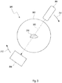
- Figure 2 for example shows a C-arm-based CT imaging device with the source 201 and the detector 202 rotating around the object to be imaged, in this case the patient's head 203.
- Figure 3 illustrates a top view of the C-arm scanner system shown in Figure 2 .
- Both the source 201, 304 and the detector 202, 306, which is preferably closed directly opposite to the source in one line through the object to be imaged 106, 203, 302, 310.
- the source 201, 304 and the detector 202, 306 are rotated around the patient 203, 302, 310.
- the rotation direction is indicated by reference numerals 204, 311, 312.
- the general CT acquisition process includes the source 201, 304, and the detector 202, 306 rotating around the patient 203, 302, 310 while measuring line integrals along the X-ray direction 308.
- the algorithm performing the method according to the invention is implemented on the HPC 103.
- the HCP 103 calculates the updated image in real time.
- standard CT density values and imaging features that are different from the standard CT values such as dual-energy index or difference images between actual projections and forward projected data sets are used to track instruments and to constrain the compressed sensing criterion.
- the updated image is then provided to the interventionist by displaying the updated image on the display array 102.
- display standard graphic volume display techniques such as volume-rendering, surface-rendering or digitally reconstructed radiographs (DDR) are calculated from the volumetric dataset.
- DDR digitally reconstructed radiographs
- the DDR are for example reconstructed from various angles which can depend on the radiologists selection or automatically depending on intrinsic imaging features so that the intervention guidance is optimized (e.g. perpendicular to the main movement direction of the catheter). Furthermore, angiographic features are incorporated into the DDR to provide a 3D road-mapping feature. All acquired projection images as well as all acquired temporal updates are stored in the HPC for later use, e.g. for a later reconstruction of bleedings and other modifications in soft tissue.
- the CT-scanner 101 can employ multiple X-ray sources as well as detectors up to arrays of X-ray sources combined with arrays of X-ray detectors.
- different X-ray energies can be used and the instrument can comprise material that allows detection in dual-energy mode.
- characteristic absorption features of the instruments with respect to multiple radiation energy can provide further information on the instrument and its movement. This allows to track instruments using other means than standard CT absorption measurements and the detection of instruments is more robust.
- Figure 4.1 illustrates a flowchart 400 of the general CT workflow for 4D-CATH as proposed according to the present invention.
- a number of projections fulfilling the Shannon-Nyquist criterion i.e. a high number of projections is acquired at different projection angles.
- a tomographic reconstruction of a high quality prior image is performed.
- the prior image serves as the first image of the object to be imaged.
- the instrument used during medical intervention on the object to be imaged is not present on the prior image. Therefore, the prior image comprises a volumetric image of the object to be imaged with high resolution prior to the intervention.
- such a first image may be provided from a database, a different imaging technique or a more coarsely sampled set of projections.
- step 402 an instrument, such as a catheter, may be placed for further medical intervention, e.g. on the heart.
- low dose update data is continuously acquired in step 403 for guiding the instrument during the intervention. Furthermore, the low dose update data from step 403 is continuously reconstructed using the imaging method according to the present invention.
- Figure 4.2 shows a flowchart 500 of the CT image acquisition and reconstruction.
- a high resolution, highly sampled CT scan is acquired as prior image.
- This image includes volumetric data representing the object to be imaged.
- the prior image is used as a first image incorporated in the iterative construction algorithm during the intervention.
- update information While performing the intervention by placing the instrument and moving it within the object to be imaged update information is continuously acquired in step 502.
- the update information comprises undersampled sets of projections, which allow for a low-dose rate.
- this update information is incorporated with the prior image in step 503.
- the update information including the change of information corresponding to the moving instrument can be reconstructed in step 504 providing updated image data.
- the static part of the image is provided by the prior image, while the update information comprising a set of undersampled projections provides the temporal changes, which correspond to the moving instrument.
- PRIDICT Prior Image Dynamic Computed Tomography
- the projections measured during the intervention in step 502 may after reconstruction in step 504 be used to update the prior image.
- any temporal changes occurring during the intervention such as movement of patient, can be incorporated over time into the prior image leading to a higher image quality.
- the update information comprising undersampled sets of projections may be collected in step 506 during the course of the intervention. After or during the intervention, but with a larger time delay than for 504, the collected data sets from step 506 may be reconstructed in step 508 to visualize changes on a slower time scale than instrument movements, such as bleedings.
- different reconstruction algorithms can be used, including algorithms with further sparsifying functions.
- Figure 5 shows an overview of the proposed reconstruction algorithm in relation to the amount of data that is acquired from the actual present (514).
- the continuous acquisition of low-dose tomographic data during the intervention 510 leads to a constantly increasing amount of projections from a time 514 (represents present) to a time 515 in the past.
- the longer ago from the present the higher the amount of low-dose tomographic data 512 that has been acquired.
- the amount of tomographic data 512 only comprises a few projections.
- Longer time ago 516 the amount of low-dose tomographic data 512 increases by increasing the number of projections measured.
- the number of projections measured during the intervention i.e. the amount of low-dose tomographic data 512, is increased.
- the measured data is used 518.2 to reconstruct and display temporal changes, such as movement of guide wires or catheters 526.
- the reconstruction in step 521 can, e.g. be performed by using compressed sensing, where the sparsifying is done through a difference with e.g. the first image.
- the full amount of low-dose tomographic data 512 corresponding to the projections measured until then can be used 518.1 to visualize the anatomy, bleedings, bones, organs or other static data 524.
- the reconstruction 520 can be performed using compressed sensing including further sparsifying functions such as gradient functions. The sparsifying functions can thereby be selected so that larger, more areal changes to the dataset will prevail, while shorter, more punctual changes will not be reconstructed.
- the data reconstructed after time period 516.2 may be fed back 528 into the reconstruction algorithm during intervention as a first image.
- Figure 6 illustrates how undersampled sets of projections 604 collected during the intervention may be defragmented for creating a fully sampled set of projections 602 which again may be used as updated first image (sliding prior).
- individual projections of the undersampled sets of projections 606 are culminated in accordance with their solid angle 608.
- the projections of the update scans 606 are acquired at angular positions that are different from earlier projection positions so that after several rotations a new-fully sampled dataset is produced which can be used as a sliding prior.
- the changes e.g. catheters, guidewires, etc.
- Such algorithms can be similar to those being used in metal artifact reduction, where the reconstruction including high contrast signals is followed by the segmentation of high contrast signals and the elimination of these high contrast structures in projection data via forward projection of segmented high contrast data. The new reconstruction can then be performed without high contrast data.
- algorithms that track instruments can be used. There e.g. connected pixels in the data set can be identified, a comparison with a data base of possible instruments can be performed or the PRIDICT (Prior Image Dynamic Computed Tomography) algorithm may even be modified so that significant pixels from the update will be memorized and removed.
- Other possibilities or additions may include dual-energy information e.g. through instruments, that provide a characteristic dual-energy signature.
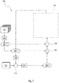
- Figure 7 shows a flowchart 700 illustrating the general structure of the PRIDICT reconstruction algorithm that can be used for 4D-CATH.
- the proposed algorithm PRIDICT is a reconstruction technique specialized to interventional 3D and 4D applications. It incorporates the information of a former scan (prior scan) to the reconstruction process and can reduce the number of relevant measurements for temporal updates far under the Shannon-Nyquist sampling using the compressed sensing framework.
- the interventional procedure starts with the acquisition of a fully sampled, normal dose scan 702 that can be used a prior image for the PRIDICT reconstruction algorithm as well as a first overview CT scan for the physician.
- This fully sampled scan can be reconstructed in step 704 through a standard CT reconstruction algorithm such as the FDK (Feldmann Davis Kress, as for example explained in Feldkamp LA, Davis LC, Kress JW. Practical cone-beam algorithm. J. Opt. Soc. Am. 1984;1(6):612-619 ) to provide a prior image 706.
- the prior image 706 forms the basis image 708 for the iterative PRIDICT reconstruction algorithm.
- undersampled sets of projections 712 are measured. These provide the update information including static as well as dynamic components of the object to be imaged.
- the image 708, which in the first iteration is equal to the prior image and includes volumetric data is projected in accordance with the projection angles measured in the undersampled set of projections 712.
- the projected data 710 from the image 708 is then subtracted individually from the update projections of the undersampled set of projections 712 in operation 714.
- difference images 716 which represent the difference between the undersampled set of projections and the projected prior image.
- difference images 716 are reconstructed through a standard reconstruction routine in CT such as FDK to provide a reconstructed and fully volumetric difference image 718.
- image 708, which in the first run corresponds to the prior image 706, is added to the volumetric difference image 718.
- image 706, which is the prior image and stays the prior image for every iteration is subtracted.
- various image processing and mathematical operations such as optimization routines, may be used to modify the image. This image is fed back into the iterative loop and serves as the base image 708 for the next iteration of the reconstruction algorithm.
- the PRIDICT algorithm 800 is illustrated including a minimization loop in place of the mathematical operations performed in step 724 of Figure 7 .
- a fully sampled set of projections 802 is measured, reconstructed via the FDK algorithm 804 to a volumetric data set 806, which is fed into the image 808 forming the basis of the PRIDICT algorithm.
- difference images 818 are reconstructed in 816 from the subtraction of the projections of the undersampled set of projections 812 and the projections projected from the image 808 in step 814.
- image 808 is added in step 820 following a subtraction of prior image 806 in step 822.
- the resulting image 824 excludes any static components and highlights the change happened in the intervention during the measurement of the undersampled set of projections 812.
- the embodiment of Figure 8 basically includes a minimization routing minimizing the number of significant pixels.
- the temporal updates are calculated as the FDK (Feldkamp-Davis-Kress) reconstruction of the difference of the actual measured projections and the calculated forward projections of the prior image.
- FDK Fedkamp-Davis-Kress
- These FDK reconstructions contain only information of the current changes in the image but include a large number of streaking artifacts. To reduce these streaking artifacts, the total number of significant pixels (represented by the L0 norm) has to be minimized.
- the minimization of the L0 norm is difficult, so the L1 norm can be minimized alternatively, e.g. by using the method of the steepest gradient, other convex optimization techniques can also be used.
- the global minimum would be a zero matrix; however in practice this would imply no changes in the volume so that the prior image and the current image are identically.
- the minimization step has to be adjusted to the FDK reconstruction step, so that raw data congruence is aimed. This is presented in the next paragraph.
- the global minimum of the L1 norm would be a zero matrix, but in fact this would eliminate any information in the update image.
- the link between the minimum number of independent probes and the number of significant pixels in the image m ⁇ S ln( N ) where NxN is the size of the reconstruction matrix, S is the number of significant pixels and m is the number of independent probes.
- L1 is minimized because of the mathematically difficulties minimizing L0.
- the actual aim is to minimize L0, so in an embodiment of the algorithm, other optimizations minimizing L0 casually or directly may be used, even if they do not minimize L1.
- Figure 9 includes a further sparsifying transform 936 performed before the minimization of the number of significant pixels. As sparsifying transform 936 gradient operations, wavelet transfomations, curvelet transformations, contourlet transformations or a combination therof can be used. This transform is then applied after reconstructing the difference 918 and before the minimization loop is entered in 924.
- step 936 it is also possible to use a combination of different transforms and/or tunable transformations, which can be used in different configurations during one reconstruction, to correctly reconstruct different structures point-like or curve-like structures.
- the weight of different sparsifying transforms can be varied e.g. according to the sparseness of the transformed image.
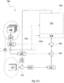
- FIG. 10.1 The realization of such a tunable PRIDICT reconstruction algorithm 1000 is shown in Figure 10.1 .
- the algorithm shown in Figure 10.1 corresponds to the algorithm shown in Figures 7 to 9 .
- the embodiment of Figure 10 incorporates the image processing and mathematical operations 1024 including the minimization loop 1028 for finding an optimal difference image and a pre-applied sparsifying function 1026.
- the sparsifying function as well as the minimization loop 1028 may be influenced by the actual difference 1030 given in the static prior set of projection 1002 and the undersampled set of projections 1012 including the temporal changes. So certain parameters of the mathematical functions, i.e.
- the sparsifying function and the minimization may be modified in accordance with a comparison 1030 done between the prior set of projections 1002 and the undersampled set of projections 1012.
- the reconstruction algorithm PRIDICT 1000 can be tuned and adapt to different situations depending on the temporal changes. This is particularly advantageous when reconstructing temporal changes from guide wires, catheters, tubes and the like or temporal changes which move much slower such as bleedings.
- FIG.2 shows further possibilities for influencing the reconstruction of updated images.
- the flowchart 1040 comprises in step 1042 the acquisition of undersampled imaging data during the intervention. From this data and the previously acquired prior image or an updated prior image the amount of difference and/or movement in the examined volume is calculated in step 1044. Then the calculated amount of difference and/or movement can be used to influence scan parameters and/or reconstruction parameters , such as the number of projections included into the undersampled set of projections, in step 1046. Optionally, such influences can also be triggered from the outside such as an operator 1052. Furthermore, these influences are used to vary the reconstruction algorithm 1048, such as reconstruction matrix size, time resolution, sparsifying function and so on. Lastly, a marker for the degree of completeness of the imaging data may be provided in operation 1050.
- Figure 11 shows another realization of the PRIDICT reconstruction algorithm 1100, which broadly corresponds to the reconstruction algorithm PRIDICT shown in Figures 7 to 9 .
- the subtraction 1114 is not only used to calculate the difference image 1116 but also to calculate the total modification 1120 in the image.
- the matrix size can be set 1122 which can be fed back to the difference reconstruction image 1118. This results in optimized reconstruction minimization of the significant number of pixels. Thus, if there is a large change the modifications are large and the matrix size may be smaller. On the other hand, if the changes between the prior image data and the undersampled set of projections are small, the modifications are small and the matrix size may be set to a larger value in order to reconstruct the difference properly.
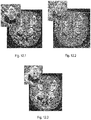
- Figure 12 illustrates the effect of the proposed PRIDICT reconstruction algorithm on a head.
- a pig head was scanned prior to the intervention, the result of which is shown in Figure 12.1 .
- Figure 12.2 shows the reconstruction of the undersampled set of projections using a standard FDK algorithm.
- Figure 12.2 includes streaks and artifacts.
- Figure 12.3 the result including the guide wire is shown reconstructed through the PRIDICT reconstruction that uses a fully sampled prior image and an undersampled set of projections.
- the result of Figure 12.3 is artifact-free and the magnified inset shows the wire labeled through the smaller arrow and the vessel through the larger arrow.
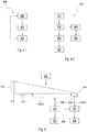
- Figure 13 illustrates different embodiments 1302, 1306, 1304 for motion compensated reconstruction in connection with the proposed PRIDICT reconstruction algorithm.
- a prior image 1308 reconstructed from a fully sampled set of projections 1312 includes different phases 1310 of the cardiac motion.
- the prior image 1308 results in a smeared image of the heart 1322, which is smeared by the heart motion during the measurement.
- the bottom part of column 1300 illustrates the corresponding undersampled set of projections where different projections represent different cardiac phases 1318 as well.
- the heart 1318 periodically changes appearance for the different cardiac phases 1318 from projection to projection 1316.
- Column 1302 illustrates one implementation for motion-gated reconstruction.
- a gating is performed to assort the acquisition into the heart cycle which itself is divided into phase bins with sufficiently small widths.
- the displacement of the heart is taken into account for e.g. each projection measured in the undersampled set of projections.
- the undersampled set of projections 1316 is binned into three different phases of the heart beat cycle 1324, 1326, 1327. These phases may for instance be monitored throughout the intervention, e.g. through electrocardiography, and the binning is carried out in accordance with the monitored reference signal.
- column 1306 another implementation of motion-compensated reconstruction via PRIDICT is illustrated.
- the prior image 1308 is binned into the cardiac phases 1334, 1336, 1338 rather than the reconstructed update image 1340.
- no gating signal is necessary for the reconstruction of the heart phases and thus, slower scanner systems might be utilized.
- Column 1304 shows another implementation of motion-gated reconstruction through PRIDICT.
- the prior as 1308 well as the time frames 1314 may be reconstructed with respect to the cardiac and/or respiratory phase using compressed sensing reconstruction.
- gating is necessary for the prior as well as the update image and images can be reconstructed with less motion-related smearing.
- the reconstruction scan can be incorporated with low dose update scans using motion-compensated reconstruction combined with compressed sensing and taking a 4D representation of the moving heart into consideration.
- the idea of motion-compensated 4D reconstruction may also be deeply integrated into the reconstruction algorithm. In order to do so, the cardiac and/or respiratory phases are registered or the transformation may be done through morphing or movement field. By using a transformation the image may be projected into either the moving space or a static space. In a static space the object to be imaged may be displayed in one phase only, which is particularly useful for the guidance of catheters. Furthermore, the requirements to the scanning speed are relaxed. With appropriate motion-compensating reconstruction algorithms (including movement vector fields) the data that is acquired at a certain heart phase can be used to reconstruct images at a different heart phase.
- Figure 14 shows an overview illustrating the capability of the PRIDICT reconstruction algorithm.
- a full dose prior image 1410 of the object to be imaged during intervention with a moving instrument low dose updates 1412 are acquired.
- a 4D data set of the moving instrument 1414 may be reconstructed.
- the low dose updates 1418 may be used to reconstruct the 3D data set of a body part with intervascular contrast media 1420.
- the 4D data set of the moving instrument 1414 and the 3D data set of the vascular structure 1420 can be merged to a 4D intervention guidance in 3D road-mapping 1416.
- the movement of the instrument during the intervention may be visualized after the intervention in the form of a roadmap illustrating the full course of the intervention.
- the present invention relates to an imaging message for radiologically guiding an instrument during medical interventions on an object using X-rays.
- the invention further refers to a system for radiologically guiding medical interventions on an object according to the proposed method.
- the method according to the present invention allows for dynamic imaging.
- dynamic imaging volumes are acquired in close, timely consecution.
- timely is used in the sense temporal or equivalently in the sense of different points in time.
- Volumetric describes that image data sets are reconstructed in 3 spatial dimensions.
- dynamic volumetric imaging describes 3D + time imaging or 4D imaging respectively.
- Dynamic imaging thus allows for controlling and monitoring interventions in three spatial dimensions. Such interventions are preferably performed on body parts, such as the cardiovascular system, tubular organ structures or on the brain, which exhibit complicated three dimensional structures.
- the time component, i.e. the dynamics, of interventions such as in catheter interventions, bronchoscopy interventions, implantation of cardiac pacemakers or positioning of stents, plays an important role in order assure save performance interventions.
- the systems and methods of the present application embody a method of 4D intervention guidance (named 4D-CATH which stands for 4D Catheter Advancement with Tomographic Help).
- the imaging is a tomographic system, such as a magnetic resonance imaging (MRI) scanner or a computed tomography (CT) scanner.
- MRI magnetic resonance imaging
- CT computed tomography
- RF radio frequency
- CT uses X-rays (a type of ionizing radiation) in order to image objects. Owing to the dose X-rays carry, only a restricted number of exposures can be performed and the number of projections to be measured is to be kept at a minimum.
- the imaging system utilized in connection with the present invention is a flat-panel cone-beam CT system and a CT reconstruction method to calculate 3D data of the examination volume.
- the examination volume is the volume that is being imaged or any part of it.
- the maximum size of the examination volume is limited due to the field of measurement of the tomographic system.
- Examination volume can include the patient and instruments in it.
- the examination volume is defined by physical characteristics of the scanner system.
- the CT data are continuously acquired to provide 4D information.
- the systems and methods of the present application as applied to intervention guidance provide 4D imaging during interventions. Some embodiments reduce the radiation dose during CT fluoroscopy, reduce imaging artifacts and provide the radiologist with 4D imaging data.
- Exemplary embodiments of the present application can comprise a CT reconstruction algorithm based on compressed sensing.
- the reconstruction can be based on McKinnon-Bates, PICCS or TRI-PICCS.
- the underlying CT reconstruction algorithm is based on prior knowledge of the scanned volume.
- Certain embodiments employ the prior knowledge of a prior data set that is updated with few CT projections during intervention.
- the update is preferably derived with a few projections or very low-dose projections.
- the reconstruction to combine a prior scan and the update information can preferably be an iterative CT reconstruction method, which can be based on the theory of compressed sensing.
- the prior data and update information can be acquired over a limited angle orbit around the patient.
- the reconstruction algorithm can use information that it derives by comparing the update scan with the prior scan to correct for limited angle CT reconstruction artifacts or distortions. This can be done by calculating a local distortion parameter by comparing the sparsely sampled limited angle updates with the well sampled prior scan.
- the continuously acquired data sets are collected and reconstructed from data collected throughout various amount of rotations, sampling rates and hence with a different time resolution and image qualities (SNR, soft-tissue contrast, etc.).
- the position of the projection positions might vary between rotations to acquire highly sampled data sets from several rotations.
- the system provides the radiologist with information about the degree of completeness of the data. In one embodiment this might be realized through variations in the reconstruction matrix size.
- One embodiment includes a system to track the interventionalists hands and avoid the radiation of the hands when they cross the direct X-ray beam area.
- One embodiment employs a registration algorithm that compensates for movements of the patient or system between acquisition of the prior scan and the update scans.
- a new prior image is constantly updated from the projection data.
- One embodiment includes iterative reconstruction algorithms, where the result of a former reconstruction (f-1) is used as the initial input of the actual reconstruction (f).
- an assumed three dimensional structure can be used as a first guess.
- the changes within the examined volumes are measured during intervention and the amount of changes influence the scan and imaging parameters (e.g. the number of projections used for the temporal update, the temporal resolution, the number of reconstructions shown to the interventionalist, the used sparsifying function, the X-ray tube current, the voltage, etc.).
- the amount of changes is a parameter proportional to the significant pixels; this can be the number of pixels that are different in the prior image and the temporal update. However, the amount of changes can also be proportional to the number of significant pixel in any domain that was used by the sparsifying function.
- the amount of changes are measured by comparing projections of the PRIOR with projections of the update scan; in one version of the embodiment, the amount of changes between consecutive scans are measured by calculating the difference images, in one version measured projections are compared with forward-projected projections.
- the amount of dose that is applied will be influenced by the amount of difference in the timely updates.
- the radiologist will get information about the degree of completeness of the reconstructed scan data. The uncertainty in the information will be expressed through a display or uncertainty in the reconstruction dataset.
- the algorithm incorporates information about the position of vessels from angiography in the reconstruction process. In one embodiment this is used to calculate a likelihood of vessel perforation, to even further reduce the amount of necessary projections for guide-wire guidance by assuming the most likely position of instruments will be within vessels.
- multiple X-ray sources work at different energies. Potential material differentiation is being used to influence the reconstruction algorithm. In one embodiment the dual-energy information is being used to which information changes are related to instrument movements.
- 4D digital subtraction angiographies are reconstructed to provide a 3D road map for intervention guidance.
- the 4D angiography is reconstructed by combining a highly-sampled prior scan without contrast media with sparsely-sampled updates that are acquired during the contrast media injection.
- Yet another embodiment relates to a computer readable medium having recorded instructions which, if executed by a computer, would cause a method to be performed.
- a method comprises (a) capturing a plurality of images; (b) optionally acquiring a prior imaging and timely updates during radiological interventions; and (c) combing the timely updates with the PRIOR, potentially using iterative CT reconstruction methods potentially based on compressed sensing.
- FIG. 1 shows an exemplarily configuration of the 4D-Cath-Lab with a closed gantry for continuous rotations (101), an array of displays (102), both connected to a high performance computing setup (103). All functions of the interventional CT systems and most parameters affecting the reconstruction can be controlled using the operator console (104). The position where the interventionist stands is marked as 105.
- FIG. 2 is an illustration of the image acquisition phase of a dynamic interventional C-arm CT imaging device with source (201) and detector (202) are rotating around the patient (203).
- FIG. 3 is an illustration of the general CT acquisition process with a circular trajectory (302), the source (304) and detector (306) rotating around the patient (310) while measuring line integrals along the X-ray direction (308).
- FIG. 4.1 is the flowchart of the general CT workflow for 4D-CATH.
- FIG. 4.2 is a flowchart of CT image acquisition and reconstruction.
- FIG. 7 is a flowchart showing the general structure of the PRIDICT reconstruction algorithm that can be used in 4D-CATH.
- FIG. 8 - 11 are potential variations of the PRIDICT algorithm.
- FIG. 10.1 is an example of a method to influence the sparsifying function and the update reduction function depending on the amount of differences in the update and prior projections.
- FIG. 5 illustrates one of the possible modifications to the proposed algorithm collecting projection and reconstruction datasets for a delayed reconstruction of soft tissue contrast.
- FIG. 10.2 is a flowchart showing a modification of the algorithm in which the continuous data acquisition process and image reconstruction algorithm is varied with respect to the actual differences/movements in the acquired volume.
- FIG. 10.2 Workflow to integrate the radiologists' input to influence the degree of changes to the image acquisition and reconstruction algorithm according to the amount of changes in the examined volume.
- FIG. 12 shows exemplarily reconstructions of a guide wire moved in a pig's head.
- Fully sampled standard reconstruction is compared to the undersampled standard reconstruction as well as to the PRIDICT reconstruction using fully sampled prior and undersampled temporal update.
- the prior is a fully sampled dataset reconstructed FDK (Feldkamp-Davis-Kress) algorithm (902).
- the update is a factor 20 under-sampled CT dataset of the same volume, but with the guide wire inserted, standard FDK reconstruction leads to 904, reconstruction of prior together with update using PRIDICT results in 906.
- One of the preferred embodiments of the algorithm is a gantry-based CT scanner system with a flat detector-based imaging chain ( FIG 1 ).
- Another embodiment consists of a C-arm or O-arm scanner geometry ( FIG 2 ).
- the algorithm can in general be used with any kind of imaging modality with a continuous tomographic acquisition.
- a continuously rotating CT gantry is the preferred implementation but e.g. alternating direction scanning C-arm systems can be used as well. Furthermore, various scanning trajectories can be incorporated. Additionally, multiple X-ray sources as well as detectors up to array X-ray sources combined with array X-ray detectors could be employed.
- the system can be run in a continuously tomographic acquisition mode and the image acquisition can be pulsed.
- the first rotation would be run in full sampled acquisition; all following rotations are performed with a fraction of projections acquired.
- the tomography system can be directly connected to a high performance computing setup (HPC) like conventional clusters, GPU-systems, GPU-clusters, cloud systems or other mainframes.
- HPC high performance computing setup
- the algorithm can be implemented into the HPC system; the system calculates the current image to be shown to the interventionist and displays it in various ways on the display array. This can happen in real-time.
- Standard graphic volume display techniques can be employed, such as volume-rendering, surface-rendering, etc.
- DDR digital reconstructed radiographs
- the DDR are reconstructed from various angles which can depend on the radiologists selection or automatically depending on intrinsic imaging features so that the intervention guidance is optimized (e.g. perpendicular to the main movement direction of the catheter).
- angiographic features are incorporated into the DDR to provide a 3D road-mapping feature.
- All acquired projection images as well as all acquired temporal updates may be stored in the HPC for later use, e.g. for a later reconstruction of bleedings and other modifications in soft tissue.
- the proposed Algorithm PRIDICT (Prior Image Dynamic Computed Tomography) ( FIG. 7 or 8 ) is a reconstruction technique specialized to interventional 3D and 4D applications. It incorporates the information of a former scan (prior image) to the reconstruction process and can reduce the number of relevant measurements for temporal updates far under the Shannon-Nyquist sampling using the compressed sensing framework.
- the prior scan may be fully sampled, meaning the number of measured projections comply with the Shannon-Nyquist theorem, while the temporal updates are highly undersampled and do not satisfy the Shannon-Nyquist theorem.
- the algorithm is described in three steps:
- the raw data-based image reconstruction can be divided in two separate categories, the reconstruction of the prior image and the reconstruction of the temporal updates.
- the reconstruction method of the prior image in generally is independent of the rest of the algorithm, every algorithm can be used assuming that the reconstructed prior image is free of artifacts and not dominated by noise.
- the temporal updates are calculated as the FDK (Feldkamp-Davis-Kress) reconstruction of the difference of the actual measured projections and the calculated forward projections of the prior image.
- FDK Fedkamp-Davis-Kress
- These FDK reconstructions contain only information of the current changes in the image but include a large number of streaking artifacts. To reduce these streaking artifacts, the total number of significant pixels (represented by the L0 norm) has to be minimized.
- the minimization of the L0 norm is difficult, so the L1 norm can be minimized alternatively, e.g. by using the method of the steepest gradient, other convex optimization techniques can also be used.
- the global minimum would be a zero matrix; however in practice this would imply no changes in the volume so that the prior image and the current image are identically.
- the minimization step has to be adjusted to the FDK reconstruction step, so that raw data congruence is aimed. This is presented in the next paragraph.
- the L1 norm may not be minimized directly, even optimizations minimizing L1 casually might be useful.
- L1 is minimized because of the mathematically difficulties minimizing L0.
- the actual aim is to minimize L0, so in an embodiment of the algorithm, other optimizations minimizing L0 casually or directly may be used, even if they do not minimize L1.
- wavelets, curvelets or contourlets can be used for the sparsifying transform.
- the sparsifying function might be applied after reconstruct the differences ( FIG. 9 ).
- a combination of different transforms may be used and/or one tunable transformation can be used in different configurations during one reconstruction to correctly reconstruct different structures as point-like or curve-like structures.
- the weight of different sparsifying transforms can be varied e.g. according to the sparseness of the transformed image.
- one method of the present application entails guidance of catheters, tubes, syringes, needles, guide-wires, coils, stents, vessel prosthesis and similar devices. Similarly intervention devices such as biopsy needles, drainage needles, catheters, thermo ablation and chemoembolization devices are imaged. Potentially visible embolization agents are visualized as well as contrast media of different kind.
- a combination of all acquired projections or a part of them can be used for a reconstruction of soft tissue images and/or changes, intracranial hemorrhage etc. This feature can be used for an intra-operative detection of possibly vessel damages. Therefore, the single temporal updates can be reprojected. Out of measured and calculated projections, a stationary projection without any moving structures can be calculated (e.g. by subtracting moved parts from the measured projections).
- a function to adopt the spatial resolution in the image (the image matrix) to the number of samples and the changes in the examined volume can be included.
- a method to calculate the changes and the sparsity in the used image domain is required, one possibility for that can be sum of squared differences of measured update projections and calculated forward projections ( FIG. 11 ).
- Preferred workflow looks as follows: The patient is placed in a continuously rotating CT gantry and scanned once with high dose and full sampling when the surgery starts. While the physician moves the guide wires and catheters, the CT system acquires undersampled CT datasets. The result of the reconstruction using a PRIDICT-based algorithm is displayed directly on the displays in different visualizations ( FIG. 4.2 ).
- FIG. 3 schematically depicts an exemplary imaging apparatus 300.
- Imaging apparatus 300 has a gantry 302 to carry source and detector devices 304 and 306, with a hollow center to allow the insertion of a test subject 310.
- Rotatable around the gantry 302 in the present example is a source 304, which can be, for example, an X-ray source for X-ray CT imaging.
- Source 304 produces radiation which travels in exemplary fashion along path 308, to reach detector 306. The radiation passes through subject 310.
- detector 306 records the intensity of the transmitted radiation.
- Both source 304 and detector 306 may be rotated about gantry 302 to capture a plurality of images at varying angles ⁇ , which may be measured from any cross-sectional line through the hollow 302.
- To be rotated about means to be positioned at more than one angle ⁇ along, allowing the acquisition of two or more images at different angles.
- Imaging apparatus 300 may preferably be a CT scanner (e.g. VCT, Siemens Medical Solutions, Forchheim, Germany), which includes a flat detector and a modified X-ray tube both mounted on a multi-slice CT gantry.
- the flat detector (PaxScan 4030CB, Varian Medical Systems, Palo Alto, CA) employed by this scanner consists of 2048 x 1536 detector pixels on an active area of 40 x 30 cm 2 resulting in a pixel size of 1942 ⁇ m 2 .
- X-ray photons are converted to light photons in a scintillation layer of thallium-doped caesium-iodine crystals which are subsequently detected by the photodiodes of the amorphous silicon wafer.
- the X-ray tube may be modified to increase the anode angle to increase the cone angle of the generated X-ray beam.
- the focal spot size can be reduced to 0.5 mm to decrease the effect of penumbral blurring. An even smaller focal spot is technically feasible. This may result in a reduced photon flux and could make advisable longer exposure times.
- the scanner's total scan field-of-view is 25 x 25 x 18 cm 3 .
- the active detector area may be reduced to 192 lines in z-direction and 1024 rows in x-y-direction to increase frame rate.
- the detector can be read out in a 2 x 2 binning mode, meaning that four neighbouring pixels are averaged. This results in a decreased scan field-of-view of 25 x 25 x 4.5 cm 3 , which is still large enough to cover the entire thorax and diaphragm of a rat.
- the resulting frame rate is 100 frames per second (fps), which translates into an exposure time of 10 ms per projection.
- the spatial resolution of the preferred scanner mentioned above, as computed by scanning a tungsten wire phantom, is 24 lp/cm at 10 % modulation transfer function. This isotropic spatial resolution translates into a minimal detectable feature size of 200 ⁇ m.
- Each projection image acquired during gantry rotation is time stamped and is labeled with the angle of acquisition. Scanner rotation times can be varied from 2 s to 19 s in steps of 1 s, the maximum total scan time being 80 s.
- the tomographic image reconstruction is based on a modified Feldkamp algorithm.
- a tube voltage of 80 kV and a tube current of 50 mA with continuous radiation may preferably be selected.
- FIG. 4 an overall method for generating intervention guidance image data according to the present application is depicted.
- continuous rotations are carried out, with one rotation being performed in 5 seconds.
- One hundred projections are generated per second, and each rotation is a full 360 degrees.
- the amount of projections acquired can be substantially reduced.
- the prior is acquired with 500 projections and for 4D intervention guidance a 2 second rotation time is used, together with 20 frames per second.
- PRIDICT or a variation of it, the continuous updates will be reconstructed.
- FIG. 9 The effect of the PRIDICT reconstruction algorithm is visualized in figure 9 .
- a pig corps' head was scanned prior the intervention and after the insertion of a guide wire into an arteria as a temporal update.
- the reconstruction of the fully sampled (902) and undersampled (904) temporal updates reconstructed using a standard FDK algorithm are shown.
- the PRIDICT reconstruction 906 that uses a fully sampled prior image and an undersampled temporal update is artifact free.
- angular positions within each rotation are not identical to angular positions within other rotations. This can be used to reconstruct more complete data sets (e.g. with a good soft-tissue contrast) by combining information from several rotations ( FIG. 7 ).
- the imaging system could be able to provide real-time updates of the imaged volume including instrument positions during interventions.
- the images are displayed in volume-rendering, surface rendering or such alike.
- 3D subtraction angiography can also be performed by subtracting projections or reconstructed volumes with or without contrast media.
- a 3D road-mapping feature can be integrated, here the contrasted vessels are superimposed in 3D on timely updates to guide the intervention.
- information of the vessel positions can be integrated into the reconstruction algorithm and can be used to manipulate the sparsifying function.
- the system can be built with several imaging chains, X-ray tubes and detectors.
- the angular distance between X-ray tubes can be 90°, for example.
- Different X-ray and detector systems can be employed, also in one system.
- the tube voltage can be varied to provide multi-energy information.
- the multi-energy information can be used to constrain the prior images, to detect changes in the volume (e.g. the different expression of guide-wire and tubing in multi-energy systems).
- the system can provide methods to vary the angular distance between projections and the angular distance over which one projection is acquired. This can be through a very fast x-ray on/off method, same kind of shutter or a frame work installed within the gantry.
- the system can be built so that it can provide all relevant features of current standard angiography C-arm system, which are X-ray fluoroscopy and digitial subtraction angiography. In one embodiment this can be done by parking the imaging chain at a certain angular position.
- the data acquisition is varied according to the amount of changes or movements in the examined volume.
- the differences of projections of several rotations are compared. In case of little differences the projection acquisition rate or radiation dose is reduced ( FIG 8 .). This can also be used to compensate patient movements that would yield great differences in the acquired projection data and hence require more radiation dose to compensate for it. This feature could be represented within the reconstruction algorithm as described in FIG 6 / 3 .
- the radiologist can influence the effects that the amount of differences has on the reconstruction algorithm or data acquisition ( FIG 9 ). E.g. by selecting certain programs or modes of the system and by pressing a handle or a pedal the radiation dose will be much more increased with the same amount of changes in the examined volume.
- the prior scan will be continuously updated by the continuous data acquisition.
- the prior will be generated out of the last 10 rotation consisting of projections that are acquired at slightly different angular positions.
- a spatial-registration algorithm is incorporated that registers the prior scan data with the update scan data using standard registration methods based in the projection or volume domain.
- the PRIDICT algorithm can be implemented in various ways using different sparsifying transforms.
- One of the simplest implementations is the use of the difference as sparsifying transform.
- Other possible transforms are e.g. the calculation of the gradient, a wavelet-sparsifying or a sparsification using dual energy concepts.
- a tunable function can be used representing different aspects of interventional tools ( FIG 9 ).
- the method for performing imaging during radiological interventions comprises the steps of measuring more than one set of projections of an object to be imaged at different points in time, wherein the measurement is performed by an imaging apparatus and dynamic reconstruction of volumetric datasets from the more than one set of projections, wherein the reconstruction is performed by processing means.
- the more than one set of projections of the object to be imaged are measured in a repetitive or continuous scanning mode of the imaging apparatus.
- the processing means comprise a processor.
- the more than one set of projections of the object to be imaged comprise undersampled sets of projections.
- the undersampled sets of projections are measured at consecutive points in time during the radiological intervention.
- the more than one set of projections of the object to be imaged comprises at least one fully sampled set of projections, preferably measured before, during or after the radiological intervention.
- the reconstruction is performed by an iterative reconstruction method.
- the iterative reconstruction method is based on compressed sensing theory.
- the variations in an algorithm for the reconstruction are matrix size, interruption criterion, sparsifying functions.
- the interruption parameter of the iterative reconstruction method is depending on the amount of changes in the volumetric datasets reconstructed from the undersampled sets of projections, the amount of significant pixels and/or the used sparsifying function.
- the more than one set of projections of the object to be imaged comprise at least one fully sampled set of projections and undersampled sets of projections measured at consecutive points in time during the radiological intervention, wherein the reconstruction is configured to combine the at least one fully sampled set of projections with undersampled sets of projections.
- imaging parameters of the imaging apparatus depend on the amount of movement and information changes in an examination volume.
- the dependency on the amount of movement and information changes in the examination volume is influenced by the interventionalist.
- the step of the reconstruction is influenced by the amount of changes in the object to be imaged.
- a user is provided with some means to influencing the ratio how changes in the examined volume influence the data acquisition, reconstruction parameters or data display.
- the method described above is for use during radiologically guided interventions on the cardiovascular system.
- the method described above is for use in the implantation of cardiac pacemakers.
- the method described above is for use during radiologically guided interventions on tubular organ structures, preferably lungs or kidneys.
- the method described above for use in positioning of stents in vessels or bronchi.
- the method described above is for use during bronchoscopy interventions.
- the method described above is for use during catheter interventions.
- the method described above is for use during radiologically guided interventions on the brain.
- a system for carrying out the method as described above contains an imaging apparatus in communication with processing means, wherein the imaging apparatus is a tomographic system, such as a magnetic resonance imaging (MRI) scanner or a computed tomography (CT) scanner.
- the computed tomography scanner comprises at least one X-ray source and at least one detector, wherein the X-ray sources differ in terms of the X-ray spectra or the detectors providing means of energy differentiation.
Claims (27)
- Ein bildgebendes Verfahren (400, 500, 1040) zur radiologischen Führung eines Instruments während medizinischen Eingriffen an einem Objekt (106, 203, 302), umfassend:a) Bereitstellung eines ersten Bildes (501, 602, 706, 806, 906, 1006, 1106) des besagten Objekts (106, 203, 302), gefolgt vonb) Bereitstellung aktualisierter Bilder (708, 808, 908, 1008, 1108), on-the-fly durch Echtzeitbildgebung während des Eingriffs an einen Operator (105) durch Messung eines unterabgetasteten Satzes von Projektionen (403, 502, 712, 812, 912, 1012, 1112) des besagten Objekts (106, 203, 302) und Rekonstruieren des besagten aktualisierten Bildes (708, 808, 908, 1008, 1108) unter Verwendung komprimierter Abtastung basierend auf Änderungen zwischen dem besagten ersten Bild (501, 602, 706, 806, 906, 1006, 1106) oder einer Aktualisierung des besagten ersten Bildes (602) und dem besagten unterabgetasteten Satz von Projektionen (403, 502, 712, 812, 912, 1012, 1112),wobei die Rekonstruktion durch komprimierte Abtastung eine iterative Minimierung einer Anzahl von signifikanten Pixeln (834, 1028) enthält, enthaltend mindestens eine weitere Sparsifying Funktion (936, 1026),
wobei die mindestens eine weitere Sparsifying Funktion (936, 1026), die in der Rekonstruktion enthalten ist, von der Menge der Daten abhängt, die vor dem aktuellen Zeitpunkt aufgenommen wurden, und
wobei die Anzahl der Projektionen in dem unterabgetasteten Satz von Projektionen (403, 502, 712, 812, 912, 1012, 1112) und die Dosisrate pro Projektion entsprechend der Menge von Änderungen zwischen Messungen (1046, 1030, 1120) angepasst werden. - Verfahren (400, 500, 1040) nach Anspruch 1, wobei das besagte bildgebende Verfahren auf ionisierender Strahlung basiert und der unterabgetastete Satz von Projektionen (403, 502, 712, 812, 912, 1012, 1112) mit einer minimierten Strahlungsdosis gemessen wird.
- Verfahren (400, 500, 1040) nach einem der Ansprüche 1 oder 2, wobei das erste Bild (501, 602, 706, 806, 906, 1006, 1106), die besagte Aktualisierung des besagten ersten Bildes (602) und besagte aktualisierte Bilder (708, 808, 908, 1008, 1108) volumetrische Bilder des Objekts umfassen.
- Verfahren (400, 500, 1040) nach einem der Ansprüche 1 oder 3, wobei das besagte erste Bild (501, 602, 706, 806, 906, 1006, 1106) ein hochaufgelöstes volumetrisches Bild des Objekts (106, 203, 302) umfasst, welches vor dem Eingriff aufgenommen wird, vorzugsweise basierend auf einem vollständig abgetasteten Satz von Projektionen, oder welches aus einer Datenbank bereitgestellt ist.
- Verfahren (400, 500, 1040) nach einem der Ansprüche 1 bis 4, wobei die besagte Aktualisierung des besagten ersten Bildes (602) das besagte erste Bild (501, 602, 706, 806, 906, 1006, 1106) und zumindest Teile von einem oder mehreren aktualisierten Bildern umfasst, die in früheren Durchläufen während des Eingriffes rekonstruiert wurden.
- Verfahren (400, 500, 1040) nach einem der Ansprüche 1 bis 5, wobei die besagte Aktualisierung des besagten ersten Bildes (602) ein gleitender Vorgänger ist, welcher aktualisierte Bilder von früheren Durchläufen defragmentiert.
- Verfahren (400, 500, 1040) nach einem der Ansprüche 1 bis 6, wobei die besagten unterabgetasteten Sätze von Projektionen (403, 502, 712, 812, 912, 1012, 1112), die on-the-fly gemessen sind, für eine verzögerte Rekonstruktion von Kontrast von weichem Gewebe gespeichert werden.
- Verfahren (400, 500, 1040) nach einem der Ansprüche 1 bis 7, wobei die Menge der besagten Änderungen durch Vorwärtsprojektion des besagten ersten Bildes (501, 602, 706, 806, 906, 1006, 1106) oder der besagten Aktualisierung des ersten Bildes (602) entsprechend den Projektionen, die in dem unterabgetasteten Satz von Projektionen (403, 502, 712, 812, 912, 1012, 1112) enthalten sind, bestimmt wird, die einen Satz von äquivalenten Projektionen basierend auf dem besagten ersten Bild (501, 602, 706, 806, 906, 1006, 1106) oder der besagten Aktualisierung des ersten Bildes (602) ergibt, und äquivalente Projektionen subtrahiert.
- Verfahren (400, 500, 1040) nach Anspruch 1, wobei aktualisierte Bilder ohne weitere Sparsifying Funktion rekonstruiert werden und wobei die Rekonstruktion von Daten, die von früheren Durchläufen gespeichert sind, wenigstens eine Sparsifying Funktion beinhaltet.
- Verfahren (400, 500, 1040) nach einem der Ansprüche 1 bis 9, wobei die Rekonstruktion durch die Menge der besagten Änderungen zwischen Messungen beeinflusst wird.
- Verfahren (400, 500, 1040) nach einem der Ansprüche 1 bis 10, wobei die Anzahl der Projektionen in dem unterabgetasteten Satz von Projektionen (403, 502, 712, 812, 912, 1012, 1112) und die Dosisrate pro Projektion entsprechend einer Eingabe (1052), die durch den Operator (105) vorgegeben wird, angepasst werden.
- Verfahren (400, 500, 1040) nach einem der Ansprüche 1 bis 11, wobei die Rekonstruktion des besagten aktualisierten Bildes (708, 808, 908, 1008, 1108) Bewegungskompensation (1302, 1304, 1306) umfasst.
- Verfahren (400, 500, 1040) nach einem der Ansprüche 1 bis 12, wobei periodische und / oder nicht-periodische Bewegung des Objekts (106, 203, 302) in der Rekonstruktion der besagten aktualisierten Bilder (708, 808, 908, 1008, 1108) kompensiert wird.
- Verfahren (400, 500, 1040) nach einem der Ansprüche 1 bis 13, wobei periodische Bewegungskompensation (1302, 1304, 1306) durch Eingruppierung von Bildern in verschiedene Phasen (1310 1318) der besagten periodischen Bewegung durchgeführt wird.
- Verfahren (400, 500, 1040) nach einem der Ansprüche 1 bis 14, wobei periodische Bewegungskompensation (1302, 1304, 1306) durch eine Transformation durchgeführt wird, welche die besagten aktualisierten Bilder (708, 808, 908, 1008, 1108), und / oder das besagte erste Bild (501, 602, 706, 806, 906, 1006, 1106) in eine Phase (1310, 1318) der besagten periodischen Bewegung zuordnet.
- Verfahren (400, 500, 1040) nach einem der Ansprüche 1 bis 15, wobei die besagten aktualisierten Bilder (708, 808, 908, 1008, 1108) auf einem Bildschirm angezeigt werden, unter Gestattung von unterschiedlichen Darstellungsarten, die automatisch oder durch den besagten Operator (105) ausgewählt werden.
- Das Verfahren (400, 500, 1040) wie beansprucht in einem der Ansprüche 1 bis 16 zur Verwendung in 4D radiologischer Führung.
- Das Verfahren (400, 500, 1040) wie beansprucht in einem der Ansprüche 1 bis 16, zur Verwendung während Eingriffen in das kardiovaskuläre System, zur Verwendung während Kathetereingriffen und / oder zur Verwendung bei der Implantation von Herzschrittmachern.
- Das Verfahren (400, 500, 1040) wie beansprucht in einem der Ansprüche 1 bis 16, zur Verwendung während Eingriffen an röhrenförmigen Organstrukturen, vorzugsweise Lungen oder Nieren, zur Verwendung bei der Positionierung von Stents in Gefäßen oder Bronchien oder zur Verwendung während Bronchoskopieeingriffen.
- Das Verfahren (400, 500, 1040) wie beansprucht in einem der Ansprüche 1 bis 16, zur Verwendung während Eingriffen am Gehirn.
- Ein System (100) zum radiologischen Führen medizinischer Eingriffe an einem Objekt (106, 203, 302) gemäß dem Verfahren wie beansprucht in einem der Ansprüche 1 bis 20, umfassend:- Mittel zur Bereitstellung eines ersten Bildes (501, 602, 706, 806, 906, 1006, 1106) des Objekts;- Eine bildgebende Vorrichtung, welche unterabgetastete Sätze von Projektionen (403, 502, 712, 812, 912, 1012, 1112) misst;- Verarbeitungsmittel in Verbindung mit der bildgebenden Vorrichtung zur Bereitstellung aktualisierter Bilder (708, 808, 908, 1008, 1108) on-the-fly durch Echtzeitbildgebung während des Eingriffes durch Rekonstruktion des besagten aktualisierten Bildes (708, 808, 908, 1008, 1108) unter Verwendung komprimierter Abtastung, basierend auf Änderungen zwischen dem besagten ersten Bild (501, 602, 706, 806, 906, 1006, 1106) oder einer Aktualisierung des besagten ersten Bildes (602) und dem besagten unterabgetasteten Satz von Projektionen (403, 502, 712, 812, 912, 1012, 1112),wobei die Rekonstruktion durch komprimierte Abtastung eine iterative Minimierung einer Anzahl von signifikanten Pixeln (834, 1028) enthält, enthaltend mindestens eine weitere Sparsifying Funktion (936, 1026),
wobei die mindestens eine weitere Sparsifying Funktion (936, 1026), die in der Rekonstruktion enthalten ist, von der Menge der Daten abhängt, die vor dem aktuellen Zeitpunkt aufgenommen wurden, und
wobei die Anzahl der Projektionen in dem unterabgetasteten Satz von Projektionen (403, 502, 712, 812, 912, 1012, 1112) und die Dosisrate pro Projektion entsprechend der Menge von Änderungen zwischen Messungen (1046, 1030, 1120) angepasst werden. - Das System (100) nach Anspruch 21, wobei die bildgebende Vorrichtung ein tomographisches System ist, wie beispielsweise ein Magnetresonanz-Bildgebungs (MRI) -Scanner oder ein Computertomographie (CT) Scanner.
- Das System (100) nach Anspruch 22, wobei der Computertomographie Scanner mindestens eine Röntgenquelle und mindestens einen Detektor umfasst.
- System (100) nach Anspruch 23, wobei sich die Röntgenstrahlungsquellen in Bezug auf die Röntgenstrahlenspektren oder die Detektoren, die Mittel zur Energiedifferenzierung bereitstellen, unterscheiden.
- Das System (100) wie beansprucht in einem der Ansprüche 21 bis 24, wobei Bildgebungsparameter der bildgebenden Vorrichtung automatisch oder durch einen Operator beeinflusst werden.
- Das System (100) wie beansprucht in einem der Ansprüche 21 bis 25, wobei das System Mittel zur Bereitstellung einer Ausgabe an einen Operator umfasst.
- Das System (100) wie beansprucht in einem der Ansprüche 21 bis 26, wobei die Ausgabe mindestens ein aktualisiertes Bild (708, 808, 908, 1008, 1108), mindestens ein Bild, das durch verzögerte Rekonstruktion von Kontrast von weichem Gewebe erzeugt ist und / oder einen Indikator für eine Genauigkeit der angezeigten Bilder umfasst.
Applications Claiming Priority (2)
| Application Number | Priority Date | Filing Date | Title |
|---|---|---|---|
| US201061425308P | 2010-12-21 | 2010-12-21 | |
| PCT/EP2011/073091 WO2012084726A1 (en) | 2010-12-21 | 2011-12-16 | Method and system for 4d radiological intervention guidance |
Publications (2)
| Publication Number | Publication Date |
|---|---|
| EP2656314A1 EP2656314A1 (de) | 2013-10-30 |
| EP2656314B1 true EP2656314B1 (de) | 2017-02-22 |
Family
ID=45420621
Family Applications (1)
| Application Number | Title | Priority Date | Filing Date |
|---|---|---|---|
| EP11802360.5A Active EP2656314B1 (de) | 2010-12-21 | 2011-12-16 | Verfahren und system für radiologische 4d-interventionsführung |
Country Status (3)
| Country | Link |
|---|---|
| US (2) | US10918305B2 (de) |
| EP (1) | EP2656314B1 (de) |
| WO (1) | WO2012084726A1 (de) |
Cited By (1)
| Publication number | Priority date | Publication date | Assignee | Title |
|---|---|---|---|---|
| DE102021003956A1 (de) | 2021-08-02 | 2023-02-02 | Ziehm Imaging Gmbh | Verfahren zum Betreiben eines medizinischen Bildgebungsgeräts zur lagerichtigen Darstellung von nicht-anatomischen Strukturen während einer bildgebenden Untersuchung und Vorrichtung hierfür |
Families Citing this family (22)
| Publication number | Priority date | Publication date | Assignee | Title |
|---|---|---|---|---|
| US8705828B2 (en) * | 2011-08-31 | 2014-04-22 | Carestream Health, Inc. | Methods and apparatus for super resolution scanning for CBCT system and cone-beam image reconstruction |
| WO2013111813A1 (ja) * | 2012-01-27 | 2013-08-01 | 株式会社 東芝 | 医用画像処理装置 |
| CN104428684B (zh) * | 2012-07-05 | 2017-10-24 | 皇家飞利浦有限公司 | 用于在强患者运动的情况中维持扫描的几何对齐的方法 |
| US9050056B2 (en) * | 2012-12-26 | 2015-06-09 | Biosense Webster (Israel) Ltd. | Reduced X-ray exposure by simulating images |
| US9269167B2 (en) * | 2013-01-28 | 2016-02-23 | Koninklijke Philips N.V. | SPECT motion-correction |
| KR102205353B1 (ko) * | 2013-09-26 | 2021-01-20 | 삼성전자주식회사 | 엑스선 촬영 장치 및 그 제어 방법 |
| CN104517263B (zh) * | 2013-09-30 | 2019-06-14 | Ge医疗系统环球技术有限公司 | 减少计算机断层扫描图像重构中伪像的方法和装置 |
| US9996954B2 (en) | 2013-10-03 | 2018-06-12 | Covidien Lp | Methods and systems for dynamic display of a trace of a physiological parameter |
| US20150198684A1 (en) * | 2014-01-13 | 2015-07-16 | Tamer BASHA | System and Method For Flexible Automated Magnetic Resonance Imaging Reconstruction |
| US10084669B2 (en) * | 2014-04-09 | 2018-09-25 | Centurylink Intellectual Property Llc | System and method for cloud computing adaptive cloud services |
| US10193769B2 (en) | 2014-05-16 | 2019-01-29 | Centurylink Intellectual Property Llc | Network services API |
| US9532757B2 (en) | 2014-06-30 | 2017-01-03 | General Electric Company | C-arm system and C-arm spin acquisition trajectories for dynamic imaging and improved image quality and method of use |
| CN104318595A (zh) * | 2014-10-21 | 2015-01-28 | 沈阳东软医疗系统有限公司 | Ct图像的运动向量场的计算方法及装置 |
| US20160206262A1 (en) * | 2015-01-21 | 2016-07-21 | General Electric Company | Extended volume imaging |
| US10796463B2 (en) | 2015-08-05 | 2020-10-06 | General Electric Company | Tomographic imaging for time-sensitive applications |
| DE102015215938A1 (de) * | 2015-08-20 | 2017-02-23 | Siemens Healthcare Gmbh | Verfahren zur lokalen Verbesserung der Bildqualität |
| JP6945322B2 (ja) * | 2017-03-31 | 2021-10-06 | キヤノンメディカルシステムズ株式会社 | 画像処理装置及びx線診断装置 |
| WO2018227465A1 (zh) * | 2017-06-15 | 2018-12-20 | 中山大学 | 一种基于稀疏正源分离模型的图像去模糊算法 |
| US20210233293A1 (en) * | 2018-05-04 | 2021-07-29 | Our United Corporation | Low-dose imaging method and apparatus |
| US11436766B2 (en) * | 2019-12-20 | 2022-09-06 | Varian Medical Systems International Ag | Tomographic image reconstruction using artificial intelligence (AI) engines |
| US11386592B2 (en) | 2019-12-20 | 2022-07-12 | Varian Medical Systems International Ag | Tomographic image analysis using artificial intelligence (AI) engines |
| US20230145920A1 (en) * | 2021-11-11 | 2023-05-11 | GE Precision Healthcare LLC | Systems and methods for motion detection in medical images |
Family Cites Families (8)
| Publication number | Priority date | Publication date | Assignee | Title |
|---|---|---|---|---|
| WO2005058137A2 (en) * | 2003-12-12 | 2005-06-30 | University Of Washington | Catheterscope 3d guidance and interface system |
| US7218702B2 (en) * | 2004-05-10 | 2007-05-15 | Wisconsin Alumni Research Foundation | X-ray system for use in image guided procedures |
| DE102005009085B4 (de) * | 2005-02-28 | 2008-07-31 | Siemens Ag | Computertomographie-Geräte, Steuereinrichtung für ein Computertomographie-Gerät und Verfahren zur Steuerung eines Computertomographie-Gerätes |
| DE602006010388D1 (de) | 2005-07-08 | 2009-12-24 | Wisconsin Alumni Res Found | Bildrekonstruktion unter Nebenbedingungen |
| EP1959397B1 (de) * | 2007-02-19 | 2019-08-07 | Wisconsin Alumni Research Foundation | Iterative HYPR-Rekonstruktion von medizinischen Bildern |
| US8031831B2 (en) * | 2009-05-28 | 2011-10-04 | Kabushiki Kaisha Toshiba | Voltage and or current modulation in dual energy computed tomography |
| US8111893B2 (en) * | 2009-06-09 | 2012-02-07 | Wisconsin Alumni Research Foundation | Method for dynamic prior image constrained image reconstruction |
| US8798353B2 (en) * | 2009-09-08 | 2014-08-05 | General Electric Company | Apparatus and method for two-view tomosynthesis imaging |
-
2011
- 2011-12-16 EP EP11802360.5A patent/EP2656314B1/de active Active
- 2011-12-16 US US13/991,550 patent/US10918305B2/en active Active
- 2011-12-16 WO PCT/EP2011/073091 patent/WO2012084726A1/en active Application Filing
-
2021
- 2021-01-15 US US17/150,205 patent/US20210128011A1/en active Pending
Non-Patent Citations (1)
| Title |
|---|
| BRIAN NETT ET AL: "LOW RADIATION DOSE C-ARM CONE-BEAM CT BASED ON PRIOR IMAGE CONSTRAINED COMPRESSED SENSING (PICCS): INCLUDING COMPENSATION FOR IMAGE VOLUME MISMATCH BETWEEN MULTIPLE DATA ACQUISITIONS", PROCEEDINGS OF SPIE, vol. 7258, 26 February 2009 (2009-02-26), pages 725803-1 - 725803-12, XP055199575, ISSN: 0277-786X, DOI: 10.1117/12.813800 * |
Cited By (2)
| Publication number | Priority date | Publication date | Assignee | Title |
|---|---|---|---|---|
| DE102021003956A1 (de) | 2021-08-02 | 2023-02-02 | Ziehm Imaging Gmbh | Verfahren zum Betreiben eines medizinischen Bildgebungsgeräts zur lagerichtigen Darstellung von nicht-anatomischen Strukturen während einer bildgebenden Untersuchung und Vorrichtung hierfür |
| EP4129189A1 (de) | 2021-08-02 | 2023-02-08 | Ziehm Imaging GmbH | Verfahren zum betreiben eines medizinischen bildgebungsgeräts zur lagerichtigen darstellung von nicht-anatomischen strukturen während einer bildgebenden untersuchung und vorrichtung hierfür |
Also Published As
| Publication number | Publication date |
|---|---|
| WO2012084726A1 (en) | 2012-06-28 |
| US20210128011A1 (en) | 2021-05-06 |
| US20130303884A1 (en) | 2013-11-14 |
| US10918305B2 (en) | 2021-02-16 |
| EP2656314A1 (de) | 2013-10-30 |
Similar Documents
| Publication | Publication Date | Title |
|---|---|---|
| US20210128011A1 (en) | Method and System for 4D Radiological Intervention Guidance (4D-cath) | |
| US8957894B2 (en) | System and method for four dimensional angiography and fluoroscopy | |
| JP5734664B2 (ja) | 希薄化制約補正を用いた画像復元法 | |
| US7782998B2 (en) | Method and apparatus for correcting motion in image reconstruction | |
| US7103136B2 (en) | Fluoroscopic tomosynthesis system and method | |
| US8811707B2 (en) | System and method for distributed processing of tomographic images | |
| US20030109779A1 (en) | MEDICAL image processing apparatus | |
| US8768030B2 (en) | CT measurement with multiple X-ray sources | |
| CN101902967B (zh) | 心脏ct中非自主呼吸运动的校正 | |
| US20140037049A1 (en) | Systems and methods for interventional imaging | |
| EP1966765A2 (de) | Verfahren zur bewegungskompensation von bilddaten | |
| JP2009236793A (ja) | 画像情報作成方法,断層撮影装置の断層画像情報作成方法及び断層撮影装置 | |
| US20140126685A1 (en) | Angiographic examination method | |
| US7379532B2 (en) | ECG-based rotational angiography for cardiology | |
| US8855391B2 (en) | Operating method for an imaging system for the time-resolved mapping of an iteratively moving examination object | |
| US20230130015A1 (en) | Methods and systems for computed tomography | |
| US20180235573A1 (en) | Systems and methods for intervention guidance using a combination of ultrasound and x-ray imaging | |
| Krebsforschungszentrum | FIELD OF INVENTION | |
| Zhu et al. | Cone-Beam CT for Vascular Imaging | |
| Patil et al. | Int J CARS (2009) 4 (Suppl 1): S311–S355 S339 | |
| Langet | Sampling and Motion Reconstruction in Three-dimensional X-ray Interventional Imaging |
Legal Events
| Date | Code | Title | Description |
|---|---|---|---|
| PUAI | Public reference made under article 153(3) epc to a published international application that has entered the european phase |
Free format text: ORIGINAL CODE: 0009012 |
|
| 17P | Request for examination filed |
Effective date: 20130704 |
|
| AK | Designated contracting states |
Kind code of ref document: A1 Designated state(s): AL AT BE BG CH CY CZ DE DK EE ES FI FR GB GR HR HU IE IS IT LI LT LU LV MC MK MT NL NO PL PT RO RS SE SI SK SM TR |
|
| DAX | Request for extension of the european patent (deleted) | ||
| 17Q | First examination report despatched |
Effective date: 20140714 |
|
| GRAP | Despatch of communication of intention to grant a patent |
Free format text: ORIGINAL CODE: EPIDOSNIGR1 |
|
| INTG | Intention to grant announced |
Effective date: 20160831 |
|
| STAA | Information on the status of an ep patent application or granted ep patent |
Free format text: STATUS: GRANT OF PATENT IS INTENDED |
|
| GRAS | Grant fee paid |
Free format text: ORIGINAL CODE: EPIDOSNIGR3 |
|
| GRAA | (expected) grant |
Free format text: ORIGINAL CODE: 0009210 |
|
| STAA | Information on the status of an ep patent application or granted ep patent |
Free format text: STATUS: THE PATENT HAS BEEN GRANTED |
|
| AK | Designated contracting states |
Kind code of ref document: B1 Designated state(s): AL AT BE BG CH CY CZ DE DK EE ES FI FR GB GR HR HU IE IS IT LI LT LU LV MC MK MT NL NO PL PT RO RS SE SI SK SM TR |
|
| REG | Reference to a national code |
Ref country code: GB Ref legal event code: FG4D |
|
| REG | Reference to a national code |
Ref country code: CH Ref legal event code: EP |
|
| REG | Reference to a national code |
Ref country code: AT Ref legal event code: REF Ref document number: 869797 Country of ref document: AT Kind code of ref document: T Effective date: 20170315 |
|
| REG | Reference to a national code |
Ref country code: IE Ref legal event code: FG4D |
|
| REG | Reference to a national code |
Ref country code: DE Ref legal event code: R096 Ref document number: 602011035262 Country of ref document: DE |
|
| REG | Reference to a national code |
Ref country code: NL Ref legal event code: FP |
|
| REG | Reference to a national code |
Ref country code: LT Ref legal event code: MG4D |
|
| REG | Reference to a national code |
Ref country code: AT Ref legal event code: MK05 Ref document number: 869797 Country of ref document: AT Kind code of ref document: T Effective date: 20170222 |
|
| PG25 | Lapsed in a contracting state [announced via postgrant information from national office to epo] |
Ref country code: HR Free format text: LAPSE BECAUSE OF FAILURE TO SUBMIT A TRANSLATION OF THE DESCRIPTION OR TO PAY THE FEE WITHIN THE PRESCRIBED TIME-LIMIT Effective date: 20170222 Ref country code: LT Free format text: LAPSE BECAUSE OF FAILURE TO SUBMIT A TRANSLATION OF THE DESCRIPTION OR TO PAY THE FEE WITHIN THE PRESCRIBED TIME-LIMIT Effective date: 20170222 Ref country code: FI Free format text: LAPSE BECAUSE OF FAILURE TO SUBMIT A TRANSLATION OF THE DESCRIPTION OR TO PAY THE FEE WITHIN THE PRESCRIBED TIME-LIMIT Effective date: 20170222 Ref country code: NO Free format text: LAPSE BECAUSE OF FAILURE TO SUBMIT A TRANSLATION OF THE DESCRIPTION OR TO PAY THE FEE WITHIN THE PRESCRIBED TIME-LIMIT Effective date: 20170522 Ref country code: GR Free format text: LAPSE BECAUSE OF FAILURE TO SUBMIT A TRANSLATION OF THE DESCRIPTION OR TO PAY THE FEE WITHIN THE PRESCRIBED TIME-LIMIT Effective date: 20170523 |
|
| PG25 | Lapsed in a contracting state [announced via postgrant information from national office to epo] |
Ref country code: LV Free format text: LAPSE BECAUSE OF FAILURE TO SUBMIT A TRANSLATION OF THE DESCRIPTION OR TO PAY THE FEE WITHIN THE PRESCRIBED TIME-LIMIT Effective date: 20170222 Ref country code: BG Free format text: LAPSE BECAUSE OF FAILURE TO SUBMIT A TRANSLATION OF THE DESCRIPTION OR TO PAY THE FEE WITHIN THE PRESCRIBED TIME-LIMIT Effective date: 20170522 Ref country code: RS Free format text: LAPSE BECAUSE OF FAILURE TO SUBMIT A TRANSLATION OF THE DESCRIPTION OR TO PAY THE FEE WITHIN THE PRESCRIBED TIME-LIMIT Effective date: 20170222 Ref country code: AT Free format text: LAPSE BECAUSE OF FAILURE TO SUBMIT A TRANSLATION OF THE DESCRIPTION OR TO PAY THE FEE WITHIN THE PRESCRIBED TIME-LIMIT Effective date: 20170222 Ref country code: PT Free format text: LAPSE BECAUSE OF FAILURE TO SUBMIT A TRANSLATION OF THE DESCRIPTION OR TO PAY THE FEE WITHIN THE PRESCRIBED TIME-LIMIT Effective date: 20170622 Ref country code: ES Free format text: LAPSE BECAUSE OF FAILURE TO SUBMIT A TRANSLATION OF THE DESCRIPTION OR TO PAY THE FEE WITHIN THE PRESCRIBED TIME-LIMIT Effective date: 20170222 Ref country code: SE Free format text: LAPSE BECAUSE OF FAILURE TO SUBMIT A TRANSLATION OF THE DESCRIPTION OR TO PAY THE FEE WITHIN THE PRESCRIBED TIME-LIMIT Effective date: 20170222 |
|
| PG25 | Lapsed in a contracting state [announced via postgrant information from national office to epo] |
Ref country code: EE Free format text: LAPSE BECAUSE OF FAILURE TO SUBMIT A TRANSLATION OF THE DESCRIPTION OR TO PAY THE FEE WITHIN THE PRESCRIBED TIME-LIMIT Effective date: 20170222 Ref country code: SK Free format text: LAPSE BECAUSE OF FAILURE TO SUBMIT A TRANSLATION OF THE DESCRIPTION OR TO PAY THE FEE WITHIN THE PRESCRIBED TIME-LIMIT Effective date: 20170222 Ref country code: CZ Free format text: LAPSE BECAUSE OF FAILURE TO SUBMIT A TRANSLATION OF THE DESCRIPTION OR TO PAY THE FEE WITHIN THE PRESCRIBED TIME-LIMIT Effective date: 20170222 Ref country code: IT Free format text: LAPSE BECAUSE OF FAILURE TO SUBMIT A TRANSLATION OF THE DESCRIPTION OR TO PAY THE FEE WITHIN THE PRESCRIBED TIME-LIMIT Effective date: 20170222 Ref country code: RO Free format text: LAPSE BECAUSE OF FAILURE TO SUBMIT A TRANSLATION OF THE DESCRIPTION OR TO PAY THE FEE WITHIN THE PRESCRIBED TIME-LIMIT Effective date: 20170222 |
|
| REG | Reference to a national code |
Ref country code: DE Ref legal event code: R097 Ref document number: 602011035262 Country of ref document: DE |
|
| PG25 | Lapsed in a contracting state [announced via postgrant information from national office to epo] |
Ref country code: SM Free format text: LAPSE BECAUSE OF FAILURE TO SUBMIT A TRANSLATION OF THE DESCRIPTION OR TO PAY THE FEE WITHIN THE PRESCRIBED TIME-LIMIT Effective date: 20170222 Ref country code: DK Free format text: LAPSE BECAUSE OF FAILURE TO SUBMIT A TRANSLATION OF THE DESCRIPTION OR TO PAY THE FEE WITHIN THE PRESCRIBED TIME-LIMIT Effective date: 20170222 Ref country code: PL Free format text: LAPSE BECAUSE OF FAILURE TO SUBMIT A TRANSLATION OF THE DESCRIPTION OR TO PAY THE FEE WITHIN THE PRESCRIBED TIME-LIMIT Effective date: 20170222 |
|
| REG | Reference to a national code |
Ref country code: FR Ref legal event code: PLFP Year of fee payment: 7 |
|
| PLBE | No opposition filed within time limit |
Free format text: ORIGINAL CODE: 0009261 |
|
| STAA | Information on the status of an ep patent application or granted ep patent |
Free format text: STATUS: NO OPPOSITION FILED WITHIN TIME LIMIT |
|
| 26N | No opposition filed |
Effective date: 20171123 |
|
| PG25 | Lapsed in a contracting state [announced via postgrant information from national office to epo] |
Ref country code: SI Free format text: LAPSE BECAUSE OF FAILURE TO SUBMIT A TRANSLATION OF THE DESCRIPTION OR TO PAY THE FEE WITHIN THE PRESCRIBED TIME-LIMIT Effective date: 20170222 |
|
| REG | Reference to a national code |
Ref country code: CH Ref legal event code: PL |
|
| REG | Reference to a national code |
Ref country code: IE Ref legal event code: MM4A |
|
| PG25 | Lapsed in a contracting state [announced via postgrant information from national office to epo] |
Ref country code: LU Free format text: LAPSE BECAUSE OF NON-PAYMENT OF DUE FEES Effective date: 20171216 Ref country code: MT Free format text: LAPSE BECAUSE OF NON-PAYMENT OF DUE FEES Effective date: 20171216 |
|
| REG | Reference to a national code |
Ref country code: BE Ref legal event code: MM Effective date: 20171231 |
|
| PG25 | Lapsed in a contracting state [announced via postgrant information from national office to epo] |
Ref country code: IE Free format text: LAPSE BECAUSE OF NON-PAYMENT OF DUE FEES Effective date: 20171216 |
|
| PG25 | Lapsed in a contracting state [announced via postgrant information from national office to epo] |
Ref country code: CH Free format text: LAPSE BECAUSE OF NON-PAYMENT OF DUE FEES Effective date: 20171231 Ref country code: LI Free format text: LAPSE BECAUSE OF NON-PAYMENT OF DUE FEES Effective date: 20171231 Ref country code: BE Free format text: LAPSE BECAUSE OF NON-PAYMENT OF DUE FEES Effective date: 20171231 |
|
| PG25 | Lapsed in a contracting state [announced via postgrant information from national office to epo] |
Ref country code: MC Free format text: LAPSE BECAUSE OF FAILURE TO SUBMIT A TRANSLATION OF THE DESCRIPTION OR TO PAY THE FEE WITHIN THE PRESCRIBED TIME-LIMIT Effective date: 20170222 Ref country code: HU Free format text: LAPSE BECAUSE OF FAILURE TO SUBMIT A TRANSLATION OF THE DESCRIPTION OR TO PAY THE FEE WITHIN THE PRESCRIBED TIME-LIMIT; INVALID AB INITIO Effective date: 20111216 |
|
| PG25 | Lapsed in a contracting state [announced via postgrant information from national office to epo] |
Ref country code: CY Free format text: LAPSE BECAUSE OF NON-PAYMENT OF DUE FEES Effective date: 20170222 |
|
| PG25 | Lapsed in a contracting state [announced via postgrant information from national office to epo] |
Ref country code: MK Free format text: LAPSE BECAUSE OF FAILURE TO SUBMIT A TRANSLATION OF THE DESCRIPTION OR TO PAY THE FEE WITHIN THE PRESCRIBED TIME-LIMIT Effective date: 20170222 |
|
| PG25 | Lapsed in a contracting state [announced via postgrant information from national office to epo] |
Ref country code: TR Free format text: LAPSE BECAUSE OF FAILURE TO SUBMIT A TRANSLATION OF THE DESCRIPTION OR TO PAY THE FEE WITHIN THE PRESCRIBED TIME-LIMIT Effective date: 20170222 |
|
| PG25 | Lapsed in a contracting state [announced via postgrant information from national office to epo] |
Ref country code: AL Free format text: LAPSE BECAUSE OF FAILURE TO SUBMIT A TRANSLATION OF THE DESCRIPTION OR TO PAY THE FEE WITHIN THE PRESCRIBED TIME-LIMIT Effective date: 20170222 Ref country code: IS Free format text: LAPSE BECAUSE OF FAILURE TO SUBMIT A TRANSLATION OF THE DESCRIPTION OR TO PAY THE FEE WITHIN THE PRESCRIBED TIME-LIMIT Effective date: 20170622 |
|
| PGFP | Annual fee paid to national office [announced via postgrant information from national office to epo] |
Ref country code: GB Payment date: 20231220 Year of fee payment: 13 |
|
| PGFP | Annual fee paid to national office [announced via postgrant information from national office to epo] |
Ref country code: NL Payment date: 20231219 Year of fee payment: 13 Ref country code: FR Payment date: 20231219 Year of fee payment: 13 Ref country code: DE Payment date: 20231221 Year of fee payment: 13 |