EP2654176A1 - Power supply apparatus and controlling mehtod of the same - Google Patents
Power supply apparatus and controlling mehtod of the same Download PDFInfo
- Publication number
- EP2654176A1 EP2654176A1 EP12184277.7A EP12184277A EP2654176A1 EP 2654176 A1 EP2654176 A1 EP 2654176A1 EP 12184277 A EP12184277 A EP 12184277A EP 2654176 A1 EP2654176 A1 EP 2654176A1
- Authority
- EP
- European Patent Office
- Prior art keywords
- power
- battery group
- power supply
- supply apparatus
- control unit
- Prior art date
- Legal status (The legal status is an assumption and is not a legal conclusion. Google has not performed a legal analysis and makes no representation as to the accuracy of the status listed.)
- Granted
Links
Images



Classifications
-
- H—ELECTRICITY
- H02—GENERATION; CONVERSION OR DISTRIBUTION OF ELECTRIC POWER
- H02J—ELECTRIC POWER NETWORKS; CIRCUIT ARRANGEMENTS OR SYSTEMS FOR SUPPLYING OR DISTRIBUTING ELECTRIC POWER; SYSTEMS FOR STORING ELECTRIC ENERGY
- H02J9/00—Circuit arrangements for emergency or stand-by power supply, e.g. for emergency lighting
- H02J9/04—Circuit arrangements for emergency or stand-by power supply, e.g. for emergency lighting in which the distribution system is disconnected from the normal source and connected to a standby source
- H02J9/06—Circuit arrangements for emergency or stand-by power supply, e.g. for emergency lighting in which the distribution system is disconnected from the normal source and connected to a standby source with automatic change-over, e.g. UPS systems
- H02J9/062—Circuit arrangements for emergency or stand-by power supply, e.g. for emergency lighting in which the distribution system is disconnected from the normal source and connected to a standby source with automatic change-over, e.g. UPS systems for AC powered loads
-
- H—ELECTRICITY
- H02—GENERATION; CONVERSION OR DISTRIBUTION OF ELECTRIC POWER
- H02J—ELECTRIC POWER NETWORKS; CIRCUIT ARRANGEMENTS OR SYSTEMS FOR SUPPLYING OR DISTRIBUTING ELECTRIC POWER; SYSTEMS FOR STORING ELECTRIC ENERGY
- H02J7/00—Circuit arrangements for charging or discharging batteries or for supplying loads from batteries
- H02J7/34—Parallel operation in networks using both storage and other DC sources, e.g. providing buffering
-
- H—ELECTRICITY
- H02—GENERATION; CONVERSION OR DISTRIBUTION OF ELECTRIC POWER
- H02J—ELECTRIC POWER NETWORKS; CIRCUIT ARRANGEMENTS OR SYSTEMS FOR SUPPLYING OR DISTRIBUTING ELECTRIC POWER; SYSTEMS FOR STORING ELECTRIC ENERGY
- H02J7/00—Circuit arrangements for charging or discharging batteries or for supplying loads from batteries
-
- H—ELECTRICITY
- H02—GENERATION; CONVERSION OR DISTRIBUTION OF ELECTRIC POWER
- H02J—ELECTRIC POWER NETWORKS; CIRCUIT ARRANGEMENTS OR SYSTEMS FOR SUPPLYING OR DISTRIBUTING ELECTRIC POWER; SYSTEMS FOR STORING ELECTRIC ENERGY
- H02J7/00—Circuit arrangements for charging or discharging batteries or for supplying loads from batteries
- H02J7/50—Circuit arrangements for charging or discharging batteries or for supplying loads from batteries acting upon multiple batteries simultaneously or sequentially
- H02J7/52—Circuit arrangements for charging or discharging batteries or for supplying loads from batteries acting upon multiple batteries simultaneously or sequentially for charge balancing, e.g. equalisation of charge between batteries
- H02J7/54—Passive balancing, e.g. using resistors or parallel MOSFETs
-
- H—ELECTRICITY
- H02—GENERATION; CONVERSION OR DISTRIBUTION OF ELECTRIC POWER
- H02J—ELECTRIC POWER NETWORKS; CIRCUIT ARRANGEMENTS OR SYSTEMS FOR SUPPLYING OR DISTRIBUTING ELECTRIC POWER; SYSTEMS FOR STORING ELECTRIC ENERGY
- H02J7/00—Circuit arrangements for charging or discharging batteries or for supplying loads from batteries
- H02J7/50—Circuit arrangements for charging or discharging batteries or for supplying loads from batteries acting upon multiple batteries simultaneously or sequentially
- H02J7/575—Parallel/serial switching of connection of batteries to charge or load circuit
-
- H—ELECTRICITY
- H02—GENERATION; CONVERSION OR DISTRIBUTION OF ELECTRIC POWER
- H02J—ELECTRIC POWER NETWORKS; CIRCUIT ARRANGEMENTS OR SYSTEMS FOR SUPPLYING OR DISTRIBUTING ELECTRIC POWER; SYSTEMS FOR STORING ELECTRIC ENERGY
- H02J7/00—Circuit arrangements for charging or discharging batteries or for supplying loads from batteries
- H02J7/50—Circuit arrangements for charging or discharging batteries or for supplying loads from batteries acting upon multiple batteries simultaneously or sequentially
- H02J7/52—Circuit arrangements for charging or discharging batteries or for supplying loads from batteries acting upon multiple batteries simultaneously or sequentially for charge balancing, e.g. equalisation of charge between batteries
- H02J7/56—Active balancing, e.g. using capacitor-based, inductor-based or DC-DC converters
-
- Y—GENERAL TAGGING OF NEW TECHNOLOGICAL DEVELOPMENTS; GENERAL TAGGING OF CROSS-SECTIONAL TECHNOLOGIES SPANNING OVER SEVERAL SECTIONS OF THE IPC; TECHNICAL SUBJECTS COVERED BY FORMER USPC CROSS-REFERENCE ART COLLECTIONS [XRACs] AND DIGESTS
- Y02—TECHNOLOGIES OR APPLICATIONS FOR MITIGATION OR ADAPTATION AGAINST CLIMATE CHANGE
- Y02B—CLIMATE CHANGE MITIGATION TECHNOLOGIES RELATED TO BUILDINGS, e.g. HOUSING, HOUSE APPLIANCES OR RELATED END-USER APPLICATIONS
- Y02B70/00—Technologies for an efficient end-user side electric power management and consumption
- Y02B70/30—Systems integrating technologies related to power network operation and communication or information technologies for improving the carbon footprint of the management of residential or tertiary loads, i.e. smart grids as climate change mitigation technology in the buildings sector, including also the last stages of power distribution and the control, monitoring or operating management systems at local level
-
- Y—GENERAL TAGGING OF NEW TECHNOLOGICAL DEVELOPMENTS; GENERAL TAGGING OF CROSS-SECTIONAL TECHNOLOGIES SPANNING OVER SEVERAL SECTIONS OF THE IPC; TECHNICAL SUBJECTS COVERED BY FORMER USPC CROSS-REFERENCE ART COLLECTIONS [XRACs] AND DIGESTS
- Y04—INFORMATION OR COMMUNICATION TECHNOLOGIES HAVING AN IMPACT ON OTHER TECHNOLOGY AREAS
- Y04S—SYSTEMS INTEGRATING TECHNOLOGIES RELATED TO POWER NETWORK OPERATION, COMMUNICATION OR INFORMATION TECHNOLOGIES FOR IMPROVING THE ELECTRICAL POWER GENERATION, TRANSMISSION, DISTRIBUTION, MANAGEMENT OR USAGE, i.e. SMART GRIDS
- Y04S20/00—Management or operation of end-user stationary applications or the last stages of power distribution; Controlling, monitoring or operating thereof
- Y04S20/20—End-user application control systems
Definitions
- the present invention relates to a power supply apparatus and a controlling method of the same.
- a power supply apparatus is an apparatus for temporarily supplying power to prevent damage to a load or save data the load processes when an abnormal situation occurs in a power source that supplies power to the load and thus a blackout occurs.
- the power supply apparatus includes an internal battery to store electric energy. When an abnormal situation occurs in a power source for supplying power to a load, as described above, the power supply apparatus supplies the electric energy stored in the battery to the load. Also, the power supply apparatus includes a battery controller for controlling the battery to detect a state of the battery or to control charge/discharge operations of the battery.
- the prevent invention provides a power supply apparatus including a plurality of battery groups of batteries and capable of stably supplying power to a load during a blackout or during a particular time period, and a controlling method of the same.
- a power supply apparatus comprising an input terminal adapted to receive an external AC power; an output terminal adapted to output a first AC power, a first power conversion unit adapted to convert the received external AC power to a first DC power and outputs the first DC power; a second power conversion unit adapted to convert a DC power to a first AC power and outputs the first AC power to the output terminal; a first node electrically connected between the output of the first power conversion unit and the input of the second power conversion unit; a control unit adapted to control the operations of the first and second power conversion units; and a first and a second battery group each connected to the control unit and electrically connectable to first node.
- the first and second battery groups are distinct from each other and can be separately connected to the first node.
- the control unit is adapted to dynamically allocate one of the first and the second battery group as a first dynamic battery group and the other of the first and the second battery group as a second dynamic battery group depending on a predetermined condition, wherein the first dynamical group acts in a power supply mode, and the second dynamic battery group acts in a standby mode.
- the power supply apparatus may further comprise a bypass circuit electrically connected to the input terminal and the output terminal to bypass the first and second power conversion units.
- the power supply apparatus preferably further comprises a first switching unit connected between the input terminal of the power supply apparatus and the input of the first power conversion unit, and a second switching unit electrically connected between the output of the second power conversion unit and the output terminal of the power supply apparatus, wherein the control unit is adapted to control the operation of the first and second switching elements.
- the power supply apparatus may further comprise a third switching unit electrically connected on one end to the first node and on the other end to the first battery group, and a fourth switching unit electrically connected on one end to the first node and on the other end to the second battery group, wherein the control unit is adapted to control the operation of the third and fourth switching elements such that the first dynamic battery group is connected to the first node and the second dynamic battery group is not connected to the first node.
- the control unit is preferably adapted to determine a normal operation state, and the predetermined condition corresponds to a first emergency situation, which corresponds to a blackout at the input terminal.
- the predetermined condition may further correspond to a second emergency situation, which corresponds to the case where a power for a load at the output terminal of the power supply apparatus exceeds the power at the input terminal.
- control unit Upon the determination of an end of the first or second emergency situation, respectively, the control unit is adapted to stop supplying energy of the first dynamic battery group and is adapted to electrically connect the input terminal to the respective first dynamic battery group to recharge the first dynamic battery group.
- control unit is preferably adapted to control supply of the external AC power to the output terminal of the power supply apparatus in addition to the energy of the first dynamic battery group.
- the control unit may be further adapted to compare a state of charge of the first and second battery groups such that the battery group with higher state of charge is used for power supply.
- the control unit may be further adapted to compare a count or number of use of the first and second battery groups such that the battery group with the lower number or count of use is used for power supply.
- the control unit may be further adapted to compare the temperature of the first and second battery groups such that the battery group with lower temperature is used for power supply.
- the control unit may be further adapted to control supply of the input external AC power to the output of the power supply apparatus in a normal operation state.
- a battery management system may be further provided adapted to control charging and discharging of the first and second battery group, wherein the battery management system is connected to the control unit.
- the power supply apparatus may further comprise a plurality of temperature sensors for measuring the temperature of the first and second battery group.
- the control unit may be further adapted to change assignment of a first or second battery group to the first dynamic battery group if the electric energy stored in the assigned battery group falls below the required energy level.
- batteries provided in a power supply apparatus are formed in a plurality of battery groups, and thus, according to the type of emergency, while any one battery group operates in a power supply mode, another battery group operates in a standby mode so that power may be stably supplied to a load.
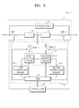
- FIG. 1 is a block diagram illustrating a power supply apparatus 1 according to an embodiment of the present invention.
- the power supply apparatus 1 includes a power supply circuit 10, a battery pack 14, and a control unit 17. Also, the power supply apparatus 1 includes an input terminal "in” and an output terminal "out”.
- Power from an external power source is applied to the input terminal "in" to be supplied to a load.
- the output terminal "out” may be connected to the load and outputs an external power to the load. Also, when a blackout is caused by a malfunction of the external power source or an overload is generated as supplied power exceeds a maximum supplied power for a particular time period, the output terminal "out” may use electric energy stored in a battery 15 to output a first AC power to the load.
- the power supply circuit 10 supplies power for operations of the load and a battery management system (BMS) 16.
- the power supply circuit 10 may include a bypass circuit 11, a first switching element SW1-1, a second switching element SW1-2, and a first power conversion unit 12, and a second power conversion unit 13.
- the bypass circuit 11 is connected between the input terminal "in” and the output terminal "out” and transfers the external power directly to the output terminal "out” without conversion.
- the first switching element SW1-1 is controlled to supply the external power applied from the input terminal "in” to the first power conversion unit 12.
- the first switching element SW1-1 in an ON state supplies the external power to the first power conversion unit 12.
- the first switching element SW1-1 in an OFF state stops the supply of the external power to the first power conversion unit 12.
- the ON/OFF operations of the first switching element SW1-1 may be controlled by the control unit 17.
- the first power conversion unit 12 is connected between the first switching element SW1-1 and a first node N1, and converts received external power to a first DC power and outputs the first DC power to the first node N1.
- the first power conversion unit 12 may be a rectifier or a converter for converting AC to DC.
- the first power conversion unit 12 makes a voltage that may be used for charging the battery 15.
- the second power conversion unit 13 is connected between the first node N1 and the second switching element SW1-2.
- the second power conversion unit 13 converts the DC power from the first power conversion unit 12 or the electric energy stored in the battery 15 to a first AC power and outputs the first AC power.
- the second power conversion unit 13 may be an inverter for converting DC to AC.
- the second power conversion unit 13 makes a voltage that may be used by the load.
- the second power conversion unit 13 may make a feature, such as an amplitude or phase, of the first AC power that is output substantially the same as that of the external power.
- the second switching element SW1-2 controls so that the first AC power output from the second power conversion unit 13 is supplied to the output terminal "out".
- the second switching element SW1-2 in an ON state supplies the first AC power to the output terminal "out”.
- the second switching element SW1-2 in an OFF state stops the supply of the first AC power to the output terminal "out”.
- the ON/OFF operations of the second switching element SW1-2 may be controlled by the control unit 17.
- the battery pack 14 stores electric energy and supplies the electric energy to the load for emergency situations.
- an emergency situation may be divided into a first emergency situation and a second emergency situation.
- the first emergency situation is a case in which a blackout is caused by a malfunction of the external power source.
- the second emergency situation is a case when a load power exceeds a supplied power due to an abrupt change in the load for a particular time period.
- the particular time period may be a time period between noon to 2 p.m. in the summer season and a time period between 10 p.m. to midnight in the winter season, or a time period between July to August in the summer season and a time period between December to February in the winter season.
- the particular time period is not limited to the above examples.
- the battery pack 14 includes the battery 15, the BMS 16, a third switching element SW2-1, and a fourth switching element SW2-2.
- the battery 15 is a rechargeable secondary battery.
- the battery 15 may be formed by serially and/or parallelly connecting a plurality of battery cells, or by serially and/or parallelly connecting battery modules, each battery module including a plurality of battery cells. Since the battery 15 supplies electric energy to the load when an emergency situation occurs, a battery cell exhibiting a large capacity characteristic may be used as the battery cell.
- the battery 15 may include at least one battery cell.
- the battery 15 may be a rechargeable secondary battery such as a nickel-cadmium battery, a nickel metal hydride (NiMH) battery, a lithium ion battery, and a lithium polymer battery.
- the battery 15 may be used by being divided into a first battery group 15-1 and a second battery group 15-2.
- the first battery group 15-1 may include at least one battery and the second battery group 15-2 may include at least one battery. Also, when N-number of batteries exist, at least one battery may be selected as the first battery group 15-1 and the other batteries may be selected as the second battery group 15-2.
- the first battery group 15-1 and the second battery group 15-2 may operate in different modes according to an emergency situation.
- the battery 15 may be defined as a first dynamic battery group and a second dynamic battery group.
- the first dynamic battery group is defined as the first battery group 15-1 or the second battery group 15-2 operating in the power supply mode and the second dynamic battery group is defined as the first battery group 15-1 or the second battery group 15-2 operating in the standby mode.
- the control unit 17 may assign the battery 15 to one of the first and second dynamic battery groups variously according to a type of an emergency situation, a state of charge (SOC) of a battery, a frequency that a battery group operates in the power supply mode, or a temperature of a battery. Also, the control unit 17 may change assignment of the first or second dynamic battery group during the operation of the power supply apparatus 1.
- SOC state of charge
- the first battery group 15-1 may be assigned to a first dynamic battery group to operate in a power supply mode and the second battery group 15-2 may be assigned to a second dynamic battery group to operate in a standby mode. Under the first emergency situation, the first battery group 15-1 may supply the stored electric energy to the load. When the first emergency situation is finished, the first battery group 15-1 is recharged with electric energy.
- the second battery group 15-2 may be assigned to the first dynamic battery group to operate in the power supply mode and the first battery group 15-1 may be assigned to the second dynamic battery group to operate in the standby mode.
- the second battery group 15-2 may supply the stored electric energy to the load.
- the external power from the input terminal "in” may be transferred to the output terminal "out” via the bypass circuit 11 and simultaneously the electric energy stored in the second battery group 15-2 may be supplied to the load.
- the second battery group 15-2 is recharged with electric energy.
- a first emergency situation and a second emergency situation are set to be a first cycle
- the operation of the battery group 15 in the first cycle and in a second cycle is as follows.
- the first battery group 15-1 may be assigned to the first dynamic battery group and the second battery group 15-2 may be assigned to the second dynamic battery group.
- the second battery group 15-2 may be assigned to the first dynamic battery group and the first battery group 15-1 may be assigned to the second dynamic battery group.
- the second battery group 15-2 may be assigned to the first dynamic battery group and the first battery group 15-1 may be assigned to the second dynamic battery group. Also, if the second emergency situation of the second cycle occurs, the first battery group 15-1 may be assigned to the first dynamic battery group and the second battery group 15-2 may be assigned to the second battery group 15-2.
- the electric energy stored in the second battery group 15-2 or the first battery group 15-1 operating in the standby mode may be supplied instead to the load.
- the first battery group 15-1 may be recharged.
- the second battery group 15-2 or the first battery group 15-1 assigned to the second dynamic battery group may be recharged.
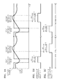
- FIGS. 2A to 2C are views illustrating operational states of the power supply apparatus 1 according to a change in power, including the first and second cycles, in which FIG. 2A illustrates a supplied power and a load power, FIG. 2B illustrates an operational state of the first battery group 15-1 under an emergency situation, and FIG. 2C illustrates an operational state of the second battery group 15-2 under an emergency situation.
- FIGS. 2A to 2C illustrates that a first emergency situation first occurs in the first and second cycles and a second emergency situation occurs later
- the present invention is not limited thereto so that the second emergency situation may first occur and the second emergency situation may occur later.
- the same emergency situation may occur in a plurality of times in the same single cycle.
- a section 201 of the first battery group 15-1 is a section in which a blackout occurs and the power supply apparatus 1 is returned to a normal state.
- the section 201 may be divided into a section 201-1 and a section 201-2.
- the section 201-1 is a section in which a blackout actually occurs and the section 201-2 is a section in which the blackout is finished and the power supply apparatus 1 is returned to a normal state.
- the supply of power by the first battery group 15-1 may not be finished instantly when the section 201-1 ends, and may be gradually decreased until the power supply apparatus 1 is returned to a normal state or maintained for a predetermined time, in the section 201-2.
- the second battery group 15-2 assigned to the first dynamic battery group operates in the power supply mode and the first battery group 15-1 assigned to the second dynamic battery group operates in the standby mode.
- a section 202 of the second battery group 15-2 is a section in which the power needed for a load in the second emergency situation is returned to a normal state and thus the power supply apparatus 1 operates in the normal state.
- the section 202 may be divided into a section 202-1 and a section 202-2.
- the section 202-1 is a section from a time point when a blackout is caused because the load power exceeds the supplied power due to an abrupt change in the load in a particular time period to a time point when the load power is returned to a normal state.
- a time point of the section 202 that is, a time point when the second emergency situation occurs, may be a time point when the supplied power matches the load power as illustrated in FIG. 2A or a time point before the time point when the supplied power matches the load power.
- the section 202-2 is a section in which the power supply apparatus 1 is returned to the normal state after the load power is returned to the normal state. In FIG. 2C , the supply of power by the second battery group 15-2 may not be finished instantly when the section 202-1 ends, and may be gradually decreased until the power supply apparatus 1 is returned to the normal state or maintained for a predetermined time, in the section 202-2.
- the second battery group 15-2 assigned to the first dynamic battery group operates in the power supply mode and the first battery group 15-1 assigned to the second dynamic battery group operates in the standby mode. Also, when the second emergency situation of the second cycle occurs, the first battery group 15-1 assigned to the first dynamic battery group operates in the power supply mode and the second battery group 15-2 assigned to the second dynamic battery group operates in the standby mode.
- the reason for switching the assignment of the first and second dynamic battery groups when the emergency situations of the first and second cycles occur is to prevent imbalance in the battery groups caused by the continuous operation of any one battery group in the power supply mode or the standby mode.
- the assignment of the first and second battery groups may be determined based o the following standard.
- states of charge (SOC) stored in the first and second battery groups 15-1 and 15-2 are compared with each other. According to a result of the comparison, any one of the first and second battery groups 15-1 and 15-2 having a larger SOC may be assigned to the first dynamic battery group and one having a smaller SOC may be assigned to the second dynamic battery group.
- SOCs of the first and second battery groups 15-1 and 15-2 are the same, as described above, the assignment of the first and second dynamic battery groups may be determined according to the type of an emergency situation.
- the measurement and comparison of the SOCs of the first and second battery groups 15-1 and 15-2 are performed by the BMS 16 that is described later.
- the frequencies that the first and second battery groups 15-1 and 15-2 operate as the first dynamic battery group during a previous emergency situation are determined. Then, any one of the first and second battery groups 15-1 and 15-2 having a less frequency of operating as the first dynamic battery group may be assigned to the first dynamic battery group, whereas the other battery group may be assigned to the second dynamic battery group.
- a current temperature and a reference temperature of the first and second battery groups 15-1 and 15-2 are compared with each other. Then, any one of the first and second battery groups 15-1 and 15-2 having a lower temperature may be assigned to the first dynamic battery group, whereas the other battery group may be assigned to the second dynamic battery group.
- a first temperature sensor 18-1 and a second temperature sensor 18-2 may be included as illustrated in FIG. 3 .
- the first and second temperature sensors 18-1 and 18-2 may be thermistors, but not limited thereto.
- the third switching element SW2-1 connected between the first node N1 and the first battery group 15-1 may store electric energy in the first battery group 15-1 or output electric energy from the first battery group 15-1.
- the third switching element SW2-1 is in an ON state under the first emergency situation and supplies the electric energy stored in the first battery group 15-1 to the second power conversion unit 13. After the first emergency situation is finished, the third switching element SW2-1 may be switched to an OFF state and then switched back to the ON state.
- the third switching element SW2-1 When the third switching element SW2-1 is switched back to the ON state, the first battery group 15-1 may be recharged with the first DC power from the first power conversion unit 12.
- the ON/OFF operations of the third switching element SW2-1 may be controlled by the BMS 16.
- the fourth switching element SW2-2 connected between the first node N1 and the second battery group 15-2 may store electric energy in the second battery group 15-2 or output electric energy from the second battery group 15-2.
- the fourth switching element SW2-2 is exemplarily in an ON state under the second emergency situation and supplies the electric energy stored in the second battery group 15-2 to the second power conversion unit 13. After the second emergency situation is finished, the fourth switching element SW2-2 is in an ON state so that the first battery group 15-1 may be recharged with the first DC power from the first power conversion unit 12.
- the ON/OFF operations of the fourth switching element SW2-2 may be controlled by the BMS 16.
- the BMS 16 controls charge and discharge of the battery 15.
- the BMS 16 operates as a protection circuit.
- the BMS 16 may include an analog front end (AFE) (not shown) for sensing a voltage, a current, and a temperature of the battery 15, and a microcomputer (not shown) for controlling an operation of the AFE and transferring data to the control unit 17 or an external monitoring apparatus (not shown).
- AFE analog front end
- the BMS 16 performs a sensing operation and a communication operation not only when the battery 15 performs a charge or discharge operation but also in a normal state.
- the BMS 16 outputs a switching control signal for switching the third switching element SW2-1 or the fourth switching element SW2-2 according to the type of emergency situation. As described above, when receiving generation of the first emergency situation from the control unit 17, the BMS 16 may output a control signal to turn the third switching element SW2-1 on. When receiving generation of the second emergency situation from the control unit 17, the BMS 16 may output a control signal to turn the fourth switching element SW2-2 on. Also, when receiving termination of the first or second emergency situation from the control unit 17, the BMS 16 may turn the third or fourth switching element SW2-1 or SW2-2 on to charge the first or second battery group 15-1 or 15-2.
- the BMS 16 may output a switching control signal for switching the third or fourth switching element SW2-1 or SW2-2 by measuring and comparing the SOCs of the first and second battery groups 15-1 and 15-2, measuring the frequency of operations as the first dynamic battery group in a previous emergency situation, or comparing the measured temperatures of the first and second battery groups 15-1 and 15-2 with each other.
- the BMS 16 may simultaneously turn the third and fourth switching elements SW2-1 and SW2-2 on or off, or turn one switching element on while turning the other switching element off.
- the control unit 17 controls an operation of each of the elements of the power supply apparatus 1.
- the controller 17 controls the ON/OFF operations of the first and second switching elements SW1-1 and SW1-2.
- the control unit 17 supplies electric power by turning the first switching element SW1-1 on to charge the battery 15.
- the control unit 17 turns the second switching element SW1-2 on so that the electric energy stored in the battery 15 may be supplied to the load.
- the control unit 17 senses an abnormal state of the external power source and, when an emergency situation occurs, controls the power supply apparatus 1 to operate as an uninterruptible power supply (UPS). In other words, the control unit 17 controls the external power to be transferred to the load in a normal state in which the external power source supplies electric power to the load, and controls the power supply circuit 10 to generate an operation power of the BMS 16 by using the external power. Also, when a blackout is caused by a malfunction of the external power source or an overload is generated as supplied power exceeds a maximum supplied power for a particular time period, the control unit 17 controls the power supply circuit 10 to generate electric power to be supplied to the load and the operation power of the BMS 16 by using the electric energy stored in the battery 15.
- UPS uninterruptible power supply
- a method of supplying an operation power of the BMS 16 in the power supply apparatus 1 according to the present embodiment is described below.
- FIG. 4A /B is a flowchart showing a method of controlling the power supply apparatus 1, according to an embodiment of the present invention.
- the control unit 17 selects at least one of a plurality batteries as the first battery group 15-1 and the other batteries as the second battery group 15-2, and then assigns the first dynamic battery group to operate in the power supply mode and the second dynamic battery group to operate in the standby mode (S401).
- control unit 17 may determine whether the first emergency situation occurs in which a blackout is caused due to the malfunction of the external power or overload (S403).
- the control unit 17 turns the first switching element SW1-1 off and the second switching element SW1-2 on (S405).
- the first switching element SW1-1 is turned off and the second switching element SW1-2 is turned on, the electric energy stored in the battery 15 is output to the output terminal "out" via the second power conversion unit 13.
- the control unit 17 controls the BMS 16 to operate the battery 15 in the power supply mode and the standby mode.
- the BMS 16 under the control of the control unit 17 turns the third switching element SW2-1 on and the fourth switching element SW2-2 off so that the first battery group 15-1 or the second battery group 15-2 assigned to the first dynamic battery group may supply power and the first battery group 15-1 or the second battery group 15-2 assigned to the second dynamic battery group may operate in the standby mode (S407).
- the standby mode S407
- the electric energy stored in the first battery group 15-1 is converted to the first AC power by the second power conversion unit 13 and then is output to the output terminal "out".
- control unit 17 determines whether the first emergency situation is finished (S409). In other words, the control unit 17 determines whether the external power source is in a normal state and is switched to a state of supplying the external power to the load or normally supplying the load power.
- control unit 17 transfers the external power from the input terminal "in” to the output terminal "out” via the bypass circuit 11 (S411).
- control unit 17 turns the first switching element SW1-1 on and the second switching element SW1-2 off (S413).
- the first switching element SW1-1 is turned on and the second switching element SW1-2 is turned off, the external power from the input terminal "in” is converted to the first DC power by the first power conversion unit 12 and then is used to recharge the first battery group 15-1.
- the third switching element SW2-1 is turned on.
- operations S411 and S413 may be simultaneously performed.
- the control unit 17 turns the first switching element SW1-1 on and the second switching element SW1-2 off so that the external power from the input terminal "in” is converted to the first DC power by the first power conversion unit 12. Accordingly, the first battery group 15-1 or the second battery group 15-2 assigned to the first dynamic battery group may be recharged with the first DC power.
- the control unit 17 determines whether the second emergency situation occurs, which is a case just before a blackout is caused because a load power exceeds a supplied power due to an abrupt change in the load in a particular time period (S415).
- control unit 17 transfers the external power from the input terminal "in” to the output terminal "out” via the bypass circuit 11 (S417).
- the control unit 17 turns the first switching element SW1-1 off and the second switching element SW1-2 on (S419).
- the first switching element SW1-1 is turned off and the second switching element SW1-2 is turned on, the electric energy stored in the battery 15 is output to the output terminal "out" via the second power conversion unit 13.
- the control unit 17 controls the BMS 16 to operate the battery groups in the power supply mode and the standby mode.
- the BMS 16 under the control of the control unit 17 turns the third switching element SW2-1 off and the fourth switching element SW2-2 on so that the first battery group 15-1 or the second battery group 15-2 assigned to the first dynamic battery group may supply power and the first battery group 15-1 or the second battery group 15-2 assigned to the second dynamic battery group may operate in the standby mode while the external power from the input terminal "in” may be transferred to the output terminal "out” via the bypass circuit 11 (S421).
- the electric energy stored in the second battery group 15-2 is converted to the first AC power by the second power conversion unit 13 and then is output to the output terminal "out” and simultaneously the external power from the input terminal "in” may be output to the output terminal "out” via the bypass circuit 11.
- control unit 17 determines whether the second emergency situation is finished (S423). In other words, the control unit 17 determines whether the external power source is in a normal state and is switched to a state of supplying the external power to the load.
- the control unit 17 turns the first switching element SW1-1 and the second switching element SW1-2 off, transfers the external power from the input terminal "in” to the output terminal “out” via the bypass circuit 11, and then, turns the first switching element SW1-1 on and the second switching element SW1-2 off. Accordingly, operations S411 and S413 in which the second battery group 15-2 is recharged are performed. Also, operations S411 and S413 may be simultaneously performed. Since the subsequent processes have already been described above, detailed descriptions thereof are omitted herein.
- FIG. 5 is a flowchart showing a method of controlling the power supply apparatus 1, according to another embodiment of the present invention.
- control unit 17 determines whether the first or second emergency situation occurs (S501).
- the control unit 17 transfers the external power from the input terminal "in” to the output terminal "out” via the bypass circuit 11 (S503).
- the control unit 17 turns the first switching element SW1-1 off and the second switching element SW1-2 on (S505).
- the control unit 17 controls the BMS 16 to operate the battery groups in the power supply mode and the standby mode.
- the BMS 16 under the control of the control unit 17 checks and compares the SOCs of the first and second battery groups 15-1 and 15-2 with each other (S507).
- the controller receiving a result of the comparison from the BMS 16 assigns any one of the first and second battery groups 15-1 and 15-2 having a larger SOC to the first dynamic battery group to supply power and one having a smaller SOC to the second dynamic battery group to operate in the standby mode (S509).
- the third or fourth switching element SW2-1 or SW2-2 to operate in the power supply mode is turned on.
- the electric energy stored in the first or second battery group 15-1 or 15-2 assigned to the first dynamic battery group is converted to the first AC power by the second power conversion unit 13 and is output to the output terminal "out".
- any one of the first and second dynamic battery groups 15-1 and 15-2 may be assigned to the first dynamic battery group according to the type of an emergency situation.
- control unit 17 determines whether the first or second emergency situation is finished (S511). In other words, the control unit 17 determines whether the external power source is in a normal state and the external power is supplied to the load.
- control unit 17 transfers the external power from the input unit "in” to the output terminal "out” via the bypass circuit 11 (S513).
- the control unit 17 After transferring the external power from the input unit “in” to the output terminal “out” via the bypass circuit 11, the control unit 17 turns the first switching element SW1-1 on and the second switching element SW1-2 off (S515).
- the external power from the input unit “in” is converted to the first DC power by the first power conversion unit 12 and is used to recharge the first or second battery group 15-1 or 15-2 operating as the first dynamic battery group.
- operations S513 and S515 may be simultaneously performed.
- the control unit 17 transfers the external power from the input unit “in” to the output terminal "out” via the bypass circuit 11, and simultaneously, turns the first switching element SW1-1 on and the second switching element SW1-2 off, so that the external power from the input terminal "in” may be converted to the first DC power by the first power conversion unit 12 and then used to recharge the battery group operating in the power supply mode.
- FIG. 6 is a flowchart showing a method of controlling the power supply apparatus 1, according to another embodiment of the present invention.
- control unit 17 determines whether the first or second emergency situation occurs (S601).
- control unit 17 transfers the external power from the input terminal "in” to the output terminal "out” via the bypass circuit 11 (S603).
- the control unit 17 turns the first switching element SW1-1 off and the second switching element SW1-2 on (S605).
- the control unit 17 controls the BMS 16 to operate the battery groups in the power supply mode and the standby mode.
- the BMS 16 under the control of the control unit 17 compares the frequencies that the first and second battery groups 15-1 and 15-2 operate as the first dynamic battery group during a previous emergency situation (S607).
- the frequencies may be determined by the number or count of use of a specific battery group 15-1 or 15-2 as a first or second dynamic battery group.
- the control unit 17 assigns any one of the first and second battery groups 15-1 and 15-2 having a lower frequency of operating as the first dynamic battery group during a previous emergency situation to the first dynamic battery group to supply power and one having a higher frequency of operating as the first dynamic battery group to the second dynamic battery group to operate in the standby mode(S609).
- the third or fourth switching element SW2-1 or SW2-2 to operate in the power supply mode is turned on.
- any one of the first and second battery groups 15-1 and 15-2 may be assigned to the first dynamic battery group according to the type of an emergency situation.
- the electric energy stored in the first or second battery group 15-1 or 15-2 assigned to the first dynamic battery group is converted to the first AC power by the second power conversion unit 13 and is output to the output terminal "out".
- control unit 17 determines whether the first or second emergency situation is finished (S611). In other words, the control unit 17 determines whether the external power source is in a normal state and the external power is supplied to the load.
- control unit 17 transfers the external power from the input unit "in” to the output terminal "out” via the bypass circuit 11 (S613).
- the control unit 17 After transferring the external power from the input unit “in” to the output terminal “out” via the bypass circuit 11, the control unit 17 turns the first switching element SW1-1 on and the second switching element SW1-2 off (S615).
- the first switching element SW1-1 is turned on and the second switching element SW1-2 is turned off, the external power from the input unit “in” is converted to the first DC power by the first power conversion unit 12 and is used to recharge the battery group operating in the power supply mode.
- operations S613 and S615 may be simultaneously performed.
- the control unit 17 transfers the external power from the input unit “in” to the output terminal "out” via the bypass circuit 11, and simultaneously, turns the first switching element SW1-1 on and the second switching element SW1-2 off, so that the external power from the input terminal "in” may be converted to the first DC power by the first power conversion unit 12 and then used to recharge the battery group operating in the power supply mode.
- FIG. 7 is a flowchart showing a method of controlling the power supply apparatus 1, according to another embodiment of the present invention.
- control unit 17 determines whether the first or second emergency situation occurs (S701).
- control unit 17 transfers the external power from the input terminal "in” to the output terminal "out” via the bypass circuit 11 (S703).
- control unit 17 turns the first switching element SW1-1 off and the second switching element SW1-2 on (S705).
- the control unit 17 controls the BMS 16 to operate the battery groups in the power supply mode and the standby mode.
- the BMS 16 under the control of the control unit 17 compares the temperatures of the first and second battery groups 15-1 and 15-2 (S707).
- the control unit 17 receiving a result of the comparison from the BMS 16 assigns any one of the first and second battery groups 15-1 and 15-2 having a lower temperature to the first dynamic battery group to supply power and one having a higher temperature to the second dynamic battery group to operate in the standby mode (S709).
- the third or fourth switching element SW2-1 or SW2-2 to operate in the power supply mode is turned on.
- any one of the first and second battery groups 15-1 and 15-2 may be assigned to the first dynamic battery group according to the type of an emergency situation.
- the electric energy stored in the first or second battery group 15-1 or 15-2 assigned to the first dynamic battery group is converted to the first AC power by the second power conversion unit 13 and is output to the output terminal "out".
- control unit 17 determines whether the first or second emergency situation is finished (S711). In other words, the control unit 17 determines whether the external power source is in a normal state and the external power is supplied to the load.
- control unit 17 transfers the external power from the input unit "in” to the output terminal "out” via the bypass circuit 11 (S713).
- the control unit 17 After transferring the external power from the input unit “in” to the output terminal “out” via the bypass circuit 11, the control unit 17 turns the first switching element SW1-1 on and the second switching element SW1-2 off (S715).
- the first switching element SW1-1 is turned on and the second switching element SW1-2 is turned off, the external power from the input unit “in” is converted to the first DC power by the first power conversion unit 12 and is used to recharge the battery group 15-1 operating in the power supply mode.
- operations S713 and S715 may be simultaneously performed.
- the control unit 17 transfers the external power from the input unit “in” to the output terminal "out” via the bypass circuit 11, and simultaneously, turns the first switching element SW1-1 on and the second switching element SW1-2 off, so that the external power from the input terminal "in” may be converted to the first DC power by the first power conversion unit 12 and then used to recharge the battery group operating in the power supply mode.
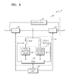
- FIG. 8 is a block diagram illustrating a power supply apparatus 8 according to another embodiment of the present invention.
- the power supply apparatus 8 includes a power supply circuit 80, a battery pack 84, and a control unit 87. Also, the power supply apparatus 8 includes an input terminal "in” and an output terminal "out”.
- the power supply circuit 80 includes a bypass circuit 81, a first power conversion unit 82, and a second power conversion unit 83.
- the power supply circuit 80 is substantially the same as the power supply circuit 10 of FIG. 1 where the switching elements are removed.
- the control unit 87 controls the operations of the first and second power conversion units 82 and 83 instead of controlling the ON/OFF of the switching elements and, if necessary, controls the power applied to input terminals of the first and second power conversion units 82 and 83 to be converted to AC or DC and output to output terminals thereof.
- the control unit 87 controls the first power conversion unit 82 to supply a first DC power to the battery 85. Also, when an emergency situation occurs, the control unit 87 controls the second power conversion unit 83 to generate power to be supplied to a load and an operation power of a BMS 86 by using electric energy stored in the battery 85. Also, although it is not illustrated in the drawing, the battery pack 114 may include a temperature sensor for measuring a temperature of the battery 115. Since the other elements are the same as those illustrated in FIG. 1 , detailed descriptions thereof are omitted herein.
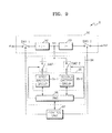
- FIG. 9 is a block diagram illustrating a power supply apparatus 9 according to another embodiment of the present invention.
- the power supply apparatus 9 includes a power supply circuit 90, a battery pack 94, and a control unit 97. Also, the power supply apparatus 9 includes an input terminal "in” and an output terminal "out".
- the power supply circuit 90 includes a first power conversion unit 92, and a second power conversion unit 93.
- the power supply circuit 90 according to the present embodiment is substantially the same as the power supply circuit 10 of FIG. 1 where the bypass circuit 11 is removed.
- the control unit 97 controls the ON/OFF of the switching elements and the operations of the first and second power conversion units 92 and 93 and, if necessary, controls the power applied to input terminals of the first and second power conversion units 92 and 93 to be converted to AC or DC and output to output terminals thereof.
- the control unit 97 controls the first power conversion unit 92 to operate by turning the first switching element SW1-1 on so that a first DC power may be supplied to the battery 95. Also, when an emergency situation occurs, the control unit 97 controls the second power conversion unit 93 to operate by turning the second switching element SW1-2 on so that power to be supplied to a load and an operation power of a BMS 96 may be generated by using electric energy stored in the battery 95. Also, in a normal state, the control unit 97 turns both of the first and second switching elements SW1-1 and SW1-2 on so as to transfer the external power from the input terminal "in” to the output terminal “out” via the first and second power conversion units 92 and 93. Also, although it is not illustrated in the drawing, the battery pack 114 may include a temperature sensor for measuring a temperature of the battery 115. Since the other elements are the same as those illustrated in FIG. 1 , detailed descriptions thereof are omitted herein.
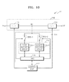
- FIG. 10 is a block diagram illustrating a power supply apparatus 11 according to another embodiment of the present invention.
- the power supply apparatus 11 includes a power supply circuit 110, a battery pack 114, and a control unit 117. Also, the power supply apparatus 11 includes an input terminal "in” and an output terminal "out".
- the power supply circuit 110 includes a first power conversion unit 112, and a second power conversion unit 113.
- the power supply circuit 110 according to the present embodiment is substantially the same as the power supply circuit 80 of FIG. 8 where the bypass circuit 81 is removed.
- the control unit 117 controls the operations of the first and second power conversion units 112 and 113 instead of controlling the ON/OFF of the switching elements and, if necessary, controls the power applied to input terminals of the first and second power conversion units 112 and 113 to be converted to AC or DC and output to output terminals thereof.
- the control unit 117 controls the first power conversion unit 112 to operate so that a first DC power may be supplied to the battery 115. Also, when an emergency situation occurs, the control unit 117 controls the second power conversion unit 113 to operate so that power to be supplied to a load and an operation power of a BMS 116 may be generated by using electric energy stored in the battery 115. Also, in a normal state, the control unit 117 may transfer the external power from the input terminal "in” to the output terminal "out" via the first and second power conversion units 112 and 113. Also, although it is not illustrated in the drawing, the battery pack 114 may include a temperature sensor for measuring a temperature of the battery 115. Since the other elements are the same as those illustrated in FIG. 1 , detailed descriptions thereof are omitted herein.
- a program for executing the controlling methods according to the above-described embodiments and modified examples thereof in the power supply apparatuses 1, 8, 9, and 10 may be stored in a recording medium.
- the recording medium is, for example, a medium that may be read by a processor and a semiconductor recording medium, for example, a flash memory, may be used therefor.
- the medium may be read by a processor and executed by the processor.
Landscapes
- Engineering & Computer Science (AREA)
- Power Engineering (AREA)
- Business, Economics & Management (AREA)
- Emergency Management (AREA)
- Charge And Discharge Circuits For Batteries Or The Like (AREA)
- Stand-By Power Supply Arrangements (AREA)
- Secondary Cells (AREA)
Abstract
Description
- The present invention relates to a power supply apparatus and a controlling method of the same.
- A power supply apparatus is an apparatus for temporarily supplying power to prevent damage to a load or save data the load processes when an abnormal situation occurs in a power source that supplies power to the load and thus a blackout occurs.
- The power supply apparatus includes an internal battery to store electric energy. When an abnormal situation occurs in a power source for supplying power to a load, as described above, the power supply apparatus supplies the electric energy stored in the battery to the load. Also, the power supply apparatus includes a battery controller for controlling the battery to detect a state of the battery or to control charge/discharge operations of the battery.
- The prevent invention provides a power supply apparatus including a plurality of battery groups of batteries and capable of stably supplying power to a load during a blackout or during a particular time period, and a controlling method of the same.
- Accordingly, a power supply apparatus is provided comprising an input terminal adapted to receive an external AC power; an output terminal adapted to output a first AC power, a first power conversion unit adapted to convert the received external AC power to a first DC power and outputs the first DC power; a second power conversion unit adapted to convert a DC power to a first AC power and outputs the first AC power to the output terminal; a first node electrically connected between the output of the first power conversion unit and the input of the second power conversion unit; a control unit adapted to control the operations of the first and second power conversion units; and a first and a second battery group each connected to the control unit and electrically connectable to first node. The first and second battery groups are distinct from each other and can be separately connected to the first node. The control unit is adapted to dynamically allocate one of the first and the second battery group as a first dynamic battery group and the other of the first and the second battery group as a second dynamic battery group depending on a predetermined condition, wherein the first dynamical group acts in a power supply mode, and the second dynamic battery group acts in a standby mode.
- The power supply apparatus may further comprise a bypass circuit electrically connected to the input terminal and the output terminal to bypass the first and second power conversion units.
- The power supply apparatus preferably further comprises a first switching unit connected between the input terminal of the power supply apparatus and the input of the first power conversion unit, and a second switching unit electrically connected between the output of the second power conversion unit and the output terminal of the power supply apparatus, wherein the control unit is adapted to control the operation of the first and second switching elements.
- The power supply apparatus may further comprise a third switching unit electrically connected on one end to the first node and on the other end to the first battery group, and a fourth switching unit electrically connected on one end to the first node and on the other end to the second battery group, wherein the control unit is adapted to control the operation of the third and fourth switching elements such that the first dynamic battery group is connected to the first node and the second dynamic battery group is not connected to the first node.The control unit is preferably adapted to determine a normal operation state, and the predetermined condition corresponds to a first emergency situation, which corresponds to a blackout at the input terminal. The predetermined condition may further correspond to a second emergency situation, which corresponds to the case where a power for a load at the output terminal of the power supply apparatus exceeds the power at the input terminal.
- Upon the determination of an end of the first or second emergency situation, respectively, the control unit is adapted to stop supplying energy of the first dynamic battery group and is adapted to electrically connect the input terminal to the respective first dynamic battery group to recharge the first dynamic battery group.
- In the second emergency situation, the control unit is preferably adapted to control supply of the external AC power to the output terminal of the power supply apparatus in addition to the energy of the first dynamic battery group.
- The control unit may be further adapted to compare a state of charge of the first and second battery groups such that the battery group with higher state of charge is used for power supply.
- The control unit may be further adapted to compare a count or number of use of the first and second battery groups such that the battery group with the lower number or count of use is used for power supply.
- The control unit may be further adapted to compare the temperature of the first and second battery groups such that the battery group with lower temperature is used for power supply.
- The control unit may be further adapted to control supply of the input external AC power to the output of the power supply apparatus in a normal operation state.
- A battery management system may be further provided adapted to control charging and discharging of the first and second battery group, wherein the battery management system is connected to the control unit.
- The power supply apparatus may further comprise a plurality of temperature sensors for measuring the temperature of the first and second battery group.
- The control unit may be further adapted to change assignment of a first or second battery group to the first dynamic battery group if the electric energy stored in the assigned battery group falls below the required energy level.
- As described above, according to the present invention, batteries provided in a power supply apparatus are formed in a plurality of battery groups, and thus, according to the type of emergency, while any one battery group operates in a power supply mode, another battery group operates in a standby mode so that power may be stably supplied to a load.
-
-
FIG. 1 is a block diagram illustrating a power supply apparatus according to an embodiment of the present invention. -
FIGS. 2A to 2C are views illustrating operational states of first and second battery groups according to a change in power. -
FIG. 3 is a block diagram illustrating a power supply apparatus according to another embodiment of the present invention. -
FIG. 4A /B is a flowchart showing a method of controlling a power supply apparatus, according to an embodiment of the present invention. -
FIG. 5 is a flowchart showing a method of controlling a power supply apparatus, according to another embodiment of the present invention. -
FIG. 6 is a flowchart showing a method of controlling a power supply apparatus, according to another embodiment of the present invention. -
FIG. 7 is a flowchart showing a method of controlling a power supply apparatus, according to another embodiment of the present invention. -
FIG. 8 is a block diagram illustrating a power supply apparatus according to another embodiment of the present invention. -
FIG. 9 is a block diagram illustrating a power supply apparatus according to another embodiment of the present invention. -
FIG. 10 is a block diagram illustrating a power supply apparatus according to another embodiment of the present invention. - The present invention may be variously modified and have a variety of embodiments. The embodiments of the present invention are described below in detail with reference to the accompanying drawings. However, the present invention is not limited thereto and it will be understood that various changes in form and details may be made therein without departing from the spirit and scope of the following claims. In the following description, when detailed descriptions about related well-known functions or structures are determined to make the gist of the present invention unclear, the detailed descriptions will be omitted herein.
- Hereinafter, the present invention will be described in detail by explaining exemplary embodiments of the invention with reference to the attached drawings. Like reference numerals in the drawings denote like elements and repeated descriptions thereof are omitted.
-
FIG. 1 is a block diagram illustrating apower supply apparatus 1 according to an embodiment of the present invention. - Referring to
FIG. 1 , thepower supply apparatus 1 according to the present embodiment includes apower supply circuit 10, abattery pack 14, and acontrol unit 17. Also, thepower supply apparatus 1 includes an input terminal "in" and an output terminal "out". - Power from an external power source is applied to the input terminal "in" to be supplied to a load.
- The output terminal "out" may be connected to the load and outputs an external power to the load. Also, when a blackout is caused by a malfunction of the external power source or an overload is generated as supplied power exceeds a maximum supplied power for a particular time period, the output terminal "out" may use electric energy stored in a
battery 15 to output a first AC power to the load. - The
power supply circuit 10 supplies power for operations of the load and a battery management system (BMS) 16. Thepower supply circuit 10 may include abypass circuit 11, a first switching element SW1-1, a second switching element SW1-2, and a firstpower conversion unit 12, and a secondpower conversion unit 13. - The
bypass circuit 11 is connected between the input terminal "in" and the output terminal "out" and transfers the external power directly to the output terminal "out" without conversion. - The first switching element SW1-1 is controlled to supply the external power applied from the input terminal "in" to the first
power conversion unit 12. The first switching element SW1-1 in an ON state supplies the external power to the firstpower conversion unit 12. The first switching element SW1-1 in an OFF state stops the supply of the external power to the firstpower conversion unit 12. The ON/OFF operations of the first switching element SW1-1 may be controlled by thecontrol unit 17. - The first
power conversion unit 12 is connected between the first switching element SW1-1 and a first node N1, and converts received external power to a first DC power and outputs the first DC power to the first node N1. In other words, the firstpower conversion unit 12 may be a rectifier or a converter for converting AC to DC. During the conversion to the first DC power, the firstpower conversion unit 12 makes a voltage that may be used for charging thebattery 15. - The second
power conversion unit 13 is connected between the first node N1 and the second switching element SW1-2. The secondpower conversion unit 13 converts the DC power from the firstpower conversion unit 12 or the electric energy stored in thebattery 15 to a first AC power and outputs the first AC power. In other words, the secondpower conversion unit 13 may be an inverter for converting DC to AC. During the conversion to the first AC power, the secondpower conversion unit 13 makes a voltage that may be used by the load. Alternatively, the secondpower conversion unit 13 may make a feature, such as an amplitude or phase, of the first AC power that is output substantially the same as that of the external power. - The second switching element SW1-2 controls so that the first AC power output from the second
power conversion unit 13 is supplied to the output terminal "out". The second switching element SW1-2 in an ON state supplies the first AC power to the output terminal "out". The second switching element SW1-2 in an OFF state stops the supply of the first AC power to the output terminal "out". The ON/OFF operations of the second switching element SW1-2 may be controlled by thecontrol unit 17. - The
battery pack 14 stores electric energy and supplies the electric energy to the load for emergency situations. In the present invention, an emergency situation may be divided into a first emergency situation and a second emergency situation. The first emergency situation is a case in which a blackout is caused by a malfunction of the external power source. The second emergency situation is a case when a load power exceeds a supplied power due to an abrupt change in the load for a particular time period. The particular time period may be a time period between noon to 2 p.m. in the summer season and a time period between 10 p.m. to midnight in the winter season, or a time period between July to August in the summer season and a time period between December to February in the winter season. The particular time period is not limited to the above examples. - The
battery pack 14 includes thebattery 15, theBMS 16, a third switching element SW2-1, and a fourth switching element SW2-2. - The
battery 15 is a rechargeable secondary battery. Thebattery 15 may be formed by serially and/or parallelly connecting a plurality of battery cells, or by serially and/or parallelly connecting battery modules, each battery module including a plurality of battery cells. Since thebattery 15 supplies electric energy to the load when an emergency situation occurs, a battery cell exhibiting a large capacity characteristic may be used as the battery cell. Thebattery 15 may include at least one battery cell. Thebattery 15 may be a rechargeable secondary battery such as a nickel-cadmium battery, a nickel metal hydride (NiMH) battery, a lithium ion battery, and a lithium polymer battery. - In the present invention, the
battery 15 may be used by being divided into a first battery group 15-1 and a second battery group 15-2. The first battery group 15-1 may include at least one battery and the second battery group 15-2 may include at least one battery. Also, when N-number of batteries exist, at least one battery may be selected as the first battery group 15-1 and the other batteries may be selected as the second battery group 15-2. The first battery group 15-1 and the second battery group 15-2 may operate in different modes according to an emergency situation. - Also, in the present invention, the
battery 15 may be defined as a first dynamic battery group and a second dynamic battery group. The first dynamic battery group is defined as the first battery group 15-1 or the second battery group 15-2 operating in the power supply mode and the second dynamic battery group is defined as the first battery group 15-1 or the second battery group 15-2 operating in the standby mode. - The
control unit 17 may assign thebattery 15 to one of the first and second dynamic battery groups variously according to a type of an emergency situation, a state of charge (SOC) of a battery, a frequency that a battery group operates in the power supply mode, or a temperature of a battery. Also, thecontrol unit 17 may change assignment of the first or second dynamic battery group during the operation of thepower supply apparatus 1. - For example, when the first emergency situation occurs, the first battery group 15-1 may be assigned to a first dynamic battery group to operate in a power supply mode and the second battery group 15-2 may be assigned to a second dynamic battery group to operate in a standby mode. Under the first emergency situation, the first battery group 15-1 may supply the stored electric energy to the load. When the first emergency situation is finished, the first battery group 15-1 is recharged with electric energy.
- Also, when the second emergency situation occurs, the second battery group 15-2 may be assigned to the first dynamic battery group to operate in the power supply mode and the first battery group 15-1 may be assigned to the second dynamic battery group to operate in the standby mode. Under the second emergency situation, the second battery group 15-2 may supply the stored electric energy to the load. Alternatively, under the second emergency situation, the external power from the input terminal "in" may be transferred to the output terminal "out" via the
bypass circuit 11 and simultaneously the electric energy stored in the second battery group 15-2 may be supplied to the load. When the second emergency situation is finished, the second battery group 15-2 is recharged with electric energy. - For another example, when a first emergency situation and a second emergency situation are set to be a first cycle, the operation of the
battery group 15 in the first cycle and in a second cycle is as follows. - When the first emergency situation of the first cycle occurs, the first battery group 15-1 may be assigned to the first dynamic battery group and the second battery group 15-2 may be assigned to the second dynamic battery group. When the second emergency situation of the first cycle occurs, the second battery group 15-2 may be assigned to the first dynamic battery group and the first battery group 15-1 may be assigned to the second dynamic battery group.
- When the first or second emergency situation corresponding to the second cycle occurs during which the
power supply apparatus 1 normally operates after the emergency situation of the first cycle is finished, if the first emergency situation of the second cycle occurs, the second battery group 15-2 may be assigned to the first dynamic battery group and the first battery group 15-1 may be assigned to the second dynamic battery group. Also, if the second emergency situation of the second cycle occurs, the first battery group 15-1 may be assigned to the first dynamic battery group and the second battery group 15-2 may be assigned to the second battery group 15-2. - Also, when the supply amount of the electric energy stored in the first battery group 15-1 or the second battery group 15-2 assigned to the first dynamic battery group under an emergency situation is insufficient, the electric energy stored in the second battery group 15-2 or the first battery group 15-1 operating in the standby mode may be supplied instead to the load. In one embodiment, while the electric energy stored in the second battery group 15-2 is supplied to the load, the first battery group 15-1 may be recharged.
- While the electric energy stored in the first battery group 15-1 or the second battery group 15-2 assigned to the first dynamic battery group is supplied to the load, the second battery group 15-2 or the first battery group 15-1 assigned to the second dynamic battery group may be recharged.
-
FIGS. 2A to 2C are views illustrating operational states of thepower supply apparatus 1 according to a change in power, including the first and second cycles, in whichFIG. 2A illustrates a supplied power and a load power,FIG. 2B illustrates an operational state of the first battery group 15-1 under an emergency situation, andFIG. 2C illustrates an operational state of the second battery group 15-2 under an emergency situation. AlthoughFIGS. 2A to 2C illustrates that a first emergency situation first occurs in the first and second cycles and a second emergency situation occurs later, the present invention is not limited thereto so that the second emergency situation may first occur and the second emergency situation may occur later. Also, the same emergency situation may occur in a plurality of times in the same single cycle. - First, the operations of the first battery group 15-1 and the second battery group 15-2 when the first or second emergency situation of the first cycle occurs are described below.
- When the first emergency situation of the first cycle occurs, the first battery group 15-1 assigned to the first dynamic battery group operates in the power supply mode and the second battery group 15-2 assigned to the second dynamic battery group operates in the standby mode. In
FIG. 2B , asection 201 of the first battery group 15-1 is a section in which a blackout occurs and thepower supply apparatus 1 is returned to a normal state. Thesection 201 may be divided into a section 201-1 and a section 201-2. The section 201-1 is a section in which a blackout actually occurs and the section 201-2 is a section in which the blackout is finished and thepower supply apparatus 1 is returned to a normal state. InFIG. 2B , the supply of power by the first battery group 15-1 may not be finished instantly when the section 201-1 ends, and may be gradually decreased until thepower supply apparatus 1 is returned to a normal state or maintained for a predetermined time, in the section 201-2.When the second emergency situation of the first cycle occurs, the second battery group 15-2 assigned to the first dynamic battery group operates in the power supply mode and the first battery group 15-1 assigned to the second dynamic battery group operates in the standby mode. InFIG. 2C , asection 202 of the second battery group 15-2 is a section in which the power needed for a load in the second emergency situation is returned to a normal state and thus thepower supply apparatus 1 operates in the normal state. Thesection 202 may be divided into a section 202-1 and a section 202-2. The section 202-1 is a section from a time point when a blackout is caused because the load power exceeds the supplied power due to an abrupt change in the load in a particular time period to a time point when the load power is returned to a normal state. In this case, a time point of thesection 202, that is, a time point when the second emergency situation occurs, may be a time point when the supplied power matches the load power as illustrated inFIG. 2A or a time point before the time point when the supplied power matches the load power. The section 202-2 is a section in which thepower supply apparatus 1 is returned to the normal state after the load power is returned to the normal state. InFIG. 2C , the supply of power by the second battery group 15-2 may not be finished instantly when the section 202-1 ends, and may be gradually decreased until thepower supply apparatus 1 is returned to the normal state or maintained for a predetermined time, in the section 202-2. - Next, the operations of the first and second battery groups 15-1 and 15-2 when the first or second emergency situation of the second cycle occurs are described below.
- Unlike the first cycle, when the first emergency situation of the second cycle occurs, the second battery group 15-2 assigned to the first dynamic battery group operates in the power supply mode and the first battery group 15-1 assigned to the second dynamic battery group operates in the standby mode. Also, when the second emergency situation of the second cycle occurs, the first battery group 15-1 assigned to the first dynamic battery group operates in the power supply mode and the second battery group 15-2 assigned to the second dynamic battery group operates in the standby mode.
- The reason for switching the assignment of the first and second dynamic battery groups when the emergency situations of the first and second cycles occur is to prevent imbalance in the battery groups caused by the continuous operation of any one battery group in the power supply mode or the standby mode. In another embodiment, the assignment of the first and second battery groups may be determined based o the following standard.
- When the first or second emergency situation occurs, states of charge (SOC) stored in the first and second battery groups 15-1 and 15-2 are compared with each other. According to a result of the comparison, any one of the first and second battery groups 15-1 and 15-2 having a larger SOC may be assigned to the first dynamic battery group and one having a smaller SOC may be assigned to the second dynamic battery group. When the SOCs of the first and second battery groups 15-1 and 15-2 are the same, as described above, the assignment of the first and second dynamic battery groups may be determined according to the type of an emergency situation. The measurement and comparison of the SOCs of the first and second battery groups 15-1 and 15-2 are performed by the
BMS 16 that is described later. - Also, when the first or second emergency situation occurs, the frequencies that the first and second battery groups 15-1 and 15-2 operate as the first dynamic battery group during a previous emergency situation are determined. Then, any one of the first and second battery groups 15-1 and 15-2 having a less frequency of operating as the first dynamic battery group may be assigned to the first dynamic battery group, whereas the other battery group may be assigned to the second dynamic battery group.
- Also, when the first or second emergency situation occurs, a current temperature and a reference temperature of the first and second battery groups 15-1 and 15-2 are compared with each other. Then, any one of the first and second battery groups 15-1 and 15-2 having a lower temperature may be assigned to the first dynamic battery group, whereas the other battery group may be assigned to the second dynamic battery group. In order to measure the temperatures of the first and second battery groups 15-1 and 15-2, a first temperature sensor 18-1 and a second temperature sensor 18-2 may be included as illustrated in
FIG. 3 . The first and second temperature sensors 18-1 and 18-2 may be thermistors, but not limited thereto. - The third switching element SW2-1 connected between the first node N1 and the first battery group 15-1 may store electric energy in the first battery group 15-1 or output electric energy from the first battery group 15-1. The third switching element SW2-1 is in an ON state under the first emergency situation and supplies the electric energy stored in the first battery group 15-1 to the second
power conversion unit 13. After the first emergency situation is finished, the third switching element SW2-1 may be switched to an OFF state and then switched back to the ON state. When the third switching element SW2-1 is switched back to the ON state, the first battery group 15-1 may be recharged with the first DC power from the firstpower conversion unit 12. The ON/OFF operations of the third switching element SW2-1 may be controlled by theBMS 16. - The fourth switching element SW2-2 connected between the first node N1 and the second battery group 15-2 may store electric energy in the second battery group 15-2 or output electric energy from the second battery group 15-2. The fourth switching element SW2-2 is exemplarily in an ON state under the second emergency situation and supplies the electric energy stored in the second battery group 15-2 to the second
power conversion unit 13. After the second emergency situation is finished, the fourth switching element SW2-2 is in an ON state so that the first battery group 15-1 may be recharged with the first DC power from the firstpower conversion unit 12. The ON/OFF operations of the fourth switching element SW2-2 may be controlled by theBMS 16. - The
BMS 16 controls charge and discharge of thebattery 15. In other words, theBMS 16 operates as a protection circuit. TheBMS 16 may include an analog front end (AFE) (not shown) for sensing a voltage, a current, and a temperature of thebattery 15, and a microcomputer (not shown) for controlling an operation of the AFE and transferring data to thecontrol unit 17 or an external monitoring apparatus (not shown). TheBMS 16 performs a sensing operation and a communication operation not only when thebattery 15 performs a charge or discharge operation but also in a normal state. - Also, the
BMS 16 outputs a switching control signal for switching the third switching element SW2-1 or the fourth switching element SW2-2 according to the type of emergency situation. As described above, when receiving generation of the first emergency situation from thecontrol unit 17, theBMS 16 may output a control signal to turn the third switching element SW2-1 on. When receiving generation of the second emergency situation from thecontrol unit 17, theBMS 16 may output a control signal to turn the fourth switching element SW2-2 on. Also, when receiving termination of the first or second emergency situation from thecontrol unit 17, theBMS 16 may turn the third or fourth switching element SW2-1 or SW2-2 on to charge the first or second battery group 15-1 or 15-2. - Furthermore, in the present embodiment, the
BMS 16 may output a switching control signal for switching the third or fourth switching element SW2-1 or SW2-2 by measuring and comparing the SOCs of the first and second battery groups 15-1 and 15-2, measuring the frequency of operations as the first dynamic battery group in a previous emergency situation, or comparing the measured temperatures of the first and second battery groups 15-1 and 15-2 with each other. TheBMS 16 may simultaneously turn the third and fourth switching elements SW2-1 and SW2-2 on or off, or turn one switching element on while turning the other switching element off. - The
control unit 17 controls an operation of each of the elements of thepower supply apparatus 1. Thecontroller 17 controls the ON/OFF operations of the first and second switching elements SW1-1 and SW1-2. In detail, when the remaining amount of thebattery 15 is small, thecontrol unit 17 supplies electric power by turning the first switching element SW1-1 on to charge thebattery 15. When an emergency situation occurs, thecontrol unit 17 turns the second switching element SW1-2 on so that the electric energy stored in thebattery 15 may be supplied to the load. - The
control unit 17 senses an abnormal state of the external power source and, when an emergency situation occurs, controls thepower supply apparatus 1 to operate as an uninterruptible power supply (UPS). In other words, thecontrol unit 17 controls the external power to be transferred to the load in a normal state in which the external power source supplies electric power to the load, and controls thepower supply circuit 10 to generate an operation power of theBMS 16 by using the external power. Also, when a blackout is caused by a malfunction of the external power source or an overload is generated as supplied power exceeds a maximum supplied power for a particular time period, thecontrol unit 17 controls thepower supply circuit 10 to generate electric power to be supplied to the load and the operation power of theBMS 16 by using the electric energy stored in thebattery 15. - A method of supplying an operation power of the
BMS 16 in thepower supply apparatus 1 according to the present embodiment is described below. -
FIG. 4A /B is a flowchart showing a method of controlling thepower supply apparatus 1, according to an embodiment of the present invention. - Referring to
FIG. 4A /B, thecontrol unit 17 selects at least one of a plurality batteries as the first battery group 15-1 and the other batteries as the second battery group 15-2, and then assigns the first dynamic battery group to operate in the power supply mode and the second dynamic battery group to operate in the standby mode (S401). - When the assignment of the first and second dynamic battery groups is completed, the
control unit 17 may determine whether the first emergency situation occurs in which a blackout is caused due to the malfunction of the external power or overload (S403). - When the first emergency situation occurs, the
control unit 17 turns the first switching element SW1-1 off and the second switching element SW1-2 on (S405). When the first switching element SW1-1 is turned off and the second switching element SW1-2 is turned on, the electric energy stored in thebattery 15 is output to the output terminal "out" via the secondpower conversion unit 13. Also, thecontrol unit 17 controls theBMS 16 to operate thebattery 15 in the power supply mode and the standby mode. - When the first emergency situation occurs, the
BMS 16 under the control of thecontrol unit 17 turns the third switching element SW2-1 on and the fourth switching element SW2-2 off so that the first battery group 15-1 or the second battery group 15-2 assigned to the first dynamic battery group may supply power and the first battery group 15-1 or the second battery group 15-2 assigned to the second dynamic battery group may operate in the standby mode (S407). For example, when the first battery group 15-1 is assigned to the first dynamic battery group, the electric energy stored in the first battery group 15-1 is converted to the first AC power by the secondpower conversion unit 13 and then is output to the output terminal "out". - Then, the
control unit 17 determines whether the first emergency situation is finished (S409). In other words, thecontrol unit 17 determines whether the external power source is in a normal state and is switched to a state of supplying the external power to the load or normally supplying the load power. - When the first emergency situation is finished, the
control unit 17 transfers the external power from the input terminal "in" to the output terminal "out" via the bypass circuit 11 (S411). - Thereafter, the
control unit 17 turns the first switching element SW1-1 on and the second switching element SW1-2 off (S413). When the first switching element SW1-1 is turned on and the second switching element SW1-2 is turned off, the external power from the input terminal "in" is converted to the first DC power by the firstpower conversion unit 12 and then is used to recharge the first battery group 15-1. In this state, the third switching element SW2-1 is turned on. - In the present embodiment, operations S411 and S413 may be simultaneously performed. In other words, when the first emergency situation is finished, the external power from the input terminal "in" is transferred to the output terminal "out" via the
bypass circuit 11, and simultaneously, thepower supply apparatus 1 is returned to a normal state. In this state, thecontrol unit 17 turns the first switching element SW1-1 on and the second switching element SW1-2 off so that the external power from the input terminal "in" is converted to the first DC power by the firstpower conversion unit 12. Accordingly, the first battery group 15-1 or the second battery group 15-2 assigned to the first dynamic battery group may be recharged with the first DC power. - When the external power source is in a normal state and the external power is supplied to the load, the
control unit 17 determines whether the second emergency situation occurs, which is a case just before a blackout is caused because a load power exceeds a supplied power due to an abrupt change in the load in a particular time period (S415). - When the first and second emergency situations do not occur, the
control unit 17 transfers the external power from the input terminal "in" to the output terminal "out" via the bypass circuit 11 (S417). - However, when the second emergency situation occurs, the
control unit 17 turns the first switching element SW1-1 off and the second switching element SW1-2 on (S419). When the first switching element SW1-1 is turned off and the second switching element SW1-2 is turned on, the electric energy stored in thebattery 15 is output to the output terminal "out" via the secondpower conversion unit 13. Also, thecontrol unit 17 controls theBMS 16 to operate the battery groups in the power supply mode and the standby mode. - When the second emergency situation occurs, the
BMS 16 under the control of thecontrol unit 17 turns the third switching element SW2-1 off and the fourth switching element SW2-2 on so that the first battery group 15-1 or the second battery group 15-2 assigned to the first dynamic battery group may supply power and the first battery group 15-1 or the second battery group 15-2 assigned to the second dynamic battery group may operate in the standby mode while the external power from the input terminal "in" may be transferred to the output terminal "out" via the bypass circuit 11 (S421). For example, when the second battery group 15-2 is assigned to the first dynamic battery group, the electric energy stored in the second battery group 15-2 is converted to the first AC power by the secondpower conversion unit 13 and then is output to the output terminal "out" and simultaneously the external power from the input terminal "in" may be output to the output terminal "out" via thebypass circuit 11. - Then, the
control unit 17 determines whether the second emergency situation is finished (S423). In other words, thecontrol unit 17 determines whether the external power source is in a normal state and is switched to a state of supplying the external power to the load. - When the second emergency situation is finished, the
control unit 17 turns the first switching element SW1-1 and the second switching element SW1-2 off, transfers the external power from the input terminal "in" to the output terminal "out" via thebypass circuit 11, and then, turns the first switching element SW1-1 on and the second switching element SW1-2 off. Accordingly, operations S411 and S413 in which the second battery group 15-2 is recharged are performed. Also, operations S411 and S413 may be simultaneously performed. Since the subsequent processes have already been described above, detailed descriptions thereof are omitted herein. -
FIG. 5 is a flowchart showing a method of controlling thepower supply apparatus 1, according to another embodiment of the present invention. - Referring to
FIG. 5 , thecontrol unit 17 determines whether the first or second emergency situation occurs (S501). - When the first or second emergency situation does not occur, the
control unit 17 transfers the external power from the input terminal "in" to the output terminal "out" via the bypass circuit 11 (S503). When the first or second emergency situation occurs, thecontrol unit 17 turns the first switching element SW1-1 off and the second switching element SW1-2 on (S505). When the first switching element SW1-1 is turned off and the second switching element SW1-2 is turned on, the electric energy stored in thebattery 15 is output to the output terminal "out" via the secondpower conversion unit 13. Also, thecontrol unit 17 controls theBMS 16 to operate the battery groups in the power supply mode and the standby mode. - When the first or second emergency situation occurs, the
BMS 16 under the control of thecontrol unit 17 checks and compares the SOCs of the first and second battery groups 15-1 and 15-2 with each other (S507). - The controller receiving a result of the comparison from the
BMS 16 assigns any one of the first and second battery groups 15-1 and 15-2 having a larger SOC to the first dynamic battery group to supply power and one having a smaller SOC to the second dynamic battery group to operate in the standby mode (S509). The third or fourth switching element SW2-1 or SW2-2 to operate in the power supply mode is turned on. The electric energy stored in the first or second battery group 15-1 or 15-2 assigned to the first dynamic battery group is converted to the first AC power by the secondpower conversion unit 13 and is output to the output terminal "out". As a result of the comparison, when the SOCs of the first and second battery groups 15-1 and 15-2 are the same, as illustrated inFIG. 3 , any one of the first and second dynamic battery groups 15-1 and 15-2 may be assigned to the first dynamic battery group according to the type of an emergency situation. - Then, the
control unit 17 determines whether the first or second emergency situation is finished (S511). In other words, thecontrol unit 17 determines whether the external power source is in a normal state and the external power is supplied to the load. - When the first or second emergency situation is finished, the
control unit 17 transfers the external power from the input unit "in" to the output terminal "out" via the bypass circuit 11 (S513). - After transferring the external power from the input unit "in" to the output terminal "out" via the
bypass circuit 11, thecontrol unit 17 turns the first switching element SW1-1 on and the second switching element SW1-2 off (S515). When the first switching element SW1-1 is turned on and the second switching element SW1-2 is turned off, the external power from the input unit "in" is converted to the first DC power by the firstpower conversion unit 12 and is used to recharge the first or second battery group 15-1 or 15-2 operating as the first dynamic battery group. - In the present embodiment, operations S513 and S515 may be simultaneously performed. In other words, when the emergency situation is finished, the
power supply apparatus 1 is returned to a normal state. In this state, thecontrol unit 17 transfers the external power from the input unit "in" to the output terminal "out" via thebypass circuit 11, and simultaneously, turns the first switching element SW1-1 on and the second switching element SW1-2 off, so that the external power from the input terminal "in" may be converted to the first DC power by the firstpower conversion unit 12 and then used to recharge the battery group operating in the power supply mode. -
FIG. 6 is a flowchart showing a method of controlling thepower supply apparatus 1, according to another embodiment of the present invention. - Referring to
FIG. 6 , thecontrol unit 17 determines whether the first or second emergency situation occurs (S601). - When the first or second emergency situation does not occur, the
control unit 17 transfers the external power from the input terminal "in" to the output terminal "out" via the bypass circuit 11 (S603). - However, when the first or second emergency situation occurs, the
control unit 17 turns the first switching element SW1-1 off and the second switching element SW1-2 on (S605). When the first switching element SW1-1 is turned off and the second switching element SW1-2 is turned on, the electric energy stored in thebattery 15 is output to the output terminal "out" via the secondpower conversion unit 13. Also, thecontrol unit 17 controls theBMS 16 to operate the battery groups in the power supply mode and the standby mode. - When the first or second emergency situation occurs, the
BMS 16 under the control of thecontrol unit 17 compares the frequencies that the first and second battery groups 15-1 and 15-2 operate as the first dynamic battery group during a previous emergency situation (S607). The frequencies may be determined by the number or count of use of a specific battery group 15-1 or 15-2 as a first or second dynamic battery group. - The
control unit 17 assigns any one of the first and second battery groups 15-1 and 15-2 having a lower frequency of operating as the first dynamic battery group during a previous emergency situation to the first dynamic battery group to supply power and one having a higher frequency of operating as the first dynamic battery group to the second dynamic battery group to operate in the standby mode(S609). The third or fourth switching element SW2-1 or SW2-2 to operate in the power supply mode is turned on. When the frequencies that the first and second battery groups 15-1 and 15-2 operate as the first dynamic battery group during a previous emergency situation are the same as a result of the comparison, as illustrated inFIG. 3 , any one of the first and second battery groups 15-1 and 15-2 may be assigned to the first dynamic battery group according to the type of an emergency situation. The electric energy stored in the first or second battery group 15-1 or 15-2 assigned to the first dynamic battery group is converted to the first AC power by the secondpower conversion unit 13 and is output to the output terminal "out". - Then, the
control unit 17 determines whether the first or second emergency situation is finished (S611). In other words, thecontrol unit 17 determines whether the external power source is in a normal state and the external power is supplied to the load. - When the first or second emergency situation is finished, the
control unit 17 transfers the external power from the input unit "in" to the output terminal "out" via the bypass circuit 11 (S613). - After transferring the external power from the input unit "in" to the output terminal "out" via the
bypass circuit 11, thecontrol unit 17 turns the first switching element SW1-1 on and the second switching element SW1-2 off (S615). When the first switching element SW1-1 is turned on and the second switching element SW1-2 is turned off, the external power from the input unit "in" is converted to the first DC power by the firstpower conversion unit 12 and is used to recharge the battery group operating in the power supply mode. - In the present embodiment, operations S613 and S615 may be simultaneously performed. In other words, when the emergency situation is finished, the
power supply apparatus 1 is returned to a normal state. In this state, thecontrol unit 17 transfers the external power from the input unit "in" to the output terminal "out" via thebypass circuit 11, and simultaneously, turns the first switching element SW1-1 on and the second switching element SW1-2 off, so that the external power from the input terminal "in" may be converted to the first DC power by the firstpower conversion unit 12 and then used to recharge the battery group operating in the power supply mode. -
FIG. 7 is a flowchart showing a method of controlling thepower supply apparatus 1, according to another embodiment of the present invention. - Referring to
FIG. 7 , thecontrol unit 17 determines whether the first or second emergency situation occurs (S701). - When the first or second emergency situation does not occur, the
control unit 17 transfers the external power from the input terminal "in" to the output terminal "out" via the bypass circuit 11 (S703). - However, when the first or second emergency situation occurs, the
control unit 17 turns the first switching element SW1-1 off and the second switching element SW1-2 on (S705). - When the first switching element SW1-1 is turned off and the second switching element SW1-2 is turned on, the electric energy stored in the
battery 15 is output to the output terminal "out" via the secondpower conversion unit 13. Also, thecontrol unit 17 controls theBMS 16 to operate the battery groups in the power supply mode and the standby mode. - When the first or second emergency situation occurs, the
BMS 16 under the control of thecontrol unit 17 compares the temperatures of the first and second battery groups 15-1 and 15-2 (S707). - The
control unit 17 receiving a result of the comparison from theBMS 16 assigns any one of the first and second battery groups 15-1 and 15-2 having a lower temperature to the first dynamic battery group to supply power and one having a higher temperature to the second dynamic battery group to operate in the standby mode (S709). The third or fourth switching element SW2-1 or SW2-2 to operate in the power supply mode is turned on. When the temperatures of the first and second battery groups 15-1 and 15-2 are the same as a result of the comparison, as illustrated inFIG. 3 , any one of the first and second battery groups 15-1 and 15-2 may be assigned to the first dynamic battery group according to the type of an emergency situation. The electric energy stored in the first or second battery group 15-1 or 15-2 assigned to the first dynamic battery group is converted to the first AC power by the secondpower conversion unit 13 and is output to the output terminal "out". - Then, the
control unit 17 determines whether the first or second emergency situation is finished (S711). In other words, thecontrol unit 17 determines whether the external power source is in a normal state and the external power is supplied to the load. - When the first or second emergency situation is finished, the
control unit 17 transfers the external power from the input unit "in" to the output terminal "out" via the bypass circuit 11 (S713). - After transferring the external power from the input unit "in" to the output terminal "out" via the
bypass circuit 11, thecontrol unit 17 turns the first switching element SW1-1 on and the second switching element SW1-2 off (S715). When the first switching element SW1-1 is turned on and the second switching element SW1-2 is turned off, the external power from the input unit "in" is converted to the first DC power by the firstpower conversion unit 12 and is used to recharge the battery group 15-1 operating in the power supply mode. - In the present embodiment, operations S713 and S715 may be simultaneously performed. In other words, when the emergency situation is finished, the
power supply apparatus 1 is returned to a normal state. In this state, thecontrol unit 17 transfers the external power from the input unit "in" to the output terminal "out" via thebypass circuit 11, and simultaneously, turns the first switching element SW1-1 on and the second switching element SW1-2 off, so that the external power from the input terminal "in" may be converted to the first DC power by the firstpower conversion unit 12 and then used to recharge the battery group operating in the power supply mode. -
FIG. 8 is a block diagram illustrating apower supply apparatus 8 according to another embodiment of the present invention. - Referring to
FIG. 8 , thepower supply apparatus 8 according to the present embodiment includes apower supply circuit 80, abattery pack 84, and acontrol unit 87. Also, thepower supply apparatus 8 includes an input terminal "in" and an output terminal "out". - The
power supply circuit 80 according to the present embodiment includes abypass circuit 81, a firstpower conversion unit 82, and a secondpower conversion unit 83. In other words, thepower supply circuit 80 is substantially the same as thepower supply circuit 10 ofFIG. 1 where the switching elements are removed. Thecontrol unit 87 controls the operations of the first and secondpower conversion units power conversion units - When a
battery 85 needs to be recharged due to an insufficient remaining capacity, thecontrol unit 87 controls the firstpower conversion unit 82 to supply a first DC power to thebattery 85. Also, when an emergency situation occurs, thecontrol unit 87 controls the secondpower conversion unit 83 to generate power to be supplied to a load and an operation power of aBMS 86 by using electric energy stored in thebattery 85. Also, although it is not illustrated in the drawing, thebattery pack 114 may include a temperature sensor for measuring a temperature of thebattery 115. Since the other elements are the same as those illustrated inFIG. 1 , detailed descriptions thereof are omitted herein. -
FIG. 9 is a block diagram illustrating a power supply apparatus 9 according to another embodiment of the present invention. - Referring to FIG. 99, the power supply apparatus 9 according to the present embodiment includes a
power supply circuit 90, abattery pack 94, and acontrol unit 97. Also, the power supply apparatus 9 includes an input terminal "in" and an output terminal "out". - The
power supply circuit 90 according to the present embodiment includes a firstpower conversion unit 92, and a secondpower conversion unit 93. In other words, thepower supply circuit 90 according to the present embodiment is substantially the same as thepower supply circuit 10 ofFIG. 1 where thebypass circuit 11 is removed. Thecontrol unit 97 controls the ON/OFF of the switching elements and the operations of the first and secondpower conversion units power conversion units - When a
battery 95 needs to be recharged due to an insufficient remaining capacity, thecontrol unit 97 controls the firstpower conversion unit 92 to operate by turning the first switching element SW1-1 on so that a first DC power may be supplied to thebattery 95. Also, when an emergency situation occurs, thecontrol unit 97 controls the secondpower conversion unit 93 to operate by turning the second switching element SW1-2 on so that power to be supplied to a load and an operation power of aBMS 96 may be generated by using electric energy stored in thebattery 95. Also, in a normal state, thecontrol unit 97 turns both of the first and second switching elements SW1-1 and SW1-2 on so as to transfer the external power from the input terminal "in" to the output terminal "out" via the first and secondpower conversion units battery pack 114 may include a temperature sensor for measuring a temperature of thebattery 115. Since the other elements are the same as those illustrated inFIG. 1 , detailed descriptions thereof are omitted herein. -
FIG. 10 is a block diagram illustrating apower supply apparatus 11 according to another embodiment of the present invention. - Referring to
FIG. 10 , thepower supply apparatus 11 according to the present embodiment includes apower supply circuit 110, abattery pack 114, and acontrol unit 117. Also, thepower supply apparatus 11 includes an input terminal "in" and an output terminal "out". - The
power supply circuit 110 according to the present embodiment includes a firstpower conversion unit 112, and a secondpower conversion unit 113. In other words, thepower supply circuit 110 according to the present embodiment is substantially the same as thepower supply circuit 80 ofFIG. 8 where thebypass circuit 81 is removed. Thecontrol unit 117 controls the operations of the first and secondpower conversion units power conversion units - When a
battery 115 needs to be recharged due to an insufficient remaining capacity, thecontrol unit 117 controls the firstpower conversion unit 112 to operate so that a first DC power may be supplied to thebattery 115. Also, when an emergency situation occurs, thecontrol unit 117 controls the secondpower conversion unit 113 to operate so that power to be supplied to a load and an operation power of aBMS 116 may be generated by using electric energy stored in thebattery 115. Also, in a normal state, thecontrol unit 117 may transfer the external power from the input terminal "in" to the output terminal "out" via the first and secondpower conversion units battery pack 114 may include a temperature sensor for measuring a temperature of thebattery 115. Since the other elements are the same as those illustrated inFIG. 1 , detailed descriptions thereof are omitted herein. - A program for executing the controlling methods according to the above-described embodiments and modified examples thereof in the
power supply apparatuses - While this invention has been particularly shown and described with reference to preferred embodiments thereof, it will be understood by those skilled in the art that various changes in form and details may be made therein without departing from the spirit and scope of the invention as defined by the appended claims. The preferred embodiments should be considered in descriptive sense only and not for purposes of limitation. Therefore, the scope of the invention is defined not by the detailed description of the invention but by the appended claims, and all differences within the scope will be construed as being included in the present invention.
- All documents including a published document, a patent application, a patent, etc. that are cited in the present application may be combined in the present invention in the same way as one that each cited document indicates individually and in combination with the present invention in detail or one that the cited documents indicate in combination with the present invention as a whole.
Claims (15)
- A power supply apparatus (1) comprising:an input terminal (IN) adapted to receive an external AC power;an output terminal (OUT) adapted to output a first AC power,a first power conversion unit (12) adapted to convert the received external AC power to a first DC power and outputs the first DC power;a second power conversion unit (13) adapted to convert a DC power to a first AC power and outputs the first AC power to the output terminal (OUT);a first node (N1) electrically connected between the output of the first power conversion unit (12) and the input of the second power conversion unit (13);a control unit (17) adapted to control the operations of the first and second power conversion units (12, 13); anda first and a second battery group (15-1, 15-2) each connected to the control unit (17) and electrically connectable to first node (N1),wherein the control unit (17) is adapted to dynamically allocate one of the first and the second battery group as a first dynamic battery group and the other of the first and the second battery group as a second dynamic battery group depending on a predetermined condition, whereinthe first dynamical group acts in a power supply mode, andthe second dynamic battery group acts in a standby mode.
- The power supply apparatus (1) according to claim 1, further comprising a bypass circuit (11) electrically connected to the input terminal (IN) and the output terminal (OUT) to bypass the first and second power conversion units (12, 13).
- The power supply apparatus (1) according to claim 1 or 2, further comprising:a first switching unit (SW1-1) connected between the input terminal (IN) of the power supply apparatus (1) and the input of the first power conversion unit (12), anda second switching unit (SW1-2) electrically connected between the output of the second power conversion unit (13) and the output terminal (OUT) of the power supply apparatus,wherein the control unit (17) is adapted to control the operation of the first and second switching elements (SW1-2, SW1-2).
- The power supply apparatus (1) of any of the previous claims, further comprising:a third switching unit (SW2-1) electrically connected on one end to the first node (N1) and on the other end to the first battery group (15-1), anda fourth switching unit (SW2-2) electrically connected on one end to the first node (N1) and on the other end to the second battery group (15-2),wherein the control unit (17) is adapted to control the operation of the third and fourth switching elements (SW2-1, SW2-2) such that the first dynamic battery group (15-1, 15-2) is connected to the first node (N1) and the second dynamic battery group is not connected to the first node (N1).
- The power supply apparatus (1) of any of the previous claims, wherein the control unit (17) is adapted to determine:a normal operation state, andthe predetermined condition corresponds to a first emergency situation, which corresponds to a blackout at the input terminal (IN).
- The power supply apparatus (1) of any of the previous claims, wherein the predetermined condition corresponds to a second emergency situation, which correspons to the case where a power for a load at the output terminal (OUT) of the power supply apparatus (1) exceeds the power at the input terminal (IN).
- The power supply apparatus (1) of claim 5 or 6, wherein upon the determination of an end of the first or second emergency situation, respectively, the control unit (17) is adapted to stop supplying energy of the first dynamic battery group (15-1, 15-2) and is adapted to electrically connect the input terminal (IN) to the respective first dynamic battery group (15-1, 15-2) to recharge the first dynamic battery group (15-1, 15-2).
- The power supply apparatus (1) of any of the previous claims 6 or 7, wherein in the second emergency situation, the control unit (17) is adapted to control supply of the external AC power to the output terminal (OUT) of the power supply apparatus (1) in addition to the energy of the first dynamic battery group.
- The power supply apparatus (1) of any of claims 7 or 8, wherein the control unit (17) is further adapted to compare a state of charge of the first and second battery groups (15-1, 15-2) such that the battery group (15-1, 15-2) with higher state of charge is used for power supply.
- The power supply apparatus (1) of any of claims 7 or 8, wherein the control unit (17) is further adapted to compare a number or count of use of the first and second battery groups (15-1, 15-2) as the first dynamic battery group such that the battery group (15-1, 15-2) with a lower number of use is used for power supply.
- The power supply apparatus (1) of any of claims 7 or 8, wherein the control unit (17) is further adapted to compare the temperature of the first and second battery groups (15-1, 15-2) such that the battery group (15-1, 15-2) with lower temperature is used for power supply.
- The power supply apparatus (1) of any of claims 5 to 11, wherein the control unit (17) is further adapted to control supply of the input external AC power to the output of the power supply apparatus (1) in a normal operation state.
- The power supply apparatus (1) of any of the previous claims, further comprising a battery management system (16) adapted to control charging and discharging of the first and second battery group (15-1, 15-2), wherein the battery management system (16) is connected to the control unit (17).
- The power supply apparatus (1) of any of the previous claims, further comprising a plurality of temperature sensors for measuring the temperature of the first and second battery group (15-1, 15-2).
- The power supply apparatus (1) of any of the previous claims, wherein the control unit (17) is further adapted to change assignment of a first or second battery group (15-1, 15-2) to the first dynamic battery group if the electric energy stored in the assigned battery group (15-1, 15-2) falls below a required energy level.
Applications Claiming Priority (2)
| Application Number | Priority Date | Filing Date | Title |
|---|---|---|---|
| US201261635207P | 2012-04-18 | 2012-04-18 | |
| US13/597,952 US9231440B2 (en) | 2012-04-18 | 2012-08-29 | Power supply apparatus and controlling method of the same |
Publications (2)
| Publication Number | Publication Date |
|---|---|
| EP2654176A1 true EP2654176A1 (en) | 2013-10-23 |
| EP2654176B1 EP2654176B1 (en) | 2017-01-18 |
Family
ID=47221919
Family Applications (1)
| Application Number | Title | Priority Date | Filing Date |
|---|---|---|---|
| EP12184277.7A Active EP2654176B1 (en) | 2012-04-18 | 2012-09-13 | Power supply apparatus and controlling method of the same |
Country Status (5)
| Country | Link |
|---|---|
| US (1) | US9231440B2 (en) |
| EP (1) | EP2654176B1 (en) |
| JP (1) | JP6192345B2 (en) |
| KR (1) | KR101440889B1 (en) |
| CN (2) | CN103378650A (en) |
Cited By (6)
| Publication number | Priority date | Publication date | Assignee | Title |
|---|---|---|---|---|
| WO2017160298A1 (en) * | 2016-03-17 | 2017-09-21 | Hewlett-Packard Development Company, L.P. | Provide bounded voltage range |
| EP3159997A4 (en) * | 2014-06-03 | 2018-03-21 | Sony Corporation | Electrical power-supplying device and method for supplying electrical power |
| DE102019003232A1 (en) * | 2019-05-03 | 2020-11-05 | Claus Jürgen Gosch | Mobile device for providing energy and a vehicle with such a device and a method for operating a mobile energy supply |
| EP3772154A1 (en) * | 2019-07-31 | 2021-02-03 | ABB Schweiz AG | A power supply system, and an uninterruptible power supply including the power supply system |
| CN112491131A (en) * | 2020-11-23 | 2021-03-12 | 安徽南瑞继远电网技术有限公司 | Mobile emergency power supply system of transformer substation based on metal-air battery |
| CN115579929A (en) * | 2022-11-21 | 2023-01-06 | 成都特隆美储能技术有限公司 | Control method for improving battery protection of energy storage system |
Families Citing this family (46)
| Publication number | Priority date | Publication date | Assignee | Title |
|---|---|---|---|---|
| CN103746446B (en) * | 2013-12-20 | 2016-09-07 | 青岛歌尔声学科技有限公司 | A kind of uninterrupted power supply circuit and electronic product |
| FR3016702B1 (en) * | 2014-01-17 | 2017-08-04 | Blue Solutions | METHOD AND SYSTEM FOR MANAGING A PLURALITY OF ENERGY STORAGE ASSEMBLY |
| TWI645646B (en) * | 2014-01-23 | 2018-12-21 | Gogoro Inc. | Systems and methods for utilizing an array of power storage devices, such as batteries |
| KR101532673B1 (en) * | 2014-03-24 | 2015-07-09 | 재단법인대구경북과학기술원 | Power Supply Apparatus and Method |
| US20150372537A1 (en) * | 2014-06-18 | 2015-12-24 | Emerson Network Power, Energy Systems, North America, Inc. | Systems and methods for preventing electric power converters from operating in sleep mode |
| CN104167783B (en) * | 2014-08-06 | 2017-08-22 | 西安石油大学 | Dc source low ripple implementation method and circuit that a kind of battery last is powered |
| DE102014114792A1 (en) | 2014-10-13 | 2016-04-14 | Thyssenkrupp Ag | Method for operating a power grid, in particular a power grid of a watercraft |
| KR101651022B1 (en) * | 2014-12-15 | 2016-08-25 | 오씨아이 주식회사 | Energy storage system and method for controlling thereof |
| CN104578391A (en) * | 2015-01-21 | 2015-04-29 | 武汉美格科技有限公司 | High-power miniature back-up power |
| CN105990893B (en) * | 2015-02-13 | 2019-07-26 | 中兴通讯股份有限公司 | Method of supplying power to, device and terminal |
| JP6489204B2 (en) | 2015-03-12 | 2019-03-27 | オムロン株式会社 | Battery, system, battery management method, battery management program, and recording medium |
| JP6540792B2 (en) | 2015-03-12 | 2019-07-10 | オムロン株式会社 | System, battery damage degree calculation device, battery management method, battery management program, and recording medium |
| JP6590531B2 (en) * | 2015-05-28 | 2019-10-16 | シャープ株式会社 | Self-propelled electronic device |
| US20170063127A1 (en) * | 2015-08-26 | 2017-03-02 | The Aes Corporation | Battery Backup Capacity Method and System |
| JP6372452B2 (en) * | 2015-09-02 | 2018-08-15 | 東芝三菱電機産業システム株式会社 | Uninterruptible power supply and control method thereof |
| WO2017044122A1 (en) * | 2015-09-11 | 2017-03-16 | Hewlett Packard Enterprise Development Lp | Power distribution with batteries |
| KR102400501B1 (en) * | 2015-09-24 | 2022-05-20 | 삼성에스디아이 주식회사 | Uninterruptible power supply |
| KR102010021B1 (en) * | 2015-11-18 | 2019-08-12 | 주식회사 엘지화학 | Apparatus and method for managing battery pack |
| AU2016355125A1 (en) | 2015-11-20 | 2018-07-05 | David Long | Power manager with reconfigurable power converting circuits |
| US11258366B2 (en) | 2015-11-20 | 2022-02-22 | Galvion Soldier Power, Llc | Power manager with reconfigurable power converting circuits |
| WO2017134124A1 (en) * | 2016-02-02 | 2017-08-10 | Koninklijke Philips N.V. | A multifunctional power distribution apparatus |
| US10635148B2 (en) * | 2016-04-07 | 2020-04-28 | Dell Products L.P. | Information handling system peripheral port power bypass |
| US10374455B2 (en) * | 2016-04-29 | 2019-08-06 | Hewlett Packard Enterprise Development Lp | Uninterruptible power supply including battery modules connected directly to direct current-alternating current inverter |
| US10589633B2 (en) * | 2016-06-28 | 2020-03-17 | Ford Global Technologies, Llc | Fast charging battery system |
| US10992144B2 (en) * | 2017-05-17 | 2021-04-27 | Galley Power LLC | Battery balancing and current control with bypass circuit for load switch |
| CN107046317A (en) * | 2017-05-31 | 2017-08-15 | 无锡华润矽科微电子有限公司 | The management of charging and discharging system of battery |
| KR102042319B1 (en) * | 2017-12-15 | 2019-11-08 | 유준호 | Apparatus and method for selectively supplying wired/wireless power to electric vechile |
| CN108429299B (en) * | 2018-01-24 | 2021-01-01 | 上海广为美线电源电器有限公司 | Dual voltage emergency start power supply with isolated communication automatic conversion technology |
| KR102390394B1 (en) * | 2018-05-15 | 2022-04-22 | 주식회사 엘지에너지솔루션 | Apparatus and method for controlling main battery and sub battery |
| FR3082677B1 (en) | 2018-06-06 | 2021-04-16 | Commissariat Energie Atomique | ELECTRICAL SYSTEM WITH COMMUTED CELLS AND PROCEDURE FOR CONTROLLING SUCH A SYSTEM |
| CN109245218A (en) * | 2018-09-30 | 2019-01-18 | 温良桂 | A kind of new energy central control system |
| TWI685178B (en) * | 2019-01-03 | 2020-02-11 | 台達電子工業股份有限公司 | Power supply system |
| US11327901B2 (en) * | 2019-03-01 | 2022-05-10 | GM Global Technology Operations LLC | Modular dynamically allocated capacity storage systems implemented as respective batteries each having multiple source terminals |
| JP2021035193A (en) * | 2019-08-26 | 2021-03-01 | 株式会社東芝 | Power supply device |
| CN110429705A (en) * | 2019-08-29 | 2019-11-08 | 强文 | A kind of integrated type electrical information interactive device of included UPS |
| CN110690752B (en) * | 2019-10-12 | 2020-12-29 | 东莞市峰谷科技有限公司 | BMS management method for multi-battery pack parallel control |
| CA3167174A1 (en) | 2020-02-06 | 2021-09-23 | Christopher Moore | Rugged integrated helmet vision system |
| CN111312325B (en) * | 2020-02-14 | 2021-10-15 | 苏州浪潮智能科技有限公司 | A kind of BBU fault diagnosis method, device, electronic equipment and storage medium |
| JP7682162B2 (en) * | 2020-03-30 | 2025-05-23 | パナソニックエナジー株式会社 | Power supply method for battery pack control circuit of power storage device, and power storage device |
| CN115715449A (en) * | 2020-06-25 | 2023-02-24 | 米沃奇电动工具公司 | Charge balancing for a multi-compartment power supply |
| FR3118311B1 (en) * | 2020-12-23 | 2023-06-02 | Verkor | Energy storage unit comprising a battery module and method for managing such an energy storage unit |
| KR20220100332A (en) * | 2021-01-08 | 2022-07-15 | 주식회사 엘지에너지솔루션 | Battery apparatus and method of supplying voltage |
| EP4027485B1 (en) * | 2021-01-11 | 2025-08-27 | ABB Schweiz AG | Method for controlling an uninterruptable power supply |
| US12155263B2 (en) | 2021-08-06 | 2024-11-26 | Galvion Ltd. | Helmet-mounted power system |
| USD1062615S1 (en) | 2021-12-21 | 2025-02-18 | Galvion Soldier Power, Llc | Power pack |
| US12326707B2 (en) | 2022-05-16 | 2025-06-10 | Galvion Ltd. | Method and system of providing a uniform messaging platform in a heterogeneous environment |
Citations (4)
| Publication number | Priority date | Publication date | Assignee | Title |
|---|---|---|---|---|
| US4673826A (en) * | 1984-12-20 | 1987-06-16 | The United States Of America As Represented By The Secretary Of The Air Force | Autonomous uninterruptable power supply apparatus |
| JP2010257884A (en) * | 2009-04-28 | 2010-11-11 | Ntt Facilities Inc | Lithium-ion battery management device and lithium-ion battery system |
| EP2346138A2 (en) * | 2010-01-18 | 2011-07-20 | Samsung SDI Co., Ltd. | Power storage apparatus |
| US20120025614A1 (en) * | 2010-07-28 | 2012-02-02 | Pasi Taimela | Uninterruptible Power Supply Apparatus and Methods Using Reconfigurable Energy Storage Networks |
Family Cites Families (39)
| Publication number | Priority date | Publication date | Assignee | Title |
|---|---|---|---|---|
| JP3617183B2 (en) * | 1996-05-08 | 2005-02-02 | トヨタ自動車株式会社 | Electric vehicle power supply |
| JP3114673B2 (en) * | 1997-11-07 | 2000-12-04 | 日本電気株式会社 | Uninterruptible power supply with redundant function |
| JP2002315228A (en) * | 2001-04-05 | 2002-10-25 | Hitachi Maxell Ltd | Power supply |
| JP2004336970A (en) * | 2003-05-12 | 2004-11-25 | Hitachi Ltd | Uninterruptible power system |
| CN1864300B (en) * | 2003-10-03 | 2010-12-15 | 布莱克和戴克公司 | Discharge control method for battery pack of cordless power tool system, cordless power tool system and battery pack adapted to provide overdischarge protection and discharge control |
| US7446433B2 (en) * | 2004-01-23 | 2008-11-04 | American Power Conversion Corporation | Methods and apparatus for providing uninterruptible power |
| US7737580B2 (en) * | 2004-08-31 | 2010-06-15 | American Power Conversion Corporation | Method and apparatus for providing uninterruptible power |
| CN101184994B (en) * | 2005-04-05 | 2010-11-17 | 能量控制系统工程公司 | Multiplexer and switch-based electrochemical cell monitor and management system and method |
| JP2007014163A (en) * | 2005-07-01 | 2007-01-18 | Fujitsu Ltd | IC for charging, charging device and electronic device |
| US7609031B2 (en) * | 2005-12-02 | 2009-10-27 | Southwest Electronic Energy Corporation | Method for balancing lithium secondary cells and modules |
| US7279867B2 (en) * | 2005-12-02 | 2007-10-09 | Southwest Electronic Energy Corporation | Method for balancing cells or groups of cells in a battery pack |
| US7570010B2 (en) * | 2005-12-02 | 2009-08-04 | Southwest Electronic Energy Corporation | Solar panel with pulse charger |
| JP2007240299A (en) | 2006-03-08 | 2007-09-20 | Yazaki Corp | Flying capacitor system voltage measuring device |
| US7880435B2 (en) * | 2007-07-09 | 2011-02-01 | Nexergy, Inc. | Multi-battery charger with individual battery bypass control |
| TW200913433A (en) * | 2007-09-10 | 2009-03-16 | J Tek Inc | Scattered energy storage control system |
| US7626359B2 (en) * | 2007-10-23 | 2009-12-01 | IKS Co., Ltd | Apparatus and method for charging and discharging serially-connected batteries |
| US8030895B2 (en) * | 2007-12-27 | 2011-10-04 | Fenghua Xiao | Cell balancing systems with multiple controllers |
| US20090243540A1 (en) * | 2008-04-01 | 2009-10-01 | Analog Express Inc. | Methods and apparatus for battery charging management |
| US7880434B2 (en) * | 2008-05-21 | 2011-02-01 | Southwest Electronic Energy Corporation | System for balancing a plurality of battery pack system modules connected in series |
| JP5840497B2 (en) | 2008-11-10 | 2016-01-06 | エルジー・ケム・リミテッド | Secondary battery pack current voltage synchronization measuring device and measuring method |
| EP2365351B1 (en) | 2008-11-27 | 2020-01-22 | LG Chem, Ltd. | Battery cell voltage measuring apparatus and method |
| JP5525743B2 (en) * | 2009-03-30 | 2014-06-18 | 株式会社日本総合研究所 | Battery control device, battery control method, and vehicle |
| US9077201B2 (en) * | 2009-05-29 | 2015-07-07 | Toshiba Mitsubishi-Electric Industrial Systems Corporation | Uninterruptible power supply device |
| CN101604857A (en) * | 2009-06-23 | 2009-12-16 | 中兴通讯股份有限公司 | UPS |
| US8405349B2 (en) * | 2009-06-25 | 2013-03-26 | Tigo Energy, Inc. | Enhanced battery storage and recovery energy systems |
| US9199543B2 (en) * | 2009-07-31 | 2015-12-01 | Thermo King Corporation | Bi-directional battery voltage converter |
| CN102035010B (en) * | 2009-09-29 | 2013-05-01 | 凹凸电子(武汉)有限公司 | Battery unit equalizing circuit and method |
| EP2325970A3 (en) | 2009-11-19 | 2015-01-21 | Samsung SDI Co., Ltd. | Energy management system and grid-connected energy storage system including the energy management system |
| KR101084214B1 (en) * | 2009-12-03 | 2011-11-18 | 삼성에스디아이 주식회사 | Grid-connected power storage system and control method of power storage system |
| JP5597208B2 (en) * | 2009-12-15 | 2014-10-01 | 日本碍子株式会社 | Secondary battery control device and secondary battery control method |
| KR101094055B1 (en) | 2009-12-15 | 2011-12-19 | 삼성에스디아이 주식회사 | Energy storage systems |
| JP5497421B2 (en) * | 2009-12-24 | 2014-05-21 | Necエナジーデバイス株式会社 | Multi-series lithium ion secondary battery information transmission system |
| JP2011135749A (en) * | 2009-12-25 | 2011-07-07 | Sony Corp | Power supply apparatus, power reception device and information notification method |
| JP5556354B2 (en) | 2010-05-18 | 2014-07-23 | スズキ株式会社 | Control device for power supply circuit |
| US8723481B2 (en) * | 2010-06-25 | 2014-05-13 | O2Micro, Inc. | Battery pack with balancing management |
| KR101117706B1 (en) | 2010-07-28 | 2012-03-05 | 삼성에스디아이 주식회사 | Power supply apparatus |
| WO2012173993A1 (en) * | 2011-06-17 | 2012-12-20 | Southwest Electric Energy Group | Module bypass switch for balancing battery pack system modules with bypass current monitoring |
| KR20130006077A (en) * | 2011-07-08 | 2013-01-16 | 삼성전기주식회사 | Apparatus for storing electrical energy, voltage equalization module thereof and method for voltage-equalizing |
| CN102916458B (en) * | 2011-08-05 | 2015-06-17 | 凹凸电子(武汉)有限公司 | Battery equalizing system, circuit and method |
-
2012
- 2012-08-29 US US13/597,952 patent/US9231440B2/en active Active
- 2012-09-13 EP EP12184277.7A patent/EP2654176B1/en active Active
- 2012-09-24 KR KR1020120105938A patent/KR101440889B1/en active Active
-
2013
- 2013-04-16 JP JP2013085722A patent/JP6192345B2/en active Active
- 2013-04-18 CN CN201310136152XA patent/CN103378650A/en active Pending
- 2013-04-18 CN CN201811502051.9A patent/CN110086242B/en active Active
Patent Citations (4)
| Publication number | Priority date | Publication date | Assignee | Title |
|---|---|---|---|---|
| US4673826A (en) * | 1984-12-20 | 1987-06-16 | The United States Of America As Represented By The Secretary Of The Air Force | Autonomous uninterruptable power supply apparatus |
| JP2010257884A (en) * | 2009-04-28 | 2010-11-11 | Ntt Facilities Inc | Lithium-ion battery management device and lithium-ion battery system |
| EP2346138A2 (en) * | 2010-01-18 | 2011-07-20 | Samsung SDI Co., Ltd. | Power storage apparatus |
| US20120025614A1 (en) * | 2010-07-28 | 2012-02-02 | Pasi Taimela | Uninterruptible Power Supply Apparatus and Methods Using Reconfigurable Energy Storage Networks |
Cited By (12)
| Publication number | Priority date | Publication date | Assignee | Title |
|---|---|---|---|---|
| EP3159997A4 (en) * | 2014-06-03 | 2018-03-21 | Sony Corporation | Electrical power-supplying device and method for supplying electrical power |
| US10523027B2 (en) | 2014-06-03 | 2019-12-31 | Murata Manufacturing Co., Ltd. | Power supply apparatus and power supply method |
| WO2017160298A1 (en) * | 2016-03-17 | 2017-09-21 | Hewlett-Packard Development Company, L.P. | Provide bounded voltage range |
| US10747285B2 (en) | 2016-03-17 | 2020-08-18 | Hewlett-Packard Development Company, L.P. | Provide bounded voltage range |
| DE102019003232A1 (en) * | 2019-05-03 | 2020-11-05 | Claus Jürgen Gosch | Mobile device for providing energy and a vehicle with such a device and a method for operating a mobile energy supply |
| EP3772154A1 (en) * | 2019-07-31 | 2021-02-03 | ABB Schweiz AG | A power supply system, and an uninterruptible power supply including the power supply system |
| WO2021019090A1 (en) * | 2019-07-31 | 2021-02-04 | Abb Schweiz Ag | Power supply system, and uninterruptible power supply including a power supply system |
| CN114207984A (en) * | 2019-07-31 | 2022-03-18 | Abb瑞士股份有限公司 | Power supply system and uninterruptible power supply including the same |
| US11979056B2 (en) | 2019-07-31 | 2024-05-07 | Abb Schweiz Ag | Power supply system, and uninterruptible power supply including a power supply system |
| CN114207984B (en) * | 2019-07-31 | 2024-06-11 | Abb瑞士股份有限公司 | Power supply system and uninterruptible power supply including power supply system |
| CN112491131A (en) * | 2020-11-23 | 2021-03-12 | 安徽南瑞继远电网技术有限公司 | Mobile emergency power supply system of transformer substation based on metal-air battery |
| CN115579929A (en) * | 2022-11-21 | 2023-01-06 | 成都特隆美储能技术有限公司 | Control method for improving battery protection of energy storage system |
Also Published As
| Publication number | Publication date |
|---|---|
| KR20130117323A (en) | 2013-10-25 |
| KR101440889B1 (en) | 2014-09-17 |
| CN103378650A (en) | 2013-10-30 |
| CN110086242A (en) | 2019-08-02 |
| US20130278216A1 (en) | 2013-10-24 |
| US9231440B2 (en) | 2016-01-05 |
| JP6192345B2 (en) | 2017-09-06 |
| JP2013223423A (en) | 2013-10-28 |
| CN110086242B (en) | 2023-06-20 |
| EP2654176B1 (en) | 2017-01-18 |
Similar Documents
| Publication | Publication Date | Title |
|---|---|---|
| EP2654176B1 (en) | Power supply apparatus and controlling method of the same | |
| US9401616B2 (en) | Battery pack, energy storage system including battery pack, and method of charging battery pack | |
| EP1846776B1 (en) | Battery management system | |
| KR102415122B1 (en) | Battery system | |
| US20150194707A1 (en) | Battery pack, energy storage system including the battery pack, and method of operating the battery pack | |
| US20110234165A1 (en) | Modular Charging System for Multi-Cell Series-Connected Battery Packs | |
| EP3678276B1 (en) | Battery balancing system, vehicle, battery balancing method, and storage medium | |
| KR102151652B1 (en) | Using Cuk Converter topology Li-ion battery cell balancing strategy | |
| JPWO2020022344A1 (en) | Power supply system and management equipment | |
| CN103580090A (en) | Battery system and energy storage system including the battery system | |
| CN103683373A (en) | Cell balancing circuit and cell balancing method using the same | |
| CN104937808B (en) | Controlling equipment for electric flux storage system | |
| CN115101840B (en) | Battery system and battery pack connection state identification method | |
| CN103138340A (en) | Energy storage system and method for controlling the same | |
| KR20160125205A (en) | Modular active cell balancing apparatus, modular battery block, battery pack, and energy storage system | |
| KR20180049545A (en) | Battery pack with multi-charging function and energy storage system considered extensibility of battery pack | |
| JP6993286B2 (en) | Power storage device, control device of power storage device, control method of power storage device | |
| US20220373606A1 (en) | Power storage system and management method | |
| KR20180049543A (en) | Energy storage system considered extensibility of battery pack and method for controlling therefor | |
| US20190067959A1 (en) | Battery pack balancing system | |
| KR101927356B1 (en) | Rectifying system, rectifier, and method of operating the rectifying system | |
| KR102068313B1 (en) | Apparatus for battery life extension using LDC including auxiliary circuit | |
| CN117578663A (en) | Power supply circuit, energy storage system and power supply method | |
| BR102022004768A2 (en) | DEVICE AND PROCESS FOR CHARGING LOAD ELEMENTS IN BATTERY BANKS |
Legal Events
| Date | Code | Title | Description |
|---|---|---|---|
| PUAI | Public reference made under article 153(3) epc to a published international application that has entered the european phase |
Free format text: ORIGINAL CODE: 0009012 |
|
| AK | Designated contracting states |
Kind code of ref document: A1 Designated state(s): AL AT BE BG CH CY CZ DE DK EE ES FI FR GB GR HR HU IE IS IT LI LT LU LV MC MK MT NL NO PL PT RO RS SE SI SK SM TR |
|
| AX | Request for extension of the european patent |
Extension state: BA ME |
|
| 17P | Request for examination filed |
Effective date: 20140326 |
|
| RBV | Designated contracting states (corrected) |
Designated state(s): AL AT BE BG CH CY CZ DE DK EE ES FI FR GB GR HR HU IE IS IT LI LT LU LV MC MK MT NL NO PL PT RO RS SE SI SK SM TR |
|
| 17Q | First examination report despatched |
Effective date: 20150123 |
|
| GRAP | Despatch of communication of intention to grant a patent |
Free format text: ORIGINAL CODE: EPIDOSNIGR1 |
|
| INTG | Intention to grant announced |
Effective date: 20160915 |
|
| STAA | Information on the status of an ep patent application or granted ep patent |
Free format text: STATUS: GRANT OF PATENT IS INTENDED |
|
| GRAS | Grant fee paid |
Free format text: ORIGINAL CODE: EPIDOSNIGR3 |
|
| GRAA | (expected) grant |
Free format text: ORIGINAL CODE: 0009210 |
|
| STAA | Information on the status of an ep patent application or granted ep patent |
Free format text: STATUS: THE PATENT HAS BEEN GRANTED |
|
| AK | Designated contracting states |
Kind code of ref document: B1 Designated state(s): AL AT BE BG CH CY CZ DE DK EE ES FI FR GB GR HR HU IE IS IT LI LT LU LV MC MK MT NL NO PL PT RO RS SE SI SK SM TR |
|
| REG | Reference to a national code |
Ref country code: GB Ref legal event code: FG4D |
|
| REG | Reference to a national code |
Ref country code: CH Ref legal event code: EP |
|
| REG | Reference to a national code |
Ref country code: AT Ref legal event code: REF Ref document number: 863408 Country of ref document: AT Kind code of ref document: T Effective date: 20170215 |
|
| REG | Reference to a national code |
Ref country code: IE Ref legal event code: FG4D |
|
| REG | Reference to a national code |
Ref country code: DE Ref legal event code: R096 Ref document number: 602012027926 Country of ref document: DE |
|
| REG | Reference to a national code |
Ref country code: NL Ref legal event code: MP Effective date: 20170118 |
|
| REG | Reference to a national code |
Ref country code: LT Ref legal event code: MG4D |
|
| REG | Reference to a national code |
Ref country code: AT Ref legal event code: MK05 Ref document number: 863408 Country of ref document: AT Kind code of ref document: T Effective date: 20170118 |
|
| PG25 | Lapsed in a contracting state [announced via postgrant information from national office to epo] |
Ref country code: NL Free format text: LAPSE BECAUSE OF FAILURE TO SUBMIT A TRANSLATION OF THE DESCRIPTION OR TO PAY THE FEE WITHIN THE PRESCRIBED TIME-LIMIT Effective date: 20170118 |
|
| PG25 | Lapsed in a contracting state [announced via postgrant information from national office to epo] |
Ref country code: NO Free format text: LAPSE BECAUSE OF FAILURE TO SUBMIT A TRANSLATION OF THE DESCRIPTION OR TO PAY THE FEE WITHIN THE PRESCRIBED TIME-LIMIT Effective date: 20170418 Ref country code: FI Free format text: LAPSE BECAUSE OF FAILURE TO SUBMIT A TRANSLATION OF THE DESCRIPTION OR TO PAY THE FEE WITHIN THE PRESCRIBED TIME-LIMIT Effective date: 20170118 Ref country code: GR Free format text: LAPSE BECAUSE OF FAILURE TO SUBMIT A TRANSLATION OF THE DESCRIPTION OR TO PAY THE FEE WITHIN THE PRESCRIBED TIME-LIMIT Effective date: 20170419 Ref country code: HR Free format text: LAPSE BECAUSE OF FAILURE TO SUBMIT A TRANSLATION OF THE DESCRIPTION OR TO PAY THE FEE WITHIN THE PRESCRIBED TIME-LIMIT Effective date: 20170118 Ref country code: LT Free format text: LAPSE BECAUSE OF FAILURE TO SUBMIT A TRANSLATION OF THE DESCRIPTION OR TO PAY THE FEE WITHIN THE PRESCRIBED TIME-LIMIT Effective date: 20170118 Ref country code: IS Free format text: LAPSE BECAUSE OF FAILURE TO SUBMIT A TRANSLATION OF THE DESCRIPTION OR TO PAY THE FEE WITHIN THE PRESCRIBED TIME-LIMIT Effective date: 20170518 |
|
| REG | Reference to a national code |
Ref country code: FR Ref legal event code: PLFP Year of fee payment: 6 |
|
| PG25 | Lapsed in a contracting state [announced via postgrant information from national office to epo] |
Ref country code: RS Free format text: LAPSE BECAUSE OF FAILURE TO SUBMIT A TRANSLATION OF THE DESCRIPTION OR TO PAY THE FEE WITHIN THE PRESCRIBED TIME-LIMIT Effective date: 20170118 Ref country code: LV Free format text: LAPSE BECAUSE OF FAILURE TO SUBMIT A TRANSLATION OF THE DESCRIPTION OR TO PAY THE FEE WITHIN THE PRESCRIBED TIME-LIMIT Effective date: 20170118 Ref country code: BG Free format text: LAPSE BECAUSE OF FAILURE TO SUBMIT A TRANSLATION OF THE DESCRIPTION OR TO PAY THE FEE WITHIN THE PRESCRIBED TIME-LIMIT Effective date: 20170418 Ref country code: AT Free format text: LAPSE BECAUSE OF FAILURE TO SUBMIT A TRANSLATION OF THE DESCRIPTION OR TO PAY THE FEE WITHIN THE PRESCRIBED TIME-LIMIT Effective date: 20170118 Ref country code: PT Free format text: LAPSE BECAUSE OF FAILURE TO SUBMIT A TRANSLATION OF THE DESCRIPTION OR TO PAY THE FEE WITHIN THE PRESCRIBED TIME-LIMIT Effective date: 20170518 Ref country code: SE Free format text: LAPSE BECAUSE OF FAILURE TO SUBMIT A TRANSLATION OF THE DESCRIPTION OR TO PAY THE FEE WITHIN THE PRESCRIBED TIME-LIMIT Effective date: 20170118 Ref country code: PL Free format text: LAPSE BECAUSE OF FAILURE TO SUBMIT A TRANSLATION OF THE DESCRIPTION OR TO PAY THE FEE WITHIN THE PRESCRIBED TIME-LIMIT Effective date: 20170118 Ref country code: ES Free format text: LAPSE BECAUSE OF FAILURE TO SUBMIT A TRANSLATION OF THE DESCRIPTION OR TO PAY THE FEE WITHIN THE PRESCRIBED TIME-LIMIT Effective date: 20170118 |
|
| REG | Reference to a national code |
Ref country code: DE Ref legal event code: R097 Ref document number: 602012027926 Country of ref document: DE |
|
| PG25 | Lapsed in a contracting state [announced via postgrant information from national office to epo] |
Ref country code: CZ Free format text: LAPSE BECAUSE OF FAILURE TO SUBMIT A TRANSLATION OF THE DESCRIPTION OR TO PAY THE FEE WITHIN THE PRESCRIBED TIME-LIMIT Effective date: 20170118 Ref country code: IT Free format text: LAPSE BECAUSE OF FAILURE TO SUBMIT A TRANSLATION OF THE DESCRIPTION OR TO PAY THE FEE WITHIN THE PRESCRIBED TIME-LIMIT Effective date: 20170118 Ref country code: EE Free format text: LAPSE BECAUSE OF FAILURE TO SUBMIT A TRANSLATION OF THE DESCRIPTION OR TO PAY THE FEE WITHIN THE PRESCRIBED TIME-LIMIT Effective date: 20170118 Ref country code: RO Free format text: LAPSE BECAUSE OF FAILURE TO SUBMIT A TRANSLATION OF THE DESCRIPTION OR TO PAY THE FEE WITHIN THE PRESCRIBED TIME-LIMIT Effective date: 20170118 Ref country code: SK Free format text: LAPSE BECAUSE OF FAILURE TO SUBMIT A TRANSLATION OF THE DESCRIPTION OR TO PAY THE FEE WITHIN THE PRESCRIBED TIME-LIMIT Effective date: 20170118 |
|
| PLBE | No opposition filed within time limit |
Free format text: ORIGINAL CODE: 0009261 |
|
| STAA | Information on the status of an ep patent application or granted ep patent |
Free format text: STATUS: NO OPPOSITION FILED WITHIN TIME LIMIT |
|
| PG25 | Lapsed in a contracting state [announced via postgrant information from national office to epo] |
Ref country code: SM Free format text: LAPSE BECAUSE OF FAILURE TO SUBMIT A TRANSLATION OF THE DESCRIPTION OR TO PAY THE FEE WITHIN THE PRESCRIBED TIME-LIMIT Effective date: 20170118 Ref country code: DK Free format text: LAPSE BECAUSE OF FAILURE TO SUBMIT A TRANSLATION OF THE DESCRIPTION OR TO PAY THE FEE WITHIN THE PRESCRIBED TIME-LIMIT Effective date: 20170118 |
|
| 26N | No opposition filed |
Effective date: 20171019 |
|
| PG25 | Lapsed in a contracting state [announced via postgrant information from national office to epo] |
Ref country code: SI Free format text: LAPSE BECAUSE OF FAILURE TO SUBMIT A TRANSLATION OF THE DESCRIPTION OR TO PAY THE FEE WITHIN THE PRESCRIBED TIME-LIMIT Effective date: 20170118 |
|
| REG | Reference to a national code |
Ref country code: CH Ref legal event code: PL |
|
| PG25 | Lapsed in a contracting state [announced via postgrant information from national office to epo] |
Ref country code: MC Free format text: LAPSE BECAUSE OF FAILURE TO SUBMIT A TRANSLATION OF THE DESCRIPTION OR TO PAY THE FEE WITHIN THE PRESCRIBED TIME-LIMIT Effective date: 20170118 |
|
| REG | Reference to a national code |
Ref country code: IE Ref legal event code: MM4A |
|
| REG | Reference to a national code |
Ref country code: BE Ref legal event code: MM Effective date: 20170930 |
|
| PG25 | Lapsed in a contracting state [announced via postgrant information from national office to epo] |
Ref country code: LU Free format text: LAPSE BECAUSE OF NON-PAYMENT OF DUE FEES Effective date: 20170913 |
|
| PG25 | Lapsed in a contracting state [announced via postgrant information from national office to epo] |
Ref country code: IE Free format text: LAPSE BECAUSE OF NON-PAYMENT OF DUE FEES Effective date: 20170913 Ref country code: LI Free format text: LAPSE BECAUSE OF NON-PAYMENT OF DUE FEES Effective date: 20170930 Ref country code: CH Free format text: LAPSE BECAUSE OF NON-PAYMENT OF DUE FEES Effective date: 20170930 |
|
| REG | Reference to a national code |
Ref country code: FR Ref legal event code: PLFP Year of fee payment: 7 |
|
| PG25 | Lapsed in a contracting state [announced via postgrant information from national office to epo] |
Ref country code: BE Free format text: LAPSE BECAUSE OF NON-PAYMENT OF DUE FEES Effective date: 20170930 |
|
| PG25 | Lapsed in a contracting state [announced via postgrant information from national office to epo] |
Ref country code: MT Free format text: LAPSE BECAUSE OF NON-PAYMENT OF DUE FEES Effective date: 20170913 |
|
| PG25 | Lapsed in a contracting state [announced via postgrant information from national office to epo] |
Ref country code: HU Free format text: LAPSE BECAUSE OF FAILURE TO SUBMIT A TRANSLATION OF THE DESCRIPTION OR TO PAY THE FEE WITHIN THE PRESCRIBED TIME-LIMIT; INVALID AB INITIO Effective date: 20120913 |
|
| PG25 | Lapsed in a contracting state [announced via postgrant information from national office to epo] |
Ref country code: CY Free format text: LAPSE BECAUSE OF NON-PAYMENT OF DUE FEES Effective date: 20170118 |
|
| PG25 | Lapsed in a contracting state [announced via postgrant information from national office to epo] |
Ref country code: MK Free format text: LAPSE BECAUSE OF FAILURE TO SUBMIT A TRANSLATION OF THE DESCRIPTION OR TO PAY THE FEE WITHIN THE PRESCRIBED TIME-LIMIT Effective date: 20170118 |
|
| PG25 | Lapsed in a contracting state [announced via postgrant information from national office to epo] |
Ref country code: TR Free format text: LAPSE BECAUSE OF FAILURE TO SUBMIT A TRANSLATION OF THE DESCRIPTION OR TO PAY THE FEE WITHIN THE PRESCRIBED TIME-LIMIT Effective date: 20170118 |
|
| PG25 | Lapsed in a contracting state [announced via postgrant information from national office to epo] |
Ref country code: AL Free format text: LAPSE BECAUSE OF FAILURE TO SUBMIT A TRANSLATION OF THE DESCRIPTION OR TO PAY THE FEE WITHIN THE PRESCRIBED TIME-LIMIT Effective date: 20170118 |
|
| P01 | Opt-out of the competence of the unified patent court (upc) registered |
Effective date: 20230528 |
|
| PGFP | Annual fee paid to national office [announced via postgrant information from national office to epo] |
Ref country code: DE Payment date: 20250902 Year of fee payment: 14 |
|
| PGFP | Annual fee paid to national office [announced via postgrant information from national office to epo] |
Ref country code: GB Payment date: 20250904 Year of fee payment: 14 |
|
| PGFP | Annual fee paid to national office [announced via postgrant information from national office to epo] |
Ref country code: FR Payment date: 20250908 Year of fee payment: 14 |