EP1846776B1 - Battery management system - Google Patents
Battery management system Download PDFInfo
- Publication number
- EP1846776B1 EP1846776B1 EP06709632A EP06709632A EP1846776B1 EP 1846776 B1 EP1846776 B1 EP 1846776B1 EP 06709632 A EP06709632 A EP 06709632A EP 06709632 A EP06709632 A EP 06709632A EP 1846776 B1 EP1846776 B1 EP 1846776B1
- Authority
- EP
- European Patent Office
- Prior art keywords
- battery
- battery pack
- programmable logic
- cell
- cells
- Prior art date
- Legal status (The legal status is an assumption and is not a legal conclusion. Google has not performed a legal analysis and makes no representation as to the accuracy of the status listed.)
- Active
Links
- 230000000694 effects Effects 0.000 claims abstract description 9
- 238000004458 analytical method Methods 0.000 claims abstract description 7
- 238000012544 monitoring process Methods 0.000 claims description 26
- 238000004891 communication Methods 0.000 claims description 19
- 238000005259 measurement Methods 0.000 claims description 15
- 230000001360 synchronised effect Effects 0.000 claims description 6
- 238000012546 transfer Methods 0.000 claims description 6
- 230000036541 health Effects 0.000 claims description 5
- 239000002253 acid Substances 0.000 claims description 3
- 230000004044 response Effects 0.000 claims description 3
- 238000007599 discharging Methods 0.000 claims description 2
- 238000010438 heat treatment Methods 0.000 claims description 2
- 239000003990 capacitor Substances 0.000 abstract description 6
- 239000000446 fuel Substances 0.000 abstract description 5
- 238000003860 storage Methods 0.000 abstract description 4
- WHXSMMKQMYFTQS-UHFFFAOYSA-N Lithium Chemical compound [Li] WHXSMMKQMYFTQS-UHFFFAOYSA-N 0.000 abstract description 3
- 238000004146 energy storage Methods 0.000 abstract description 3
- 229910052744 lithium Inorganic materials 0.000 abstract description 3
- 229910005580 NiCd Inorganic materials 0.000 abstract description 2
- 229910005813 NiMH Inorganic materials 0.000 abstract description 2
- 239000000126 substance Substances 0.000 abstract description 2
- 238000010586 diagram Methods 0.000 description 10
- 229910001416 lithium ion Inorganic materials 0.000 description 9
- 238000000034 method Methods 0.000 description 7
- 238000013459 approach Methods 0.000 description 5
- 238000012545 processing Methods 0.000 description 5
- 230000008569 process Effects 0.000 description 4
- 230000006870 function Effects 0.000 description 3
- 230000010354 integration Effects 0.000 description 3
- 238000004804 winding Methods 0.000 description 3
- HBBGRARXTFLTSG-UHFFFAOYSA-N Lithium ion Chemical compound [Li+] HBBGRARXTFLTSG-UHFFFAOYSA-N 0.000 description 2
- 238000006243 chemical reaction Methods 0.000 description 2
- 238000004880 explosion Methods 0.000 description 2
- 238000011084 recovery Methods 0.000 description 2
- 239000004065 semiconductor Substances 0.000 description 2
- 230000003213 activating effect Effects 0.000 description 1
- 230000004913 activation Effects 0.000 description 1
- 230000001154 acute effect Effects 0.000 description 1
- 230000032677 cell aging Effects 0.000 description 1
- 230000000295 complement effect Effects 0.000 description 1
- 238000010276 construction Methods 0.000 description 1
- 230000001186 cumulative effect Effects 0.000 description 1
- 238000013461 design Methods 0.000 description 1
- 238000009826 distribution Methods 0.000 description 1
- 238000005516 engineering process Methods 0.000 description 1
- 238000000605 extraction Methods 0.000 description 1
- 238000002955 isolation Methods 0.000 description 1
- 238000004519 manufacturing process Methods 0.000 description 1
- 230000007246 mechanism Effects 0.000 description 1
- 238000012986 modification Methods 0.000 description 1
- 230000004048 modification Effects 0.000 description 1
- 230000009467 reduction Effects 0.000 description 1
- 230000003068 static effect Effects 0.000 description 1
- 239000000758 substrate Substances 0.000 description 1
Images


Classifications
-
- B—PERFORMING OPERATIONS; TRANSPORTING
- B60—VEHICLES IN GENERAL
- B60L—PROPULSION OF ELECTRICALLY-PROPELLED VEHICLES; SUPPLYING ELECTRIC POWER FOR AUXILIARY EQUIPMENT OF ELECTRICALLY-PROPELLED VEHICLES; ELECTRODYNAMIC BRAKE SYSTEMS FOR VEHICLES IN GENERAL; MAGNETIC SUSPENSION OR LEVITATION FOR VEHICLES; MONITORING OPERATING VARIABLES OF ELECTRICALLY-PROPELLED VEHICLES; ELECTRIC SAFETY DEVICES FOR ELECTRICALLY-PROPELLED VEHICLES
- B60L3/00—Electric devices on electrically-propelled vehicles for safety purposes; Monitoring operating variables, e.g. speed, deceleration or energy consumption
- B60L3/12—Recording operating variables ; Monitoring of operating variables
-
- H—ELECTRICITY
- H01—ELECTRIC ELEMENTS
- H01M—PROCESSES OR MEANS, e.g. BATTERIES, FOR THE DIRECT CONVERSION OF CHEMICAL ENERGY INTO ELECTRICAL ENERGY
- H01M10/00—Secondary cells; Manufacture thereof
- H01M10/42—Methods or arrangements for servicing or maintenance of secondary cells or secondary half-cells
- H01M10/44—Methods for charging or discharging
- H01M10/441—Methods for charging or discharging for several batteries or cells simultaneously or sequentially
-
- H—ELECTRICITY
- H01—ELECTRIC ELEMENTS
- H01M—PROCESSES OR MEANS, e.g. BATTERIES, FOR THE DIRECT CONVERSION OF CHEMICAL ENERGY INTO ELECTRICAL ENERGY
- H01M10/00—Secondary cells; Manufacture thereof
- H01M10/42—Methods or arrangements for servicing or maintenance of secondary cells or secondary half-cells
- H01M10/48—Accumulators combined with arrangements for measuring, testing or indicating the condition of cells, e.g. the level or density of the electrolyte
- H01M10/482—Accumulators combined with arrangements for measuring, testing or indicating the condition of cells, e.g. the level or density of the electrolyte for several batteries or cells simultaneously or sequentially
-
- H—ELECTRICITY
- H01—ELECTRIC ELEMENTS
- H01M—PROCESSES OR MEANS, e.g. BATTERIES, FOR THE DIRECT CONVERSION OF CHEMICAL ENERGY INTO ELECTRICAL ENERGY
- H01M10/00—Secondary cells; Manufacture thereof
- H01M10/60—Heating or cooling; Temperature control
- H01M10/61—Types of temperature control
- H01M10/615—Heating or keeping warm
-
- H—ELECTRICITY
- H02—GENERATION; CONVERSION OR DISTRIBUTION OF ELECTRIC POWER
- H02J—CIRCUIT ARRANGEMENTS OR SYSTEMS FOR SUPPLYING OR DISTRIBUTING ELECTRIC POWER; SYSTEMS FOR STORING ELECTRIC ENERGY
- H02J7/00—Circuit arrangements for charging or depolarising batteries or for supplying loads from batteries
- H02J7/0013—Circuit arrangements for charging or depolarising batteries or for supplying loads from batteries acting upon several batteries simultaneously or sequentially
- H02J7/0014—Circuits for equalisation of charge between batteries
-
- H—ELECTRICITY
- H02—GENERATION; CONVERSION OR DISTRIBUTION OF ELECTRIC POWER
- H02J—CIRCUIT ARRANGEMENTS OR SYSTEMS FOR SUPPLYING OR DISTRIBUTING ELECTRIC POWER; SYSTEMS FOR STORING ELECTRIC ENERGY
- H02J7/00—Circuit arrangements for charging or depolarising batteries or for supplying loads from batteries
- H02J7/0047—Circuit arrangements for charging or depolarising batteries or for supplying loads from batteries with monitoring or indicating devices or circuits
- H02J7/0048—Detection of remaining charge capacity or state of charge [SOC]
-
- H—ELECTRICITY
- H02—GENERATION; CONVERSION OR DISTRIBUTION OF ELECTRIC POWER
- H02J—CIRCUIT ARRANGEMENTS OR SYSTEMS FOR SUPPLYING OR DISTRIBUTING ELECTRIC POWER; SYSTEMS FOR STORING ELECTRIC ENERGY
- H02J7/00—Circuit arrangements for charging or depolarising batteries or for supplying loads from batteries
- H02J7/0047—Circuit arrangements for charging or depolarising batteries or for supplying loads from batteries with monitoring or indicating devices or circuits
- H02J7/005—Detection of state of health [SOH]
-
- B—PERFORMING OPERATIONS; TRANSPORTING
- B60—VEHICLES IN GENERAL
- B60L—PROPULSION OF ELECTRICALLY-PROPELLED VEHICLES; SUPPLYING ELECTRIC POWER FOR AUXILIARY EQUIPMENT OF ELECTRICALLY-PROPELLED VEHICLES; ELECTRODYNAMIC BRAKE SYSTEMS FOR VEHICLES IN GENERAL; MAGNETIC SUSPENSION OR LEVITATION FOR VEHICLES; MONITORING OPERATING VARIABLES OF ELECTRICALLY-PROPELLED VEHICLES; ELECTRIC SAFETY DEVICES FOR ELECTRICALLY-PROPELLED VEHICLES
- B60L2240/00—Control parameters of input or output; Target parameters
- B60L2240/40—Drive Train control parameters
- B60L2240/54—Drive Train control parameters related to batteries
- B60L2240/545—Temperature
-
- G—PHYSICS
- G01—MEASURING; TESTING
- G01R—MEASURING ELECTRIC VARIABLES; MEASURING MAGNETIC VARIABLES
- G01R31/00—Arrangements for testing electric properties; Arrangements for locating electric faults; Arrangements for electrical testing characterised by what is being tested not provided for elsewhere
- G01R31/36—Arrangements for testing, measuring or monitoring the electrical condition of accumulators or electric batteries, e.g. capacity or state of charge [SoC]
- G01R31/382—Arrangements for monitoring battery or accumulator variables, e.g. SoC
- G01R31/3842—Arrangements for monitoring battery or accumulator variables, e.g. SoC combining voltage and current measurements
-
- H—ELECTRICITY
- H01—ELECTRIC ELEMENTS
- H01M—PROCESSES OR MEANS, e.g. BATTERIES, FOR THE DIRECT CONVERSION OF CHEMICAL ENERGY INTO ELECTRICAL ENERGY
- H01M10/00—Secondary cells; Manufacture thereof
- H01M10/05—Accumulators with non-aqueous electrolyte
- H01M10/052—Li-accumulators
-
- H—ELECTRICITY
- H01—ELECTRIC ELEMENTS
- H01M—PROCESSES OR MEANS, e.g. BATTERIES, FOR THE DIRECT CONVERSION OF CHEMICAL ENERGY INTO ELECTRICAL ENERGY
- H01M10/00—Secondary cells; Manufacture thereof
- H01M10/42—Methods or arrangements for servicing or maintenance of secondary cells or secondary half-cells
- H01M10/48—Accumulators combined with arrangements for measuring, testing or indicating the condition of cells, e.g. the level or density of the electrolyte
-
- H—ELECTRICITY
- H01—ELECTRIC ELEMENTS
- H01M—PROCESSES OR MEANS, e.g. BATTERIES, FOR THE DIRECT CONVERSION OF CHEMICAL ENERGY INTO ELECTRICAL ENERGY
- H01M10/00—Secondary cells; Manufacture thereof
- H01M10/60—Heating or cooling; Temperature control
- H01M10/65—Means for temperature control structurally associated with the cells
- H01M10/657—Means for temperature control structurally associated with the cells by electric or electromagnetic means
- H01M10/6571—Resistive heaters
-
- Y—GENERAL TAGGING OF NEW TECHNOLOGICAL DEVELOPMENTS; GENERAL TAGGING OF CROSS-SECTIONAL TECHNOLOGIES SPANNING OVER SEVERAL SECTIONS OF THE IPC; TECHNICAL SUBJECTS COVERED BY FORMER USPC CROSS-REFERENCE ART COLLECTIONS [XRACs] AND DIGESTS
- Y02—TECHNOLOGIES OR APPLICATIONS FOR MITIGATION OR ADAPTATION AGAINST CLIMATE CHANGE
- Y02E—REDUCTION OF GREENHOUSE GAS [GHG] EMISSIONS, RELATED TO ENERGY GENERATION, TRANSMISSION OR DISTRIBUTION
- Y02E60/00—Enabling technologies; Technologies with a potential or indirect contribution to GHG emissions mitigation
- Y02E60/10—Energy storage using batteries
-
- Y—GENERAL TAGGING OF NEW TECHNOLOGICAL DEVELOPMENTS; GENERAL TAGGING OF CROSS-SECTIONAL TECHNOLOGIES SPANNING OVER SEVERAL SECTIONS OF THE IPC; TECHNICAL SUBJECTS COVERED BY FORMER USPC CROSS-REFERENCE ART COLLECTIONS [XRACs] AND DIGESTS
- Y02—TECHNOLOGIES OR APPLICATIONS FOR MITIGATION OR ADAPTATION AGAINST CLIMATE CHANGE
- Y02P—CLIMATE CHANGE MITIGATION TECHNOLOGIES IN THE PRODUCTION OR PROCESSING OF GOODS
- Y02P70/00—Climate change mitigation technologies in the production process for final industrial or consumer products
- Y02P70/50—Manufacturing or production processes characterised by the final manufactured product
Definitions
- the present invention relates to battery management systems, to their implementation in Electronic Integrated Circuits, and more particularly to large scale integration techniques commonly known as System On Chip or System Level Integration.
- a battery management system might include some of the following functionality:
- a single cell Li-Ion battery provides a nominal output voltage of around 3.7V and has a narrow range of safe operation of between 3V and 4.2V. Should the cell voltage drift outwith this safe zone, through over discharge or over charging, the Li-Ion cell will be irreparably damaged and under certain circumstances there is risk of catastrophic failure resulting in fire and or explosion.
- An internal protection circuit as described earlier prevents the cell from being over charged or discharged.
- multi-cell battery packs cells are connected in series to provide a greater output voltage for use in applications that require a greater energy capacity such as lap top computers and electric vehicles.
- Each cell has slightly different electrical characteristics due to variations in assembly and chemistry.
- the protection circuit must act on the lowest and/or highest cell voltage in the multi-cell pack. This means that battery packs can be disabled for just a single discharged cell, thus preventing further energy being released, or a single overcharged cell preventing full charge of the battery pack. This problem significantly reduces the available charge from a multi-cell battery.
- the objective of cell balancing is to compensate for these variations in cell electrical characteristics such as impedance and capacity by ensuring that each 'series' connected cell operates with the same cell voltage and within an acceptable tolerance.
- Cell balancing maximises available charge in series connected multi-cell battery packs and increases life expectancy through reduction in charging cycles.
- Passive cell balancing switches a resistor across a high voltage cell to remove charge from it and pass it onto the lower cell/cells.
- Another possible approach would be to use a shunt regulator across each cell this would remove the need for the resistor with all cell voltage being supported by the shunt pass transistor. Both methods have two problems; firstly they both dissipate energy, secondly their only use is during the charging cycle as it would lessen battery capacity and shorten life during discharge cycle due to the additional dissipation.
- Current Li-Ion battery management integrated circuits that incorporate cell balancing utilise the passive approach examples being Xicor's X310 series and Texas Instruments bq29311.
- a battery pack containing: a battery; and a battery management system comprising one or more battery monitoring means and programmable logic; wherein the programmable logic is connected to the one or more battery monitoring means to modify its battery operation and report battery status; and the battery management system is embedded in the battery pack, with the battery; characterised in that the battery monitoring means comprises active cell balancing control means associated with each battery cell and operable to enable the transfer of energy from strong cells to weak cells during both the charging and discharging cycles, and wherein the active cell balancing control means is operable as an integral charger.
- the battery monitoring means reports battery status through a communication bus to an external host.
- Implementation is applicable to all electrical energy storage systems that comprise series or parallel connected electro chemical storage elements. This includes but is not limited to Super or Ultra Capacitor's, fuel cells, NiMH, NiCd, Pb & Lithium Chemistry battery packs.
- the battery monitoring means is provided with data acquisition means to record battery performance parameters.
- the programmable logic is configured to analyse data received from the one or more battery monitoring means and to modify the operation of the battery in response to said data.
- data acquisition means is placed across each cell of the battery to collect data from said cell.
- a data acquisition device is configured to collect data from a plurality of cells.
- the programmable logic is configured to analyse physical data.
- the programmable logic is configured to analyse physical data relating to the effect of temperature on battery capacity and/or the effect of temperature on battery self discharge current.
- the programmable logic is configured to derive the actual state of charge at any operational temperature.
- the programmable logic contains one or more look-up tables and/or algorithms.
- the programmable logic comprises a digital microprocessor and digital memory.
- the programmable logic comprises a digital means of communication with internal and external systems and the ability to report battery status and provide external control of a battery.
- the programmable logic is embedded in the battery management system.
- the battery monitoring means comprises state of charge measurement means.
- the battery monitoring means comprises state of health measurement means.
- the battery monitoring means comprises battery protection means.
- the battery protection means comprises switching means to control current flow from a power source.
- the battery monitoring means comprises charging control means.
- the active cell balancing control comprises a switched mode converter, attachable to a primary energy source and capable of moving energy from the primary energy source to one or more cells depending upon the respective energy requirements of the cells.
- the primary energy source can be a battery or an external power supply.
- the programmable logic is adapted to operate temperature control means.
- the temperature control means comprises heating means to warm the cells.
- the primary energy source can be external to the battery pack in charge mode.
- the primary energy source can be derived from the battery pack in active cell balancing mode
- the active cell balancing circuitry can operate as a sulphation removal system when used in a Pb (lead acid) battery stack.
- a Flyback topology can be used as a switched mode converter.
- the type of switched mode converter is not limited to flyback and can comprise other converter topologies.
- the Flyback Switched mode converter is provided with one or more synchronous output or secondary rectifiers.
- synchronous rectifiers improves energy conversion efficiency and can better steer energy to the appropriate weak cell.
- the Flyback switched mode converter is provided with one or more output or secondary rectifier diodes.
- a switched magnetic or capacitive converter may be configured to actively transfer energy from strong cells to weak cells within the battery pack.
- the battery management system is provided with self discharge current measurement means.
- the self discharge measurement means comprises a current oscillator which can be coupled to a battery when the battery is in sleep mode, the current oscillator having a temperature coefficient that corresponds to the temperature coefficient of the battery.
- the battery management system is provided with means for disabling the battery during transit, said means being provided as an instruction from the programmable logic.
- a battery management system of the first aspect of the invention incorporated in an application specific integrated circuit.
- a battery management system of the first aspect of the invention incorporated in a discrete printed circuit board.
- application to a large cell stack can be implemented through modules that comprise individual DC/DC converters, all monitoring, communication and logic functions.
- Each cell in the stack is connected to its own individual cell module.
- the present invention incorporates battery monitoring means 20 such as active cell balancing control and status reporting, SoC measurement and reporting, SoH measurement and reporting, Protection control and status reporting, Charging control and reporting.
- battery monitoring means 20 such as active cell balancing control and status reporting, SoC measurement and reporting, SoH measurement and reporting, Protection control and status reporting, Charging control and reporting.
- These battery monitoring means are programmable through the implementation of programmable logic 30 as an embedded digital microprocessor and digital memory.
- the battery management system is able to communicate so with an external host through the implementation of a serial or parallel wired bus or through a wireless communication link.
- the programmable logic is also able to communicate with the battery 40.
- Implementation of a digital microprocessor and digital memory enables the present invention to be configured for multiple battery chemistries.
- the digital microprocessor and digital memory enables processing of captured data to compensate for a wide variety of physical processes not currently considered in the state of the art.
- algorithms or look up tables can be used to compensate for the effect of temperature on battery capacity and for the effect of temperature on battery self discharge current.
- Algorithms are also used to establish cell aging from variation in complex cell impedance coupled with depth of discharge history. The complex and static impedance being derived from the measurements made by the data acquisition modules.
- FIG. 2 An example of the present invention is shown in Figure 2 .
- the implementation.of a Flyback Switched mode power supply either operating in the discontinuous or continuous mode offers a source of charge current for each series connected cell within the battery.
- Multiple secondary windings on a single coupled inductor 5 enable the sharing of energy that is delivered to the coupled inductor through the primary inductor winding 5.
- the primary energy source can be from an external charge source or if connected to the battery output from the battery itself.
- Implementation can also comprise individual switch mode power supply converters without coupled secondary windings.
- the circuit When connected to the battery output the circuit is configured for Active Cell Balancing. In this mode energy is taken from the battery pack and delivered to the weakest (lowest charge state) cell effectively transferring energy from higher capacity cells into lower capacity cells to enable the maximum energy to be withdrawn from the battery pack. Without Active Cell Balancing the battery's protection circuit would turn off the battery output when the lowest charged cell was depleted even though energy remained in higher capacity cells.
- An enhancement of the Active Cell Balancer circuit shown as a Flyback switched mode power supply in figure 1 is to place individual data acquisition devices across each cell as shown in figure 3 . This enables greater accuracy of capacity determination in accommodating energy lost through cell balancing. It is to be noted that Active Cell balancing provides greater accuracy due to its significantly higher efficiency than Passive Cell balancing. This configuration can also report individual cell absolute and relative capacities as they age so providing useful service information. Typical data acquisition devices are shown in figures 4 and 5 .
- the data acquisition device 83 of figure 4 comprises inputs from a cell 84, 85 a low offset compensating differential amplifier 86 connected to an analogue multiplexer 87 which also has a temperature sensor 88 connected to its input.
- the analogue to digital converter 89 provides the input to register 90 and communications means 91.
- a synchronising clock input 92 is also provided.
- An additional enhancement to the Active Cell Balancer shown as a Flyback converter in figures 2 and 3 is to replace all output diodes with synchronous rectifiers ( figure 6 ).
- the microprocessor can select which synchronous rectifier to activate in order to better steer energy into the weakest cell without energy escaping into higher charged cells which reduces overall efficiency.
- the data acquisition device 93 has, in addition to those features shown in figure 4 , a control port 94 that activates the synchronous rectifier ( figure 5 ).
- a four cell battery management system incorporating active cell balancing is described in figure 2 , 3 and 6 .
- the system contains six functional blocks
- the battery protection block that protects the battery from excessive charge and discharge.
- the charger block that replenishes charge once the battery is discharged.
- the data acquisition block that acquires state of battery (voltage, current, temperature, capacity) information.
- the coulomb counter block that accurately determining the available capacity of the battery (fuel gauge).
- the digital processor and digital bus communication block that processes data and hosts communications.
- the Cell Balancing used to maximise the available charge in series connected multi-cells.
- the Active Cell Balancing unit can be configured to act as the charger thereby eliminating the need for an additional charger circuit.
- battery protection 9 is afforded through two power switches referenced A and B. These two switches are controlled by logic that operate each switch depending on the operating condition sensed by the data acquisition circuitry. The two switches enable either full charge/discharge (two way current flow), charge only (one way current flow into battery), discharge only (one way current flow out of the battery) and finally in a fault condition both switches are off enabling no current to flow into or out of the battery.
- Li-Ion batteries have a very narrow window of safe operation and if subject to operating conditions outwith this window extensive damage can result to the Li-Ion cell/battery and in extreme situations there is risk of excessive heat/explosion. Battery protection is therefore for Li-Ion cells/batteries.
- conditional state of protection circuitry and operating mode can be relayed to the host system by the digital bus communication link between battery pack and host system.
- the battery charger 11 is represented by the block identified as reference C.
- the purpose of the charger block is to replenish the battery charge from a variety of power sources such as a mains outlet block, or vehicle 12V/24V socket.
- the charger block is under control of the internal data processor and the host system controller via the digital bus communication link between battery pack and host system.
- the Charger block is function performed by the Active Cell Balancer block. Two switches controlled by CH_EN 19 and CellBalEN 17 select which mode is appropriate. The two switches are never on at the same time.
- the charger can operate in a number of modes accommodating a variety of different battery cell chemistries. These modes include constant current followed by constant voltage and float charging. A detailed description of operation now follows:-
- the purpose of the data acquisition circuitry is to provide measurements of all the batteries vital performance parameters such as cell voltage, current flow and temperature. These parameters are analogue so they need to be sensed (21, 22) and then converted into digital signals 25 before being handed over to the digital processor. Two 12 bit Analogue to Digital Converters 25, ADC's, are used. The inputs 22 to the ADC's are multiplexed 21 to save on operating current and circuit area. One analogue multiplexer 21 and one digital multiplexer 27 are used. An acquisition register 29 is provided to hold the acquired data for further processing. All this circuitry is represented by the reference D in figure 2 .
- the analogue and digital multiplexers are programmable to accommodate different numbers of series connected cells.
- each cell having its own data acquisition device (133,233,135,235) each reporting to the main micro controller through a common serial communication bus. This improves the accuracy of data collected specific to each individual cell.
- each cell has its own Coulomb Counter to improve accuracy of measurement and provide additional state of health information.
- a digital signal processor is required to control system operation, collate acquired data, process data, communicate data with host system, and accept system control commands from host system via the communication digital bus.
- the digital processor and digital bus communication functionality of figure 2 provide the programmable logic functions which operate upon the data acquired relating to cell performance.
- a clock 71 and clock enable 72 are provided along with a threshold register which contains threshold valves of many of the measurable physical parameters of a cell such as Ch_Imax (Charge Current Maximum).
- Ch_Imax Charge Current Maximum
- the arithmetic unit and control logic 75 is programmable in a manner selected by the user depending upon for instance the physicial properties of the cells in the battery.
- System register 77 which controls status and mode of the system as well as an extraction register 79 and communications (bus 81) are also shown.
- the programmable logic is programmed to optimise battery performance in response to changes in battery performance identified through acquired data.
- the present invention uses active cell balancing.
- Active cell balancing makes use of switching capacitors or magnetic circuits to balance each cell voltage.
- the active approach can be applied in both the charge and discharge cycle furthermore the efficiency of conversion is greatly increased.
- There are potentially many different types of active cell balancing circuits some of the simplest make use of capacitors that are switched across each cell in rotation. The capacitors transfer charge to and from each cell to balance their respective voltages. As a consequence of the size of capacitors and switching frequency required this configuration works best for low capacity batteries.
- Figure 2 shows a four cell system.
- the digital processor and controller can be made flexible to accommodate a defined maximum number of cells.
- the cell number register can be written to via the serial bus to define the number of cells for any given application.
- This data register is then used by the controller to configure all Analogue and Digital multiplexers and data registers to control a specific number of cells for that programmed application.
- the maximum number of series connected cells is envisaged to be no more than eight in this embodiment.
- the embodiment described by figures 7 and 8 and 10 would enable systems to be built that would support application to heavy industrial devices such as electric vehicles and standby battery banks that generally require terminal voltages exceeding 300V.
- the cell balancing circuit activation can be enabled outside of two programmable thresholds VHbal and VLbal. This will prevent the cell balancing circuitry being active during most operating conditions and hence save on battery life. Only when any cell voltage is higher than the VHbal or lower than the VLbal thresholds will the cell balancing circuitry be active.
- Accurate self discharge estimate When the battery is lying idle with no current being drawn from it there exists a low internal self discharge current that changes with cell temperature and cell voltage. If the appliance is switched off for an extended period of time the indicated remaining capacity will be in error due to the extended period of self discharge.
- the present invention provides a means of estimating the self discharge current during power down and thus provides a far more accurate indication of remaining capacity when the appliance is turned on after an extended power off period.
- the present invention uses an ultra low current oscillator (reference G), that operates when the battery is in sleep mode.
- the oscillator has a strong temperature coefficient that corresponds with that of the battery self discharge temperature profile.
- the count obtained from the sleep counter is processed with the capacity register on recovery from sleep mode to provide an accurate estimate of remaining capacity.
- the ultra low current oscillator prevents further drain on battery during sleep mode and to match the temperature coefficient to that of the battery cell discharge profile.
- Safe Transportation and Storage Use of internal protection circuit to disable battery pack when in transportation, storage or host demand.
- the digital serial bus enables commands to be sent to the battery management system controller to disable the battery on demand.
- Temperature variation of State of Charge This effect is particularly acute for Lithium based cell chemistries.
- the available capacity from a cell can significantly reduce as temperature falls. The full capacity is restored upon temperature recovery.
- the implementation of an embedded digital microprocessor and digital memory enables acquired capacity data to be processed using look up tables or algorithms to compensate for this temperature affect.
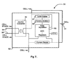
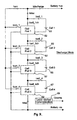
- Figure 8 shows the configuration of modules 52 described in figure 7 to implement a full active cell balancing system for a stack of four cells (61,63,65,67).
- the modular construction permits as many series connected cells as the rated isolation voltage of the DC/DC converter and communication system can tolerate.
- Figure 8 shows a battery system being supplied by a Constant Current Constant Voltage (CCCV) charger connected across Battery +ve and Battery -ve terminals.
- CCCV Constant Current Constant Voltage
- FIG. 10 shows implementation to constant voltage chargers as used with Lead Acid cell technology.
- all charge current is passed through the cell DC/DC converters.
- Each cell converter has direct control over its connected cell charge rate and so can regulate its cell voltage at an appropriate level during charge cycle.
- the DC/DC converters are all connected to the cell stack and cell balancing works in exactly the same way as above Lithium Ion implementation.
- Switch A is closed and switch B is open during charge mode.
- Switch A is open and Switch B is closed.
- the programmable logic can be programmed to operate internal heaters to warm the cells to enable additional energy release.
- the heaters deriving their power from the battery pack. This technique enables maximum energy to be released from the battery pack at low temperatures.
- the heaters may also operate in charge mode to increase charge acceptance of the battery pack thus enabling maximum energy storage.
- the programmable logic algorithms compensate for charge acceptance and charge release with cell temperature to allow accurate tracking of cell capacity.
- Protection, SoC, SoH, Active Cell Balance Control, Charger Control, Communication Bus, Microprocessor, and Memory monitoring means are integrated onto a single Application Specific Integrated Circuit using CMOS, BiCMOS or BIPOLAR semiconductor process. All electronic power circuitry would be external to the Application Specific Integrated Circuit.
- power electronic circuitry can be integrated onto the substrate as control, monitoring, acquisition, processing and communication.
- the present invention allows the integration of all the above functional blocks onto a single integrated circuit in a way that will serve a wide application base.
- This single integrated circuit can then be embedded into the battery pack to remove all battery management from the host system and in doing so reduce manufacturing cost, increase battery capacity, increase battery life, and increase system reliability.
Abstract
Description
- The present invention relates to battery management systems, to their implementation in Electronic Integrated Circuits, and more particularly to large scale integration techniques commonly known as System On Chip or System Level Integration.
- In the field of battery management, it is highly desirable to monitor and/or control a number of parameters that affect battery performance. For example, a battery management system might include some of the following functionality:
- State of Charge (SoC) measurement for determining the amount of remaining stored energy;
- State of Health (SoH) measurement for determining the battery life expectancy;
- Battery protection monitoring to ensure safe battery operation;
- Charge Control for regulation of charging current and voltage; and
- Cell Balancing to ensure maximum energy is stored and delivered without activating protection circuitry.
- Presently many different electronic circuits are employed to provide the above described functionality. Current industry implementation makes use of up to seven integrated circuits to provide a total solution with only a few devices contained within the battery pack. Cell balancing, charger, and some data processing are housed within the host system.
- Semiconductor manufacturers have developed specific electronic integrated circuits that provide one or more of these features in an attempt to reduce cost and minimise-solution size. Such examples of devices are Fuel Gauging IC's that provide SoC, Protection IC's that monitor the safe operation of the battery, Passive Cell Balancer IC's that ensure safe charging of multiple series connected battery cells, and Charger IC's that control the battery's charger unit. It therefore takes a number of integrated circuits and additional discrete circuitry to build a complete battery management system.
- Problems that are not currently addressed are:
- Accurate determination and compensation of battery self discharge current;
- Compensation of SoC for battery operational temperature; Cell balancing during discharge;
- Accurate SoH (State of Health) determination; and Application of battery management to large Cell stacks (greater than 8 series or parallel connected cells).
- A single cell Li-Ion battery provides a nominal output voltage of around 3.7V and has a narrow range of safe operation of between 3V and 4.2V. Should the cell voltage drift outwith this safe zone, through over discharge or over charging, the Li-Ion cell will be irreparably damaged and under certain circumstances there is risk of catastrophic failure resulting in fire and or explosion.
- An internal protection circuit as described earlier prevents the cell from being over charged or discharged.
- In multi-cell battery packs, cells are connected in series to provide a greater output voltage for use in applications that require a greater energy capacity such as lap top computers and electric vehicles. Each cell has slightly different electrical characteristics due to variations in assembly and chemistry. The protection circuit must act on the lowest and/or highest cell voltage in the multi-cell pack. This means that battery packs can be disabled for just a single discharged cell, thus preventing further energy being released, or a single overcharged cell preventing full charge of the battery pack. This problem significantly reduces the available charge from a multi-cell battery.
- The objective of cell balancing is to compensate for these variations in cell electrical characteristics such as impedance and capacity by ensuring that each 'series' connected cell operates with the same cell voltage and within an acceptable tolerance. Cell balancing maximises available charge in series connected multi-cell battery packs and increases life expectancy through reduction in charging cycles.
- Passive cell balancing switches a resistor across a high voltage cell to remove charge from it and pass it onto the lower cell/cells. Another possible approach would be to use a shunt regulator across each cell this would remove the need for the resistor with all cell voltage being supported by the shunt pass transistor. Both methods have two problems; firstly they both dissipate energy, secondly their only use is during the charging cycle as it would lessen battery capacity and shorten life during discharge cycle due to the additional dissipation. Current Li-Ion battery management integrated circuits that incorporate cell balancing utilise the passive approach examples being Xicor's X310 series and Texas Instruments bq29311.
- It is an object of the present invention to provide a complete battery management system. It is a further object of the invention to implement the battery management system on a single Application Specific Integrated Circuit or by using several integrated circuits with or without further discrete circuitry.
- In accordance with a first aspect of the present invention there is provided a battery pack containing: a battery; and a battery management system comprising one or more battery monitoring means and programmable logic; wherein the programmable logic is connected to the one or more battery monitoring means to modify its battery operation and report battery status; and the battery management system is embedded in the battery pack, with the battery; characterised in that the battery monitoring means comprises active cell balancing control means associated with each battery cell and operable to enable the transfer of energy from strong cells to weak cells during both the charging and discharging cycles, and wherein the active cell balancing control means is operable as an integral charger.
- Preferably, the battery monitoring means reports battery status through a communication bus to an external host.
- Implementation is applicable to all electrical energy storage systems that comprise series or parallel connected electro chemical storage elements. This includes but is not limited to Super or Ultra Capacitor's, fuel cells, NiMH, NiCd, Pb & Lithium Chemistry battery packs.
- Implementation of programmable logic enables the invention to be configured for a variety of battery chemistries.
- Preferably, the battery monitoring means is provided with data acquisition means to record battery performance parameters.
- Preferably, the programmable logic is configured to analyse data received from the one or more battery monitoring means and to modify the operation of the battery in response to said data.
- Preferably, data acquisition means is placed across each cell of the battery to collect data from said cell.
- Optionally, a data acquisition device is configured to collect data from a plurality of cells.
- Preferably, the programmable logic is configured to analyse physical data.
- Preferably, the programmable logic is configured to analyse physical data relating to the effect of temperature on battery capacity and/or the effect of temperature on battery self discharge current.
- Preferably, the programmable logic is configured to derive the actual state of charge at any operational temperature.
- Preferably, the programmable logic contains one or more look-up tables and/or algorithms.
- Preferably, the programmable logic comprises a digital microprocessor and digital memory.
- Preferably, the programmable logic comprises a digital means of communication with internal and external systems and the ability to report battery status and provide external control of a battery.
- Preferably, the programmable logic is embedded in the battery management system.
- Preferably, the battery monitoring means comprises state of charge measurement means.
- Preferably, the battery monitoring means comprises state of health measurement means.
- Preferably, the battery monitoring means comprises battery protection means.
- Preferably, the battery protection means comprises switching means to control current flow from a power source.
- Preferably, the battery monitoring means comprises charging control means.
- Preferably, the active cell balancing control comprises a switched mode converter, attachable to a primary energy source and capable of moving energy from the primary energy source to one or more cells depending upon the respective energy requirements of the cells. The primary energy source can be a battery or an external power supply.
- Preferably, the programmable logic is adapted to operate temperature control means.
- Preferably, the temperature control means comprises heating means to warm the cells.
- The primary energy source can be external to the battery pack in charge mode.
- Preferably, the primary energy source can be derived from the battery pack in active cell balancing mode
- Preferably, the active cell balancing circuitry can operate as a sulphation removal system when used in a Pb (lead acid) battery stack.
- This is a result of the ability of the active cell balancing circuitry to deliver current pulses.
- A Flyback topology can be used as a switched mode converter.
- The type of switched mode converter is not limited to flyback and can comprise other converter topologies.
- The use of a Flyback Switched Mode Converter in both discontinuous and continuous mode is an effective energy transfer device for cell balancing and cell charging as all outputs track.
- Preferably, the Flyback Switched mode converter is provided with one or more synchronous output or secondary rectifiers.
- The use of synchronous rectifiers improves energy conversion efficiency and can better steer energy to the appropriate weak cell.
- Optionally, the Flyback switched mode converter is provided with one or more output or secondary rectifier diodes.
- Preferably, a switched magnetic or capacitive converter may be configured to actively transfer energy from strong cells to weak cells within the battery pack.
- Preferably, the battery management system is provided with self discharge current measurement means.
- Preferably, the self discharge measurement means comprises a current oscillator which can be coupled to a battery when the battery is in sleep mode, the current oscillator having a temperature coefficient that corresponds to the temperature coefficient of the battery.
- Preferably the battery management system is provided with means for disabling the battery during transit, said means being provided as an instruction from the programmable logic.
- In accordance with a second aspect of the invention there is provided a battery management system of the first aspect of the invention incorporated in an application specific integrated circuit.
- In accordance with a third aspect of the invention there is provided a battery management system of the first aspect of the invention incorporated in a discrete printed circuit board.
- Preferably, application to a large cell stack can be implemented through modules that comprise individual DC/DC converters, all monitoring, communication and logic functions. Each cell in the stack is connected to its own individual cell module.
- The present invention will now be described by way of example only, with reference to the accompanying drawings in which:
-
Figure 1 is a schematic diagram of an example of the present invention; -
Figure 2 is a circuit block diagram of a first embodiment of a battery management system in accordance with the present invention; -
Figure 3 is circuit block diagram of a switched mode converter used in a second embodiment of the present invention; -
Figure 4 is a circuit block diagram of a data acquisition device suitable for use in an embodiment of the present invention; -
Figure 5 is a circuit block diagram of a data acquisition device suitable for use in an embodiment of the present invention; -
Figure 6 is a circuit block diagram of a second embodiment of the present invention; -
Figure 7 is a circuit block diagram of a digital processor and controller for use in an embodiment of the present invention with a large number of series connected cells; -
Figure 8 is a circuit block diagram showing the configuration of modules described infigure 6 where the circuit is in charge mode; -
Figure 9 is the circuit block diagram offigure 8 in discharge mode; and -
Figure 10 is the circuit block diagram offigure 8 implemented with a constant voltage charger. - As shown in
Figure 1 , the present invention incorporates battery monitoring means 20 such as active cell balancing control and status reporting, SoC measurement and reporting, SoH measurement and reporting, Protection control and status reporting, Charging control and reporting. - These battery monitoring means are programmable through the implementation of
programmable logic 30 as an embedded digital microprocessor and digital memory. The battery management system is able to communicate so with an external host through the implementation of a serial or parallel wired bus or through a wireless communication link. The programmable logic is also able to communicate with thebattery 40. - Implementation of a digital microprocessor and digital memory enables the present invention to be configured for multiple battery chemistries. In addition, the digital microprocessor and digital memory enables processing of captured data to compensate for a wide variety of physical processes not currently considered in the state of the art. In particular algorithms or look up tables can be used to compensate for the effect of temperature on battery capacity and for the effect of temperature on battery self discharge current. Algorithms are also used to establish cell aging from variation in complex cell impedance coupled with depth of discharge history. The complex and static impedance being derived from the measurements made by the data acquisition modules.
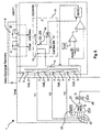
- An example of the present invention is shown in
Figure 2 . - The implementation.of a Flyback Switched mode power supply either operating in the discontinuous or continuous mode offers a source of charge current for each series connected cell within the battery. Multiple secondary windings on a single coupled
inductor 5 enable the sharing of energy that is delivered to the coupled inductor through the primary inductor winding 5. The primary energy source can be from an external charge source or if connected to the battery output from the battery itself. - Implementation can also comprise individual switch mode power supply converters without coupled secondary windings.
- When connected to the battery output the circuit is configured for Active Cell Balancing. In this mode energy is taken from the battery pack and delivered to the weakest (lowest charge state) cell effectively transferring energy from higher capacity cells into lower capacity cells to enable the maximum energy to be withdrawn from the battery pack. Without Active Cell Balancing the battery's protection circuit would turn off the battery output when the lowest charged cell was depleted even though energy remained in higher capacity cells.
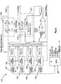
- An enhancement of the Active Cell Balancer circuit shown as a Flyback switched mode power supply in
figure 1 is to place individual data acquisition devices across each cell as shown infigure 3 . This enables greater accuracy of capacity determination in accommodating energy lost through cell balancing. It is to be noted that Active Cell balancing provides greater accuracy due to its significantly higher efficiency than Passive Cell balancing. This configuration can also report individual cell absolute and relative capacities as they age so providing useful service information. Typical data acquisition devices are shown infigures 4 and 5 . - The
data acquisition device 83 offigure 4 comprises inputs from acell 84, 85 a low offset compensatingdifferential amplifier 86 connected to ananalogue multiplexer 87 which also has atemperature sensor 88 connected to its input. The analogue todigital converter 89 provides the input to register 90 and communications means 91. A synchronisingclock input 92 is also provided. - An additional enhancement to the Active Cell Balancer shown as a Flyback converter in
figures 2 and3 is to replace all output diodes with synchronous rectifiers (figure 6 ). In this embodiment the microprocessor can select which synchronous rectifier to activate in order to better steer energy into the weakest cell without energy escaping into higher charged cells which reduces overall efficiency. In this embodiment thedata acquisition device 93 has, in addition to those features shown infigure 4 , acontrol port 94 that activates the synchronous rectifier (figure 5 ). - A four cell battery management system incorporating active cell balancing is described in
figure 2 ,3 and6 . - The system contains six functional blocks
- The battery protection block that protects the battery from excessive charge and discharge.
- The charger block that replenishes charge once the battery is discharged.
- The data acquisition block that acquires state of battery (voltage, current, temperature, capacity) information.
- The coulomb counter block that accurately determining the available capacity of the battery (fuel gauge).
- The digital processor and digital bus communication block that processes data and hosts communications.
- The Cell Balancing used to maximise the available charge in series connected multi-cells.
- The Active Cell Balancing unit can be configured to act as the charger thereby eliminating the need for an additional charger circuit.
- Referring to
figure 2 battery protection 9 is afforded through two power switches referenced A and B. These two switches are controlled by logic that operate each switch depending on the operating condition sensed by the data acquisition circuitry. The two switches enable either full charge/discharge (two way current flow), charge only (one way current flow into battery), discharge only (one way current flow out of the battery) and finally in a fault condition both switches are off enabling no current to flow into or out of the battery. - It is to be noted that Li-Ion batteries have a very narrow window of safe operation and if subject to operating conditions outwith this window extensive damage can result to the Li-Ion cell/battery and in extreme situations there is risk of excessive heat/explosion. Battery protection is therefore for Li-Ion cells/batteries.
- The conditional state of protection circuitry and operating mode can be relayed to the host system by the digital bus communication link between battery pack and host system.
- Referring to
figure 2 thebattery charger 11 is represented by the block identified as reference C. The purpose of the charger block is to replenish the battery charge from a variety of power sources such as a mains outlet block, or vehicle 12V/24V socket. The charger block is under control of the internal data processor and the host system controller via the digital bus communication link between battery pack and host system. - The Charger block is function performed by the Active Cell Balancer block. Two switches controlled by
CH_EN 19 andCellBalEN 17 select which mode is appropriate. The two switches are never on at the same time. - The charger can operate in a number of modes accommodating a variety of different battery cell chemistries. These modes include constant current followed by constant voltage and float charging. A detailed description of operation now follows:-
- The purpose of the data acquisition circuitry is to provide measurements of all the batteries vital performance parameters such as cell voltage, current flow and temperature. These parameters are analogue so they need to be sensed (21, 22) and then converted into
digital signals 25 before being handed over to the digital processor. Two 12 bit Analogue toDigital Converters 25, ADC's, are used. Theinputs 22 to the ADC's are multiplexed 21 to save on operating current and circuit area. Oneanalogue multiplexer 21 and onedigital multiplexer 27 are used. An acquisition register 29 is provided to hold the acquired data for further processing. All this circuitry is represented by the reference D infigure 2 . - The analogue and digital multiplexers are programmable to accommodate different numbers of series connected cells.
- The embodiment described in
figure 3 and6 show each cell having its own data acquisition device (133,233,135,235) each reporting to the main micro controller through a common serial communication bus. This improves the accuracy of data collected specific to each individual cell. - To accurately determine available capacity of battery (fuel gauge) the current into and out of the battery is sensed and integrated (accumulated). The charge is counted going into the battery and the charge is counted leaving the battery the difference between the two counts is the estimated remaining battery capacity. An ultra low offset self compensating
differential amplifier 34,figure 2 reference F, senses the voltage across thecurrent sense resistor 41. The maximum voltage corresponding to maximum current will be around +/-100mV. The output of the differential amplifier is then converted to a digital value by an ADC and placed in the acquisition register for later processing by the arithmetic unit and accumulated current register. Current is integrated by the cumulative addition of sampled current in the ACC.CURRENT register 45. The output of the current ADC is signed in 2's complement to enable subtraction for discharge. - In the embodiment described by
figures 3 and6 each cell has its own Coulomb Counter to improve accuracy of measurement and provide additional state of health information. - A digital signal processor is required to control system operation, collate acquired data, process data, communicate data with host system, and accept system control commands from host system via the communication digital bus.
- The digital processor and digital bus communication functionality of
figure 2 provide the programmable logic functions which operate upon the data acquired relating to cell performance. Aclock 71 and clock enable 72 are provided along with a threshold register which contains threshold valves of many of the measurable physical parameters of a cell such as Ch_Imax (Charge Current Maximum). The arithmetic unit and controllogic 75 is programmable in a manner selected by the user depending upon for instance the physicial properties of the cells in the battery. -
System register 77 which controls status and mode of the system as well as anextraction register 79 and communications (bus 81) are also shown. - The programmable logic is programmed to optimise battery performance in response to changes in battery performance identified through acquired data.
- The present invention uses active cell balancing. Active cell balancing makes use of switching capacitors or magnetic circuits to balance each cell voltage. The active approach can be applied in both the charge and discharge cycle furthermore the efficiency of conversion is greatly increased. There are potentially many different types of active cell balancing circuits, some of the simplest make use of capacitors that are switched across each cell in rotation. The capacitors transfer charge to and from each cell to balance their respective voltages. As a consequence of the size of capacitors and switching frequency required this configuration works best for low capacity batteries.
- Other possible active cell balancing schemes can make use of magnetic switching circuits such as the Buck and Flyback topologies. The Flyback approach is simple to implement and has the inherent ability to distribute energy without the need for any complex control circuitry. However, the design of the Coupled Inductor is important because all leakage inductances must balance within limits to enable accurate charge distribution.
- Given the application tolerances for Li-Ion the Flyback approach has been adopted in the embodiment of the invention shown in
figures 2 and3 and6 . -
Figure 2 shows a four cell system. However, the digital processor and controller can be made flexible to accommodate a defined maximum number of cells. The cell number register can be written to via the serial bus to define the number of cells for any given application. This data register is then used by the controller to configure all Analogue and Digital multiplexers and data registers to control a specific number of cells for that programmed application. Though the maximum number of series connected cells is envisaged to be no more than eight in this embodiment. For application to a greater number of series connected cells the embodiment described byfigures 7 and8 and10 would enable systems to be built that would support application to heavy industrial devices such as electric vehicles and standby battery banks that generally require terminal voltages exceeding 300V. - The cell balancing circuit activation can be enabled outside of two programmable thresholds VHbal and VLbal. This will prevent the cell balancing circuitry being active during most operating conditions and hence save on battery life. Only when any cell voltage is higher than the VHbal or lower than the VLbal thresholds will the cell balancing circuitry be active.
- Accurate self discharge estimate: When the battery is lying idle with no current being drawn from it there exists a low internal self discharge current that changes with cell temperature and cell voltage. If the appliance is switched off for an extended period of time the indicated remaining capacity will be in error due to the extended period of self discharge. The present invention provides a means of estimating the self discharge current during power down and thus provides a far more accurate indication of remaining capacity when the appliance is turned on after an extended power off period.
- The present invention uses an ultra low current oscillator (reference G), that operates when the battery is in sleep mode. The oscillator has a strong temperature coefficient that corresponds with that of the battery self discharge temperature profile. The count obtained from the sleep counter is processed with the capacity register on recovery from sleep mode to provide an accurate estimate of remaining capacity.
- The ultra low current oscillator prevents further drain on battery during sleep mode and to match the temperature coefficient to that of the battery cell discharge profile.
- Safe Transportation and Storage: Use of internal protection circuit to disable battery pack when in transportation, storage or host demand. The digital serial bus enables commands to be sent to the battery management system controller to disable the battery on demand.
- Temperature variation of State of Charge: This effect is particularly acute for Lithium based cell chemistries. The available capacity from a cell can significantly reduce as temperature falls. The full capacity is restored upon temperature recovery. The implementation of an embedded digital microprocessor and digital memory enables acquired capacity data to be processed using look up tables or algorithms to compensate for this temperature affect.
-
Figure 8 shows the configuration ofmodules 52 described infigure 7 to implement a full active cell balancing system for a stack of four cells (61,63,65,67). The modular construction permits as many series connected cells as the rated isolation voltage of the DC/DC converter and communication system can tolerate.Figure 8 shows a battery system being supplied by a Constant Current Constant Voltage (CCCV) charger connected across Battery +ve and Battery -ve terminals. At the start of the charge cycle a constant current, Ich, is supplied to the cell stack. Current is diverted away from the cell stack, Istac, by CELL Pod DC/DC converters, Icon, to support cells that have lower voltages. This reduces the rate at which higher voltage cells charge and increases the rate at which lower voltage cells charge. It is through this mechanism that each cell voltage may be balanced during the charge cycle. This implementation relies on their being a constant current charge source which is valid for Lithium Ion and many other cell chemistries. - In the discharge cycle as shown in
figure 9 current is taken from the cell stack by DC/DC converter/converters to boost the cell voltage/voltages of cells that have a lower voltage. In this embodiment Istac>=Idischarge (Istack=Icon+Idischarge) though individual cells of low voltage will have significantly lower current than Istack with the DC/DC converter supporting Istack though bypassing each low voltage cell. For low voltage cells Icell_x<Istack with Icell_xch+Icell=Istack. -
Figure 10 shows implementation to constant voltage chargers as used with Lead Acid cell technology. In this embodiment all charge current is passed through the cell DC/DC converters. Each cell converter has direct control over its connected cell charge rate and so can regulate its cell voltage at an appropriate level during charge cycle. When in discharge mode the DC/DC converters are all connected to the cell stack and cell balancing works in exactly the same way as above Lithium Ion implementation. Switch A is closed and switch B is open during charge mode. In discharge mode Switch A is open and Switch B is closed. - In an alternative embodiment the programmable logic can be programmed to operate internal heaters to warm the cells to enable additional energy release. The heaters deriving their power from the battery pack. This technique enables maximum energy to be released from the battery pack at low temperatures. The heaters may also operate in charge mode to increase charge acceptance of the battery pack thus enabling maximum energy storage. The programmable logic algorithms compensate for charge acceptance and charge release with cell temperature to allow accurate tracking of cell capacity.
- In one preferred embodiment of the invention, Protection, SoC, SoH, Active Cell Balance Control, Charger Control, Communication Bus, Microprocessor, and Memory monitoring means are integrated onto a single Application Specific Integrated Circuit using CMOS, BiCMOS or BIPOLAR semiconductor process. All electronic power circuitry would be external to the Application Specific Integrated Circuit.
- In addition all power electronic circuitry can be integrated onto the substrate as control, monitoring, acquisition, processing and communication.
- Other embodiments make use of several integrated circuits and additional electronic circuitry.
- The present invention allows the integration of all the above functional blocks onto a single integrated circuit in a way that will serve a wide application base. This single integrated circuit can then be embedded into the battery pack to remove all battery management from the host system and in doing so reduce manufacturing cost, increase battery capacity, increase battery life, and increase system reliability.
- Improvements and modifications may be incorporated herein without deviating from the scope of the invention.
Claims (31)
- A battery pack containing:a battery; anda battery management system comprising one or more battery monitoring means andprogrammable logic;wherein the programmable logic is connected to the one or more battery monitoring means to modify its battery operation and report battery status; and the battery management system is embedded in the battery pack, with the battery;characterised in that the battery monitoring means comprises active cell balancing control means associated with each battery cell and operable to enable the transfer of energy from strong cells to weak cells during both the charging and discharging cycles, and wherein the active cell balancing control means is operable as an integral charger.
- A battery pack as claimed in claim 1, wherein the battery monitoring means reports battery status through a communication bus to an external host.
- A battery pack as claimed in claim 1 or 2, wherein the battery monitoring means is provided with data acquisition means to record battery performance.
- A battery pack as claimed in any preceding claim, wherein the programmable logic is configured to analyse data received from the one or more battery monitoring means and to modify the operation of the battery in response to said data.
- A battery pack as claimed in claim 3, wherein the data acquisition means is placed across each cell of the battery to collect data from said cell.
- A battery pack as claimed in claim 3 or claim 5, wherein the data acquisition means is configured to collect data from a plurality of cells.
- A battery pack as claimed in any preceding claim, wherein the programmable logic is configured to analyse physical data.
- A battery pack as claimed in any preceding claim wherein, the programmable logic is configured to analyse physical data relating to the effect of temperature on battery capacity and/or the effect of temperature on battery self discharge current.
- A battery pack as claimed in any preceding claim wherein, the programmable logic is conjured to derive the actual state of charge at any operational temperature.
- A battery pack as claimed in any preceding claim wherein, the programmable logic contains one or more look-up tables and/or algorithms.
- A battery pack as claimed in any preceding claim wherein, the programmable logic comprises a digital microprocessor and digital memory.
- A battery pack as claimed in any preceding claim wherein, the programmable logic comprises a digital means of communication with internal and external systems and the ability to report battery status and provide external control of a battery,
- A battery pack as claimed in any preceding claim wherein, the programmable logic is embedded in the battery management system.
- A battery pack as claimed in any preceding claim wherein, the battery monitoring means comprises state of charge measurement means.
- A battery pack as claimed in any preceding claim wherein, the battery monitoring means comprises state of health measurement means.
- A battery pack as claimed in any preceding claim wherein, the battery monitoring means comprises battery protection means.
- A battery pack as claimed in any preceding claim wherein, the battery protection means comprises switching means to control current flow from a power source.
- A battery pack as claimed in any preceding claim wherein, the battery monitoring means comprises charging control means.
- A battery pack as claimed in claim 1 wherein, the active cell balancing control comprises a switched mode converter, attachable to a primary energy source and capable of moving energy from the primary energy source to one or more cells depending upon the respective energy requirements of the cells.
- A battery pack as claimed in any preceding claim, wherein the programmable logic is adapted to operate temperature control means.
- A battery pack as claimed in claim 20, wherein the temperature control means comprises heating means to warm the cells.
- A battery pack as claimed in claim 19, wherein the active cell balancing means operates as a sulphation removal system when used in a Pb (lead acid) battery stack.
- A battery pack as claimed in claim 19, wherein a Flyback topology can be used as a switched mode converter.
- A battery pack as claimed in claim 23, wherein the Flyback switched mode converter is provided with one or more synchronous output or secondary rectifiers.
- A battery pack as claimed in claim 23 or claim 24, wherein the Flyback switched mode converter is provided with one or more output, or secondary rectifier diodes.
- A battery pack as claimed in any preceding claim, wherein a switched magnetic or capacitive converter may be configured to actively transfer energy from strong cells to weak cells within the battery pack.
- A battery pack as claimed in any preceding claim, wherein the battery management system is provided with self discharge current measurement means.
- A battery pack as claimed in claim 27, wherein the self discharge measurement means comprises a current oscillator which can be coupled to a battery when the battery is in sleep mode, the current oscillator having a temperature coefficient that corresponds to the temperature coefficient of the battery.
- A battery pack as claimed in any preceding clam wherein the battery management system is provided with means for disabling the battery during transit, said means being provided as an instruction from the programmable logic.
- A battery pack as claimed in any preceding claim, wherein the battery management system is incorporated in an application specific integrated circuit.
- A battery pack as claimed in any of the preceding claims, wherein the battery management system is incorporated in a discrete printed circuit board.
Applications Claiming Priority (2)
| Application Number | Priority Date | Filing Date | Title |
|---|---|---|---|
| GB0502274A GB0502274D0 (en) | 2005-02-04 | 2005-02-04 | Battery management system |
| PCT/GB2006/000385 WO2006082425A1 (en) | 2005-02-04 | 2006-02-06 | Battery management system |
Publications (2)
| Publication Number | Publication Date |
|---|---|
| EP1846776A1 EP1846776A1 (en) | 2007-10-24 |
| EP1846776B1 true EP1846776B1 (en) | 2011-08-03 |
Family
ID=34307942
Family Applications (1)
| Application Number | Title | Priority Date | Filing Date |
|---|---|---|---|
| EP06709632A Active EP1846776B1 (en) | 2005-02-04 | 2006-02-06 | Battery management system |
Country Status (8)
| Country | Link |
|---|---|
| US (1) | US20080278115A1 (en) |
| EP (1) | EP1846776B1 (en) |
| AT (1) | ATE519124T1 (en) |
| AU (1) | AU2006210743B2 (en) |
| DK (1) | DK1846776T3 (en) |
| ES (1) | ES2371059T3 (en) |
| GB (1) | GB0502274D0 (en) |
| WO (1) | WO2006082425A1 (en) |
Cited By (1)
| Publication number | Priority date | Publication date | Assignee | Title |
|---|---|---|---|---|
| DE102014201054A1 (en) * | 2014-01-22 | 2015-07-23 | Robert Bosch Gmbh | Method and device for operating a battery, in particular a lithium ion battery, in a consumer |
Families Citing this family (83)
| Publication number | Priority date | Publication date | Assignee | Title |
|---|---|---|---|---|
| TWI340515B (en) | 2006-12-01 | 2011-04-11 | O2Micro Int Ltd | Battery pack, electronic system with cell monitoring and the method for battery pack monitoring thereof |
| US20090099697A1 (en) * | 2007-06-11 | 2009-04-16 | Eair, Llc | Power Supply Switch for Dual Powered Thermostat, Power Supply for Dual Powered Thermostat, and Dual Powered Thermostat |
| US8098048B2 (en) * | 2007-06-15 | 2012-01-17 | The Gillette Company | Battery charger with integrated cell balancing |
| US7433794B1 (en) | 2007-07-18 | 2008-10-07 | Tesla Motors, Inc. | Mitigation of propagation of thermal runaway in a multi-cell battery pack |
| US7720576B2 (en) * | 2007-11-21 | 2010-05-18 | Lennox Industries Inc. | Intelligent auxiliary power supply system with current and temperature monitoring capabilities |
| JP5179851B2 (en) * | 2007-11-30 | 2013-04-10 | オーツー マイクロ, インコーポレーテッド | Battery pack with embedded cell monitor, electronic system, and method for monitoring a battery pack |
| US7960945B1 (en) * | 2008-01-30 | 2011-06-14 | Google Inc. | Estimating remaining use time of a mobile device |
| US20130033102A1 (en) * | 2008-02-20 | 2013-02-07 | Lonnie Calvin Goff | Embedded battery management system and methods |
| DE102008023292A1 (en) * | 2008-05-13 | 2009-12-03 | Clean Mobile Ag | Electrical drive system for bicycle, has secondary switches provided for parallel connection of secondary coils with respective batteries, where secondary switches are switched independent of each other |
| DE102008023291A1 (en) * | 2008-05-13 | 2009-11-19 | Clean Mobile Ag | Electrical light vehicle i.e. bicycle, has secondary switches for parallel switching of secondary coils with accumulators, respectively where secondary switches are switchable independent of each other |
| US8847551B2 (en) * | 2009-02-09 | 2014-09-30 | Younicos, Inc. | Discharging batteries |
| US9030169B2 (en) * | 2009-03-03 | 2015-05-12 | Robert Bosch Gmbh | Battery system and method for system state of charge determination |
| CN102449495B (en) * | 2009-06-03 | 2014-12-31 | 三菱重工业株式会社 | Battery state of charge calculation device |
| DE102009024657A1 (en) * | 2009-06-12 | 2010-12-16 | Siemens Aktiengesellschaft | Method for operating a high-conduction battery and apparatus suitable for carrying out the method |
| TWI413788B (en) * | 2009-06-22 | 2013-11-01 | Quanta Comp Inc | A battery gas-gauge circuit and method thereof |
| US20110057626A1 (en) * | 2009-07-16 | 2011-03-10 | Demain International Pty Ltd. | Power supply and charging circuit for high energy capacitors |
| DE102009046501A1 (en) * | 2009-11-06 | 2011-05-12 | SB LiMotive Company Ltd., Suwon | Battery system with DC / DC converters |
| US20110144840A1 (en) * | 2009-12-15 | 2011-06-16 | Ise Corporation | Expandable Energy Storage Control System and Method |
| TWI405996B (en) * | 2009-12-29 | 2013-08-21 | Lite On Electronics Guangzhou | Cell pack balancing method |
| KR101057542B1 (en) * | 2010-01-26 | 2011-08-17 | 에스비리모티브 주식회사 | Battery Management System and Its Driving Method |
| US20110187377A1 (en) * | 2010-02-03 | 2011-08-04 | Dale Boysen | Battery Charger Tester With Individual Cell Temperature Measurement |
| US8729904B2 (en) | 2010-03-15 | 2014-05-20 | Launchpoint Energy And Power Llc | Method and system for safe operation of large lithium-ion batteries |
| WO2011117089A1 (en) * | 2010-03-24 | 2011-09-29 | Magna E-Car Systems Gmbh & Co Og | Monitoring system for an energy storage cell |
| CN101834457B (en) * | 2010-04-30 | 2012-11-07 | 重庆长安汽车股份有限公司 | Lithium battery management system |
| CN101902060B (en) * | 2010-07-23 | 2012-07-04 | 重庆大学 | Charge-discharge battery pack equilibrium management system |
| KR101193168B1 (en) * | 2010-08-20 | 2012-10-19 | 삼성에스디아이 주식회사 | Power storage system, controlling method of the same, and recording medium storing program to execute the method |
| DE102010039913A1 (en) * | 2010-08-30 | 2012-03-01 | Sb Limotive Company Ltd. | A method for balancing states of charge of a battery with a plurality of battery cells and a corresponding battery management system and a battery |
| CA2810369A1 (en) * | 2010-09-02 | 2012-03-08 | Proterra Inc. | Systems and methods for battery management |
| CN101976747A (en) * | 2010-09-16 | 2011-02-16 | 南京双登科技发展研究院有限公司 | Composite power supply for light electric vehicle |
| US9851412B2 (en) | 2010-11-09 | 2017-12-26 | International Business Machines Corporation | Analyzing and controlling performance in a composite battery module |
| WO2012068732A1 (en) | 2010-11-25 | 2012-05-31 | Kenneth Hamilton Norton | A battery pack assembly |
| KR20140008404A (en) * | 2011-02-21 | 2014-01-21 | 에스톨, 인코포레이티드 | Power supply and power control circuitry |
| US10862323B2 (en) | 2011-04-28 | 2020-12-08 | Zoll Circulation, Inc. | Battery management system for control of lithium power cells |
| CN108649655B (en) | 2011-04-28 | 2022-06-24 | 佐尔循环公司 | System for supplying power to equipment and intelligent battery pack system |
| US9825475B2 (en) | 2011-04-28 | 2017-11-21 | Zoll Circulation, Inc. | System and method for automated detection of battery insert |
| US9437848B2 (en) | 2011-04-28 | 2016-09-06 | Zoll Circulation, Inc. | Latch mechanism for battery retention |
| US8729957B2 (en) | 2011-04-28 | 2014-05-20 | Zoll Circulation, Inc. | Battery management system with MOSFET boost system |
| JP2014519796A (en) | 2011-04-28 | 2014-08-14 | ゾール サーキュレイション インコーポレイテッド | Distributed distribution of battery management parameters |
| EP3561995A1 (en) | 2011-04-28 | 2019-10-30 | ZOLL Circulation, Inc. | System and method for tracking and archiving battery performance data |
| KR20120134415A (en) * | 2011-06-02 | 2012-12-12 | 에스케이이노베이션 주식회사 | Method for estimating state of health |
| JP5659967B2 (en) | 2011-06-24 | 2015-01-28 | ソニー株式会社 | Monitoring device |
| US9097774B2 (en) | 2011-07-14 | 2015-08-04 | Southwest Electronic Energy Corporation | Short detection in battery cells |
| US8796993B2 (en) * | 2011-09-12 | 2014-08-05 | Southwest Electronic Energy Corporation | Historical analysis of battery cells for determining state of health |
| US9746527B2 (en) * | 2011-11-21 | 2017-08-29 | Blackberry Limited | Method and apparatus for battery charge level estimation |
| WO2013104047A1 (en) * | 2012-01-09 | 2013-07-18 | Panacis, Inc. | A system for power balance monitoring in batteries |
| CN103248072A (en) * | 2012-02-02 | 2013-08-14 | 李佳原 | Discharge type battery management system and method thereof |
| US20130214739A1 (en) * | 2012-02-20 | 2013-08-22 | Jia-Yuan Lee | Charge type battery management system and method thereof |
| US20130214741A1 (en) * | 2012-02-20 | 2013-08-22 | Jia-Yuan Lee | Discharge type battery management system and method thereof |
| US9037424B2 (en) | 2012-05-01 | 2015-05-19 | Caterpillar Inc. | Systems and methods for detecting ultracapacitor cell short circuits |
| US9190862B2 (en) * | 2012-08-23 | 2015-11-17 | Qualcomm Incorporated | Charging current calibration |
| WO2014045745A1 (en) * | 2012-09-18 | 2014-03-27 | Necエナジーデバイス株式会社 | Power storage system and battery protection method |
| WO2014070831A1 (en) * | 2012-10-30 | 2014-05-08 | Board Of Trustees Of The University Of Alabama | Distributed battery power electronics architecture and control |
| US9787108B2 (en) * | 2012-11-05 | 2017-10-10 | Tws (Macau Commercial Offshore) Limited | Enhanced battery management system |
| GB201219863D0 (en) * | 2012-11-05 | 2012-12-19 | Tws Total Produtos Com Offshore De Macau Limitada | Enhanced battery management system |
| KR101428293B1 (en) * | 2012-12-18 | 2014-08-07 | 현대자동차주식회사 | Sub battery charge method of electric vehicle |
| CN103117576B (en) * | 2013-02-01 | 2015-01-21 | 四川电力科学研究院 | Storage battery voltage balancing device |
| US20150180260A1 (en) * | 2013-12-20 | 2015-06-25 | Metal Industries Research & Development Centre | Power supply with current sharing control and the battery module |
| US9431837B2 (en) | 2014-04-30 | 2016-08-30 | Johnson Controls Technology Company | Integrated battery management system and method |
| US9559536B2 (en) | 2014-04-30 | 2017-01-31 | Johnson Controls Technology Company | State of charge indicator method and system |
| US9437850B2 (en) | 2014-04-30 | 2016-09-06 | Johnson Controls Technology Company | Battery construction for integration of battery management system and method |
| US9692240B2 (en) | 2014-04-30 | 2017-06-27 | Johnson Controls Technology Company | Battery sleep mode management method and system |
| DE102014212933B3 (en) * | 2014-07-03 | 2015-06-25 | Siemens Aktiengesellschaft | Apparatus and method for state of charge compensation for a battery system |
| JP6264396B2 (en) * | 2014-09-19 | 2018-01-24 | 株式会社村田製作所 | Monitoring device, power supply device, monitoring method, power storage system, electronic device, electric vehicle, and power system |
| CN104868514A (en) * | 2014-10-22 | 2015-08-26 | 北汽福田汽车股份有限公司 | Balanced current acquisition device, active balance efficiency calculation method, and system |
| US11660980B2 (en) * | 2014-12-04 | 2023-05-30 | The Regents Of The University Of Michigan | Energy conscious warm-up of lithium-ion cells from sub-zero temperatures |
| CN108141034B (en) * | 2015-04-03 | 2020-01-24 | 上海新进半导体制造有限公司 | Embedded battery protection circuit, control circuit and signal processing circuit |
| US10031567B2 (en) | 2015-06-09 | 2018-07-24 | Microsoft Technology Licensing, Llc | Offline battery management in a device |
| US10243192B2 (en) * | 2015-09-09 | 2019-03-26 | Bren-Tronics, Inc. | Modular battery case for prismatic cells and portable off-grid power storage and delivery system |
| CN105262159B (en) * | 2015-09-28 | 2018-09-07 | 香港城市大学深圳研究院 | Charge and discharge control super capacitance management device and its system with mouth |
| US11201378B2 (en) * | 2016-05-17 | 2021-12-14 | Faraday & Future Inc. | Battery monitor protection |
| EP3299966A3 (en) * | 2016-08-29 | 2018-05-30 | Rohm Co., Ltd. | Semiconductor package |
| US20180097376A1 (en) * | 2016-10-03 | 2018-04-05 | Hybrid Power Solutions Inc. | Battery pack and method of operation therefor |
| TWI627813B (en) | 2016-12-20 | 2018-06-21 | 財團法人工業技術研究院 | Battery management system and method thereof |
| KR102376469B1 (en) * | 2017-03-24 | 2022-03-22 | 한국전자통신연구원 | Battery charging system including battery gauge |
| CN112313521B (en) * | 2018-06-27 | 2023-06-13 | 新唐科技日本株式会社 | Battery monitoring device, integrated circuit, and battery monitoring system |
| KR102321508B1 (en) * | 2018-06-29 | 2021-11-04 | 엘에스엠트론 주식회사 | Ultra-Capacitor Module |
| CN111976537B (en) * | 2019-05-24 | 2022-06-24 | 北京车和家信息技术有限公司 | Battery management circuit, battery management system, control method of battery management system and electric vehicle |
| IT201900024883A1 (en) * | 2019-12-19 | 2021-06-19 | Flash Battery S R L | ARCHITECTURE OF A HIGH CURRENT BALANCING SYSTEM FOR BATTERIES |
| CN111864136B (en) * | 2020-07-08 | 2022-06-17 | 中北大学 | Composite storage battery pack device with low-temperature starting and temperature adjusting functions and using method |
| JPWO2022186375A1 (en) * | 2021-03-05 | 2022-09-09 | ||
| CN113212247A (en) * | 2021-06-18 | 2021-08-06 | 中国第一汽车股份有限公司 | Management system and new energy automobile of power battery package |
| CN113552487B (en) * | 2021-06-24 | 2023-04-07 | 武汉昊诚锂电科技股份有限公司 | Self-discharge measurement and service life evaluation method of lithium secondary battery |
| CN115149131B (en) * | 2022-06-29 | 2023-04-07 | 东莞光亚智能科技有限公司 | Monitoring system and monitoring method for lithium battery formation and capacity-grading power supply |
Family Cites Families (9)
| Publication number | Priority date | Publication date | Assignee | Title |
|---|---|---|---|---|
| TW269727B (en) * | 1995-04-03 | 1996-02-01 | Electrosource Inc | Battery management system |
| US6184656B1 (en) * | 1995-06-28 | 2001-02-06 | Aevt, Inc. | Radio frequency energy management system |
| US5982143A (en) * | 1996-08-27 | 1999-11-09 | The University Of Toledo | Battery equalization circuit with ramp converter and selective outputs |
| DE69730413T2 (en) * | 1996-11-21 | 2005-09-08 | Koninklijke Philips Electronics N.V. | BATTERY CONTROL SYSTEM AND BATTERY SIMULATOR |
| US6504344B1 (en) * | 1997-07-03 | 2003-01-07 | William Adams | Monitoring battery packs |
| US6002240A (en) * | 1997-12-12 | 1999-12-14 | Dell Usa, L.P. | Self heating of batteries at low temperatures |
| DE19756744A1 (en) * | 1997-12-19 | 1999-07-01 | Elektron Bremen | Operating battery management system e.g. for forklift trucks |
| EA200100787A1 (en) * | 1999-01-18 | 2001-12-24 | ФАРНОУ ТЕКНОЛОДЖИЗ ПиТиВай. ЛТД. | ENERGY METER |
| AU2003295715A1 (en) * | 2002-11-25 | 2004-06-18 | Tiax Llc | Cell balancing system for equalizing state of charge among series-connected electrical energy storage units |
-
2005
- 2005-02-04 GB GB0502274A patent/GB0502274D0/en not_active Ceased
-
2006
- 2006-02-06 EP EP06709632A patent/EP1846776B1/en active Active
- 2006-02-06 AU AU2006210743A patent/AU2006210743B2/en not_active Ceased
- 2006-02-06 AT AT06709632T patent/ATE519124T1/en active
- 2006-02-06 WO PCT/GB2006/000385 patent/WO2006082425A1/en active Application Filing
- 2006-02-06 US US11/815,430 patent/US20080278115A1/en not_active Abandoned
- 2006-02-06 DK DK06709632.1T patent/DK1846776T3/en active
- 2006-02-06 ES ES06709632T patent/ES2371059T3/en active Active
Cited By (1)
| Publication number | Priority date | Publication date | Assignee | Title |
|---|---|---|---|---|
| DE102014201054A1 (en) * | 2014-01-22 | 2015-07-23 | Robert Bosch Gmbh | Method and device for operating a battery, in particular a lithium ion battery, in a consumer |
Also Published As
| Publication number | Publication date |
|---|---|
| WO2006082425A1 (en) | 2006-08-10 |
| US20080278115A1 (en) | 2008-11-13 |
| AU2006210743B2 (en) | 2010-12-09 |
| EP1846776A1 (en) | 2007-10-24 |
| ATE519124T1 (en) | 2011-08-15 |
| GB0502274D0 (en) | 2005-03-09 |
| DK1846776T3 (en) | 2011-11-21 |
| ES2371059T3 (en) | 2011-12-27 |
| AU2006210743A1 (en) | 2006-08-10 |
Similar Documents
| Publication | Publication Date | Title |
|---|---|---|
| EP1846776B1 (en) | Battery management system | |
| EP2706646B1 (en) | Cell balancing system | |
| US9231440B2 (en) | Power supply apparatus and controlling method of the same | |
| US10347952B2 (en) | Battery system | |
| US10074997B2 (en) | Method and apparatus for creating a dynamically reconfigurable energy storage device | |
| US9231407B2 (en) | Battery system, method of controlling the same, and energy storage system including the battery system | |
| ES2910011T3 (en) | electrical energy storage device | |
| US7282814B2 (en) | Battery controller and method for controlling a battery | |
| RU2546978C2 (en) | Battery and battery control system | |
| US20130134943A1 (en) | Method for balancing the voltages of electrochemical cells connected in several parallel branches | |
| US20060091854A1 (en) | Power monitoring and balancing device | |
| WO2018231573A1 (en) | System and method for operating a dual battery system | |
| US20170141598A1 (en) | Electric battery comprising an electronic management system | |
| EP2926434B1 (en) | Thin film microbattery charge and output control | |
| JP7276893B2 (en) | Power supply system and management device | |
| KR101923515B1 (en) | Efficient energy storage system for monitoring and controlling battery periodically | |
| JP2003272713A (en) | Power source device | |
| KR102151652B1 (en) | Using Cuk Converter topology Li-ion battery cell balancing strategy | |
| Bhardwaj | Implementing a DC UPS with Battery’s State of Charge Estimation Based on Coulomb-Counting Method | |
| RU222970U1 (en) | Uninterruptible DC power supply | |
| Niyama et al. | Design process of a battery management system | |
| KR20220129735A (en) | Modular battery management system | |
| JP2020018085A (en) | Electrical power system and management device |
Legal Events
| Date | Code | Title | Description |
|---|---|---|---|
| PUAI | Public reference made under article 153(3) epc to a published international application that has entered the european phase |
Free format text: ORIGINAL CODE: 0009012 |
|
| 17P | Request for examination filed |
Effective date: 20070904 |
|
| AK | Designated contracting states |
Kind code of ref document: A1 Designated state(s): AT BE BG CH CY CZ DE DK EE ES FI FR GB GR HU IE IS IT LI LT LU LV MC NL PL PT RO SE SI SK TR |
|
| DAX | Request for extension of the european patent (deleted) | ||
| 17Q | First examination report despatched |
Effective date: 20090325 |
|
| GRAP | Despatch of communication of intention to grant a patent |
Free format text: ORIGINAL CODE: EPIDOSNIGR1 |
|
| GRAC | Information related to communication of intention to grant a patent modified |
Free format text: ORIGINAL CODE: EPIDOSCIGR1 |
|
| GRAC | Information related to communication of intention to grant a patent modified |
Free format text: ORIGINAL CODE: EPIDOSCIGR1 |
|
| GRAS | Grant fee paid |
Free format text: ORIGINAL CODE: EPIDOSNIGR3 |
|
| GRAA | (expected) grant |
Free format text: ORIGINAL CODE: 0009210 |
|
| AK | Designated contracting states |
Kind code of ref document: B1 Designated state(s): AT BE BG CH CY CZ DE DK EE ES FI FR GB GR HU IE IS IT LI LT LU LV MC NL PL PT RO SE SI SK TR |
|
| REG | Reference to a national code |
Ref country code: GB Ref legal event code: FG4D |
|
| REG | Reference to a national code |
Ref country code: CH Ref legal event code: EP |
|
| REG | Reference to a national code |
Ref country code: IE Ref legal event code: FG4D |
|
| REG | Reference to a national code |
Ref country code: DE Ref legal event code: R096 Ref document number: 602006023487 Country of ref document: DE Effective date: 20110929 |
|
| REG | Reference to a national code |
Ref country code: NL Ref legal event code: T3 |
|
| REG | Reference to a national code |
Ref country code: DK Ref legal event code: T3 |
|
| REG | Reference to a national code |
Ref country code: SE Ref legal event code: TRGR |
|
| REG | Reference to a national code |
Ref country code: ES Ref legal event code: FG2A Ref document number: 2371059 Country of ref document: ES Kind code of ref document: T3 Effective date: 20111227 |
|
| REG | Reference to a national code |
Ref country code: CH Ref legal event code: NV Representative=s name: IPRIS GMBH |
|
| LTIE | Lt: invalidation of european patent or patent extension |
Effective date: 20110803 |
|
| PG25 | Lapsed in a contracting state [announced via postgrant information from national office to epo] |
Ref country code: IS Free format text: LAPSE BECAUSE OF FAILURE TO SUBMIT A TRANSLATION OF THE DESCRIPTION OR TO PAY THE FEE WITHIN THE PRESCRIBED TIME-LIMIT Effective date: 20111203 Ref country code: PT Free format text: LAPSE BECAUSE OF FAILURE TO SUBMIT A TRANSLATION OF THE DESCRIPTION OR TO PAY THE FEE WITHIN THE PRESCRIBED TIME-LIMIT Effective date: 20111205 Ref country code: FI Free format text: LAPSE BECAUSE OF FAILURE TO SUBMIT A TRANSLATION OF THE DESCRIPTION OR TO PAY THE FEE WITHIN THE PRESCRIBED TIME-LIMIT Effective date: 20110803 Ref country code: LT Free format text: LAPSE BECAUSE OF FAILURE TO SUBMIT A TRANSLATION OF THE DESCRIPTION OR TO PAY THE FEE WITHIN THE PRESCRIBED TIME-LIMIT Effective date: 20110803 |
|
| PG25 | Lapsed in a contracting state [announced via postgrant information from national office to epo] |
Ref country code: GR Free format text: LAPSE BECAUSE OF FAILURE TO SUBMIT A TRANSLATION OF THE DESCRIPTION OR TO PAY THE FEE WITHIN THE PRESCRIBED TIME-LIMIT Effective date: 20111104 Ref country code: LV Free format text: LAPSE BECAUSE OF FAILURE TO SUBMIT A TRANSLATION OF THE DESCRIPTION OR TO PAY THE FEE WITHIN THE PRESCRIBED TIME-LIMIT Effective date: 20110803 Ref country code: SI Free format text: LAPSE BECAUSE OF FAILURE TO SUBMIT A TRANSLATION OF THE DESCRIPTION OR TO PAY THE FEE WITHIN THE PRESCRIBED TIME-LIMIT Effective date: 20110803 Ref country code: CY Free format text: LAPSE BECAUSE OF FAILURE TO SUBMIT A TRANSLATION OF THE DESCRIPTION OR TO PAY THE FEE WITHIN THE PRESCRIBED TIME-LIMIT Effective date: 20110803 Ref country code: PL Free format text: LAPSE BECAUSE OF FAILURE TO SUBMIT A TRANSLATION OF THE DESCRIPTION OR TO PAY THE FEE WITHIN THE PRESCRIBED TIME-LIMIT Effective date: 20110803 |
|
| PG25 | Lapsed in a contracting state [announced via postgrant information from national office to epo] |
Ref country code: BE Free format text: LAPSE BECAUSE OF FAILURE TO SUBMIT A TRANSLATION OF THE DESCRIPTION OR TO PAY THE FEE WITHIN THE PRESCRIBED TIME-LIMIT Effective date: 20110803 |
|
| PG25 | Lapsed in a contracting state [announced via postgrant information from national office to epo] |
Ref country code: CZ Free format text: LAPSE BECAUSE OF FAILURE TO SUBMIT A TRANSLATION OF THE DESCRIPTION OR TO PAY THE FEE WITHIN THE PRESCRIBED TIME-LIMIT Effective date: 20110803 Ref country code: SK Free format text: LAPSE BECAUSE OF FAILURE TO SUBMIT A TRANSLATION OF THE DESCRIPTION OR TO PAY THE FEE WITHIN THE PRESCRIBED TIME-LIMIT Effective date: 20110803 |
|
| PG25 | Lapsed in a contracting state [announced via postgrant information from national office to epo] |
Ref country code: RO Free format text: LAPSE BECAUSE OF FAILURE TO SUBMIT A TRANSLATION OF THE DESCRIPTION OR TO PAY THE FEE WITHIN THE PRESCRIBED TIME-LIMIT Effective date: 20110803 Ref country code: EE Free format text: LAPSE BECAUSE OF FAILURE TO SUBMIT A TRANSLATION OF THE DESCRIPTION OR TO PAY THE FEE WITHIN THE PRESCRIBED TIME-LIMIT Effective date: 20110803 |
|
| PLBE | No opposition filed within time limit |
Free format text: ORIGINAL CODE: 0009261 |
|
| STAA | Information on the status of an ep patent application or granted ep patent |
Free format text: STATUS: NO OPPOSITION FILED WITHIN TIME LIMIT |
|
| 26N | No opposition filed |
Effective date: 20120504 |
|
| REG | Reference to a national code |
Ref country code: DE Ref legal event code: R097 Ref document number: 602006023487 Country of ref document: DE Effective date: 20120504 |
|
| PG25 | Lapsed in a contracting state [announced via postgrant information from national office to epo] |
Ref country code: MC Free format text: LAPSE BECAUSE OF NON-PAYMENT OF DUE FEES Effective date: 20120229 |
|
| REG | Reference to a national code |
Ref country code: CH Ref legal event code: PUE Owner name: TWS TOTAL PRODUTOS (COMERCIAL OFFSHORE DE MACA, CN Free format text: FORMER OWNER: XIPOWER LIMITED, GB Ref country code: CH Ref legal event code: PFA Owner name: XIPOWER LIMITED, GB Free format text: FORMER OWNER: XIPOWER LIMITED, GB |
|
| REG | Reference to a national code |
Ref country code: NL Ref legal event code: SD Effective date: 20130111 |
|
| REG | Reference to a national code |
Ref country code: DE Ref legal event code: R081 Ref document number: 602006023487 Country of ref document: DE Owner name: TWS TOTAL PRODUTOS (COMERCIAL OFFSHORE DE MACA, MO Free format text: FORMER OWNER: XIPOWER LTD., STIRLING, GB Effective date: 20130115 Ref country code: DE Ref legal event code: R081 Ref document number: 602006023487 Country of ref document: DE Owner name: TWS TOTAL PRODUTOS (COMERCIAL OFFSHORE DE MACA, MO Free format text: FORMER OWNER: XIPOWER LTD., STIRLING, GB Effective date: 20110810 Ref country code: DE Ref legal event code: R081 Ref document number: 602006023487 Country of ref document: DE Owner name: TWS (MACAO COMMERCIAL OFFSHORE) LIMITED, MO Free format text: FORMER OWNER: XIPOWER LTD., STIRLING, GB Effective date: 20110810 Ref country code: DE Ref legal event code: R081 Ref document number: 602006023487 Country of ref document: DE Owner name: TWS (MACAO COMMERCIAL OFFSHORE) LIMITED, MO Free format text: FORMER OWNER: XIPOWER LTD., STIRLING, GB Effective date: 20130115 |
|
| REG | Reference to a national code |
Ref country code: FR Ref legal event code: TP Owner name: TWS TOTAL PRODUTOS (COMERCIAL OFFSHORE DE MACA, MO Effective date: 20130218 |
|
| REG | Reference to a national code |
Ref country code: GB Ref legal event code: 732E Free format text: REGISTERED BETWEEN 20130502 AND 20130508 |
|
| PG25 | Lapsed in a contracting state [announced via postgrant information from national office to epo] |
Ref country code: BG Free format text: LAPSE BECAUSE OF FAILURE TO SUBMIT A TRANSLATION OF THE DESCRIPTION OR TO PAY THE FEE WITHIN THE PRESCRIBED TIME-LIMIT Effective date: 20111103 |
|
| PG25 | Lapsed in a contracting state [announced via postgrant information from national office to epo] |
Ref country code: TR Free format text: LAPSE BECAUSE OF FAILURE TO SUBMIT A TRANSLATION OF THE DESCRIPTION OR TO PAY THE FEE WITHIN THE PRESCRIBED TIME-LIMIT Effective date: 20110803 |
|
| PGFP | Annual fee paid to national office [announced via postgrant information from national office to epo] |
Ref country code: NL Payment date: 20140218 Year of fee payment: 9 Ref country code: IE Payment date: 20140131 Year of fee payment: 9 Ref country code: DK Payment date: 20140225 Year of fee payment: 9 Ref country code: CH Payment date: 20140225 Year of fee payment: 9 |
|
| PG25 | Lapsed in a contracting state [announced via postgrant information from national office to epo] |
Ref country code: LU Free format text: LAPSE BECAUSE OF NON-PAYMENT OF DUE FEES Effective date: 20120206 |
|
| PGFP | Annual fee paid to national office [announced via postgrant information from national office to epo] |
Ref country code: AT Payment date: 20140224 Year of fee payment: 9 Ref country code: IT Payment date: 20140221 Year of fee payment: 9 Ref country code: ES Payment date: 20140224 Year of fee payment: 9 |
|
| REG | Reference to a national code |
Ref country code: DE Ref legal event code: R082 Ref document number: 602006023487 Country of ref document: DE Representative=s name: SCHORR, SABINE, DE |
|
| REG | Reference to a national code |
Ref country code: DE Ref legal event code: R081 Ref document number: 602006023487 Country of ref document: DE Owner name: TWS (MACAO COMMERCIAL OFFSHORE) LIMITED, MO Free format text: FORMER OWNER: TWS TOTAL PRODUTOS (COMERCIAL OFFSHORE DE MACAU) LIMITADA, NAN WAN, MO Effective date: 20140604 Ref country code: DE Ref legal event code: R082 Ref document number: 602006023487 Country of ref document: DE Representative=s name: SCHORR, SABINE, DE Effective date: 20140604 Ref country code: DE Ref legal event code: R081 Ref document number: 602006023487 Country of ref document: DE Owner name: TWS (MACAO COMMERCIAL OFFSHORE) LIMITED, MO Free format text: FORMER OWNER: TOTAL PRODUTOS (COMERCIAL OFFSHORE DE MACAU) LIMITADA, NAN WAN, MO Effective date: 20140604 |
|
| PG25 | Lapsed in a contracting state [announced via postgrant information from national office to epo] |
Ref country code: HU Free format text: LAPSE BECAUSE OF FAILURE TO SUBMIT A TRANSLATION OF THE DESCRIPTION OR TO PAY THE FEE WITHIN THE PRESCRIBED TIME-LIMIT Effective date: 20060206 |
|
| REG | Reference to a national code |
Ref country code: CH Ref legal event code: PFA Owner name: TWS (MACAO COMMERCIAL OFFSHORE) LIMITED, CN Free format text: FORMER OWNER: TOTAL PRODUTOS (COMERCIAL OFFSHORE DE MACAU) LIMITADA, CN Ref country code: CH Ref legal event code: PK Free format text: BERICHTIGUNG INHABER |
|
| REG | Reference to a national code |
Ref country code: FR Ref legal event code: PLFP Year of fee payment: 10 |
|
| REG | Reference to a national code |
Ref country code: NL Ref legal event code: TD Effective date: 20150422 |
|
| PGFP | Annual fee paid to national office [announced via postgrant information from national office to epo] |
Ref country code: SE Payment date: 20150220 Year of fee payment: 10 |
|
| REG | Reference to a national code |
Ref country code: NL Ref legal event code: V1 Effective date: 20150901 |
|
| REG | Reference to a national code |
Ref country code: DK Ref legal event code: EBP Effective date: 20150228 |
|
| PG25 | Lapsed in a contracting state [announced via postgrant information from national office to epo] |
Ref country code: NL Free format text: LAPSE BECAUSE OF NON-PAYMENT OF DUE FEES Effective date: 20150901 |
|
| REG | Reference to a national code |
Ref country code: CH Ref legal event code: PL |
|
| REG | Reference to a national code |
Ref country code: AT Ref legal event code: MM01 Ref document number: 519124 Country of ref document: AT Kind code of ref document: T Effective date: 20150206 |
|
| PG25 | Lapsed in a contracting state [announced via postgrant information from national office to epo] |
Ref country code: CH Free format text: LAPSE BECAUSE OF NON-PAYMENT OF DUE FEES Effective date: 20150228 Ref country code: LI Free format text: LAPSE BECAUSE OF NON-PAYMENT OF DUE FEES Effective date: 20150228 |
|
| REG | Reference to a national code |
Ref country code: IE Ref legal event code: MM4A |
|
| PG25 | Lapsed in a contracting state [announced via postgrant information from national office to epo] |
Ref country code: AT Free format text: LAPSE BECAUSE OF NON-PAYMENT OF DUE FEES Effective date: 20150206 |
|
| PG25 | Lapsed in a contracting state [announced via postgrant information from national office to epo] |
Ref country code: IT Free format text: LAPSE BECAUSE OF NON-PAYMENT OF DUE FEES Effective date: 20150206 |
|
| REG | Reference to a national code |
Ref country code: FR Ref legal event code: CA Effective date: 20151130 Ref country code: FR Ref legal event code: CD Owner name: TWS (MACAO COMERCIAL OFFSHORE) LIMITED, MO Effective date: 20151130 Ref country code: FR Ref legal event code: RM Effective date: 20151130 |
|
| PG25 | Lapsed in a contracting state [announced via postgrant information from national office to epo] |
Ref country code: DK Free format text: LAPSE BECAUSE OF NON-PAYMENT OF DUE FEES Effective date: 20150228 Ref country code: IE Free format text: LAPSE BECAUSE OF NON-PAYMENT OF DUE FEES Effective date: 20150206 |
|
| REG | Reference to a national code |
Ref country code: FR Ref legal event code: PLFP Year of fee payment: 11 |
|
| REG | Reference to a national code |
Ref country code: ES Ref legal event code: FD2A Effective date: 20160329 |
|
| PG25 | Lapsed in a contracting state [announced via postgrant information from national office to epo] |
Ref country code: ES Free format text: LAPSE BECAUSE OF NON-PAYMENT OF DUE FEES Effective date: 20150207 |
|
| REG | Reference to a national code |
Ref country code: SE Ref legal event code: EUG |
|
| PG25 | Lapsed in a contracting state [announced via postgrant information from national office to epo] |
Ref country code: SE Free format text: LAPSE BECAUSE OF NON-PAYMENT OF DUE FEES Effective date: 20160207 |
|
| REG | Reference to a national code |
Ref country code: FR Ref legal event code: PLFP Year of fee payment: 12 |
|
| REG | Reference to a national code |
Ref country code: FR Ref legal event code: PLFP Year of fee payment: 13 |
|
| REG | Reference to a national code |
Ref country code: GB Ref legal event code: 732E Free format text: REGISTERED BETWEEN 20201029 AND 20201104 |
|
| REG | Reference to a national code |
Ref country code: DE Ref legal event code: R082 Ref document number: 602006023487 Country of ref document: DE Representative=s name: DEHNS, DE Ref country code: DE Ref legal event code: R081 Ref document number: 602006023487 Country of ref document: DE Owner name: TWS TECHNOLOGY (GUANGZHOU) LIMITED, GUANGZHOU, CN Free format text: FORMER OWNER: TWS (MACAO COMMERCIAL OFFSHORE) LIMITED, NAM WAH COMMERCIAL, MO Ref country code: DE Ref legal event code: R082 Ref document number: 602006023487 Country of ref document: DE Representative=s name: DEHNS PATENT AND TRADEMARK ATTORNEYS, DE |
|
| PGFP | Annual fee paid to national office [announced via postgrant information from national office to epo] |
Ref country code: FR Payment date: 20230224 Year of fee payment: 18 |
|
| PGFP | Annual fee paid to national office [announced via postgrant information from national office to epo] |
Ref country code: GB Payment date: 20230220 Year of fee payment: 18 Ref country code: DE Payment date: 20230227 Year of fee payment: 18 |