EP2653786B1 - Oven with lighting system - Google Patents
Oven with lighting system Download PDFInfo
- Publication number
- EP2653786B1 EP2653786B1 EP12425075.4A EP12425075A EP2653786B1 EP 2653786 B1 EP2653786 B1 EP 2653786B1 EP 12425075 A EP12425075 A EP 12425075A EP 2653786 B1 EP2653786 B1 EP 2653786B1
- Authority
- EP
- European Patent Office
- Prior art keywords
- door
- oven
- support
- longitudinal support
- cooking chamber
- Prior art date
- Legal status (The legal status is an assumption and is not a legal conclusion. Google has not performed a legal analysis and makes no representation as to the accuracy of the status listed.)
- Active
Links
Images


Classifications
-
- F—MECHANICAL ENGINEERING; LIGHTING; HEATING; WEAPONS; BLASTING
- F24—HEATING; RANGES; VENTILATING
- F24C—DOMESTIC STOVES OR RANGES ; DETAILS OF DOMESTIC STOVES OR RANGES, OF GENERAL APPLICATION
- F24C15/00—Details
- F24C15/008—Illumination for oven cavities
-
- F—MECHANICAL ENGINEERING; LIGHTING; HEATING; WEAPONS; BLASTING
- F24—HEATING; RANGES; VENTILATING
- F24C—DOMESTIC STOVES OR RANGES ; DETAILS OF DOMESTIC STOVES OR RANGES, OF GENERAL APPLICATION
- F24C15/00—Details
- F24C15/02—Doors specially adapted for stoves or ranges
- F24C15/04—Doors specially adapted for stoves or ranges with transparent panels
Definitions
- the present invention relates to an oven with an improved lighting system.
- the present invention finds application in pyrolytic ovens.
- Pyrolytic ovens are known in the art. In this particular type of ovens, an interior cleaning cycle may be initiated, which utilizes high temperature to reduce any organic residue in the cooking chamber of the oven.
- the maximum temperatures attained during a cleaning cycle may exceed 450 °C. Therefore all the components in the proximity of the cooking chamber of the oven are exposed to high thermal stress.
- Interior lighting is also a common feature of ovens, as it allows constant monitoring of food cooking degree.
- a third common need is related to power savings, which has caused LEDs to become increasingly popular as lighting devices.
- An example of a traditional oven using LEDs for lighting the cooking chamber is given by document EP 2336644 .
- LEDs have a poor resistance to high temperatures: therefore, LEDs have never been used instead of normal incandescent lamps (which can withstand temperatures even higher than those reached inside ovens) that have been hitherto used for interior lighting of pyrolytic ovens.
- the object of the present invention is to provide an oven having a LED lighting device.
- the present invention affords advantages in terms of simple fabrication, greater strength, more compact design and/or higher versatility.
- the directions “up/down”, “forward/backward”, “left/right”, in pairs and individually, are related to a user in front of the oven, in an ordinary position of use thereof.
- numeral 1 generally designates an oven of the present invention.
- the oven 1 may be a pyrolytic oven.
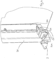
- the oven 1 comprises a frame 4 which defines a cooking chamber 3.
- the frame 4 has a front opening 46 for access to the cooking chamber 3.
- the frame 4 has a base wall 41, two side walls 42, 44, a top wall 45 and a back wall 43. As shown in the figures, the front opening 46 is located opposite to the back wall 43.
- the frame 4 also has a top opening 5 and a bottom opening 6 for air passage, whose purpose will be described in greater detail hereinbelow.
- the devices that allow operation of the oven including the heating system and/or the ventilation system (not shown) are advantageously located in the frame 4.
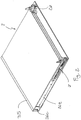
- the oven 1 further comprises a door 2, which is connected in an articulated fashion to the frame 4 and is adapted to move between an open position, to allow access to the cooking chamber 3 and a closed position, to close the front of the front opening 46 and prevent access to the cooking chamber 3.
- the door 2 is hinged at the bottom to the frame 4, in this example via articulation means, generally referenced 7.
- the door 2 comprises a support structure 21, which supports a plurality of panels, generally referenced 22.
- the plurality of panels 22 comprises an outer panel 22a, an inner panel 22d and at least one intermediate panel between the inner panel 22d and the outer panel 22a.
- the panels 22 are arranged to define respective cavities, generally referenced 23, therebetween.
- the cavity 23a is defined between the panel 22a and the panel 22b
- the cavity 23b is defined between the panel 22b and the panel 22c
- the cavity 23c is defined between the panel 22c and the panel 22d.
- the panels 22 are arranged parallel to one another and parallel to the plane defined by the support structure 21.
- the panels 22 are made of a reflective material, to reduce the absorbed amount of heat radiated by the cooking chamber 3.
- At least one of the panels 22, preferably all of them, are transparent, semi-transparent or partially transparent, for a user to see therethrough.
- the outermost panel 22a substantially defines the outer surface of the door 2 of the oven 1
- the innermost panel 22d substantially defines the inner surface of the door 2.
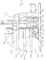
- the support structure 21 of the door 2 comprises two posts 24, 25, which define the right and left sides of the door 2; the lower side is constrained by hinges, thereby allowing the opening and closing movements of the door 2.
- each cavity 23 is defined at its sides by two posts 24, 25 of the support structure 21 and is open at its top and bottom so that, when the door 2 is in the closed position, the top and bottom openings of the cavity face the top and bottom air passage openings 5, 6 of the frame 4.
- each cavity 23 which flow enters the cavity from the bottom opening and exits the upper opening and picks up part of the heat from the panels that defines the cavity as it flows therethrough, thereby cooling them.
- a closing grid 35 extends between the two posts 24, 25, and allow air to flow into the cavities 23.
- the oven 1 comprises ventilation means 50 which can increase the air flow through each cavity 23, thereby optimizing efficiency of heat extraction from the panels 22.
- the ventilation means 50 may be located either downstream from the top opening, to suck in air therethrough and generate the air flow into the cavities 23 or upstream from the bottom opening to generate a delivery flow to the opening and into the cavities 23.
- Each of the posts 24, 25 comprises a support for one or more panels 22; particularly the two posts 24, 25 together define a support for all the intermediate panels 22b, 22c, i.e. those that define, with the outer panels 22a, 22d, the cavities 23 of the door 2.
- the post 24 may comprise seats 24a, 24b having the same size as the panels 22, and adapted to receive and support the panels 22. Opposed seats 25a, 25b are defined in the post 25.
- the seats 24a and 25a are located in the lower portion of their respective posts, and the seats 24b and 25b are located in the upper portion of their respective posts.
- the seats 24a, 24b of the post 24 are spaced from the opposed seats 25a, 25b of the post 25, at a distance that is slightly greater than the width of the intermediate panels 22b, 22c, between the two posts 24, 25, thereby allowing the intermediate panels 22b, 22c to smoothly slide in the horizontal direction X-X perpendicular to the vertical direction Y-Y.
- the intermediate panels 22b, 22c gave some clearance between the two posts 24, 25.
- the seats 24a, 24b are formed on the side of the post 24 that faces the interior of the door 2, i.e. the other post 25.
- at least one of the seats 24a (but preferably all of them) substantially has a U shape, to prevent any movement of the panel 22 except a sliding movement on its own plane.
- the post 24 comprises a longitudinal support 26 which substantially extends between the lower end and the upper end of the door 2 and a transverse support 27 which is coupled, e.g. by way of interlocking or form-fit engagement, to the longitudinal support 26, and overhangs toward the interior of the door 2 in the direction of the longitudinal support 28 and the transverse support 29 of the post 25.
- the seats 24a, 24b are formed in the transverse support 27, and the seats 25a, 25b are formed in the transverse support 29.
- the post 24 has a flat or substantially flat side facing the interior of the door 2.
- such flat side may be the inner side of the longitudinal support 26.
- each intermediate panel 22b, 22c may define a substantially continuous interface between two adjacent cavities 23. Nevertheless, it will be apparent from the above that some residual clearance may exist between each intermediate panel 22b, 22c and its posts 24, also depending on the temperature of the intermediate panel 22b, 22c and hence its expansion.
- This residual clearance may cause increased heat exchange between two adjacent cavities 23, for reasons to be further clarified below.
- a temperature-resistant sealant may be provided, or the door 2 may be designed for the influence of such heat exchange to be substantially lower than the overall heat exchange between two adjacent cavities 23.
- the residual clearance when the door 2 is at ambient temperature may be of less than about 5 mm at each side, preferably less than about 3 mm, for instance about 2 mm.
- the transverse support 27 may be made of a heat-resistant material, for instance a polymeric material, preferably reinforced with glass fibers.
- the longitudinal support 26 may be also made of a heat-resistant material, for instance of one piece with the transverse support 27, or of metal.
- the longitudinal support 26 is hollow and has an inner channel 26a open at its bottom and top and having respective bottom and top openings 26b, 26c which, with the door 2 in the closed position, face the bottom and top openings 6, 5 of the frame 4 of the oven 1 for air to flow therethrough and extract the heat absorbed by the longitudinal support 26.
- a heat insulating material may be placed in the lower portion of the door 2 between the inner panel 22 and the longitudinal support 26, to reduce the amount of heat transferred to the longitudinal support 26.
- the door 2 further comprises LED supporting means 30 connected to the support structure 21 and LED lighting means 40 mounted to the LED supporting means 30, to direct the light beam generated thereby to the interior of the cooking chamber 3, when the door 2 is in the closed position.
- the LED lighting means 40 are placed in the cavity 23a formed between the outer panel 22a and the intermediate panel 22b adjacent to the outer panel 22a.
- the particular configuration of the cavities 23, particularly the cavity 23a allows the heat radiated by the cooking chamber 3 to be effectively removed from the panels 22 and the chamber 23a to reach temperatures of less than 80°C, and be thus able to accommodate LED lighting means having commercially available LEDs.
- the LED supporting means 30 are connected to the longitudinal support 26 and include an angular structure 31 having a portion 32 for attachment to the longitudinal support 26 and a portion 33 for supporting the LED lighting means 40.
- the angular structure 31 extends parallel to the longitudinal support 26 in the direction Y-Y along at least one portion of the length of the longitudinal support 26.
- the LED lighting means 40 are arranged along the angular structure 31 over a portion thereof, particularly to about 75% of the longitudinal length of the longitudinal support 26.
- the LED lighting means 40 should not be located in the upper portion of the longitudinal support 26, where heat cannot be effectively removed.
- the angular structure 31 has a substantially triangular shape, with a first side defining the attachment portion 31, arranged parallel to the inner side of the longitudinal support 26, a second side defining the support portion 32, which is inclined relative to the first side to direct the light beam generated by the LED lighting means 40 to the interior of the cooking chamber 3 when the door 2 is in the closed position, and a third side that connects the two sides 31, 32 and is placed parallel to the panel 22a,
- the LED supporting means 30 and the LED lighting means 40 are in such positions that, when the door 2 is in the closed position, they are at least partially external to an ideal extension of the cooking chamber 3 beyond the front opening 43.
- the LED supporting means 30 and the LED lighting means 40 are in such positions that the heat radiated from the cooking chamber 3 only partially impinges upon them.
Description
- The present invention relates to an oven with an improved lighting system.
- Particularly, the present invention finds application in pyrolytic ovens.
- Pyrolytic ovens are known in the art. In this particular type of ovens, an interior cleaning cycle may be initiated, which utilizes high temperature to reduce any organic residue in the cooking chamber of the oven.
- The maximum temperatures attained during a cleaning cycle may exceed 450 °C. Therefore all the components in the proximity of the cooking chamber of the oven are exposed to high thermal stress.
- Interior lighting is also a common feature of ovens, as it allows constant monitoring of food cooking degree.
- A third common need is related to power savings, which has caused LEDs to become increasingly popular as lighting devices. An example of a traditional oven using LEDs for lighting the cooking chamber is given by document
EP 2336644 . - Nevertheless, LEDs have a poor resistance to high temperatures: therefore, LEDs have never been used instead of normal incandescent lamps (which can withstand temperatures even higher than those reached inside ovens) that have been hitherto used for interior lighting of pyrolytic ovens.
- In view of the above prior art, the object of the present invention is to provide an oven having a LED lighting device.
- Furthermore, the present invention affords advantages in terms of simple fabrication, greater strength, more compact design and/or higher versatility.
- According to the present invention, this object is fulfilled by an oven as defined in claim 1.
- The characteristics and advantages of the present invention will appear from the following detailed description of one practical embodiment, which is illustrated without limitation in the annexed drawings, in which:
-
Figure 1 is a diagrammatic view of the door of an oven of the present invention, -
Figure 2 shows another diagrammatic view of the door ofFigure 1 . -
Figure 3 is a sectional view of the door ofFigure 1 , -
Figures 4 and5 show further diagrammatic views of the door ofFigure 1 , -
Figure 6 is a view of an oven of the present invention with the door being omitted, -
Figure 7 is a view of the oven ofFigure 6 , with the door in the open position. - Although this is not expressly shown, the individual features described with reference to each embodiment shall be intended as auxiliary and/or interchangeable with other features, as described with reference to other embodiments.
- As used herein, the directions "up/down", "forward/backward", "left/right", in pairs and individually, are related to a user in front of the oven, in an ordinary position of use thereof.
- Referring to the figures, numeral 1 generally designates an oven of the present invention. In one aspect of the invention, the oven 1 may be a pyrolytic oven.
- The oven 1 comprises a frame 4 which defines a
cooking chamber 3. The frame 4 has a front opening 46 for access to thecooking chamber 3. - In accordance with one embodiment, the frame 4 has a base wall 41, two
side walls 42, 44, atop wall 45 and aback wall 43. As shown in the figures, the front opening 46 is located opposite to theback wall 43. - The frame 4 also has a top opening 5 and a bottom opening 6 for air passage, whose purpose will be described in greater detail hereinbelow.
- The devices that allow operation of the oven, including the heating system and/or the ventilation system (not shown) are advantageously located in the frame 4.
- The oven 1 further comprises a
door 2, which is connected in an articulated fashion to the frame 4 and is adapted to move between an open position, to allow access to thecooking chamber 3 and a closed position, to close the front of the front opening 46 and prevent access to thecooking chamber 3. - According to one embodiment, the
door 2 is hinged at the bottom to the frame 4, in this example via articulation means, generally referenced 7. - The
door 2 comprises asupport structure 21, which supports a plurality of panels, generally referenced 22. Particularly, the plurality ofpanels 22 comprises an outer panel 22a, aninner panel 22d and at least one intermediate panel between theinner panel 22d and the outer panel 22a. In this example, there are two intermediate panels, referenced 22b and 22c. - In a pyrolytic oven, there are advantageously two intermediate panels.
- The
panels 22 are arranged to define respective cavities, generally referenced 23, therebetween. In this example, the cavity 23a is defined between the panel 22a and thepanel 22b, thecavity 23b is defined between thepanel 22b and thepanel 22c, and the cavity 23c is defined between thepanel 22c and thepanel 22d. - In this example, the
panels 22 are arranged parallel to one another and parallel to the plane defined by thesupport structure 21. - Advantageously, the
panels 22 are made of a reflective material, to reduce the absorbed amount of heat radiated by thecooking chamber 3. - In one embodiment, at least one of the
panels 22, preferably all of them, are transparent, semi-transparent or partially transparent, for a user to see therethrough. - Generally, the outermost panel 22a substantially defines the outer surface of the
door 2 of the oven 1, and theinnermost panel 22d substantially defines the inner surface of thedoor 2. - The
support structure 21 of thedoor 2 comprises twoposts door 2; the lower side is constrained by hinges, thereby allowing the opening and closing movements of thedoor 2. - Therefore, each cavity 23 is defined at its sides by two
posts support structure 21 and is open at its top and bottom so that, when thedoor 2 is in the closed position, the top and bottom openings of the cavity face the top and bottomair passage openings 5, 6 of the frame 4. - Thus, an air flow is created in each cavity 23, which flow enters the cavity from the bottom opening and exits the upper opening and picks up part of the heat from the panels that defines the cavity as it flows therethrough, thereby cooling them.
- At the top, a
closing grid 35 extends between the twoposts - In one embodiment, the oven 1 comprises ventilation means 50 which can increase the air flow through each cavity 23, thereby optimizing efficiency of heat extraction from the
panels 22. - The ventilation means 50 may be located either downstream from the top opening, to suck in air therethrough and generate the air flow into the cavities 23 or upstream from the bottom opening to generate a delivery flow to the opening and into the cavities 23.
- Each of the
posts more panels 22; particularly the twoposts intermediate panels outer panels 22a, 22d, the cavities 23 of thedoor 2. - For example, the
post 24 may comprise seats 24a, 24b having the same size as thepanels 22, and adapted to receive and support thepanels 22. Opposed seats 25a, 25b are defined in thepost 25. - In this example, the seats 24a and 25a are located in the lower portion of their respective posts, and the seats 24b and 25b are located in the upper portion of their respective posts.
- In order to avoid failures caused by internal stresses generated by failed compensation for any thermal expansion, the seats 24a, 24b of the
post 24 are spaced from the opposed seats 25a, 25b of thepost 25, at a distance that is slightly greater than the width of theintermediate panels posts intermediate panels intermediate panels posts - As shown, the seats 24a, 24b are formed on the side of the
post 24 that faces the interior of thedoor 2, i.e. theother post 25. Preferably, at least one of the seats 24a (but preferably all of them) substantially has a U shape, to prevent any movement of thepanel 22 except a sliding movement on its own plane. - The
post 24 comprises alongitudinal support 26 which substantially extends between the lower end and the upper end of thedoor 2 and atransverse support 27 which is coupled, e.g. by way of interlocking or form-fit engagement, to thelongitudinal support 26, and overhangs toward the interior of thedoor 2 in the direction of thelongitudinal support 28 and thetransverse support 29 of thepost 25. - The seats 24a, 24b are formed in the
transverse support 27, and the seats 25a, 25b are formed in thetransverse support 29. - Advantageously, the
post 24 has a flat or substantially flat side facing the interior of thedoor 2. For instance, such flat side may be the inner side of thelongitudinal support 26. - Thus, each
intermediate panel intermediate panel posts 24, also depending on the temperature of theintermediate panel - This residual clearance may cause increased heat exchange between two adjacent cavities 23, for reasons to be further clarified below.
- In view of further decreasing heat exchange, a temperature-resistant sealant may be provided, or the
door 2 may be designed for the influence of such heat exchange to be substantially lower than the overall heat exchange between two adjacent cavities 23. - For example, the residual clearance when the
door 2 is at ambient temperature may be of less than about 5 mm at each side, preferably less than about 3 mm, for instance about 2 mm. - The
transverse support 27 may be made of a heat-resistant material, for instance a polymeric material, preferably reinforced with glass fibers. - The
longitudinal support 26 may be also made of a heat-resistant material, for instance of one piece with thetransverse support 27, or of metal. According to the invention, thelongitudinal support 26 is hollow and has aninner channel 26a open at its bottom and top and having respective bottom andtop openings 26b, 26c which, with thedoor 2 in the closed position, face the bottom andtop openings 6, 5 of the frame 4 of the oven 1 for air to flow therethrough and extract the heat absorbed by thelongitudinal support 26. - If the
longitudinal support 26 is made of metal, a heat insulating material may be placed in the lower portion of thedoor 2 between theinner panel 22 and thelongitudinal support 26, to reduce the amount of heat transferred to thelongitudinal support 26. - The
door 2 further comprises LED supporting means 30 connected to thesupport structure 21 and LED lighting means 40 mounted to the LED supporting means 30, to direct the light beam generated thereby to the interior of thecooking chamber 3, when thedoor 2 is in the closed position. The LED lighting means 40 are placed in the cavity 23a formed between the outer panel 22a and theintermediate panel 22b adjacent to the outer panel 22a. The particular configuration of the cavities 23, particularly the cavity 23a, allows the heat radiated by thecooking chamber 3 to be effectively removed from thepanels 22 and the chamber 23a to reach temperatures of less than 80°C, and be thus able to accommodate LED lighting means having commercially available LEDs. According to the invention, the LED supporting means 30 are connected to thelongitudinal support 26 and include anangular structure 31 having a portion 32 for attachment to thelongitudinal support 26 and aportion 33 for supporting the LED lighting means 40. - The
angular structure 31 extends parallel to thelongitudinal support 26 in the direction Y-Y along at least one portion of the length of thelongitudinal support 26. - Advantageously, the LED lighting means 40 are arranged along the
angular structure 31 over a portion thereof, particularly to about 75% of the longitudinal length of thelongitudinal support 26. The LED lighting means 40 should not be located in the upper portion of thelongitudinal support 26, where heat cannot be effectively removed. - In this example, the
angular structure 31 has a substantially triangular shape, with a first side defining theattachment portion 31, arranged parallel to the inner side of thelongitudinal support 26, a second side defining the support portion 32, which is inclined relative to the first side to direct the light beam generated by the LED lighting means 40 to the interior of thecooking chamber 3 when thedoor 2 is in the closed position, and a third side that connects the twosides 31, 32 and is placed parallel to the panel 22a, - In one embodiment, the LED supporting means 30 and the LED lighting means 40 are in such positions that, when the
door 2 is in the closed position, they are at least partially external to an ideal extension of thecooking chamber 3 beyond thefront opening 43. Thus, the LED supporting means 30 and the LED lighting means 40 are in such positions that the heat radiated from thecooking chamber 3 only partially impinges upon them.
Claims (8)
- An oven (1) comprising:- a frame (4) defining a cooking chamber (3), said frame (4) having a front opening (46) for access to the cooking chamber (3) and a top opening (5) and a bottom opening (4) for air passage,- a door (2), which is mounted in an articulated manner to said frame (4) and is adapted to move between an open position, to allow access to the cooking chamber (3) and a closed position, to close the front opening (46) and prevent access to the cooking chamber (3),
wherein said door (2) comprises a support structure (21) which supports an outer panel (22a), an inner panel (22d) and at least one intermediate panel (22b, 22c) between the outer panel (22a) and the inner panel (22d), said panels (22a-22d) being so arranged as to define respective cavities (23a, 23b, 23c) therebetween, each cavity being defined laterally by the support structure (21) and being open at its top and bottom so that, when the door (2) is in the closed position, the top and bottom openings of the cavity face the top and bottom air passage openings (5, 6) of the frame (4),- LED supporting means (30) connected to the support structure (21),- LED lighting means (40) mounted to the LED supporting means (30) to direct the light beam generated thereby to the cooking chamber (3), when the door (2) is in the closed position, wherein the LED lighting means (40) are placed in the cavity (23a) formed between the outer panel (22a) and the intermediate panel (22b) adjacent to the outer panel (22a),- said support structure (21) comprises two posts (24, 25), each cavity being defined at its sides by said two posts (24, 25), each post (24, 25) comprising respective opposed seats (24a, 24b, 25a, 25b) for receiving and supporting the panels,- each post (24, 25) comprises a longitudinal support (26, 28) which substantially extends between the lower end and the upper end of the door (2) and a transverse support (27, 29) which is coupled to the longitudinal support (26, 28), and overhangs toward the interior of the door (2) in the direction of the longitudinal support (28) and the transverse support of the other post, said seats (24a, 24b, 25a, 25b) being formed in their respective transverse supports (27, 29),- said longitudinal support (26, 28) is hollow and has an inner channel (26a) open at its top and its bottom, with respective top and bottom openings (26b, 26c) which, when the door (2) is in the closed position, face the top (5) and bottom (6) openings of the frame (4),characterized in that said LED supporting means (30) are connected to the longitudinal support (26) and comprise an angular structure (31) having a portion (32) for attachment to the longitudinal support (26) and a portion (33) for supporting the LED lighting means (40). - An oven as claimed in claim 1, wherein the seats (24a, 24b) of a post (24) are spaced from the opposite seats (25a, 25b) of the other post (25) at a distance slightly larger than the width of the intermediate panels (22b, 22c) between the two posts (24 25), so that the intermediate panels (22b, 22c) have some clearance between the two posts (24, 25).
- An oven as claimed in claim 2, wherein said intermediate panels (22b, 22c) have a clearance of less than about 5 mm at each side, preferably less than about 3 mm, more preferably about 2 mm, at ambient temperature.
- An oven as claimed in claim 1, wherein said angular structure (31) extends parallel to the longitudinal support (26) along at least one portion of the length of the longitudinal support (26).
- An oven as claimed in claim 1 or 2, wherein said LED lighting means (40) are arranged along the angular structure (31) over a portion of said angular structure (31).
- An oven as claimed in any claim from 2 to 5, wherein said angular structure (31) has a substantially triangular shape, with a first side defining the attachment portion (31), arranged parallel to an inner side of the longitudinal support (26), a second side defining the support portion (32), which is inclined relative to the first side to direct the light beam generated by the LED lighting means (40) to the interior of the cooking chamber (3) when the door (2) is in the closed position, and a third side that connects the first and second sides (31, 32) and is placed parallel to the outer panel (22a).
- An oven as claimed in any claim from 1 to 6, wherein said LED supporting means (30) and said LED lighting means (40) are in such arrangement that, when the door (2) is in the closed position, they are at least partially external to an ideal extension of the cooking chamber (3) beyond the front opening (43).
- An oven as claimed in any claim from 1 to 7, wherein ventilation means (50) are placed in such an arrangement as to suck in air through said top opening (5) of the frame (4) or to blow air through said bottom opening (6) of the frame (4) to increase the air flow through each cavity (23)
Priority Applications (2)
| Application Number | Priority Date | Filing Date | Title |
|---|---|---|---|
| EP12425075.4A EP2653786B1 (en) | 2012-04-20 | 2012-04-20 | Oven with lighting system |
| ES12425075.4T ES2636412T3 (en) | 2012-04-20 | 2012-04-20 | Oven with lighting system |
Applications Claiming Priority (1)
| Application Number | Priority Date | Filing Date | Title |
|---|---|---|---|
| EP12425075.4A EP2653786B1 (en) | 2012-04-20 | 2012-04-20 | Oven with lighting system |
Publications (2)
| Publication Number | Publication Date |
|---|---|
| EP2653786A1 EP2653786A1 (en) | 2013-10-23 |
| EP2653786B1 true EP2653786B1 (en) | 2017-07-05 |
Family
ID=46298340
Family Applications (1)
| Application Number | Title | Priority Date | Filing Date |
|---|---|---|---|
| EP12425075.4A Active EP2653786B1 (en) | 2012-04-20 | 2012-04-20 | Oven with lighting system |
Country Status (2)
| Country | Link |
|---|---|
| EP (1) | EP2653786B1 (en) |
| ES (1) | ES2636412T3 (en) |
Cited By (2)
| Publication number | Priority date | Publication date | Assignee | Title |
|---|---|---|---|---|
| US11022322B2 (en) | 2019-01-04 | 2021-06-01 | Whirlpool Corporation | Cooking appliance with an imaging device |
| US11287140B2 (en) | 2019-01-04 | 2022-03-29 | Whirlpool Corporation | Cooking appliance with an imaging device |
Families Citing this family (2)
| Publication number | Priority date | Publication date | Assignee | Title |
|---|---|---|---|---|
| ITUB20155043A1 (en) * | 2015-10-19 | 2017-04-19 | Piron S R L | OVEN FOR COOKING FOOD PRODUCTS |
| KR102493915B1 (en) | 2016-06-03 | 2023-02-01 | 삼성전자주식회사 | Oven |
Family Cites Families (3)
| Publication number | Priority date | Publication date | Assignee | Title |
|---|---|---|---|---|
| FR2906872B1 (en) * | 2006-10-05 | 2015-05-08 | Brandt Ind | COOKING OVEN COMPRISING AN AIR DEFLECTION DEVICE. |
| EP1995522B1 (en) * | 2007-05-25 | 2011-01-05 | Candy S.p.A. | Oven |
| ITTO20090999A1 (en) * | 2009-12-17 | 2011-06-18 | Indesit Co Spa | LIGHTING SYSTEM FOR A DOMESTIC OVEN AND TO A OVEN PROVIDED WITH SUCH A LIGHTING SYSTEM |
-
2012
- 2012-04-20 ES ES12425075.4T patent/ES2636412T3/en active Active
- 2012-04-20 EP EP12425075.4A patent/EP2653786B1/en active Active
Cited By (3)
| Publication number | Priority date | Publication date | Assignee | Title |
|---|---|---|---|---|
| US11022322B2 (en) | 2019-01-04 | 2021-06-01 | Whirlpool Corporation | Cooking appliance with an imaging device |
| US11287140B2 (en) | 2019-01-04 | 2022-03-29 | Whirlpool Corporation | Cooking appliance with an imaging device |
| US11686477B2 (en) | 2019-01-04 | 2023-06-27 | Whirlpool Corporation | Cooking appliance with an imaging device |
Also Published As
| Publication number | Publication date |
|---|---|
| EP2653786A1 (en) | 2013-10-23 |
| ES2636412T3 (en) | 2017-10-05 |
Similar Documents
| Publication | Publication Date | Title |
|---|---|---|
| EP2653786B1 (en) | Oven with lighting system | |
| US7228857B2 (en) | Electric oven with door cooling structure | |
| US8277065B2 (en) | Illumination system for cavities | |
| CN107752793B (en) | Domestic oven with muffle furnace lighting device | |
| CN102808568B (en) | Electric oven furnace door structure with heat-insulating wall technology | |
| CN107692860A (en) | Cooker | |
| CN101392923B (en) | Microwave oven with a heat exchanger | |
| CN101392924B (en) | Microwave oven | |
| KR100717437B1 (en) | Cooling structure of electric oven's door | |
| EP2333424B1 (en) | A vented oven door for a domestic cooking oven | |
| CN201641690U (en) | Door assembly of electric oven | |
| CN207720461U (en) | A kind of electromagnetic oven | |
| EP2715238A1 (en) | An oven with a cooled lighting device | |
| US8487224B2 (en) | Microwave oven | |
| CN208124852U (en) | A kind of Muffle furnace to be radiated by Air spacing pocket | |
| CN214124369U (en) | Switch cabinet structure | |
| CN203029017U (en) | Combined oven radiating system | |
| CN205878263U (en) | Electric appliance for cooking | |
| CN108036594A (en) | A kind of combined type baking oven for being used to produce coil of strip | |
| EP4317799A1 (en) | Cooking appliance | |
| KR20240018270A (en) | Cooking appliance | |
| CN1862111A (en) | Hot air convection roasting microwave oven | |
| KR20240018272A (en) | Cooking appliance | |
| KR20240018268A (en) | Cooking appliance | |
| KR20240018271A (en) | Cooking appliance |
Legal Events
| Date | Code | Title | Description |
|---|---|---|---|
| PUAI | Public reference made under article 153(3) epc to a published international application that has entered the european phase |
Free format text: ORIGINAL CODE: 0009012 |
|
| 17P | Request for examination filed |
Effective date: 20121227 |
|
| AK | Designated contracting states |
Kind code of ref document: A1 Designated state(s): AL AT BE BG CH CY CZ DE DK EE ES FI FR GB GR HR HU IE IS IT LI LT LU LV MC MK MT NL NO PL PT RO RS SE SI SK SM TR |
|
| AX | Request for extension of the european patent |
Extension state: BA ME |
|
| RIC1 | Information provided on ipc code assigned before grant |
Ipc: F24C 15/04 20060101ALI20150302BHEP Ipc: F24C 15/00 20060101AFI20150302BHEP |
|
| 17Q | First examination report despatched |
Effective date: 20150610 |
|
| GRAP | Despatch of communication of intention to grant a patent |
Free format text: ORIGINAL CODE: EPIDOSNIGR1 |
|
| INTG | Intention to grant announced |
Effective date: 20170125 |
|
| GRAS | Grant fee paid |
Free format text: ORIGINAL CODE: EPIDOSNIGR3 |
|
| GRAA | (expected) grant |
Free format text: ORIGINAL CODE: 0009210 |
|
| AK | Designated contracting states |
Kind code of ref document: B1 Designated state(s): AL AT BE BG CH CY CZ DE DK EE ES FI FR GB GR HR HU IE IS IT LI LT LU LV MC MK MT NL NO PL PT RO RS SE SI SK SM TR |
|
| REG | Reference to a national code |
Ref country code: GB Ref legal event code: FG4D |
|
| REG | Reference to a national code |
Ref country code: CH Ref legal event code: EP |
|
| REG | Reference to a national code |
Ref country code: AT Ref legal event code: REF Ref document number: 906860 Country of ref document: AT Kind code of ref document: T Effective date: 20170715 |
|
| REG | Reference to a national code |
Ref country code: IE Ref legal event code: FG4D |
|
| REG | Reference to a national code |
Ref country code: DE Ref legal event code: R096 Ref document number: 602012034152 Country of ref document: DE |
|
| REG | Reference to a national code |
Ref country code: ES Ref legal event code: FG2A Ref document number: 2636412 Country of ref document: ES Kind code of ref document: T3 Effective date: 20171005 |
|
| REG | Reference to a national code |
Ref country code: NL Ref legal event code: MP Effective date: 20170705 |
|
| REG | Reference to a national code |
Ref country code: AT Ref legal event code: MK05 Ref document number: 906860 Country of ref document: AT Kind code of ref document: T Effective date: 20170705 |
|
| REG | Reference to a national code |
Ref country code: LT Ref legal event code: MG4D |
|
| PG25 | Lapsed in a contracting state [announced via postgrant information from national office to epo] |
Ref country code: FI Free format text: LAPSE BECAUSE OF FAILURE TO SUBMIT A TRANSLATION OF THE DESCRIPTION OR TO PAY THE FEE WITHIN THE PRESCRIBED TIME-LIMIT Effective date: 20170705 Ref country code: LT Free format text: LAPSE BECAUSE OF FAILURE TO SUBMIT A TRANSLATION OF THE DESCRIPTION OR TO PAY THE FEE WITHIN THE PRESCRIBED TIME-LIMIT Effective date: 20170705 Ref country code: AT Free format text: LAPSE BECAUSE OF FAILURE TO SUBMIT A TRANSLATION OF THE DESCRIPTION OR TO PAY THE FEE WITHIN THE PRESCRIBED TIME-LIMIT Effective date: 20170705 Ref country code: NO Free format text: LAPSE BECAUSE OF FAILURE TO SUBMIT A TRANSLATION OF THE DESCRIPTION OR TO PAY THE FEE WITHIN THE PRESCRIBED TIME-LIMIT Effective date: 20171005 Ref country code: NL Free format text: LAPSE BECAUSE OF FAILURE TO SUBMIT A TRANSLATION OF THE DESCRIPTION OR TO PAY THE FEE WITHIN THE PRESCRIBED TIME-LIMIT Effective date: 20170705 Ref country code: SE Free format text: LAPSE BECAUSE OF FAILURE TO SUBMIT A TRANSLATION OF THE DESCRIPTION OR TO PAY THE FEE WITHIN THE PRESCRIBED TIME-LIMIT Effective date: 20170705 Ref country code: HR Free format text: LAPSE BECAUSE OF FAILURE TO SUBMIT A TRANSLATION OF THE DESCRIPTION OR TO PAY THE FEE WITHIN THE PRESCRIBED TIME-LIMIT Effective date: 20170705 |
|
| PG25 | Lapsed in a contracting state [announced via postgrant information from national office to epo] |
Ref country code: RS Free format text: LAPSE BECAUSE OF FAILURE TO SUBMIT A TRANSLATION OF THE DESCRIPTION OR TO PAY THE FEE WITHIN THE PRESCRIBED TIME-LIMIT Effective date: 20170705 Ref country code: IS Free format text: LAPSE BECAUSE OF FAILURE TO SUBMIT A TRANSLATION OF THE DESCRIPTION OR TO PAY THE FEE WITHIN THE PRESCRIBED TIME-LIMIT Effective date: 20171105 Ref country code: PL Free format text: LAPSE BECAUSE OF FAILURE TO SUBMIT A TRANSLATION OF THE DESCRIPTION OR TO PAY THE FEE WITHIN THE PRESCRIBED TIME-LIMIT Effective date: 20170705 Ref country code: GR Free format text: LAPSE BECAUSE OF FAILURE TO SUBMIT A TRANSLATION OF THE DESCRIPTION OR TO PAY THE FEE WITHIN THE PRESCRIBED TIME-LIMIT Effective date: 20171006 Ref country code: BG Free format text: LAPSE BECAUSE OF FAILURE TO SUBMIT A TRANSLATION OF THE DESCRIPTION OR TO PAY THE FEE WITHIN THE PRESCRIBED TIME-LIMIT Effective date: 20171005 Ref country code: LV Free format text: LAPSE BECAUSE OF FAILURE TO SUBMIT A TRANSLATION OF THE DESCRIPTION OR TO PAY THE FEE WITHIN THE PRESCRIBED TIME-LIMIT Effective date: 20170705 |
|
| REG | Reference to a national code |
Ref country code: DE Ref legal event code: R097 Ref document number: 602012034152 Country of ref document: DE |
|
| PG25 | Lapsed in a contracting state [announced via postgrant information from national office to epo] |
Ref country code: DK Free format text: LAPSE BECAUSE OF FAILURE TO SUBMIT A TRANSLATION OF THE DESCRIPTION OR TO PAY THE FEE WITHIN THE PRESCRIBED TIME-LIMIT Effective date: 20170705 Ref country code: RO Free format text: LAPSE BECAUSE OF FAILURE TO SUBMIT A TRANSLATION OF THE DESCRIPTION OR TO PAY THE FEE WITHIN THE PRESCRIBED TIME-LIMIT Effective date: 20170705 Ref country code: CZ Free format text: LAPSE BECAUSE OF FAILURE TO SUBMIT A TRANSLATION OF THE DESCRIPTION OR TO PAY THE FEE WITHIN THE PRESCRIBED TIME-LIMIT Effective date: 20170705 |
|
| REG | Reference to a national code |
Ref country code: FR Ref legal event code: PLFP Year of fee payment: 7 |
|
| PLBE | No opposition filed within time limit |
Free format text: ORIGINAL CODE: 0009261 |
|
| STAA | Information on the status of an ep patent application or granted ep patent |
Free format text: STATUS: NO OPPOSITION FILED WITHIN TIME LIMIT |
|
| PG25 | Lapsed in a contracting state [announced via postgrant information from national office to epo] |
Ref country code: EE Free format text: LAPSE BECAUSE OF FAILURE TO SUBMIT A TRANSLATION OF THE DESCRIPTION OR TO PAY THE FEE WITHIN THE PRESCRIBED TIME-LIMIT Effective date: 20170705 Ref country code: SM Free format text: LAPSE BECAUSE OF FAILURE TO SUBMIT A TRANSLATION OF THE DESCRIPTION OR TO PAY THE FEE WITHIN THE PRESCRIBED TIME-LIMIT Effective date: 20170705 Ref country code: SK Free format text: LAPSE BECAUSE OF FAILURE TO SUBMIT A TRANSLATION OF THE DESCRIPTION OR TO PAY THE FEE WITHIN THE PRESCRIBED TIME-LIMIT Effective date: 20170705 |
|
| 26N | No opposition filed |
Effective date: 20180406 |
|
| PG25 | Lapsed in a contracting state [announced via postgrant information from national office to epo] |
Ref country code: SI Free format text: LAPSE BECAUSE OF FAILURE TO SUBMIT A TRANSLATION OF THE DESCRIPTION OR TO PAY THE FEE WITHIN THE PRESCRIBED TIME-LIMIT Effective date: 20170705 |
|
| PG25 | Lapsed in a contracting state [announced via postgrant information from national office to epo] |
Ref country code: MC Free format text: LAPSE BECAUSE OF FAILURE TO SUBMIT A TRANSLATION OF THE DESCRIPTION OR TO PAY THE FEE WITHIN THE PRESCRIBED TIME-LIMIT Effective date: 20170705 |
|
| REG | Reference to a national code |
Ref country code: CH Ref legal event code: PL |
|
| REG | Reference to a national code |
Ref country code: BE Ref legal event code: MM Effective date: 20180430 |
|
| REG | Reference to a national code |
Ref country code: IE Ref legal event code: MM4A |
|
| PG25 | Lapsed in a contracting state [announced via postgrant information from national office to epo] |
Ref country code: LU Free format text: LAPSE BECAUSE OF NON-PAYMENT OF DUE FEES Effective date: 20180420 |
|
| PG25 | Lapsed in a contracting state [announced via postgrant information from national office to epo] |
Ref country code: CH Free format text: LAPSE BECAUSE OF NON-PAYMENT OF DUE FEES Effective date: 20180430 Ref country code: LI Free format text: LAPSE BECAUSE OF NON-PAYMENT OF DUE FEES Effective date: 20180430 Ref country code: BE Free format text: LAPSE BECAUSE OF NON-PAYMENT OF DUE FEES Effective date: 20180430 |
|
| PG25 | Lapsed in a contracting state [announced via postgrant information from national office to epo] |
Ref country code: IE Free format text: LAPSE BECAUSE OF NON-PAYMENT OF DUE FEES Effective date: 20180420 |
|
| PG25 | Lapsed in a contracting state [announced via postgrant information from national office to epo] |
Ref country code: MT Free format text: LAPSE BECAUSE OF NON-PAYMENT OF DUE FEES Effective date: 20180420 |
|
| PG25 | Lapsed in a contracting state [announced via postgrant information from national office to epo] |
Ref country code: PT Free format text: LAPSE BECAUSE OF FAILURE TO SUBMIT A TRANSLATION OF THE DESCRIPTION OR TO PAY THE FEE WITHIN THE PRESCRIBED TIME-LIMIT Effective date: 20170705 Ref country code: HU Free format text: LAPSE BECAUSE OF FAILURE TO SUBMIT A TRANSLATION OF THE DESCRIPTION OR TO PAY THE FEE WITHIN THE PRESCRIBED TIME-LIMIT; INVALID AB INITIO Effective date: 20120420 |
|
| PG25 | Lapsed in a contracting state [announced via postgrant information from national office to epo] |
Ref country code: CY Free format text: LAPSE BECAUSE OF FAILURE TO SUBMIT A TRANSLATION OF THE DESCRIPTION OR TO PAY THE FEE WITHIN THE PRESCRIBED TIME-LIMIT Effective date: 20170705 Ref country code: MK Free format text: LAPSE BECAUSE OF NON-PAYMENT OF DUE FEES Effective date: 20170705 |
|
| PG25 | Lapsed in a contracting state [announced via postgrant information from national office to epo] |
Ref country code: AL Free format text: LAPSE BECAUSE OF FAILURE TO SUBMIT A TRANSLATION OF THE DESCRIPTION OR TO PAY THE FEE WITHIN THE PRESCRIBED TIME-LIMIT Effective date: 20170705 |
|
| PGFP | Annual fee paid to national office [announced via postgrant information from national office to epo] |
Ref country code: IT Payment date: 20230306 Year of fee payment: 12 |
|
| PGFP | Annual fee paid to national office [announced via postgrant information from national office to epo] |
Ref country code: FR Payment date: 20230425 Year of fee payment: 12 Ref country code: ES Payment date: 20230503 Year of fee payment: 12 Ref country code: DE Payment date: 20230420 Year of fee payment: 12 |
|
| PGFP | Annual fee paid to national office [announced via postgrant information from national office to epo] |
Ref country code: TR Payment date: 20230417 Year of fee payment: 12 |
|
| PGFP | Annual fee paid to national office [announced via postgrant information from national office to epo] |
Ref country code: GB Payment date: 20230419 Year of fee payment: 12 |