EP2653763B1 - Electromagnetic valve for a container valve of a fuel supply system - Google Patents
Electromagnetic valve for a container valve of a fuel supply system Download PDFInfo
- Publication number
- EP2653763B1 EP2653763B1 EP13160009.0A EP13160009A EP2653763B1 EP 2653763 B1 EP2653763 B1 EP 2653763B1 EP 13160009 A EP13160009 A EP 13160009A EP 2653763 B1 EP2653763 B1 EP 2653763B1
- Authority
- EP
- European Patent Office
- Prior art keywords
- electromagnetic valve
- valve
- armature
- seal
- pilot
- Prior art date
- Legal status (The legal status is an assumption and is not a legal conclusion. Google has not performed a legal analysis and makes no representation as to the accuracy of the status listed.)
- Active
Links
Images


Classifications
-
- F—MECHANICAL ENGINEERING; LIGHTING; HEATING; WEAPONS; BLASTING
- F16—ENGINEERING ELEMENTS AND UNITS; GENERAL MEASURES FOR PRODUCING AND MAINTAINING EFFECTIVE FUNCTIONING OF MACHINES OR INSTALLATIONS; THERMAL INSULATION IN GENERAL
- F16K—VALVES; TAPS; COCKS; ACTUATING-FLOATS; DEVICES FOR VENTING OR AERATING
- F16K31/00—Actuating devices; Operating means; Releasing devices
- F16K31/02—Actuating devices; Operating means; Releasing devices electric; magnetic
- F16K31/06—Actuating devices; Operating means; Releasing devices electric; magnetic using a magnet, e.g. diaphragm valves, cutting off by means of a liquid
- F16K31/0675—Electromagnet aspects, e.g. electric supply therefor
-
- F—MECHANICAL ENGINEERING; LIGHTING; HEATING; WEAPONS; BLASTING
- F02—COMBUSTION ENGINES; HOT-GAS OR COMBUSTION-PRODUCT ENGINE PLANTS
- F02M—SUPPLYING COMBUSTION ENGINES IN GENERAL WITH COMBUSTIBLE MIXTURES OR CONSTITUENTS THEREOF
- F02M21/00—Apparatus for supplying engines with non-liquid fuels, e.g. gaseous fuels stored in liquid form
- F02M21/02—Apparatus for supplying engines with non-liquid fuels, e.g. gaseous fuels stored in liquid form for gaseous fuels
-
- F—MECHANICAL ENGINEERING; LIGHTING; HEATING; WEAPONS; BLASTING
- F02—COMBUSTION ENGINES; HOT-GAS OR COMBUSTION-PRODUCT ENGINE PLANTS
- F02D—CONTROLLING COMBUSTION ENGINES
- F02D19/00—Controlling engines characterised by their use of non-liquid fuels, pluralities of fuels, or non-fuel substances added to the combustible mixtures
- F02D19/02—Controlling engines characterised by their use of non-liquid fuels, pluralities of fuels, or non-fuel substances added to the combustible mixtures peculiar to engines working with gaseous fuels
-
- F—MECHANICAL ENGINEERING; LIGHTING; HEATING; WEAPONS; BLASTING
- F16—ENGINEERING ELEMENTS AND UNITS; GENERAL MEASURES FOR PRODUCING AND MAINTAINING EFFECTIVE FUNCTIONING OF MACHINES OR INSTALLATIONS; THERMAL INSULATION IN GENERAL
- F16K—VALVES; TAPS; COCKS; ACTUATING-FLOATS; DEVICES FOR VENTING OR AERATING
- F16K27/00—Construction of housing; Use of materials therefor
- F16K27/02—Construction of housing; Use of materials therefor of lift valves
- F16K27/029—Electromagnetically actuated valves
-
- F—MECHANICAL ENGINEERING; LIGHTING; HEATING; WEAPONS; BLASTING
- F16—ENGINEERING ELEMENTS AND UNITS; GENERAL MEASURES FOR PRODUCING AND MAINTAINING EFFECTIVE FUNCTIONING OF MACHINES OR INSTALLATIONS; THERMAL INSULATION IN GENERAL
- F16K—VALVES; TAPS; COCKS; ACTUATING-FLOATS; DEVICES FOR VENTING OR AERATING
- F16K31/00—Actuating devices; Operating means; Releasing devices
- F16K31/02—Actuating devices; Operating means; Releasing devices electric; magnetic
- F16K31/06—Actuating devices; Operating means; Releasing devices electric; magnetic using a magnet, e.g. diaphragm valves, cutting off by means of a liquid
- F16K31/0644—One-way valve
- F16K31/0651—One-way valve the fluid passing through the solenoid coil
-
- F—MECHANICAL ENGINEERING; LIGHTING; HEATING; WEAPONS; BLASTING
- F16—ENGINEERING ELEMENTS AND UNITS; GENERAL MEASURES FOR PRODUCING AND MAINTAINING EFFECTIVE FUNCTIONING OF MACHINES OR INSTALLATIONS; THERMAL INSULATION IN GENERAL
- F16K—VALVES; TAPS; COCKS; ACTUATING-FLOATS; DEVICES FOR VENTING OR AERATING
- F16K31/00—Actuating devices; Operating means; Releasing devices
- F16K31/02—Actuating devices; Operating means; Releasing devices electric; magnetic
- F16K31/06—Actuating devices; Operating means; Releasing devices electric; magnetic using a magnet, e.g. diaphragm valves, cutting off by means of a liquid
- F16K31/0644—One-way valve
- F16K31/0655—Lift valves
-
- F—MECHANICAL ENGINEERING; LIGHTING; HEATING; WEAPONS; BLASTING
- F16—ENGINEERING ELEMENTS AND UNITS; GENERAL MEASURES FOR PRODUCING AND MAINTAINING EFFECTIVE FUNCTIONING OF MACHINES OR INSTALLATIONS; THERMAL INSULATION IN GENERAL
- F16K—VALVES; TAPS; COCKS; ACTUATING-FLOATS; DEVICES FOR VENTING OR AERATING
- F16K39/00—Devices for relieving the pressure on the sealing faces
- F16K39/02—Devices for relieving the pressure on the sealing faces for lift valves
- F16K39/024—Devices for relieving the pressure on the sealing faces for lift valves using an auxiliary valve on the main valve
-
- F—MECHANICAL ENGINEERING; LIGHTING; HEATING; WEAPONS; BLASTING
- F02—COMBUSTION ENGINES; HOT-GAS OR COMBUSTION-PRODUCT ENGINE PLANTS
- F02M—SUPPLYING COMBUSTION ENGINES IN GENERAL WITH COMBUSTIBLE MIXTURES OR CONSTITUENTS THEREOF
- F02M21/00—Apparatus for supplying engines with non-liquid fuels, e.g. gaseous fuels stored in liquid form
- F02M21/02—Apparatus for supplying engines with non-liquid fuels, e.g. gaseous fuels stored in liquid form for gaseous fuels
- F02M21/0218—Details on the gaseous fuel supply system, e.g. tanks, valves, pipes, pumps, rails, injectors or mixers
- F02M21/0221—Fuel storage reservoirs, e.g. cryogenic tanks
-
- F—MECHANICAL ENGINEERING; LIGHTING; HEATING; WEAPONS; BLASTING
- F02—COMBUSTION ENGINES; HOT-GAS OR COMBUSTION-PRODUCT ENGINE PLANTS
- F02M—SUPPLYING COMBUSTION ENGINES IN GENERAL WITH COMBUSTIBLE MIXTURES OR CONSTITUENTS THEREOF
- F02M21/00—Apparatus for supplying engines with non-liquid fuels, e.g. gaseous fuels stored in liquid form
- F02M21/02—Apparatus for supplying engines with non-liquid fuels, e.g. gaseous fuels stored in liquid form for gaseous fuels
- F02M21/0218—Details on the gaseous fuel supply system, e.g. tanks, valves, pipes, pumps, rails, injectors or mixers
- F02M21/023—Valves; Pressure or flow regulators in the fuel supply or return system
- F02M21/0242—Shut-off valves; Check valves; Safety valves; Pressure relief valves
-
- F—MECHANICAL ENGINEERING; LIGHTING; HEATING; WEAPONS; BLASTING
- F16—ENGINEERING ELEMENTS AND UNITS; GENERAL MEASURES FOR PRODUCING AND MAINTAINING EFFECTIVE FUNCTIONING OF MACHINES OR INSTALLATIONS; THERMAL INSULATION IN GENERAL
- F16K—VALVES; TAPS; COCKS; ACTUATING-FLOATS; DEVICES FOR VENTING OR AERATING
- F16K31/00—Actuating devices; Operating means; Releasing devices
- F16K31/02—Actuating devices; Operating means; Releasing devices electric; magnetic
- F16K31/06—Actuating devices; Operating means; Releasing devices electric; magnetic using a magnet, e.g. diaphragm valves, cutting off by means of a liquid
- F16K31/0644—One-way valve
- F16K31/0655—Lift valves
- F16K31/0658—Armature and valve member being one single element
-
- Y—GENERAL TAGGING OF NEW TECHNOLOGICAL DEVELOPMENTS; GENERAL TAGGING OF CROSS-SECTIONAL TECHNOLOGIES SPANNING OVER SEVERAL SECTIONS OF THE IPC; TECHNICAL SUBJECTS COVERED BY FORMER USPC CROSS-REFERENCE ART COLLECTIONS [XRACs] AND DIGESTS
- Y02—TECHNOLOGIES OR APPLICATIONS FOR MITIGATION OR ADAPTATION AGAINST CLIMATE CHANGE
- Y02E—REDUCTION OF GREENHOUSE GAS [GHG] EMISSIONS, RELATED TO ENERGY GENERATION, TRANSMISSION OR DISTRIBUTION
- Y02E60/00—Enabling technologies; Technologies with a potential or indirect contribution to GHG emissions mitigation
- Y02E60/30—Hydrogen technology
- Y02E60/32—Hydrogen storage
-
- Y—GENERAL TAGGING OF NEW TECHNOLOGICAL DEVELOPMENTS; GENERAL TAGGING OF CROSS-SECTIONAL TECHNOLOGIES SPANNING OVER SEVERAL SECTIONS OF THE IPC; TECHNICAL SUBJECTS COVERED BY FORMER USPC CROSS-REFERENCE ART COLLECTIONS [XRACs] AND DIGESTS
- Y02—TECHNOLOGIES OR APPLICATIONS FOR MITIGATION OR ADAPTATION AGAINST CLIMATE CHANGE
- Y02T—CLIMATE CHANGE MITIGATION TECHNOLOGIES RELATED TO TRANSPORTATION
- Y02T10/00—Road transport of goods or passengers
- Y02T10/10—Internal combustion engine [ICE] based vehicles
- Y02T10/30—Use of alternative fuels, e.g. biofuels
Definitions
- the present invention relates to an electromagnetic valve for a reservoir valve of a fuel supply system for supplying a gaseous fuel to a storage container and for supplying a consumer with gaseous fuel from this storage container.
- the present invention further relates to such a container valve and a fuel supply system with such an electromagnetic valve.
- the electromagnetic valve controls the gas flow during refueling and driving and is an essential part of a container valve
- the additional security elements such as overpressure protection and / or thermal fuse to secure the storage container against impermissibly high pressures or fire, flow restrictor to protect against excessive gas flows after external component break, switching elements such as manual shut-off valve to prevent gas flow, service valve for manual emptying of the storage container, additional elements such as filter element to protect the switching elements from contamination, check valve for Druclcines, temperature sensor for measuring the gas temperature in the container, and the like. contains and meets high safety requirements with external force.
- document CA 2 802 182 A1 discloses a valve main body provided in a housing included in a magnetic on-off valve.
- a pre-opening is formed on the valve main body, and a pre-valve body is inserted in the pre-opening so as to open and close the pre-opening.
- the pilot valve body and the main valve body move in accordance with the movement of a valve piston which is movable in an opening direction.
- the valve piston and the pilot valve body are coupled together by a coupling pin inserted through the valve piston and the pilot valve body.
- the coupling pin is provided to be displaceable relative to the pilot valve body.
- valve piston stops the movement of the main valve body relative to the valve piston in the opening direction.
- WO 2010/029359 A1 discloses an electronically operable valve assembly including a valve member including a ferromagnetic member and a magnetic circuit configured to conduct magnetic flux through the ferromagnetic member when the valve member is disposed separate from its valve seat to hold the primary valve open.
- the electromagnetic valve for a reservoir valve of a fuel supply system of a gas-fuel vehicle comprises a magnet coil with an internal yoke and a magnet armature, which is axially movable in the inner yoke.
- the armature consists of an armature, a sealing element, which is arranged between the armature and a fuel inlet, and a counter-pole, which rests on the sealing element.
- the magnet coil preferably comprises a fastening component, the inner yoke, an outer yoke and a termination.
- the electromagnetic valve preferably further comprises an elastic element, which presses the armature against the sealing element and the sealing element against a sealing surface in non-energized magnetic coil.
- the object is achieved by way of example by a housing-less pilot-operated electromagnetic valve with a movable opposite pole, the displaceable armature consists only of sealing element, armature and opposite pole, which is guided by the inner conclusion of the magnetic coil, the opposite pole on the Sealing element abuts and the armature, which is preferably at least partially covered by the sealing element, the first working gap for opening the pilot hole by lifting the armature of the pilot control, and the opposite pole in the axial direction to the inner conclusion the second working gap for opening the inlet by lifting the Forms sealing element of the main sealing surface.
- the pilot stroke for opening the pilot bore is independent of the main stroke for opening the main bore, so that a small electrical power is required with the small first working gap to open the pilot bore and a large flow cross-section with low throttle losses is achieved with the large second working gap , Due to the direct guidance of the armature in the inner conclusion of the magnetic coil, which leads the magnetic field targeted to or from the armature, the power consumption of the electromagnetic valve is further reduced.
- the electromagnetic valve By installing the electromagnetic valve in the high-pressure chamber of the storage container is dispensed with a pressure-bearing housing, which facilitates the spread of the magnetic field, and yet the protection of external force and against improper manipulation ensured.
- the simple design of the magnet armature consisting of three parts (armature, sealing element, counter-pole) and the associated pressure-bearing housing reduces the weight and cost of the electromagnetic valve.
- the solenoid and the magnet armature are preferably arranged so that upon activation of the solenoid first a pilot port for the fuel by moving the armature in the direction of the opposite pole and by detachment of the armature is opened by the sealing element, and subsequently a main opening for the fuel by moving the Magnetic armature in the direction of completion of the solenoid coil and is opened by detachment of the sealing element from the fuel inlet.
- the first working gap is preferably smaller than the second working gap, so that the first working gap is for example between 50 and 0.5% and more preferably between 25 and 0.01% of the length of the second working gap.
- the pilot control opening preferably has a smaller flow cross section than the main opening, the preferably between 25 and 0.05% and more preferably between 15 and 1% of the flow cross-section of the main opening.
- the present invention further relates to such a container valve and a fuel supply system with such an electromagnetic valve.
- the present invention further relates to a flow restrictor for such a fuel supply system of a valve body with an integrated filter element.
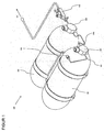
- a fuel supply system 100 for the supply of a consumer 101, with gaseous fuel such as natural gas, methane, biogas, hydrogen or the like one or more storage containers 102 with container valve 103 and electromagnetic valve 200, which in the refueling over a filling side arranged filling coupling 104 with integrated non-return valve and filter and an adjoining gas supply line 105 are supplied with fuel gas and the consumer 101 via a control unit 106, consisting at least of a pressure regulator, which reduces the pressure of the stored gas from the accumulator pressure to the working pressure with fuel gas provided.
- a control unit 106 consisting at least of a pressure regulator, which reduces the pressure of the stored gas from the accumulator pressure to the working pressure with fuel gas provided.
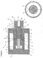
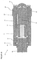
- the electromagnetic valve 200 comprises a multi-part magnet armature 201, a multi-part magnet coil 202 and preferably a spring as an elastic element 203 for closing or releasing the inlet 208c against the high-pressure space 102a of the storage tank 102.
- the magnet armature 201 comprises a Sealing element 204 of a suitable sealing material with a main sealing surface 204a for sealing against the sealing surface 208d of the valve attachment 208, a pilot control sealing surface 204b for sealing against the associated Vor Kunststoffdicht Chemistry 205a of the armature 205, and a bore 204c between Vor faceddicht Chemistry 204b and Hauptdicht Chemistry 204a and a support 204d for support the counterpole 206 on the sealing element 204, a magnetizable armature 205 with a pilot control sealing surface 205a for sealing against the associated pilot control sealing surface 204b and grooves 205b for receiving the support 204d, a magnetizable n movable counter-pole 206 which bears against the support 204d, with an inner bore 206a for receiving the elastic element 203.
- the elastic element 203 pushes the armature 205 against the sealing element 204 and the sealing element 204 against the sealing surface 208d and closes when not energized energized solenoid 202, the flow path between the inlet 208c and the high-pressure chamber 102a of the storage container 102.
- the magnet coil 202 comprises a multi-part inner yoke 207 comprising a magnetizable valve mount 208 with a suitable fastening thread 208a for fastening the electromagnetic valve 200 in the housing of the container valve 103, a groove 208b for receiving a suitable seal for sealing the high-pressure chamber 102a to the inlet 208c, a sealing surface 208d for sealing against the associated main sealing surface 204a and flow paths 208e to the high-pressure chamber 102a of the storage container 102, a non-magnetic spacer 209 for guiding the magnetic field and a magnetizable termination 210.
- the magnetic coil 202 further comprises an overmolded magnet winding 211 from a winding body 212 for receiving a winding (copper wire ) and a magnetizable outer conclusion 214 for connecting the individual parts of the solenoid coil 202 and the electromagnetic valve 200th
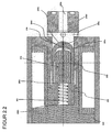
- Fig. 2.1 is shown at the beginning of the removal by energizing the solenoid 202, a magnetic field over the magnetizable parts of the armature 201, the working gap 205c, the magnetizable parts of the inner yoke 207 and the outer yoke 214 of the magnetic coil 202 constructed.
- the armature 205 is pulled against the force of the elastic element 203 to the opposite pole 206, which is supported on the sealing element 204, and lifts the pilot control sealing surface 205a from the associated pilot control sealing surface 204b.
- High-pressure gas from the region of the counter-pole 206 can flow out into the inlet 208c until the pressure equalization via the released pilot-control bore 204c.
- the magnetic field in the electromagnetic valve 200 is reduced and the elastic member 203 shifts the armature 205 with the sealing member 204 in the closing position according to Fig. 3 , And the opposite pole 206 is taken by the remaining magnetic forces in the closed position.
- the closing effect is amplified when the bore 204c is closed by the pressure difference built up over the magnet armature 201.
- the electromagnetic valve 300 comprises a valve mount 308 having flow paths 308e for guiding the flow in the valve mount 308, a valve plug 310 having flow paths 310a for guiding the flow in the valve plug 310 opening into a flow path 310b, and a bobbin with input-side header 312a, flow path 312b, and output-side header 312c.
- the electromagnetic valve 300 When the electromagnetic valve 300 is open, the high-pressure gas flows from the inlet 308c via the flow paths 308e, 312a, 312b, 312c, 310a and 310b into the high-pressure space 102a of the storage container 102.
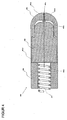
- a magnet armature 400 comprises a sealing element 401 of a suitable sealing compound having a main sealing surface 401a for sealing against the associated sealing surface 208d of the solenoid 202, a pilot sealing surface 401b for sealing against the associated pilot sealing surface 402a of the armature 402, a bore 401c Pre-control sealing surface 402a and main sealing surface 401a and a support 401d for supporting the Jacobpoles 406 on the sealing element 401, and a magnetizable armature 402 with a pilot control sealing surface 402a for sealing against the associated Vor Kunststoffdicht Structure 401b, and a magnetizable movable counter-pole 406 which abuts the support 401d, with an inner bore 406a for receiving the elastic element 203rd
- a magnetic armature 500 comprises a sealing element 501 of a suitable sealing material having a main sealing surface 501a for sealing against the associated sealing surface 208d of the solenoid 202, a pilot sealing surface 501b for sealing against the associated pilot control sealing surface 502a of the armature 502, a bore 501c Main sealing surface 502a and pilot control sealing surface 502b and a projection 501d for receiving in the support 504, a support 504 for receiving the sealing element 501 and supporting the Jacobpoles 506 and a magnetizable armature 502 with a pilot control sealing surface 502a to seal against the associated Vor Kunststoffdicht Structure 501b, and a magnetizable movable Counter pole 506, which bears against the support 504, with an inner bore 506a for receiving the elastic element 203rd
- a force-controlled armature 600 includes a sealing member 601 of a suitable sealing material having a main sealing surface 601a for sealing against the associated sealing surface 208d of the solenoid 202, a pilot sealing surface 601b for sealing against the associated pilot sealing surface 602a of the armature 602, a bore 601c between main sealing surface 601a and pilot control sealing surface 601b, a support 601d for supporting the counter-pole 606 on the sealing element 601 and a driver 601e for entrainment by the counter pole 603, and a magnetizable armature 602 with a pilot sealing surface 602a for sealing against the associated pilot control sealing surface 601b, and a magnetizable movable Gegenpol 606, which bears against the support 601d, with an inner bore 606c for receiving the elastic element 203 and a driver 606b for driving the sealing element 601. Between the sealing element 601 and the Martinezpol 606 is the first working gap 602c and the Mituring
- the sealing element 601 Due to the positive control via the driver 601e and 606b, the sealing element 601 is lifted in addition to the pressure forces on the individual parts of the armature 600 by the existing magnetic force of the associated sealing surface 208c.
- the invention further comprises an electrical feedthrough with a projection with electrical pins with a sealing geometry comprising different diameters.
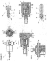
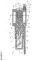
- the container valve 700 comprises a housing 701 with a fastening thread 702 for fastening the container valve 700 in a suitable receptacle of the storage container 102 and a groove 703 for receiving a suitable seal 704 for sealing the high-pressure space 102a of the storage container 102 from the environment with the high-pressure connections 706a and 706b with threaded ports 707a and 707b and sealing grooves 708a and 708b for receiving a suitable seal 709a and 709b for direct connection of the high pressure lines and sealing the flow path 710a against the environment with subsequent flow path 710b and fuel inlet 710c between the inlets 706a, 706b and the high pressure space 102a the storage container 102 with the intermediate opening 711 with associated fastening thread 711a, sealing surface 711b, sealing surface 711c and groove 7
- a second embodiment for the housing 801 of the container valve 800 includes a groove 803 for a radial sealing gasket 804 and receives the electromagnetic valve Fig. 2
- the flow restrictor 815 comprises, analogously to the flow restrictor 715, a valve body 815a with an opening 815e for receiving the filter 816.
- the non-return spring 815c of the flow restrictor 815 rests against the fuse 818 of the termination 310.
- the housing 901 of the container valve 900 in another embodiment comprises a groove 903 for a seal 904 at the transition of the thread to the protruding from the storage container housing part.
- the electromagnetic valve 200 includes a Groove 911b to guide the flow.
- the disc-shaped flow restrictor 915 is held in position via a spring member 915c supporting a suitable groove 915d of the flow restrictor 915 and seals with the sealing surface 915b against the associated sealing surface 911d of the valve attachment 208 as needed.
- the electrical connector plug 924 comprises in a further embodiment the electrical feedthrough 922, which is formed with a groove 922i and receives the seal 922d, which seals against the associated sealing surface 921b of the joint 920b.
- the electrical connector is held by a retaining ring 925 in a suitable groove of the housing 901.
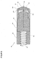
- the electromagnetic valve 1000 comprises a multi-part magnet armature 1001 as described above and a multi-part pressure-tight housing 1002 for the internal container or container valve external housing, comprising a housing 1003 for axially movable guidance of the magnet armature 1001 and a sealing magnetisablecondition 1008.
- the housing 1003 comprises a suitable mounting thread 1004 for valve mounting in the container valve 103 and a groove 1005 for receiving a suitable sealing ring for sealing the drucltbelasteten valve interior to the container valve 103 and a receiving bore 1006 with support 1007 for supporting the conclusion 1008 and sealing groove 1009 for receiving a suitable seal for sealing against the associated Sealing surface of the conclusion 1008.
- the housing 1003 may be a non-magnetizable housing.
- the thin-walled pressure-bearing housing 1003 comprises for pressure maintenance and conduction of the magnetic field a magnetizable first reinforcement 1010, a non-magnetizable second reinforcement 1011 and a magnetizable third reinforcement 1012, each of which may be on the outside.
- the first reinforcement 1010, the third reinforcement 1012 and the termination 1009 are in communication with the conclusion of the magnetic coil and conduct the magnetic field to and from the armature 1001.
- the refueling via the control unit can take place.
- the filling coupling can be arranged directly on the container valve
- the electromagnetic valve can be pressed with the housing of the container valve.
- the sealing element of the electromagnetic valve can seal to a suitable sealing surface of the housing of the container valve.
- a suitable seal for reducing the leakage current between valve attachment and sealing element can be installed on the sealing element of the magnet armature.
- a second elastic element which is supported on the opposite pole and presses the opposite pole against the sealing element, are installed.
- the flow paths of the closure to the flow restrictor can be made axially parallel.
- the intermediate piece of the magnetic coil can be omitted.
- the winding body of the magnetic coil can be executed without webs.
- the magnetic coil can be encapsulated on the outside.
- the housing of the container valve can be designed with a suitable threaded threaded fitting for connecting the high pressure lines.
- the housing of the container valve can be executed with a HochdruclcanNot.
- the mechanical shut-off valve can be designed in several parts with a suitable sealing element to complete the flow path.
- the housing of the container valve can be designed with its own connection for a safety line for the removal of the storage gas after release of the flow path through the thermal fuse.
- the housing of the container valve can be designed with a fastening thread and a suitable sealing surface for the installation of an external thermal fuse as a closed screw-in part.
- the electrical feedthrough can be implemented as a separate part.
- the pins of the electrical can be performed without sealing geometry.
- the pins of the electrical feedthrough can be pressed in.
- the electrical leads of the temperature sensor and the magnet winding without pin are led directly through the electrical feedthrough.
- a loose cable with attached electrical connector can be performed for external signal forwarding.
- the flow restrictor may be implemented as a separate part which is suitably connected to the output of the electromagnetic valve.
- the flow restrictor is positioned by means of a spring.
- the filter may be implemented as a separate part which is suitably connected to the output of the electromagnetic valve.
- the individual elements can be positioned reversed in the direction of flow.
- the completion of the pressure-bearing valve housing can be fastened with a fastening thread in the housing and / or comprise the sealing groove.
- the pressure-bearing valve housing comprises a magnetizable first reinforcement and a non-magnetizable second reinforcement.
Description
Die vorliegende Erfindung betrifft ein elektromagnetisches Ventil für ein Behälterventil einer Kraftstoffversorgungsanlage zum Zuführen eines gasförmigen Kraftstoffes zu einem Speicherbehälter und zur Versorgung eines Verbrauchers mit gasförmigem Kraftstoff aus diesem Speicherbehälter. Die vorliegende Erfindung betrifft weiterhin ein solches Behälterventil und eine Kraftstoffversorgungsanlage mit einem solchen elektromagnetischen Ventil.The present invention relates to an electromagnetic valve for a reservoir valve of a fuel supply system for supplying a gaseous fuel to a storage container and for supplying a consumer with gaseous fuel from this storage container. The present invention further relates to such a container valve and a fuel supply system with such an electromagnetic valve.
Alternative gasförmige Energieträger wie Erdgas, Methan, Biogas und Wasserstoff gewinnen im Verkehrswesen aufgrund ihres CO2-Einsparpotentials und aus Gründen der Versorgungssicherheit zunehmend an Bedeutung. Diese Energieträger werden zur Erzielung der geforderten Reichweiten typischerweise in komprimierter Form in Druckzylindern bei Nenndrücken von bis zu 700 bar gespeichert und dem Verbraucher bei einem Arbeitsdruck von ca. 10 bar zur Verfügung gestellt.Alternative gaseous energy sources such as natural gas, methane, biogas and hydrogen are becoming increasingly important in the transport sector due to their potential for saving CO 2 and for reasons of security of supply. These energy sources are typically stored in compressed cylinders in compressed cylinders at nominal pressures of up to 700 bar to achieve the required ranges and made available to the consumer at a working pressure of about 10 bar.
Das elektromagnetische Ventil steuert die Gasströmung bei der Betankung und im Fahrbetrieb und ist ein wesentlicher Bestandteil eines Behälterventiles, das zusätzlich Sicherungselemente wie z.B. Überdrucksicherung und/oder Thermische Sicherung zur Sicherung des Speicherbehälters vor unzulässig hohen Drücken oder Feuereinwirkung, Durchflussbegrenzer zum Schutz vor unzulässig großen Gasströmen nach externem Bauteilbruch, Schaltelemente wie z.B. manuelles Absperrventil zur Unterbindung der Gasströmung, Serviceventil zum manuellen Entleeren des Speicherbehälters, Zusatzelemente wie z.B. Filterelement zum Schutz der Schaltelemente vor Verschmutzung, Rückschlagventil zur Druclchaltung, Temperatursensor zur Messung der Gastemperatur im Behälter, u.dgl. enthält und hohe Sicherheitsanforderungen bei äußerer Krafteinwirkung erfüllt.The electromagnetic valve controls the gas flow during refueling and driving and is an essential part of a container valve, the additional security elements such as overpressure protection and / or thermal fuse to secure the storage container against impermissibly high pressures or fire, flow restrictor to protect against excessive gas flows after external component break, switching elements such as manual shut-off valve to prevent gas flow, service valve for manual emptying of the storage container, additional elements such as filter element to protect the switching elements from contamination, check valve for Druclchaltung, temperature sensor for measuring the gas temperature in the container, and the like. contains and meets high safety requirements with external force.
Dem Fachmann sind unterschiedliche Ausführungsformen von elektromagnetischen Ventilen bekannt, deren Funktionsweise und Anordnung die Form und Größe des Behälterventiles bestimmt.The person skilled in various embodiments of electromagnetic valves are known whose operation and arrangement determines the shape and size of the container valve.
Aus der
Aus der
Aus der
Dokument
Dokument
Die vorliegende Erfindung stellt sich die Aufgabe, die Nachteile des Standes der Technik zu vermeiden und ein elektromagnetisches Ventil bzw. ein Behälterventil in kompakter und einfacher Bauweise zu schaffen, das unter anderem einige oder alle folgenden Vorteile aufweist:
- Kompakte Bauform und geringe Leistungsaufnahme des elektromagnetischen Ventiles durch gewähltes Funktionsprinzip
- Einfacher Aufbau des elektromagnetischen Ventiles durch geringe Bauteilanzahl
- Schutz bei äußerer Krafteinwirkung und gegen unsachgemäße Manipulation durch Anordnung des elektromagnetischen Ventiles im Inneren des Speicherbehälters
- Kompakte Bauform des Behälterventiles mit einfachem Bohrbild durch Anordnung des elektromagnetischen Ventiles im Inneren des Speicherbehälters
- Compact design and low power consumption of the electromagnetic valve due to selected operating principle
- Simple design of the electromagnetic valve due to low number of components
- Protection against external forces and against improper manipulation by placing the electromagnetic valve inside the storage tank
- Compact design of the container valve with a simple hole pattern by arranging the electromagnetic valve inside the storage tank
Diese technische Aufgabe der vorliegenden Erfindung wird vom Gegenstand der unabhängigen Patentansprüche gelöst. Weitere Ausgestaltungen der Erfindung sind in den abhängigen Ansprüchen zu finden.This technical problem of the present invention is solved by the subject matter of the independent patent claims. Further embodiments of the invention can be found in the dependent claims.
Das erfindungsgemäße elektromagnetische Ventil für ein Behälterventil einer Kraftstoffversorgungsanlage eines Gaskraftfahrzeugs umfasst eine Magnetspule mit einem inneren Rückschluss und einen Magnetanker, der in dem inneren Rückschluss axial beweglich ist. Der Magnetanker besteht aus einem Anker, einem Dichtelement, welches zwischen dem Anker und einem Kraftstoffzulauf angeordnet ist, und einem Gegenpol, welches am Dichtelement anliegt.The electromagnetic valve for a reservoir valve of a fuel supply system of a gas-fuel vehicle according to the invention comprises a magnet coil with an internal yoke and a magnet armature, which is axially movable in the inner yoke. The armature consists of an armature, a sealing element, which is arranged between the armature and a fuel inlet, and a counter-pole, which rests on the sealing element.
Die Magnetspule umfasst vorzugsweise eine Befestigungskomponente, den inneren Rückschluss, einen äußeren Rückschluss und einen Abschluss. Das elektromagnetische Ventil umfasst vorzugsweise weiterhin ein elastisches Element, welches bei nicht erregter Magnetspule den Anker gegen das Dichtelement und das Dichtelement gegen eine Dichtfläche drückt.The magnet coil preferably comprises a fastening component, the inner yoke, an outer yoke and a termination. The electromagnetic valve preferably further comprises an elastic element, which presses the armature against the sealing element and the sealing element against a sealing surface in non-energized magnetic coil.
In anderen Worten, die Aufgabe wird beispielhaft durch ein gehäuseloses vorgesteuerte elektromagnetischen Ventil mit beweglichem Gegenpol gelöst, dessen verschiebbarer Magnetanker nur aus Dichtelement, Anker und Gegenpol besteht, der durch den inneren Rückschluss der Magnetspule geführt wird, wobei der Gegenpol am Dichtelement anliegt und zum Anker, der bevorzugt zumindest teilweise vom Dichtelement umfasst wird, den ersten Arbeitsspalt zum Öffnen der Vorsteuerbohrung durch Abheben des Ankers von der Vorsteuerdichtfläche bildet, und der Gegenpol in axialer Richtung zum inneren Rückschluss den zweiten Arbeitsspalt zum Öffnen des Zulaufes durch Abheben des Dichtelementes von der Hauptdichtfläche bildet.In other words, the object is achieved by way of example by a housing-less pilot-operated electromagnetic valve with a movable opposite pole, the displaceable armature consists only of sealing element, armature and opposite pole, which is guided by the inner conclusion of the magnetic coil, the opposite pole on the Sealing element abuts and the armature, which is preferably at least partially covered by the sealing element, the first working gap for opening the pilot hole by lifting the armature of the pilot control, and the opposite pole in the axial direction to the inner conclusion the second working gap for opening the inlet by lifting the Forms sealing element of the main sealing surface.
Durch die Ausführung mit beweglichem Gegenpol ist der Vorsteuerhub zum Öffnen der Vorsteuerbohrung unabhängig vom Haupthub zum Öffnen der Hauptbohrung, sodass mit dem kleinen ersten Arbeitsspalt zum Öffnen der Vorsteuerbohrung eine kleine elektrische Leistung benötigt und mit dem großen zweiten Arbeitsspalt ein großer Strömungsquerschnitt mit geringen Drosselverlusten erreicht wird. Durch die direkte Führung des Magnetankers im inneren Rückschluss der Magnetspule, der das Magnetfeld gezielt zum bzw. vom Magnetanker führt, wird die Leistungsaufnahme des elektromagnetischen Ventiles weiter verringert. Durch den Verbau des elektromagnetischen Ventiles im Hochdruckraum des Speicherbehälters wird auf ein drucktragendes Gehäuse verzichtet, was die Ausbreitung des Magnetfeldes erleichtert, und trotzdem der Schutz bei äußere Krafteinwirkung und gegen unsachgemäße Manipulation sichergestellt. Durch den einfachen Aufbau des Magnetankers aus drei Teilen (Anker, Dichtelement, Gegenpol) und das entfallende drucktragende Gehäuse werden Gewicht und Kosten des elektromagnetischen Ventiles reduziert.Due to the version with a movable counter-pole, the pilot stroke for opening the pilot bore is independent of the main stroke for opening the main bore, so that a small electrical power is required with the small first working gap to open the pilot bore and a large flow cross-section with low throttle losses is achieved with the large second working gap , Due to the direct guidance of the armature in the inner conclusion of the magnetic coil, which leads the magnetic field targeted to or from the armature, the power consumption of the electromagnetic valve is further reduced. By installing the electromagnetic valve in the high-pressure chamber of the storage container is dispensed with a pressure-bearing housing, which facilitates the spread of the magnetic field, and yet the protection of external force and against improper manipulation ensured. The simple design of the magnet armature consisting of three parts (armature, sealing element, counter-pole) and the associated pressure-bearing housing reduces the weight and cost of the electromagnetic valve.
Die Magnetspule und der Magnetanker sind bevorzugt so angeordnet, dass beim Aktivieren der Magnetspule zuerst eine Vorsteueröffnung für den Kraftstoff durch Verschieben des Ankers in Richtung des Gegenpols und durch Ablösen des Ankers von dem Dichtelement geöffnet wird, und nachfolgend eine Hauptöffnung für den Kraftstoff durch Verschieben des Magnetankers in Richtung eines Abschluss der Magnetspule und durch Ablösen des Dichtelements vom Kraftstoffzulauf geöffnet wird.The solenoid and the magnet armature are preferably arranged so that upon activation of the solenoid first a pilot port for the fuel by moving the armature in the direction of the opposite pole and by detachment of the armature is opened by the sealing element, and subsequently a main opening for the fuel by moving the Magnetic armature in the direction of completion of the solenoid coil and is opened by detachment of the sealing element from the fuel inlet.
Der erste Arbeitsspalt ist vorzugsweise kleiner als der zweite Arbeitsspalt, so dass der erste Arbeitsspalt beispielhaft zwischen 50 und 0,5 % und weiter bevorzugt zwischen 25 und 0,01 % der Länge des zweiten Arbeitsspalts beträgt. Die Vorsteueröffnung weist vorzugsweise einen kleineren Strömungsquerschnitt als die Hauptöffnung auf, der bevorzugt zwischen 25 und 0,05 % und weiter bevorzugt zwischen 15 und 1 % des Strömungsquerschnitts der Hauptöffnung liegt.The first working gap is preferably smaller than the second working gap, so that the first working gap is for example between 50 and 0.5% and more preferably between 25 and 0.01% of the length of the second working gap. The pilot control opening preferably has a smaller flow cross section than the main opening, the preferably between 25 and 0.05% and more preferably between 15 and 1% of the flow cross-section of the main opening.
Die vorliegende Erfindung betrifft weiterhin ein solches Behälterventil und eine Kraftstoffversorgungsanlage mit einem solchen elektromagnetischen Ventil. Die vorliegende Erfindung betrifft weiterhin einen Durchflussbegrenzer für eine solche Kraftstoffversorgungsanlage aus einem Ventilkörper mit einem integrierten Filterelement.The present invention further relates to such a container valve and a fuel supply system with such an electromagnetic valve. The present invention further relates to a flow restrictor for such a fuel supply system of a valve body with an integrated filter element.
Anhand der Zeichnungen werden verschiedene beispielhafte Ausführungsformen der Erfindung im Folgenden erläutert:
-
Fig. 1 zeigt schematisch eine Kraftstoffversorgungsanlage eines gasbetriebenen Kraftfahrzeuges. -
Fig. 2 zeigt ein elektromagnetisches Ventil gemäß einem ersten Ausführungsbeispiel im geschlossenen Zustand. -
Fig. 2.1 zeigt ein elektromagnetisches Ventil gemäß einem ersten Ausführungsbeispiel bei geöffneter Vorsteuerbohrung. -
Fig. 2.2 zeigt ein elektromagnetisches Ventil gemäß einem ersten Ausführungsbeispiel bei geöffnetem Zulauf. -
Fig. 3 zeigt ein elektromagnetisches Ventil gemäß einem zweiten Ausführungsbeispiel im geschlossenen Zustand. -
Fig. 4 ,5 und6 zeigen unterschiedliche Magnetanker für ein elektromagnetisches Ventil. -
Fig. 7, 7.1 und 7.2 zeigt ein Behälterventil gemäß einem ersten Ausführungsbeispiel. -
Fig. 8 zeigt ein Behälterventils gemäß einem zweiten Ausführungsbeispiel. -
Fig. 9 zeigt ein Behälterventil gemäß einem dritten Ausführungsbeispiel. -
Fig. 10 zeigt ein elektromagnetisches Ventil mit einem mehrteiligen druckdichtem Gehäuse
-
Fig. 1 schematically shows a fuel supply system of a gas-powered motor vehicle. -
Fig. 2 shows an electromagnetic valve according to a first embodiment in the closed state. -
Fig. 2.1 shows an electromagnetic valve according to a first embodiment with open pilot hole. -
Fig. 2.2 shows an electromagnetic valve according to a first embodiment with the inlet open. -
Fig. 3 shows an electromagnetic valve according to a second embodiment in the closed state. -
Fig. 4 .5 and6 show different armature for an electromagnetic valve. -
Fig. 7, 7.1 and 7.2 shows a container valve according to a first embodiment. -
Fig. 8 shows a container valve according to a second embodiment. -
Fig. 9 shows a container valve according to a third embodiment. -
Fig. 10 shows an electromagnetic valve with a multi-part pressure-tight housing
Wie in
Wie in
Wie in
Wie in
Wie in
Durch die Abschaltung des Stromes wird das magnetische Feld im elektromagnetischen Ventil 200 abgebaut und das elastische Element 203 verschiebt den Anker 205 mit dem Dichtelement 204 in die Schließposition gemäß
Wie in
Wie in
Wie in
Wie in
Durch die Zwangssteuerung über den Mitnehmer 601e und 606b wird das Dichtelement 601 zusätzlich zu den Druckkräften an den Einzelteilen des Magnetankers 600 durch die vorhandene Magnetkraft von der zugeordneten Dichtfläche 208c abgehoben.Due to the positive control via the
Die Erfindung umfasst weiterhin eine elektrische Durchführung mit einem Ansatz mit elektrischen Pins mit einer Dichtgeometrie umfassend unterschiedliche Durchmesser. Wie in
Wie in
Wie in
Wie in
In einer weiteren Ausführungsform kann die Betankung über die Regeleinheit erfolgen.In a further embodiment, the refueling via the control unit can take place.
In einer weiteren Ausführungsform kann die Befüllkupplung direkt am Behälterventil angeordnet werdenIn a further embodiment, the filling coupling can be arranged directly on the container valve
In einer weiteren Ausführungsform kann das elektromagnetische Ventil mit dem Gehäuse des Behälterventiles verpresst werden.In a further embodiment, the electromagnetic valve can be pressed with the housing of the container valve.
In einer weiteren Ausführungsform kann das Dichtelement des elektromagnetischen Ventiles zu einer geeigneten Dichtfläche des Gehäuses des Behälterventiles abdichten.In a further embodiment, the sealing element of the electromagnetic valve can seal to a suitable sealing surface of the housing of the container valve.
In einer weiteren Ausführungsform kann am Dichtelement des Magnetankers eine geeignete Dichtung zur Verkleinerung des Leckstroms zwischen Ventilbefestigung und Dichtelement verbaut werden.In a further embodiment, a suitable seal for reducing the leakage current between valve attachment and sealing element can be installed on the sealing element of the magnet armature.
In einer weiteren Ausführungsform kann ein zweites elastisches Element, dass sich am Gegenpol abstützt und den Gegenpol gegen das Dichtelement drückt, verbaut werden.In a further embodiment, a second elastic element, which is supported on the opposite pole and presses the opposite pole against the sealing element, are installed.
In einer weiteren Ausführungsform können die Strömungswege des Abschlusses zum Durchflussbegrenzer achsparallel ausgeführt werden.In a further embodiment, the flow paths of the closure to the flow restrictor can be made axially parallel.
In einer weiteren Ausführungsform kann das Zwischenstück der Magnetspule entfallen.In a further embodiment, the intermediate piece of the magnetic coil can be omitted.
In einer weiteren Ausführungsform kann der Wickelkörper der Magnetspule ohne Stege ausgeführt werden.In a further embodiment, the winding body of the magnetic coil can be executed without webs.
In einer weiteren Ausführungsform kann die Magnetspule an der Außenseite umspritzt werden.In a further embodiment, the magnetic coil can be encapsulated on the outside.
In einer weiteren Ausführungsform kann das Gehäuse des Behälterventiles mit einem geeigneten mit Gewinde befestigten Gewindefitting zum Anschluss der Hochdruckleitungen ausgeführt werden.In a further embodiment, the housing of the container valve can be designed with a suitable threaded threaded fitting for connecting the high pressure lines.
In einer weiteren Ausführungsform kann das Gehäuse des Behälterventiles mit einem Hochdruclcanschluss ausgeführt werden.In a further embodiment, the housing of the container valve can be executed with a Hochdruclcanschluss.
In einer weiteren Ausführungsform kann das Manuelle Absperrventil bei Ausführung des Gehäuses des Behälterventiles mit einemIn another embodiment, the manual shut-off valve in execution of the housing of the container valve with a
Hochdruckanschluss gegenüberliegend und parallel zum Hochdruckanschluss ausgeführt werden.High pressure connection opposite and parallel to the high pressure connection to be executed.
In einer weiteren Ausführungsform kann das Mechanische Absperrventil mehrteilig mit einem geeigneten Dichtelement zur Abschließen des Strömungsweges ausgeführt werden.In a further embodiment, the mechanical shut-off valve can be designed in several parts with a suitable sealing element to complete the flow path.
In einer weiteren Ausführungsform kann das Gehäuse des Behälterventiles mit einem eigenen Anschluss für eine Sicherheitsleitung zur Abfuhr des Speichergases nach Freigabe des Strömungsweges durch die Thermische Sicherung ausgeführt werden.In a further embodiment, the housing of the container valve can be designed with its own connection for a safety line for the removal of the storage gas after release of the flow path through the thermal fuse.
In einer weiteren Ausführungsform kann das Gehäuse des Behälterventiles mit einem Befestigungsgewinde und geeigneter Dichtfläche zum Verbau einer externen Thermischen Sicherung als geschlossener Einschraubteil ausgeführt werden.In a further embodiment, the housing of the container valve can be designed with a fastening thread and a suitable sealing surface for the installation of an external thermal fuse as a closed screw-in part.
In einer weiteren Ausführungsform kann die Elektrische Durchführung als eigener Teil ausgeführt werden.In a further embodiment, the electrical feedthrough can be implemented as a separate part.
In einer weiteren Ausführungsform können die Pins der Elektrischen ohne Dichtgeometrie ausgeführt werden.In a further embodiment, the pins of the electrical can be performed without sealing geometry.
In einer weiteren Ausführungsform können die Pins der Elektrischen Durchführung eingepresst werden.In a further embodiment, the pins of the electrical feedthrough can be pressed in.
In einer weiteren Ausführungsform werden die elektrischen Leitungen des Temperatursensors und der Magnetwicklung ohne Pin direkt durch die Elektrische Durchführung geführt.In a further embodiment, the electrical leads of the temperature sensor and the magnet winding without pin are led directly through the electrical feedthrough.
In einer weiteren Ausführungsform kann zur äußeren Signalweiterleitung ein loses Kabel mit angebautem Elektrikstecker ausgeführt werden.In a further embodiment, a loose cable with attached electrical connector can be performed for external signal forwarding.
In einer weiteren Ausführungsform kann der Durchflussbegrenzer als eigenständiger Teil ausgeführt werden, der in geeigneter Weise mit dem Ausgang des elektromagnetischen Ventiles verbunden ist.In another embodiment, the flow restrictor may be implemented as a separate part which is suitably connected to the output of the electromagnetic valve.
In einer weiteren Ausführungsform wird der Durchflussbegrenzer mit Hilfe einer Feder positioniert.In another embodiment, the flow restrictor is positioned by means of a spring.
In einer weiteren Ausführungsform kann der Filter als eigenständiger Teil ausgeführt werden, der in geeigneter Weise mit dem Ausgang des elektromagnetischen Ventiles verbunden ist.In a further embodiment, the filter may be implemented as a separate part which is suitably connected to the output of the electromagnetic valve.
In einer weiteren Ausführungsform können die einzelnen Elemente in Strömungsrichtung vertauscht positioniert werden.In a further embodiment, the individual elements can be positioned reversed in the direction of flow.
In einer weiteren Ausführungsform kann der Abschluss des drucktragenden Ventilgehäuses mit einem Befestigungsgewinde im Gehäuse befestigt werden und/oder die Dichtnut umfassen.In another embodiment, the completion of the pressure-bearing valve housing can be fastened with a fastening thread in the housing and / or comprise the sealing groove.
In einer weiteren Ausführungsform umfasst das drucktragende Ventilgehäuse eine magnetisierbare ersten Verstärkung und eine nichmagnetisierbare zweite Verstärkung.In a further embodiment, the pressure-bearing valve housing comprises a magnetizable first reinforcement and a non-magnetizable second reinforcement.
Weitere Ausführungsformen entstehen durch Kombination der angeführten Ausführungsformen.Further embodiments arise by combining the cited embodiments.
Claims (19)
- An electromagnetic valve (200) for a tank valve (103) of a fuel supply system (100) of a gas fuel motor vehicle, comprising a magnetic coil (202) with an inner guide (207); and
a magnetic armature (201) which can move axially in the inner guide (207), wherein the magnetic armature (201) consists of an armature (205), a seal element (204) which is arranged between the armature (205) and a fuel inlet (208c), and a counter pole (206) which abuts the seal element (204);
wherein the magnetic coil (202) and the magnetic armature (201) are arranged such that, when activating the magnetic coil (202), a pilot opening (204c) for a high-pressure fuel is opened by means of the armature (205) sliding in the direction of the counter pole (206) and by means of the armature (205) being released from the seal element (204), so that the high-pressure fuel from the region of the counter pole (206) flows into the gas inlet (208c) via the pilot opening (204c);
characterized in that
a primary opening for the high-pressure fuel is subsequently opened by means of the magnetic armature (201) sliding in the direction of a termination (210) of the magnetic coil (202) and by means of the seal element (204) releasing from the fuel inlet (208c) due to a pressure difference created as a result of the flow of the high-pressure fuel from the region of the counter pole (206). - The electromagnetic valve (200) according to claim 1, wherein the armature (205) and the counter pole (206) enclose a first working air gap (205c) for opening the pilot opening (220).
- The electromagnetic valve (200) according to any one of the preceding claims, wherein the counter pole (206) and the termination (210) of the magnetic coil (202) enclose a second working air gap (206b) for opening the primary opening.
- The electromagnetic valve (200) according to the preceding claim, wherein the first working air gap (206b) is smaller than the second working air gap (205c), and has a length of preferably between 50 and 0.5%, and more preferably between 25 and 0.01%, of the length of the second working air gap (205c).
- The electromagnetic valve (200) according to any one of the preceding claims, wherein the pilot opening (204c) has a smaller flow cross-section than the primary opening, which is preferably between 25 and 0.05%, and more preferably between 15 and 1% of the flow cross-section of the primary opening.
- The electromagnetic valve (200) according to any one of the preceding claims, wherein a pilot lifting movement to open the pilot opening (204c) is independent of a primary lifting movement to open the primary opening.
- The electromagnetic valve (200) according to any one of the preceding claims, wherein the magnetic coil (202) comprises a fastening component (208) within the inner guide (207), an external guide (214), and a magnetic winding (211).
- The electromagnetic valve (200) according to any one of the preceding claims, wherein the seal element (204) surrounds the armature (205) at least partially.
- The electromagnetic valve (200) according to any one of the preceding claims, wherein the seal element (204) surrounds the counter pole (206) at least partially.
- The electromagnetic valve (200) according to any one of the preceding claims, wherein the seal element (204) comprises a primary seal surface (204a) for creating a seal with a seal surface (208d) of the fastening component (208) of the guide (207), and a pilot seal surface (204b) for creating a seal with a pilot seal surface (205a) of the armature (205).
- The electromagnetic valve (200) according to any one of the preceding claims, wherein the seal element (204) has a primary seal surface (204a) for creating a seal with a seal surface (713b) of the housing (701), and a pilot seal surface (204b) for creating a seal with a pilot seal surface (205a) of the armature (205).
- The electromagnetic valve (200) according to any one of the preceding claims, wherein the seal element (204) comprises a bore hole (204c) between the pilot seal surface (204b) and the primary seal surface (204a), and a support (204d) for supporting the counter pole (206) on the seal element (204).
- The electromagnetic valve (200) according to claim 10 or claims 11 or 12, when depending from claim 10, further comprising an elastic element (203) which, when the magnetic coil (202) is not excited, presses the armature (205) against the seal element (204) and the seal element (204) against the seal surface (208d).
- The electromagnetic valve (200) according to any one of the preceding claims, further comprising an elastic element, which presses the counter pole (206) against the seal element (204).
- Tank valve (103) for a fuel supply system (100), comprising an electromagnetic valve (200) according to any one of claims 1 to 14, and in particular comprising at least one of the following elements: a manual check valve, a thermal protection, a burst protection, a manual service valve, a flow restrictor, a filter element, a temperature sensor, an electrical passage.
- A multi-part, pressure-tight housing (1002) of an electromagnetic valve (200) of a tank valve (103) according to claim 15 of a fuel supply system (100) of a gas fuel motor vehicle comprising a housing (1003) for guiding the axial movement of the magnetic armature (1001), of a magnetizable termination (1008), of a magnetizable first reinforcement (1010), of a non-magnetizable second reinforcement (1011) and of a magnetizable third reinforcement (1012), wherein the reinforcements (1010, 1011, 1012) ensure the radial pressure resistance of the housing (1002) and conduct the magnetic field to the magnetic armature (1002).
- A tank valve (103) of a fuel supply system (100), comprising an electromagnetic valve according to any one of claims 1 to 14 and wherein at least one of the following elements is integrated into the electromagnetic valve: a flow restrictor, a temperature sensor, a filter element, an electrical passage.
- A fuel supply system (100) having an electromagnetic valve (200) according to any one of claims 1 to 14, which is arranged in a high-pressure chamber (102a) of a fuel storage tank (102).
- A flow restrictor (815) of a fuel supply system (100) according to claim 18, comprising a valve body (815e) with an integrated filter element (816).
Applications Claiming Priority (1)
| Application Number | Priority Date | Filing Date | Title |
|---|---|---|---|
| DE102012206604A DE102012206604A1 (en) | 2012-04-20 | 2012-04-20 | Electromagnetic valve for a tank valve of a fuel supply system |
Publications (3)
| Publication Number | Publication Date |
|---|---|
| EP2653763A2 EP2653763A2 (en) | 2013-10-23 |
| EP2653763A3 EP2653763A3 (en) | 2014-04-30 |
| EP2653763B1 true EP2653763B1 (en) | 2016-06-08 |
Family
ID=48049766
Family Applications (1)
| Application Number | Title | Priority Date | Filing Date |
|---|---|---|---|
| EP13160009.0A Active EP2653763B1 (en) | 2012-04-20 | 2013-03-19 | Electromagnetic valve for a container valve of a fuel supply system |
Country Status (10)
| Country | Link |
|---|---|
| US (1) | US9366357B2 (en) |
| EP (1) | EP2653763B1 (en) |
| JP (1) | JP6220541B2 (en) |
| KR (1) | KR102022043B1 (en) |
| CN (1) | CN103375631B (en) |
| BR (1) | BR102013009560B1 (en) |
| CA (1) | CA2812270C (en) |
| DE (1) | DE102012206604A1 (en) |
| ES (1) | ES2590149T3 (en) |
| RU (1) | RU2644665C2 (en) |
Families Citing this family (22)
| Publication number | Priority date | Publication date | Assignee | Title |
|---|---|---|---|---|
| US8881958B2 (en) * | 2009-12-16 | 2014-11-11 | Intelligent Coffee Company, Llc | Fluid dose-measuring device |
| ITBS20130146A1 (en) * | 2013-10-18 | 2015-04-19 | Omb Saleri S P A | VALVE FOR METHANE IN AUTOMOTIVE SYSTEMS WITH BY-PASS SYSTEM OF THE BLOCK DEVICE FOR EXCESS FLOW |
| DE102014106940B4 (en) * | 2014-05-16 | 2023-08-24 | Mesa Parts GmbH | Electromagnetically operated high-pressure gas valve |
| CN104235596B (en) * | 2014-07-17 | 2016-03-30 | 上海云逸能源系统有限公司 | High pressure gas storage cryopreservation device |
| DE102015104799B4 (en) * | 2015-03-27 | 2016-10-20 | Mesa Parts GmbH | Valve arrangement, use of a valve assembly, modular system for constructing valve assemblies |
| LU92718B1 (en) * | 2015-05-13 | 2016-11-14 | Luxembourg Patent Co | Electromagnetic valve with magnetically actuated main and pilot valve elements |
| CN107850230B (en) * | 2015-07-15 | 2019-03-08 | 日产自动车株式会社 | Valve gear |
| PL3205935T3 (en) * | 2016-02-11 | 2019-11-29 | Copreci S Coop | Gas appliance comprising a gas cock and a control device |
| US10753498B2 (en) * | 2018-01-25 | 2020-08-25 | Mac Valves, Inc. | Flow-through liquid valve |
| US10539250B2 (en) * | 2018-04-24 | 2020-01-21 | Honeywell International Inc. | High vibration, high cycle, pulse width modulated solenoid |
| DE102018215380A1 (en) | 2018-09-11 | 2020-03-12 | Robert Bosch Gmbh | Valve device for a gaseous medium and tank device for storing a gaseous medium |
| DE102018217044A1 (en) * | 2018-10-04 | 2020-04-09 | Volkswagen Aktiengesellschaft | Internal combustion engine and method for operating an internal combustion engine |
| CN110065386B (en) * | 2019-05-24 | 2024-02-06 | 武汉格罗夫氢能汽车有限公司 | Highly integrated hydrogen cylinder group structure of passenger car |
| AT16929U1 (en) * | 2019-05-28 | 2020-12-15 | Zieger Dipl Ing Andreas | Combination valve |
| AT17317U1 (en) * | 2019-09-03 | 2021-12-15 | Andreas Zieger Dipl Ing | pressure control valve |
| DE102020200679A1 (en) * | 2020-01-22 | 2021-07-22 | Robert Bosch Gesellschaft mit beschränkter Haftung | Method for opening a valve assembly for a fuel tank |
| DE102020203700A1 (en) * | 2020-03-23 | 2021-09-23 | Robert Bosch Gesellschaft mit beschränkter Haftung | Valve device for a fuel cell system and tank device for storing a gaseous medium |
| AT524094B1 (en) * | 2020-08-04 | 2022-05-15 | Andreas Zieger Dipl Ing | Electromagnetically operated valve |
| KR20220129734A (en) * | 2021-03-17 | 2022-09-26 | 현대자동차주식회사 | Valve for hydrogen tank of fuel cell vehicle |
| DE102022208071A1 (en) * | 2022-08-03 | 2024-02-08 | Robert Bosch Gesellschaft mit beschränkter Haftung | Shut-off valve for a fuel gas tank, fuel gas tank with shut-off valve and fuel gas tank system |
| DE102022209914A1 (en) | 2022-09-21 | 2024-03-21 | Robert Bosch Gesellschaft mit beschränkter Haftung | Valve assembly for a fuel gas tank, fuel gas tank with valve assembly and fuel gas tank system |
| CN115451327B (en) * | 2022-10-10 | 2023-08-15 | 南通大学 | Liquefied natural gas holding vessel sealing head |
Family Cites Families (24)
| Publication number | Priority date | Publication date | Assignee | Title |
|---|---|---|---|---|
| US2914086A (en) * | 1954-11-16 | 1959-11-24 | Controls Co Of America | Valve device |
| US3405906A (en) * | 1966-08-04 | 1968-10-15 | Itt | Solenoid pilot operated valve |
| US3872878A (en) * | 1973-12-17 | 1975-03-25 | Controls Co Of America | Anti-contaminant diaphragm valve |
| CH591038A5 (en) * | 1975-06-27 | 1977-08-31 | Lucifer Sa | |
| US4248270A (en) * | 1980-01-11 | 1981-02-03 | The Singer Company | Reduced noise water valve provided with flow control |
| US4500067A (en) * | 1983-02-07 | 1985-02-19 | Eaton Corporation | Pilot operated low flow valve |
| DE3934953A1 (en) * | 1989-10-20 | 1991-04-25 | Bosch Gmbh Robert | SOLENOID VALVE, ESPECIALLY FOR FUEL INJECTION PUMPS |
| US5209265A (en) * | 1990-04-14 | 1993-05-11 | Matsushita Electric Works, Ltd. | Flow control device with restrictor |
| US5188017A (en) | 1991-06-18 | 1993-02-23 | The Consumers' Gas Company, Ltd. | Natural gas cylinder fitting and solenoid valve |
| US5205531A (en) * | 1992-04-09 | 1993-04-27 | Sterling Hydraulics, Inc. | Solenoid operated cartridge valve |
| US5452738A (en) * | 1994-02-22 | 1995-09-26 | Amcast Industrial Corporation | Crashworthy solenoid actuated valve for CNG powered vehicle |
| JPH09508338A (en) * | 1994-11-24 | 1997-08-26 | ローベルト ボツシユ ゲゼルシヤフト ミツト ベシユレンクテル ハフツング | Electromagnetically controllable valve device |
| DE19531010B4 (en) * | 1995-08-23 | 2004-04-29 | Robert Bosch Gmbh | Solenoid valve, in particular for a slip-controlled, hydraulic brake system for motor vehicles |
| US5820102A (en) * | 1996-10-15 | 1998-10-13 | Superior Valve Company | Pressurized fluid storge and transfer system including a sonic nozzle |
| US5813652A (en) * | 1996-10-22 | 1998-09-29 | Emerson Electric Co. | Apparatus for suppressing noise generated by a flow of water through a water valve |
| CA2312186A1 (en) | 2000-06-23 | 2001-12-23 | Erick Girouard | Crashproof instant-on tank valve |
| CA2333241A1 (en) * | 2001-01-30 | 2002-07-30 | Russell H. Barton | Coupling mechanism and valve system for a pressurized fluid container |
| DE10361781B4 (en) | 2003-10-21 | 2005-09-15 | Klaus Dipl.-Ing. Perthel | Electromagnetic valve for vehicle gas cylinders has externally threaded casing which screws into cylinder ands has central bore, in which piston and electromagnetic controls are mounted which are fitted through top of bore |
| US7481412B2 (en) * | 2004-11-30 | 2009-01-27 | Keihin Corporation | Solenoid-operated cutoff valve for use with fuel cells |
| JP4696758B2 (en) * | 2005-07-28 | 2011-06-08 | トヨタ自動車株式会社 | Fuel storage tank, fuel cell system, mobile object |
| US8066256B2 (en) * | 2008-02-01 | 2011-11-29 | Danfoss A/S | Valve actuator assembly |
| RU2482370C2 (en) * | 2008-09-09 | 2013-05-20 | Артемис Интеллиджент Пауэр Лимитед | Valve assembly |
| JP5498269B2 (en) * | 2010-06-15 | 2014-05-21 | 川崎重工業株式会社 | Solenoid open / close valve |
| DE102010026548A1 (en) * | 2010-07-08 | 2012-01-12 | Magna Steyr Fahrzeugtechnik Ag & Co. Kg | Electromagnetic valve for a pressure vessel |
-
2012
- 2012-04-20 DE DE102012206604A patent/DE102012206604A1/en not_active Withdrawn
-
2013
- 2013-03-19 ES ES13160009.0T patent/ES2590149T3/en active Active
- 2013-03-19 EP EP13160009.0A patent/EP2653763B1/en active Active
- 2013-04-08 RU RU2013115343A patent/RU2644665C2/en active
- 2013-04-10 CA CA2812270A patent/CA2812270C/en active Active
- 2013-04-12 JP JP2013083507A patent/JP6220541B2/en active Active
- 2013-04-19 BR BR102013009560-5A patent/BR102013009560B1/en active IP Right Grant
- 2013-04-19 CN CN201310148691.5A patent/CN103375631B/en active Active
- 2013-04-19 US US13/866,959 patent/US9366357B2/en active Active
- 2013-04-22 KR KR1020130044442A patent/KR102022043B1/en active IP Right Grant
Also Published As
| Publication number | Publication date |
|---|---|
| KR20130118836A (en) | 2013-10-30 |
| US20130277587A1 (en) | 2013-10-24 |
| ES2590149T3 (en) | 2016-11-18 |
| CA2812270A1 (en) | 2013-10-20 |
| JP2013230808A (en) | 2013-11-14 |
| RU2013115343A (en) | 2014-10-20 |
| EP2653763A2 (en) | 2013-10-23 |
| DE102012206604A1 (en) | 2013-10-24 |
| CA2812270C (en) | 2020-02-04 |
| US9366357B2 (en) | 2016-06-14 |
| RU2644665C2 (en) | 2018-02-13 |
| CN103375631B (en) | 2017-06-23 |
| BR102013009560A2 (en) | 2015-06-23 |
| BR102013009560B1 (en) | 2021-09-21 |
| CN103375631A (en) | 2013-10-30 |
| JP6220541B2 (en) | 2017-10-25 |
| KR102022043B1 (en) | 2019-09-17 |
| EP2653763A3 (en) | 2014-04-30 |
Similar Documents
| Publication | Publication Date | Title |
|---|---|---|
| EP2653763B1 (en) | Electromagnetic valve for a container valve of a fuel supply system | |
| DE10243164A1 (en) | High-pressure container device | |
| EP2591257B1 (en) | Electromagnetic valve for a pressure container | |
| DE112009001361B4 (en) | magnetic valve | |
| DE102009012688B3 (en) | Valve for injecting gas to internal-combustion engine of natural gas motor vehicle, has delivery opening opened in position of closing member that is provided with distance in open position in which delivery opening is completely opened | |
| DE102010003016B4 (en) | Pressure regulator for supplying fuel and fuel supply system with a control unit from these pressure regulators | |
| DE102020214170A1 (en) | Gas metering valve for internal combustion engines | |
| DE3520238C2 (en) | ||
| EP0458253B1 (en) | Shut-off valve for a fluid pressure vessel | |
| EP1870621B1 (en) | Valve for controlling fluids | |
| DE2321021A1 (en) | MULTI-WAY SOLENOID VALVE | |
| DE2901242A1 (en) | VENTILATION VALVE | |
| DE19729553A1 (en) | Coaxial valve with check valve | |
| CH633869A5 (en) | Safety shut-off valve controlled directly by electromagnetic means | |
| DE102005032606B3 (en) | Double check valve for e.g. gaseous media has output-sided valve, which opens during excitation of lifting magnets whereby lifting rod is led both in magnet closure sleeve upper part and in housing upper part | |
| EP1286090A2 (en) | Quick-acting valve | |
| DE10135115B4 (en) | gas train | |
| DE102021209075A1 (en) | Electric triggering unit, triggering device with such a triggering unit and a valve unit, and pressurized gas container with such a triggering device | |
| DE102021205990A1 (en) | Shut-off valve for hydrogen tank systems, compressed gas tanks and hydrogen tank systems | |
| DE102006053314B4 (en) | electromagnet | |
| DE4101613A1 (en) | ELECTROPNEUMATIC CONTROL DEVICE FOR RAIL VEHICLE AIR BRAKES | |
| DE3244297A1 (en) | Solenoid valve | |
| DE102006021738A1 (en) | Fuel injector for controlling fuel pressure in e.g. rail injection system, has electromagnet fastened to retaining body by using casing and magnetic clamping nut, where axial force of nut is transferred to valve piece over electromagnet | |
| DE102022201983A1 (en) | Shut-off valve and hydrogen tank system with shut-off valve | |
| DE102011010073A1 (en) | Closure system for high pressure compressed gas container of cold gas generator utilized for automotive airbag, has sealing elements sealing high pressure gas container, where annular space is formed between sealing elements and closure cap |
Legal Events
| Date | Code | Title | Description |
|---|---|---|---|
| PUAI | Public reference made under article 153(3) epc to a published international application that has entered the european phase |
Free format text: ORIGINAL CODE: 0009012 |
|
| AK | Designated contracting states |
Kind code of ref document: A2 Designated state(s): AL AT BE BG CH CY CZ DE DK EE ES FI FR GB GR HR HU IE IS IT LI LT LU LV MC MK MT NL NO PL PT RO RS SE SI SK SM TR |
|
| AX | Request for extension of the european patent |
Extension state: BA ME |
|
| RIC1 | Information provided on ipc code assigned before grant |
Ipc: F16K 39/02 20060101AFI20131218BHEP Ipc: F16K 27/02 20060101ALI20131218BHEP Ipc: F16K 31/06 20060101ALI20131218BHEP |
|
| PUAL | Search report despatched |
Free format text: ORIGINAL CODE: 0009013 |
|
| AK | Designated contracting states |
Kind code of ref document: A3 Designated state(s): AL AT BE BG CH CY CZ DE DK EE ES FI FR GB GR HR HU IE IS IT LI LT LU LV MC MK MT NL NO PL PT RO RS SE SI SK SM TR |
|
| AX | Request for extension of the european patent |
Extension state: BA ME |
|
| RIC1 | Information provided on ipc code assigned before grant |
Ipc: F16K 27/02 20060101ALI20140326BHEP Ipc: F16K 31/06 20060101ALI20140326BHEP Ipc: F16K 39/02 20060101AFI20140326BHEP |
|
| 17P | Request for examination filed |
Effective date: 20141030 |
|
| RBV | Designated contracting states (corrected) |
Designated state(s): AL AT BE BG CH CY CZ DE DK EE ES FI FR GB GR HR HU IE IS IT LI LT LU LV MC MK MT NL NO PL PT RO RS SE SI SK SM TR |
|
| GRAP | Despatch of communication of intention to grant a patent |
Free format text: ORIGINAL CODE: EPIDOSNIGR1 |
|
| INTG | Intention to grant announced |
Effective date: 20150522 |
|
| GRAS | Grant fee paid |
Free format text: ORIGINAL CODE: EPIDOSNIGR3 |
|
| GRAP | Despatch of communication of intention to grant a patent |
Free format text: ORIGINAL CODE: EPIDOSNIGR1 |
|
| INTG | Intention to grant announced |
Effective date: 20151117 |
|
| GRAA | (expected) grant |
Free format text: ORIGINAL CODE: 0009210 |
|
| AK | Designated contracting states |
Kind code of ref document: B1 Designated state(s): AL AT BE BG CH CY CZ DE DK EE ES FI FR GB GR HR HU IE IS IT LI LT LU LV MC MK MT NL NO PL PT RO RS SE SI SK SM TR |
|
| REG | Reference to a national code |
Ref country code: GB Ref legal event code: FG4D Free format text: NOT ENGLISH |
|
| REG | Reference to a national code |
Ref country code: CH Ref legal event code: EP |
|
| REG | Reference to a national code |
Ref country code: IE Ref legal event code: FG4D Free format text: LANGUAGE OF EP DOCUMENT: GERMAN |
|
| REG | Reference to a national code |
Ref country code: AT Ref legal event code: REF Ref document number: 805501 Country of ref document: AT Kind code of ref document: T Effective date: 20160715 |
|
| REG | Reference to a national code |
Ref country code: DE Ref legal event code: R096 Ref document number: 502013003311 Country of ref document: DE |
|
| REG | Reference to a national code |
Ref country code: LT Ref legal event code: MG4D |
|
| REG | Reference to a national code |
Ref country code: NL Ref legal event code: MP Effective date: 20160608 |
|
| PG25 | Lapsed in a contracting state [announced via postgrant information from national office to epo] |
Ref country code: FI Free format text: LAPSE BECAUSE OF FAILURE TO SUBMIT A TRANSLATION OF THE DESCRIPTION OR TO PAY THE FEE WITHIN THE PRESCRIBED TIME-LIMIT Effective date: 20160608 Ref country code: LT Free format text: LAPSE BECAUSE OF FAILURE TO SUBMIT A TRANSLATION OF THE DESCRIPTION OR TO PAY THE FEE WITHIN THE PRESCRIBED TIME-LIMIT Effective date: 20160608 Ref country code: NO Free format text: LAPSE BECAUSE OF FAILURE TO SUBMIT A TRANSLATION OF THE DESCRIPTION OR TO PAY THE FEE WITHIN THE PRESCRIBED TIME-LIMIT Effective date: 20160908 |
|
| REG | Reference to a national code |
Ref country code: ES Ref legal event code: FG2A Ref document number: 2590149 Country of ref document: ES Kind code of ref document: T3 Effective date: 20161118 |
|
| PG25 | Lapsed in a contracting state [announced via postgrant information from national office to epo] |
Ref country code: HR Free format text: LAPSE BECAUSE OF FAILURE TO SUBMIT A TRANSLATION OF THE DESCRIPTION OR TO PAY THE FEE WITHIN THE PRESCRIBED TIME-LIMIT Effective date: 20160608 Ref country code: LV Free format text: LAPSE BECAUSE OF FAILURE TO SUBMIT A TRANSLATION OF THE DESCRIPTION OR TO PAY THE FEE WITHIN THE PRESCRIBED TIME-LIMIT Effective date: 20160608 Ref country code: NL Free format text: LAPSE BECAUSE OF FAILURE TO SUBMIT A TRANSLATION OF THE DESCRIPTION OR TO PAY THE FEE WITHIN THE PRESCRIBED TIME-LIMIT Effective date: 20160608 Ref country code: SE Free format text: LAPSE BECAUSE OF FAILURE TO SUBMIT A TRANSLATION OF THE DESCRIPTION OR TO PAY THE FEE WITHIN THE PRESCRIBED TIME-LIMIT Effective date: 20160608 Ref country code: RS Free format text: LAPSE BECAUSE OF FAILURE TO SUBMIT A TRANSLATION OF THE DESCRIPTION OR TO PAY THE FEE WITHIN THE PRESCRIBED TIME-LIMIT Effective date: 20160608 Ref country code: GR Free format text: LAPSE BECAUSE OF FAILURE TO SUBMIT A TRANSLATION OF THE DESCRIPTION OR TO PAY THE FEE WITHIN THE PRESCRIBED TIME-LIMIT Effective date: 20160909 |
|
| PG25 | Lapsed in a contracting state [announced via postgrant information from national office to epo] |
Ref country code: IS Free format text: LAPSE BECAUSE OF FAILURE TO SUBMIT A TRANSLATION OF THE DESCRIPTION OR TO PAY THE FEE WITHIN THE PRESCRIBED TIME-LIMIT Effective date: 20161008 Ref country code: CZ Free format text: LAPSE BECAUSE OF FAILURE TO SUBMIT A TRANSLATION OF THE DESCRIPTION OR TO PAY THE FEE WITHIN THE PRESCRIBED TIME-LIMIT Effective date: 20160608 Ref country code: RO Free format text: LAPSE BECAUSE OF FAILURE TO SUBMIT A TRANSLATION OF THE DESCRIPTION OR TO PAY THE FEE WITHIN THE PRESCRIBED TIME-LIMIT Effective date: 20160608 Ref country code: SK Free format text: LAPSE BECAUSE OF FAILURE TO SUBMIT A TRANSLATION OF THE DESCRIPTION OR TO PAY THE FEE WITHIN THE PRESCRIBED TIME-LIMIT Effective date: 20160608 Ref country code: EE Free format text: LAPSE BECAUSE OF FAILURE TO SUBMIT A TRANSLATION OF THE DESCRIPTION OR TO PAY THE FEE WITHIN THE PRESCRIBED TIME-LIMIT Effective date: 20160608 |
|
| PG25 | Lapsed in a contracting state [announced via postgrant information from national office to epo] |
Ref country code: PT Free format text: LAPSE BECAUSE OF FAILURE TO SUBMIT A TRANSLATION OF THE DESCRIPTION OR TO PAY THE FEE WITHIN THE PRESCRIBED TIME-LIMIT Effective date: 20161010 Ref country code: PL Free format text: LAPSE BECAUSE OF FAILURE TO SUBMIT A TRANSLATION OF THE DESCRIPTION OR TO PAY THE FEE WITHIN THE PRESCRIBED TIME-LIMIT Effective date: 20160608 Ref country code: SM Free format text: LAPSE BECAUSE OF FAILURE TO SUBMIT A TRANSLATION OF THE DESCRIPTION OR TO PAY THE FEE WITHIN THE PRESCRIBED TIME-LIMIT Effective date: 20160608 |
|
| REG | Reference to a national code |
Ref country code: DE Ref legal event code: R097 Ref document number: 502013003311 Country of ref document: DE |
|
| REG | Reference to a national code |
Ref country code: FR Ref legal event code: PLFP Year of fee payment: 5 |
|
| PLBE | No opposition filed within time limit |
Free format text: ORIGINAL CODE: 0009261 |
|
| STAA | Information on the status of an ep patent application or granted ep patent |
Free format text: STATUS: NO OPPOSITION FILED WITHIN TIME LIMIT |
|
| 26N | No opposition filed |
Effective date: 20170309 |
|
| PG25 | Lapsed in a contracting state [announced via postgrant information from national office to epo] |
Ref country code: DK Free format text: LAPSE BECAUSE OF FAILURE TO SUBMIT A TRANSLATION OF THE DESCRIPTION OR TO PAY THE FEE WITHIN THE PRESCRIBED TIME-LIMIT Effective date: 20160608 Ref country code: SI Free format text: LAPSE BECAUSE OF FAILURE TO SUBMIT A TRANSLATION OF THE DESCRIPTION OR TO PAY THE FEE WITHIN THE PRESCRIBED TIME-LIMIT Effective date: 20160608 |
|
| REG | Reference to a national code |
Ref country code: CH Ref legal event code: PL |
|
| GBPC | Gb: european patent ceased through non-payment of renewal fee |
Effective date: 20170319 |
|
| PG25 | Lapsed in a contracting state [announced via postgrant information from national office to epo] |
Ref country code: MC Free format text: LAPSE BECAUSE OF FAILURE TO SUBMIT A TRANSLATION OF THE DESCRIPTION OR TO PAY THE FEE WITHIN THE PRESCRIBED TIME-LIMIT Effective date: 20160608 |
|
| REG | Reference to a national code |
Ref country code: IE Ref legal event code: MM4A |
|
| PG25 | Lapsed in a contracting state [announced via postgrant information from national office to epo] |
Ref country code: LU Free format text: LAPSE BECAUSE OF NON-PAYMENT OF DUE FEES Effective date: 20170319 |
|
| PG25 | Lapsed in a contracting state [announced via postgrant information from national office to epo] |
Ref country code: LI Free format text: LAPSE BECAUSE OF NON-PAYMENT OF DUE FEES Effective date: 20170331 Ref country code: IE Free format text: LAPSE BECAUSE OF NON-PAYMENT OF DUE FEES Effective date: 20170319 Ref country code: CH Free format text: LAPSE BECAUSE OF NON-PAYMENT OF DUE FEES Effective date: 20170331 Ref country code: GB Free format text: LAPSE BECAUSE OF NON-PAYMENT OF DUE FEES Effective date: 20170319 |
|
| REG | Reference to a national code |
Ref country code: BE Ref legal event code: MM Effective date: 20170331 |
|
| REG | Reference to a national code |
Ref country code: FR Ref legal event code: PLFP Year of fee payment: 6 |
|
| PG25 | Lapsed in a contracting state [announced via postgrant information from national office to epo] |
Ref country code: BE Free format text: LAPSE BECAUSE OF NON-PAYMENT OF DUE FEES Effective date: 20170331 |
|
| PG25 | Lapsed in a contracting state [announced via postgrant information from national office to epo] |
Ref country code: MT Free format text: LAPSE BECAUSE OF FAILURE TO SUBMIT A TRANSLATION OF THE DESCRIPTION OR TO PAY THE FEE WITHIN THE PRESCRIBED TIME-LIMIT Effective date: 20160608 |
|
| PG25 | Lapsed in a contracting state [announced via postgrant information from national office to epo] |
Ref country code: AL Free format text: LAPSE BECAUSE OF FAILURE TO SUBMIT A TRANSLATION OF THE DESCRIPTION OR TO PAY THE FEE WITHIN THE PRESCRIBED TIME-LIMIT Effective date: 20160608 |
|
| REG | Reference to a national code |
Ref country code: AT Ref legal event code: MM01 Ref document number: 805501 Country of ref document: AT Kind code of ref document: T Effective date: 20180319 |
|
| PG25 | Lapsed in a contracting state [announced via postgrant information from national office to epo] |
Ref country code: HU Free format text: LAPSE BECAUSE OF FAILURE TO SUBMIT A TRANSLATION OF THE DESCRIPTION OR TO PAY THE FEE WITHIN THE PRESCRIBED TIME-LIMIT; INVALID AB INITIO Effective date: 20130319 |
|
| PG25 | Lapsed in a contracting state [announced via postgrant information from national office to epo] |
Ref country code: BG Free format text: LAPSE BECAUSE OF FAILURE TO SUBMIT A TRANSLATION OF THE DESCRIPTION OR TO PAY THE FEE WITHIN THE PRESCRIBED TIME-LIMIT Effective date: 20160608 |
|
| PG25 | Lapsed in a contracting state [announced via postgrant information from national office to epo] |
Ref country code: CY Free format text: LAPSE BECAUSE OF NON-PAYMENT OF DUE FEES Effective date: 20160608 Ref country code: AT Free format text: LAPSE BECAUSE OF NON-PAYMENT OF DUE FEES Effective date: 20180319 |
|
| PG25 | Lapsed in a contracting state [announced via postgrant information from national office to epo] |
Ref country code: MK Free format text: LAPSE BECAUSE OF FAILURE TO SUBMIT A TRANSLATION OF THE DESCRIPTION OR TO PAY THE FEE WITHIN THE PRESCRIBED TIME-LIMIT Effective date: 20160608 |
|
| PG25 | Lapsed in a contracting state [announced via postgrant information from national office to epo] |
Ref country code: TR Free format text: LAPSE BECAUSE OF FAILURE TO SUBMIT A TRANSLATION OF THE DESCRIPTION OR TO PAY THE FEE WITHIN THE PRESCRIBED TIME-LIMIT Effective date: 20160608 |
|
| REG | Reference to a national code |
Ref country code: FR Ref legal event code: PLFP Year of fee payment: 11 |
|
| PGFP | Annual fee paid to national office [announced via postgrant information from national office to epo] |
Ref country code: FR Payment date: 20230320 Year of fee payment: 11 |
|
| PGFP | Annual fee paid to national office [announced via postgrant information from national office to epo] |
Ref country code: DE Payment date: 20230323 Year of fee payment: 11 |
|
| PGFP | Annual fee paid to national office [announced via postgrant information from national office to epo] |
Ref country code: IT Payment date: 20230331 Year of fee payment: 11 Ref country code: ES Payment date: 20230414 Year of fee payment: 11 |