EP2653705A1 - Engine idling control device of excavator and method thereof - Google Patents
Engine idling control device of excavator and method thereof Download PDFInfo
- Publication number
- EP2653705A1 EP2653705A1 EP10860791.2A EP10860791A EP2653705A1 EP 2653705 A1 EP2653705 A1 EP 2653705A1 EP 10860791 A EP10860791 A EP 10860791A EP 2653705 A1 EP2653705 A1 EP 2653705A1
- Authority
- EP
- European Patent Office
- Prior art keywords
- engine
- state
- safety device
- selection switch
- function selection
- Prior art date
- Legal status (The legal status is an assumption and is not a legal conclusion. Google has not performed a legal analysis and makes no representation as to the accuracy of the status listed.)
- Withdrawn
Links
Images

Classifications
-
- E—FIXED CONSTRUCTIONS
- E02—HYDRAULIC ENGINEERING; FOUNDATIONS; SOIL SHIFTING
- E02F—DREDGING; SOIL-SHIFTING
- E02F9/00—Component parts of dredgers or soil-shifting machines, not restricted to one of the kinds covered by groups E02F3/00 - E02F7/00
- E02F9/20—Drives; Control devices
- E02F9/2058—Electric or electro-mechanical or mechanical control devices of vehicle sub-units
- E02F9/2062—Control of propulsion units
- E02F9/2066—Control of propulsion units of the type combustion engines
-
- E—FIXED CONSTRUCTIONS
- E02—HYDRAULIC ENGINEERING; FOUNDATIONS; SOIL SHIFTING
- E02F—DREDGING; SOIL-SHIFTING
- E02F9/00—Component parts of dredgers or soil-shifting machines, not restricted to one of the kinds covered by groups E02F3/00 - E02F7/00
- E02F9/20—Drives; Control devices
- E02F9/2025—Particular purposes of control systems not otherwise provided for
-
- F—MECHANICAL ENGINEERING; LIGHTING; HEATING; WEAPONS; BLASTING
- F02—COMBUSTION ENGINES; HOT-GAS OR COMBUSTION-PRODUCT ENGINE PLANTS
- F02D—CONTROLLING COMBUSTION ENGINES
- F02D17/00—Controlling engines by cutting out individual cylinders; Rendering engines inoperative or idling
- F02D17/04—Controlling engines by cutting out individual cylinders; Rendering engines inoperative or idling rendering engines inoperative or idling, e.g. caused by abnormal conditions
-
- F—MECHANICAL ENGINEERING; LIGHTING; HEATING; WEAPONS; BLASTING
- F02—COMBUSTION ENGINES; HOT-GAS OR COMBUSTION-PRODUCT ENGINE PLANTS
- F02D—CONTROLLING COMBUSTION ENGINES
- F02D29/00—Controlling engines, such controlling being peculiar to the devices driven thereby, the devices being other than parts or accessories essential to engine operation, e.g. controlling of engines by signals external thereto
- F02D29/02—Controlling engines, such controlling being peculiar to the devices driven thereby, the devices being other than parts or accessories essential to engine operation, e.g. controlling of engines by signals external thereto peculiar to engines driving vehicles; peculiar to engines driving variable pitch propellers
-
- F—MECHANICAL ENGINEERING; LIGHTING; HEATING; WEAPONS; BLASTING
- F02—COMBUSTION ENGINES; HOT-GAS OR COMBUSTION-PRODUCT ENGINE PLANTS
- F02N—STARTING OF COMBUSTION ENGINES; STARTING AIDS FOR SUCH ENGINES, NOT OTHERWISE PROVIDED FOR
- F02N11/00—Starting of engines by means of electric motors
- F02N11/08—Circuits specially adapted for starting of engines
- F02N11/0814—Circuits specially adapted for starting of engines comprising means for controlling automatic idle-start-stop
- F02N11/0818—Conditions for starting or stopping the engine or for deactivating the idle-start-stop mode
- F02N11/0822—Conditions for starting or stopping the engine or for deactivating the idle-start-stop mode related to action of the driver
-
- B—PERFORMING OPERATIONS; TRANSPORTING
- B60—VEHICLES IN GENERAL
- B60K—ARRANGEMENT OR MOUNTING OF PROPULSION UNITS OR OF TRANSMISSIONS IN VEHICLES; ARRANGEMENT OR MOUNTING OF PLURAL DIVERSE PRIME-MOVERS IN VEHICLES; AUXILIARY DRIVES FOR VEHICLES; INSTRUMENTATION OR DASHBOARDS FOR VEHICLES; ARRANGEMENTS IN CONNECTION WITH COOLING, AIR INTAKE, GAS EXHAUST OR FUEL SUPPLY OF PROPULSION UNITS IN VEHICLES
- B60K28/00—Safety devices for propulsion-unit control, specially adapted for, or arranged in, vehicles, e.g. preventing fuel supply or ignition in the event of potentially dangerous conditions
- B60K28/02—Safety devices for propulsion-unit control, specially adapted for, or arranged in, vehicles, e.g. preventing fuel supply or ignition in the event of potentially dangerous conditions responsive to conditions relating to the driver
- B60K28/04—Safety devices for propulsion-unit control, specially adapted for, or arranged in, vehicles, e.g. preventing fuel supply or ignition in the event of potentially dangerous conditions responsive to conditions relating to the driver responsive to presence or absence of the driver, e.g. to weight or lack thereof
-
- B—PERFORMING OPERATIONS; TRANSPORTING
- B60—VEHICLES IN GENERAL
- B60Y—INDEXING SCHEME RELATING TO ASPECTS CROSS-CUTTING VEHICLE TECHNOLOGY
- B60Y2200/00—Type of vehicle
- B60Y2200/40—Special vehicles
- B60Y2200/41—Construction vehicles, e.g. graders, excavators
- B60Y2200/412—Excavators
-
- F—MECHANICAL ENGINEERING; LIGHTING; HEATING; WEAPONS; BLASTING
- F02—COMBUSTION ENGINES; HOT-GAS OR COMBUSTION-PRODUCT ENGINE PLANTS
- F02N—STARTING OF COMBUSTION ENGINES; STARTING AIDS FOR SUCH ENGINES, NOT OTHERWISE PROVIDED FOR
- F02N11/00—Starting of engines by means of electric motors
- F02N11/08—Circuits specially adapted for starting of engines
- F02N11/0814—Circuits specially adapted for starting of engines comprising means for controlling automatic idle-start-stop
- F02N11/0818—Conditions for starting or stopping the engine or for deactivating the idle-start-stop mode
- F02N11/0833—Vehicle conditions
-
- F—MECHANICAL ENGINEERING; LIGHTING; HEATING; WEAPONS; BLASTING
- F02—COMBUSTION ENGINES; HOT-GAS OR COMBUSTION-PRODUCT ENGINE PLANTS
- F02N—STARTING OF COMBUSTION ENGINES; STARTING AIDS FOR SUCH ENGINES, NOT OTHERWISE PROVIDED FOR
- F02N11/00—Starting of engines by means of electric motors
- F02N11/10—Safety devices
-
- Y—GENERAL TAGGING OF NEW TECHNOLOGICAL DEVELOPMENTS; GENERAL TAGGING OF CROSS-SECTIONAL TECHNOLOGIES SPANNING OVER SEVERAL SECTIONS OF THE IPC; TECHNICAL SUBJECTS COVERED BY FORMER USPC CROSS-REFERENCE ART COLLECTIONS [XRACs] AND DIGESTS
- Y02—TECHNOLOGIES OR APPLICATIONS FOR MITIGATION OR ADAPTATION AGAINST CLIMATE CHANGE
- Y02T—CLIMATE CHANGE MITIGATION TECHNOLOGIES RELATED TO TRANSPORTATION
- Y02T10/00—Road transport of goods or passengers
- Y02T10/10—Internal combustion engine [ICE] based vehicles
- Y02T10/40—Engine management systems
Definitions
- the present invention relates to an engine idling control device for an excavator and a method thereof. More particularly, the present invention relates to an engine idling control device for an excavator and a method thereof, which can recognize the state of an engine, an on/off state of a function selection switch, and a user's intention to work that has maximally been reflected, reduce fuel use and production of carbon dioxide through automatic stopping or driving of the engine in accordance with an operation state of a safety device having convenience, and easily implement engine stop and start function in accordance with a user's selection.
- an excavator has a function of preventing unnecessary fuel consumption through lowering engine revolution to the minimum revolution (idle state) if an operation is not input for a predetermined time period in an engine driving state.
- Korean Patent Application No. 10-2001-0052517 discloses a method for controlling driving or stopping of an engine of a vehicle for industry through time setting according to operation of an accelerator pedal.
- the present invention has been made to solve the above-mentioned problems occurring in the related art, and one subject to be achieved by the present invention is to provide an engine idling control device for an excavator and a method thereof, which can recognize the state of an engine, an on/off state of a function selection switch, and a user's intention to work that has maximally been reflected, reduce fuel use and production of carbon dioxide through automatic stopping or driving of the engine in accordance with an operation state of a safety device having convenience, and easily implement engine stop and start function in accordance with a user's selection.
- an engine idling control device for an excavator, which includes a first signal detection unit detecting an on/off state of a function selection switch; a second signal detection unit detecting an operation state (on/off state) of a safety device; and an engine idling control unit automatically stopping or driving an engine in accordance with a state of the engine, the on/off state of the function selection switch detected by the first signal detection unit, and the operation state of the safety device detected by the second signal detection unit.
- the engine idling control unit may automatically stop the engine if the function selection switch is turned on and the safety device is turned off in a state where the engine is driven, and may drive the engine if the function selection switch is turned on and the safety device is turned on in a state where the engine is stopped.
- the safety device may be any one of a control lock device that is installed inside an operator's seat of the excavator and a safety lever.
- a method of controlling engine idling for an excavator which includes detecting an on/off state of a function selection switch; detecting an operation state (on/off state) of a safety device; and automatically stopping or driving an engine in accordance with a state of the engine, the detected on/off state of the function selection switch, and the detected operation state of the safety device.
- the step of automatically stopping or driving the engine may automatically stop the engine if the function selection switch is turned on and the safety device is turned off in a state where the engine is driven, and may drive the engine if the function selection switch is turned on and the safety device is turned on in a state where the engine is stopped.
- the safety device may be any one of a control lock device that is installed inside an operator's seat of the excavator and a safety lever.
- the state of the engine, the on/off state of the function selection switch, and the user's intention to work that has maximally been reflected can be recognized, and the fuel use and the production of carbon dioxide can be reduced through automatic stopping or driving of the engine in accordance with an operation state of a safety device having convenience. Further, the engine stop and start function can be implemented in accordance with the user's selection.
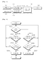
- Fig. 1 is a block diagram illustrating the configuration of an engine idling control device for an excavator according to the present invention.
- an engine idling control device for an excavator is configured to include a first signal detection unit 103, a second signal detection unit 104, and an engine idling control unit 105.
- the engine idling control device for an excavator includes a first signal detection unit 103 detecting an on/off state of a function selection switch 101; a second signal detection unit 104 detecting an operation state (on/off state) of a safety device 102; and an engine idling control unit 105 automatically stopping or driving an engine 106 in accordance with a state of the engine 106, the on/off state of the function selection switch 101 detected by the first signal detection unit 103, and the operation state of the safety device 102 detected by the second signal detection unit 104.
- the first signal detection unit 103 is electrically connected to the function selection switch 101 and the engine idling control unit 105, and detects and transfers the on/off state of the function selection switch 101, which is varied according to user's key operation, to the engine idling control unit 105.
- the second signal detection unit 104 is installed between the safety device 102 and the engine idling control unit 105, and detects and transfers the operation state (on/off state) of the safety device 102 (e.g., a control lock device installed inside an operator's seat of the excavator or a safety lever) to the engine idling control unit 105.
- the safety device 102 e.g., a control lock device installed inside an operator's seat of the excavator or a safety lever
- the engine idling control unit 105 is configured to automatically stop or drive the engine 106 in accordance with the state of the engine 106, the on/off state of the function selection switch 101 detected by the first signal detection unit 103, and the operation state of the safety device 102 detected by the second signal detection unit 104. Specifically, if the function selection switch 101 is turned off in a state where the engine is in a driving state, the engine stop and start function according to the present invention is not implemented, while if the function selection switch 101 is turned on, the engine stop and start function is implemented according to the user's operation state of the safety device 102. That is, if the function selection switch 101 is turned on and the user turns off the safety device 102, the engine 106 is automatically stopped. By contrast, if the safety device 102 is turned on in the case where the function selection switch 101 is turned on in a state where the engine 106 is stopped, the engine stop and start function is implemented to drive the engine 106.
- Fig. 2 is a flowchart illustrating in order the operation of an engine idling control device for an excavator according to the present invention.
- the first signal detection unit first detects the on/off state of the function selection switch (S201, S202, and S205).
- the first signal detection unit which is electrically connected to the function selection switch and the engine idling control unit, detects the on/off state of the function selection switch that is varied according to the user's key operation.
- the detected on/off state of the function selection switch is transferred to the engine idling control unit.
- the second signal detection unit detects the operation state (on/off state) of the safety device (S203 and S206).
- the second signal detection unit which is installed between the safety device and the engine idling control unit, detects the operation state (on/off state) of the safety device.
- the detected operation state of the safety device is transferred to the engine idling control unit.
- the safety device may be, for example, a control lock device installed inside an operator's seat of the excavator or a safety lever.
- the engine idling control unit automatically stops or drives the engine in accordance with the state of the engine, the on/off state of the function selection switch that is detected by the first signal detection unit, and the operation state of the safety device that is detected by the second signal detection unit (S204 and S207).
- the engine stop and start function according to the present invention is not implemented.
- the safety device is turned on in the case where the function selection switch is turned on in a state where the engine is stopped, i.e., if the user turns on the safety device, the engine stop and start function is implemented to start the engine driving.
- the state of the engine, the on/off state of the function selection switch, and the user's intention to work that has maximally been reflected can be recognized, and the fuel use and the production of carbon dioxide can be reduced through automatic stopping or driving of the engine in accordance with an operation state of a safety device having convenience. Further, the engine stop and start function can be implemented in accordance with the user's selection.
- Figs. 3A to 3C are graphs illustrating an engine stop state in controlling the stop and start of an engine according to the present invention as compared with the related art.
- Fig. 3A shows an engine stop operation in the related art, which lowers the engine revolution to the minimum revolution after a predetermined time elapses.
- Fig. 3B shows another engine stop operation in the related art, which turns off the engine after a predetermined time elapses in accordance with the time set through the existing engine idling control technology or the time set by the operator.
- the engine can be controlled to be stopped or driven at any time even if the time point where the operator commands stopping of the safety device differs.
- the present invention can be used in the engine idling control device for an excavator. More specifically, the present invention can be used in the engine idling control device for an excavator, which can recognize the state of the engine, the on/off state of the function selection switch, and the user's intention to work that has maximally been reflected, reduce the fuel use and the production of carbon dioxide through automatic stopping or driving of the engine in accordance with the operation state of the safety device having convenience, and easily implement the engine stop and start function in accordance with the user's selection.
Landscapes
- Engineering & Computer Science (AREA)
- General Engineering & Computer Science (AREA)
- Combustion & Propulsion (AREA)
- Chemical & Material Sciences (AREA)
- Mechanical Engineering (AREA)
- Civil Engineering (AREA)
- Structural Engineering (AREA)
- Mining & Mineral Resources (AREA)
- Transportation (AREA)
- Control Of Vehicle Engines Or Engines For Specific Uses (AREA)
- Output Control And Ontrol Of Special Type Engine (AREA)
- Operation Control Of Excavators (AREA)
- Electrical Control Of Air Or Fuel Supplied To Internal-Combustion Engine (AREA)
Abstract
Description
- The present invention relates to an engine idling control device for an excavator and a method thereof. More particularly, the present invention relates to an engine idling control device for an excavator and a method thereof, which can recognize the state of an engine, an on/off state of a function selection switch, and a user's intention to work that has maximally been reflected, reduce fuel use and production of carbon dioxide through automatic stopping or driving of the engine in accordance with an operation state of a safety device having convenience, and easily implement engine stop and start function in accordance with a user's selection.
- Generally, an excavator has a function of preventing unnecessary fuel consumption through lowering engine revolution to the minimum revolution (idle state) if an operation is not input for a predetermined time period in an engine driving state.
- Since the engine is continuously driven even in an idle state, fuel is consumed and carbon dioxide is produced. In order to solve this problem, Korean Patent Application No.
10-2001-0052517 - Therefore, the present invention has been made to solve the above-mentioned problems occurring in the related art, and one subject to be achieved by the present invention is to provide an engine idling control device for an excavator and a method thereof, which can recognize the state of an engine, an on/off state of a function selection switch, and a user's intention to work that has maximally been reflected, reduce fuel use and production of carbon dioxide through automatic stopping or driving of the engine in accordance with an operation state of a safety device having convenience, and easily implement engine stop and start function in accordance with a user's selection.
- In accordance with an aspect of the present invention, there is provided an engine idling control device for an excavator, which includes a first signal detection unit detecting an on/off state of a function selection switch; a second signal detection unit detecting an operation state (on/off state) of a safety device; and an engine idling control unit automatically stopping or driving an engine in accordance with a state of the engine, the on/off state of the function selection switch detected by the first signal detection unit, and the operation state of the safety device detected by the second signal detection unit.
- The engine idling control unit may automatically stop the engine if the function selection switch is turned on and the safety device is turned off in a state where the engine is driven, and may drive the engine if the function selection switch is turned on and the safety device is turned on in a state where the engine is stopped.
- The safety device may be any one of a control lock device that is installed inside an operator's seat of the excavator and a safety lever.
- In accordance with another aspect of the present invention, there is provided a method of controlling engine idling for an excavator, which includes detecting an on/off state of a function selection switch; detecting an operation state (on/off state) of a safety device; and automatically stopping or driving an engine in accordance with a state of the engine, the detected on/off state of the function selection switch, and the detected operation state of the safety device.
- The step of automatically stopping or driving the engine may automatically stop the engine if the function selection switch is turned on and the safety device is turned off in a state where the engine is driven, and may drive the engine if the function selection switch is turned on and the safety device is turned on in a state where the engine is stopped.
- The safety device may be any one of a control lock device that is installed inside an operator's seat of the excavator and a safety lever.
- According to the present invention, the state of the engine, the on/off state of the function selection switch, and the user's intention to work that has maximally been reflected can be recognized, and the fuel use and the production of carbon dioxide can be reduced through automatic stopping or driving of the engine in accordance with an operation state of a safety device having convenience. Further, the engine stop and start function can be implemented in accordance with the user's selection.
- The above objects, other features and advantages of the present invention will become more apparent by describing the preferred embodiments thereof with reference to the accompanying drawings, in which:
-
Fig. 1 is a block diagram illustrating the configuration of an engine idling control device for an excavator according to the present invention; -
Fig. 2 is a flowchart illustrating in order the operation of an engine idling control device for an excavator according to the present invention; and -
Figs. 3A to 3C are graphs illustrating an engine stop state in controlling the stop and start of an engine according to the present invention as compared with the related art. -
- 101: function selection switch
- 102: safety device
- 103: first signal detection unit
- 104: second signal detection unit
- 105: engine idling control unit
- 106: engine
- Now, a preferred embodiment of the present invention will be described in detail with reference to the accompanying drawings.
-
Fig. 1 is a block diagram illustrating the configuration of an engine idling control device for an excavator according to the present invention. - As illustrated in
Fig. 1 , an engine idling control device for an excavator according to the present invention is configured to include a firstsignal detection unit 103, a secondsignal detection unit 104, and an engineidling control unit 105. - That is, the engine idling control device for an excavator according to the present invention includes a first
signal detection unit 103 detecting an on/off state of afunction selection switch 101; a secondsignal detection unit 104 detecting an operation state (on/off state) of asafety device 102; and an engineidling control unit 105 automatically stopping or driving anengine 106 in accordance with a state of theengine 106, the on/off state of thefunction selection switch 101 detected by the firstsignal detection unit 103, and the operation state of thesafety device 102 detected by the secondsignal detection unit 104. - Here, the first
signal detection unit 103 is electrically connected to thefunction selection switch 101 and the engineidling control unit 105, and detects and transfers the on/off state of thefunction selection switch 101, which is varied according to user's key operation, to the engineidling control unit 105. - The second
signal detection unit 104 is installed between thesafety device 102 and the engineidling control unit 105, and detects and transfers the operation state (on/off state) of the safety device 102 (e.g., a control lock device installed inside an operator's seat of the excavator or a safety lever) to the engineidling control unit 105. - The engine
idling control unit 105 is configured to automatically stop or drive theengine 106 in accordance with the state of theengine 106, the on/off state of thefunction selection switch 101 detected by the firstsignal detection unit 103, and the operation state of thesafety device 102 detected by the secondsignal detection unit 104. Specifically, if thefunction selection switch 101 is turned off in a state where the engine is in a driving state, the engine stop and start function according to the present invention is not implemented, while if thefunction selection switch 101 is turned on, the engine stop and start function is implemented according to the user's operation state of thesafety device 102. That is, if thefunction selection switch 101 is turned on and the user turns off thesafety device 102, theengine 106 is automatically stopped. By contrast, if thesafety device 102 is turned on in the case where thefunction selection switch 101 is turned on in a state where theengine 106 is stopped, the engine stop and start function is implemented to drive theengine 106. - Hereinafter the operation of the engine idling control device for an excavator according to the present invention of
Fig. 1 will be described with reference toFig. 2 . -
Fig. 2 is a flowchart illustrating in order the operation of an engine idling control device for an excavator according to the present invention. - As illustrated in
Fig. 2 , the first signal detection unit first detects the on/off state of the function selection switch (S201, S202, and S205). - That is, the first signal detection unit, which is electrically connected to the function selection switch and the engine idling control unit, detects the on/off state of the function selection switch that is varied according to the user's key operation.
- Then, the detected on/off state of the function selection switch is transferred to the engine idling control unit.
- Next, the second signal detection unit detects the operation state (on/off state) of the safety device (S203 and S206).
- That is, the second signal detection unit, which is installed between the safety device and the engine idling control unit, detects the operation state (on/off state) of the safety device.
- Then, the detected operation state of the safety device is transferred to the engine idling control unit.
- The safety device may be, for example, a control lock device installed inside an operator's seat of the excavator or a safety lever.
- Next, the engine idling control unit automatically stops or drives the engine in accordance with the state of the engine, the on/off state of the function selection switch that is detected by the first signal detection unit, and the operation state of the safety device that is detected by the second signal detection unit (S204 and S207).
- Specifically, if the function selection switch is turned off in a state where the engine is driven, the engine stop and start function according to the present invention is not implemented.
- By contrast, if the function selection switch is turned on, the engine stop and start function is implemented in accordance with the user's operation of the safety device.
- That is, if the function selection switch is turned on and the user turns off the safety device, the engine is automatically stopped.
- By contrast, if the safety device is turned on in the case where the function selection switch is turned on in a state where the engine is stopped, i.e., if the user turns on the safety device, the engine stop and start function is implemented to start the engine driving.
- As described above, according to the present invention, the state of the engine, the on/off state of the function selection switch, and the user's intention to work that has maximally been reflected can be recognized, and the fuel use and the production of carbon dioxide can be reduced through automatic stopping or driving of the engine in accordance with an operation state of a safety device having convenience. Further, the engine stop and start function can be implemented in accordance with the user's selection.
-
Figs. 3A to 3C are graphs illustrating an engine stop state in controlling the stop and start of an engine according to the present invention as compared with the related art. -
Fig. 3A shows an engine stop operation in the related art, which lowers the engine revolution to the minimum revolution after a predetermined time elapses.Fig. 3B shows another engine stop operation in the related art, which turns off the engine after a predetermined time elapses in accordance with the time set through the existing engine idling control technology or the time set by the operator. Unlike the related art as described above, according to the present invention as illustrated inFig. 3C , the engine can be controlled to be stopped or driven at any time even if the time point where the operator commands stopping of the safety device differs. - As apparent from the above description, the present invention can be used in the engine idling control device for an excavator. More specifically, the present invention can be used in the engine idling control device for an excavator, which can recognize the state of the engine, the on/off state of the function selection switch, and the user's intention to work that has maximally been reflected, reduce the fuel use and the production of carbon dioxide through automatic stopping or driving of the engine in accordance with the operation state of the safety device having convenience, and easily implement the engine stop and start function in accordance with the user's selection.
Claims (6)
- An engine idling control device for an excavator, comprising:a first signal detection unit detecting an on/off state of a function selection switch;a second signal detection unit detecting an operation state (on/off state) of a safety device; andan engine idling control unit automatically stopping or driving an engine in accordance with a state of the engine, the on/off state of the function selection switch detected by the first signal detection unit, and the operation state of the safety device detected by the second signal detection unit.
- The engine idling control device according to claim 1, wherein the engine idling control unit automatically stops the engine if the function selection switch is turned on and the safety device is turned off in a state where the engine is driven, and drives the engine if the function selection switch is turned on and the safety device is turned on in a state where the engine is stopped.
- The engine idling control device according to claim 1, wherein the safety device is any one of a control lock device that is installed inside an operator's seat of the excavator and a safety device.
- A method of controlling engine idling for an excavator, comprising:detecting an on/off state of a function selection switch;detecting an operation state (on/off state) of a safety device; andautomatically stopping or driving an engine in accordance with a state of the engine, the detected on/off state of the function selection switch, and the detected operation state of the safety device.
- The method of controlling engine idling according to claim 4, wherein the step of automatically stopping or driving the engine automatically stops the engine if the function selection switch is turned on and the safety device is turned off in a state where the engine is driven, and drives the engine if the function selection switch is turned on and the safety device is turned on in a state where the engine is stopped.
- The method of controlling engine idling according to claim 4, wherein the safety device is any one of a control lock device that is installed inside an operator's seat of the excavator and a safety lever.
Applications Claiming Priority (1)
| Application Number | Priority Date | Filing Date | Title |
|---|---|---|---|
| PCT/KR2010/009000 WO2012081745A1 (en) | 2010-12-16 | 2010-12-16 | Engine idling control device of excavator and method thereof |
Publications (2)
| Publication Number | Publication Date |
|---|---|
| EP2653705A1 true EP2653705A1 (en) | 2013-10-23 |
| EP2653705A4 EP2653705A4 (en) | 2015-07-01 |
Family
ID=46244834
Family Applications (1)
| Application Number | Title | Priority Date | Filing Date |
|---|---|---|---|
| EP10860791.2A Withdrawn EP2653705A4 (en) | 2010-12-16 | 2010-12-16 | MOTOR IDLE CONTROL DEVICE OF EXCAVATOR AND ASSOCIATED METHOD |
Country Status (6)
| Country | Link |
|---|---|
| US (1) | US20130268166A1 (en) |
| EP (1) | EP2653705A4 (en) |
| JP (1) | JP2014501346A (en) |
| KR (1) | KR20130127467A (en) |
| CN (1) | CN103261638A (en) |
| WO (1) | WO2012081745A1 (en) |
Cited By (1)
| Publication number | Priority date | Publication date | Assignee | Title |
|---|---|---|---|---|
| EP3572665A1 (en) * | 2018-05-25 | 2019-11-27 | Wacker Neuson Linz GmbH | Automatic idle deactivation system for work vehicles |
Families Citing this family (3)
| Publication number | Priority date | Publication date | Assignee | Title |
|---|---|---|---|---|
| JP5705706B2 (en) * | 2011-11-15 | 2015-04-22 | 日立建機株式会社 | Engine control device for work vehicle |
| CN103362665A (en) * | 2013-08-01 | 2013-10-23 | 徐州重型机械有限公司 | Crane and method and system for controlling flameout of engine |
| EP3133275A4 (en) * | 2014-04-15 | 2018-04-25 | Volvo Construction Equipment AB | Engine control system using isg |
Family Cites Families (19)
| Publication number | Priority date | Publication date | Assignee | Title |
|---|---|---|---|---|
| JPS58162744A (en) * | 1982-03-23 | 1983-09-27 | Nissan Motor Co Ltd | Stopping and starting controller for automobile engine |
| US6048369A (en) | 1998-06-03 | 2000-04-11 | North Carolina State University | Method of dyeing hydrophobic textile fibers with colorant materials in supercritical fluid carbon dioxide |
| JP3797805B2 (en) * | 1998-09-22 | 2006-07-19 | 日立建機株式会社 | Engine control device for construction machinery |
| JP3825289B2 (en) * | 2001-08-27 | 2006-09-27 | 新キャタピラー三菱株式会社 | Engine control device for work machines |
| JP3737963B2 (en) * | 2001-11-16 | 2006-01-25 | 新キャタピラー三菱株式会社 | Construction machinery |
| JP4089270B2 (en) * | 2002-04-15 | 2008-05-28 | コベルコ建機株式会社 | Construction machine and engine control method thereof |
| JP3908639B2 (en) * | 2002-09-25 | 2007-04-25 | 株式会社クボタ | Engine control device for work equipment |
| JP2004339949A (en) * | 2003-05-13 | 2004-12-02 | Shin Caterpillar Mitsubishi Ltd | Method and device for controlling engine |
| GB2424964B (en) * | 2003-12-02 | 2007-05-16 | Komatsu Mfg Co Ltd | Construction machine |
| KR100621979B1 (en) * | 2004-03-22 | 2006-09-14 | 볼보 컨스트럭션 이키프먼트 홀딩 스웨덴 에이비 | Operating lever malfunction prevention system |
| JP2006022701A (en) * | 2004-07-07 | 2006-01-26 | Shin Caterpillar Mitsubishi Ltd | Engine control device in construction machine |
| JP4294563B2 (en) * | 2004-09-10 | 2009-07-15 | 日立建機株式会社 | Work machine |
| JP2006200370A (en) * | 2005-01-18 | 2006-08-03 | Mazda Motor Corp | Engine automatic stop / start control device |
| JP4632970B2 (en) * | 2005-03-04 | 2011-02-16 | 日立建機株式会社 | Work machine safety device and work machine service system |
| GB2427655B (en) * | 2005-06-29 | 2008-01-30 | Ford Global Tech Llc | A motor vehicle having a stop-start system |
| JP2008057469A (en) * | 2006-08-31 | 2008-03-13 | Shin Caterpillar Mitsubishi Ltd | Engine control device of work machine |
| KR100840424B1 (en) * | 2007-11-08 | 2008-06-20 | 손병덕 | Automobile engine starter and method |
| KR20100015065A (en) * | 2008-08-04 | 2010-02-12 | 김현수 | An idling stop device |
| KR100897040B1 (en) * | 2008-08-21 | 2009-05-14 | 유영환 | Vehicle idling force limiting device and method |
-
2010
- 2010-12-16 CN CN2010800707101A patent/CN103261638A/en active Pending
- 2010-12-16 JP JP2013544370A patent/JP2014501346A/en active Pending
- 2010-12-16 US US13/993,242 patent/US20130268166A1/en not_active Abandoned
- 2010-12-16 WO PCT/KR2010/009000 patent/WO2012081745A1/en not_active Ceased
- 2010-12-16 EP EP10860791.2A patent/EP2653705A4/en not_active Withdrawn
- 2010-12-16 KR KR1020137014937A patent/KR20130127467A/en not_active Ceased
Cited By (1)
| Publication number | Priority date | Publication date | Assignee | Title |
|---|---|---|---|---|
| EP3572665A1 (en) * | 2018-05-25 | 2019-11-27 | Wacker Neuson Linz GmbH | Automatic idle deactivation system for work vehicles |
Also Published As
| Publication number | Publication date |
|---|---|
| CN103261638A (en) | 2013-08-21 |
| EP2653705A4 (en) | 2015-07-01 |
| KR20130127467A (en) | 2013-11-22 |
| JP2014501346A (en) | 2014-01-20 |
| WO2012081745A1 (en) | 2012-06-21 |
| US20130268166A1 (en) | 2013-10-10 |
Similar Documents
| Publication | Publication Date | Title |
|---|---|---|
| US8435158B2 (en) | PTO control device | |
| JP6546426B2 (en) | Idle stop control device | |
| EP2542773B1 (en) | Vehicle control apparatus and method for controlling start and stop of an engine of a vehicle, especially when a hood of the engine is open | |
| CN103434397A (en) | Automobile accelerator control method, automobile accelerator control device and automobile | |
| EP1803914A4 (en) | Engine output control device and engine output control method for working machine | |
| CN104989537B (en) | Anti-flameout control method for hybrid power engine | |
| CN101939523A (en) | Method and apparatus for controlling a fuel metering system of an internal combustion engine | |
| JP2009013953A (en) | Engine automatic stop / start control device | |
| US20130268166A1 (en) | Engine idling control device of excavator and method thereof | |
| CN107850033A (en) | Actuator device for prime mover | |
| EP2375040A3 (en) | Engine control unit | |
| US7127940B2 (en) | Diagnosis method for liquefied petroleum injection fuel pump | |
| CN109306908A (en) | Remote throttle idle speed adjustment method, system and controller | |
| US6881172B2 (en) | Method and arrangement for automatically restarting a drive unit | |
| JP2007162676A (en) | Starter motor control device for automatic transmission vehicle | |
| US20220025839A1 (en) | Auto-stop start system for a vehicle | |
| KR20170013477A (en) | Control method for vehicle having power take off function | |
| JP5394971B2 (en) | Vehicle start control device | |
| CN103362665A (en) | Crane and method and system for controlling flameout of engine | |
| US10132284B2 (en) | Ignition device for an ISG-equipped vehicle using LGP as a fuel | |
| CN112780421B (en) | Method for continuously variable valve duration actuation control and system therefor | |
| US9556864B2 (en) | Method and device for controlling an auxiliary pump for a transmission | |
| KR20140050656A (en) | Method and device for monitoring a control unit for operating an engine system | |
| EP2169213A3 (en) | Starting system for fuel injection engine | |
| CN100426161C (en) | Parking shutdown method and module for portable automobile device |
Legal Events
| Date | Code | Title | Description |
|---|---|---|---|
| PUAI | Public reference made under article 153(3) epc to a published international application that has entered the european phase |
Free format text: ORIGINAL CODE: 0009012 |
|
| 17P | Request for examination filed |
Effective date: 20130611 |
|
| AK | Designated contracting states |
Kind code of ref document: A1 Designated state(s): AL AT BE BG CH CY CZ DE DK EE ES FI FR GB GR HR HU IE IS IT LI LT LU LV MC MK MT NL NO PL PT RO RS SE SI SK SM TR |
|
| DAX | Request for extension of the european patent (deleted) | ||
| RA4 | Supplementary search report drawn up and despatched (corrected) |
Effective date: 20150603 |
|
| RIC1 | Information provided on ipc code assigned before grant |
Ipc: F02N 11/08 20060101ALI20150528BHEP Ipc: F02D 17/04 20060101ALI20150528BHEP Ipc: B60W 30/18 20120101AFI20150528BHEP Ipc: E02F 9/20 20060101ALI20150528BHEP Ipc: F02N 11/10 20060101ALN20150528BHEP Ipc: F02D 29/02 20060101ALI20150528BHEP |
|
| STAA | Information on the status of an ep patent application or granted ep patent |
Free format text: STATUS: THE APPLICATION HAS BEEN WITHDRAWN |
|
| 18W | Application withdrawn |
Effective date: 20151202 |