EP2653690B1 - Two-stroke engine, in particular of Diesel type, with exhaust gas purging of the combustion chamber and a method for such a motor - Google Patents
Two-stroke engine, in particular of Diesel type, with exhaust gas purging of the combustion chamber and a method for such a motor Download PDFInfo
- Publication number
- EP2653690B1 EP2653690B1 EP13305323.1A EP13305323A EP2653690B1 EP 2653690 B1 EP2653690 B1 EP 2653690B1 EP 13305323 A EP13305323 A EP 13305323A EP 2653690 B1 EP2653690 B1 EP 2653690B1
- Authority
- EP
- European Patent Office
- Prior art keywords
- engine
- combustion chamber
- cylinder
- supercharged
- air
- Prior art date
- Legal status (The legal status is an assumption and is not a legal conclusion. Google has not performed a legal analysis and makes no representation as to the accuracy of the status listed.)
- Not-in-force
Links
Images
Classifications
-
- F—MECHANICAL ENGINEERING; LIGHTING; HEATING; WEAPONS; BLASTING
- F02—COMBUSTION ENGINES; HOT-GAS OR COMBUSTION-PRODUCT ENGINE PLANTS
- F02B—INTERNAL-COMBUSTION PISTON ENGINES; COMBUSTION ENGINES IN GENERAL
- F02B25/00—Engines characterised by using fresh charge for scavenging cylinders
- F02B25/02—Engines characterised by using fresh charge for scavenging cylinders using unidirectional scavenging
- F02B25/04—Engines having ports both in cylinder head and in cylinder wall near bottom of piston stroke
-
- F—MECHANICAL ENGINEERING; LIGHTING; HEATING; WEAPONS; BLASTING
- F02—COMBUSTION ENGINES; HOT-GAS OR COMBUSTION-PRODUCT ENGINE PLANTS
- F02B—INTERNAL-COMBUSTION PISTON ENGINES; COMBUSTION ENGINES IN GENERAL
- F02B31/00—Modifying induction systems for imparting a rotation to the charge in the cylinder
- F02B31/04—Modifying induction systems for imparting a rotation to the charge in the cylinder by means within the induction channel, e.g. deflectors
- F02B31/06—Movable means, e.g. butterfly valves
-
- Y—GENERAL TAGGING OF NEW TECHNOLOGICAL DEVELOPMENTS; GENERAL TAGGING OF CROSS-SECTIONAL TECHNOLOGIES SPANNING OVER SEVERAL SECTIONS OF THE IPC; TECHNICAL SUBJECTS COVERED BY FORMER USPC CROSS-REFERENCE ART COLLECTIONS [XRACs] AND DIGESTS
- Y02—TECHNOLOGIES OR APPLICATIONS FOR MITIGATION OR ADAPTATION AGAINST CLIMATE CHANGE
- Y02T—CLIMATE CHANGE MITIGATION TECHNOLOGIES RELATED TO TRANSPORTATION
- Y02T10/00—Road transport of goods or passengers
- Y02T10/10—Internal combustion engine [ICE] based vehicles
- Y02T10/12—Improving ICE efficiencies
Definitions
- the present invention relates to an internal combustion engine operating in a two-cycle cycle with scavenging of the residual burnt gases contained in its combustion chamber and to a scanning method for such an engine.
- It relates more particularly but not exclusively a two-stroke diesel type engine.
- a two-stroke engine comprises a cylinder comprising intake channels with intake ports that open into the combustion chamber of this engine and at least one exhaust means which makes it possible to evacuate the burned gases. resulting from the combustion of a fuel mixture.
- This chamber is delimited by the wall of the cylinder on which the lights arrive, the top of a piston which slides in this cylinder in a rectilinear reciprocating movement between a top dead center and a bottom dead center, and the part of the bolt that closes. the top of the cylinder.
- This cylinder head carries the exhaust means which comprises an exhaust manifold controlled by an exhaust valve.
- this cylinder head also carries a fuel injector for introducing this fuel into the combustion chamber.
- the power delivered by this engine is dependent on the amount of air introduced into its combustion chamber, amount of air which is itself proportional to the density of this air.
- the amount of air admitted into the combustion chamber through the lights is thus increased by compression of the air, as by a turbocharger or a driven compressor, prior to its admission into the combustion chamber.
- This step is more commonly called flue gas scavenging and is usually performed at the beginning of the intake phase of the engine by making a short circuit between the intake and the exhaust.
- the exhaust valve is controlled opening to evacuate the exhaust gas contained in the combustion chamber.
- the piston discovers the intake lights. Supercharged air is thus introduced into the combustion chamber by pushing the exhaust gases towards the exhaust valve which is open.
- the exhaust valve is closed and the compressed air intake continues until the piston obstructs the intake ports so that the compression phase this air can be realized.
- the combustion chamber is not completely filled with intake air, which can only disrupt the desired course of combustion while reducing the performance of this engine.
- the intake air scans the inner periphery of the cylinder to evacuate the flue gases present therein to the exhaust means.
- the intake air that enters the combustion chamber is deflected by a deflecting surface on the top of the piston to direct the intake airflow substantially in the center of the chamber. combustion to scavenge residual flue gases.
- This device has the major drawbacks of requiring different types of inclined direction channels, which can only complicate the realization of the cylinder and increase its cost while being inefficient at certain speeds or on certain operating points of the engine.
- the top of the piston has a deflecting surface which requires a specific embodiment to obtain the desired orientation.
- this deflecting surface disrupts in a significant way the unfolding of the combustion of the fuel mixture and can introduce significant heating points that could jeopardize the integrity of the piston.
- the present invention proposes to overcome the above drawbacks by means of an engine which makes it possible to scan the residual burned gases, at all speeds, in an efficient manner so as to obtain a high efficiency while being of a simple and slightly expensive.
- the present invention relates to a two-cycle internal combustion engine comprising at least one cylinder with a chamber of combustion, at least one exhaust means with an exhaust manifold controlled by an exhaust valve, air intake channels in which supercharged intake air circulates and discharges into said chamber through lights and comprising movable means of multidirectional orientation of the supercharged air flow to the combustion chamber, characterized in that the multidirectional orientation of the movable means comprises an angularly movable nozzle.
- the multi-directional moving means can be placed near the lights.
- the multidirectional orientation of the movable means may comprise a nozzle shaped flattened.
- the nozzle may include a bore for the circulation of the supercharged air to the combustion chamber.
- the bore may have a section similar to those of the lights.
- the invention also relates to a method for scavenging the residual burnt gases contained in the combustion chamber of a two-cycle internal combustion engine, said engine comprising at least one cylinder, at least one exhaust means with a tubing of exhaust controlled by an exhaust valve, air intake channels in which supercharged intake air circulates and opening into said chamber by lights, characterized in that it consists in guiding in directions multiple supercharged air flow circulating in the channels to introduce it into the combustion chamber.
- the method may include directing the supercharged airflow tangentially relative to the inner wall of the cylinder.
- the method may include directing the supercharged airflow axially relative to the longitudinal axis of the cylinder.
- the two-stroke internal combustion engine comprises at least one cylinder 10 of axis XX inside which slides a piston 12 in a reciprocating rectilinear motion.
- This cylinder comprises a combustion chamber 14 delimited by the inner wall 16 of the cylinder, the top 18 of the piston 12 and the part of the cylinder head 20 which closes the top of the cylinder.
- the cylinder head carries at least one exhaust gas exhaust means 22 from the combustion of a fuel mixture in the combustion chamber.
- This means comprises an exhaust pipe 24 arriving in the combustion chamber and controlled by an exhaust valve 26.
- an exhaust valve 26 In the example described, there are provided four escape means regularly distributed circumferentially.
- control means such as a camshaft, an electric type cylinder, electrohydraulic, ...
- a fuel injector (symbolized by the center line 28) is carried by this cylinder head to introduce fuel into the chamber of combustion.
- the cylinder head may also carry ignition means of the fuel mixture such as a spark plug (not shown) for the use of a two-stroke spark ignition engine.
- ignition means of the fuel mixture such as a spark plug (not shown) for the use of a two-stroke spark ignition engine.
- the cylinder 10 comprises at least one air intake means 30 for supplying supercharged air inside the combustion chamber to produce a fuel mixture.
- admission means are provided being distributed regularly circumferentially at 60 °.
- This intake means comprises a substantially horizontal air intake duct 32 which is provided in the wall 34 of the cylinder 10 and which opens out through a hole 36 in the combustion chamber of the engine and above the top 18 of the piston when this one is in the bottom dead center position.
- These channels are in quadrilateral section, here rectangular with the large sides of the rectangle substantially horizontal, but any other shape is conceivable as a circular shape.
- a compression means 38 such as a lobe-type driven compressor or a turbocharger, so as to introduce compressed air (or supercharged air) into these channels by an air distribution device. supercharged 40.
- the channels 32 are provided, in the vicinity of the slots 36, movable means 42 for directing the flow of air to the combustion chamber.
- these means comprise a nozzle 44 movable angularly in the form of flattened ball.
- This nozzle comprises a body 46 in which is formed a bore 48 opening on two flat faces vertical 50 substantially parallel to each other and octagonal to the bore.
- This bore is similar in shape to that of the channel 32 and therefore has a rectangular section.
- This bore is, in the position of rest of the nozzle, of general direction confused with that of the channel 32 (see right part of Figures 1 and 2 ).
- the body of the nozzle also carries two opposed convex spherical bearing surfaces, an upper 52 and a lower 54 facing the long sides of the bore and two other convex spherical bearing surfaces 56 and 58 vis-à-vis the short sides of the channel .
- spherical bearing surfaces bear directly on the sides of the channel, as illustrated in the figures, by providing an air-tightness device (not shown) between the spherical bearings and the sides of the channel, such as complementary concave spherical bearing surfaces. by these sides.
- the nozzle is fixedly mounted in the channel but is rotatable in all directions.
- the nozzle is connected to a control device (not shown) which makes it possible to pivot this nozzle around a rotation axis YY substantially orthogonal to that of the longitudinal axis XX of the cylinder (see left-hand part). of the figure 3 ) and / or about another axis of rotation ZZ which is substantially parallel to that of the cylinder (see left part of the figure 4 ).
- nozzles are controlled independently of each other, or so follow the same command.
- the piston 12 arrives at the position P1 indicated on the figure 3 by masking the lights 36 of the channels 32.
- the lights are gradually discovered by the piston and supercharged air is introduced into the combustion chamber 14 by passing through the bores 48 of the nozzles 44.
- the introduced air allows to repel the burned gases still present in the chamber combustion to the exhaust valves 26 to evacuate through the pipes 24.
- the computer will then control the nozzle control device 44 so that these nozzles can ensure the scavenging of residual burnt gases in the central portion of the combustion chamber 14 and / or in peripheral portion .
- the nozzle is rotated to form a non-zero angle ⁇ , clockwise or counterclockwise, with a vertical plane passing through the axis XX of the cylinder and the axis of rotation ZZ ( figure 4 ) to direct the supercharged airflow in the vicinity of the wall 16 of the cylinder by creating a substantially circumferential flow of this airflow (clockwise or counterclockwise). This thus ensures the scanning of the burned gas pocket trapped on the periphery of the combustion chamber 14.
- This swirl is necessary to improve the homogeneity of the air / fuel mixture, but it must also be limited. Indeed, too much swirl can, in some cases, hinder the good performance of the combustion, and can even increase generating a bad combustion of the fuel mixture with the production of smoke.
- This nozzle may also be rotated to form a non-zero angle ⁇ , counterclockwise, with a horizontal plane passing through the axis of rotation YY of the nozzle ( figure 3 ).
- This inclination thus makes it possible to direct the supercharged air flow exiting the nozzle towards the axis XX in the central part of the cylinder 10 with an almost axial circulation to push the burnt gases towards the exhaust valves.
- the inclination angles ⁇ and p can be maintained fixed throughout the piston stroke between the points P1 and PMB or be gradually variable between these two points.
- the nozzle may be inclined at an angle ⁇ for the peripheral scanning of the burned gases contained in the cylinder or at an angle ⁇ for scanning in the central portion of this cylinder or at both an angle ⁇ and ⁇ for peripheral and central scanning of residual flue gas.
- valves are controlled to close and the introduction into the combustion chamber of the supercharged air continues until at the bottom dead center of the piston to continue filling the combustion chamber with supercharged air.
- the piston has a reverse stroke to its top dead center by gradually covering the lights until completely hide at its position P1.
- the sweeping can be optimized depending on the operating point and a large majority of residual flue gas is removed from the combustion chamber to be replaced by supercharged air.
Description
La présente invention se rapporte à un moteur à combustion interne fonctionnant selon un cycle à deux temps avec balayage des gaz brûlés résiduels contenus dans sa chambre de combustion et à un procédé de balayage pour un tel moteur.The present invention relates to an internal combustion engine operating in a two-cycle cycle with scavenging of the residual burnt gases contained in its combustion chamber and to a scanning method for such an engine.
Elle concerne plus particulièrement mais non exclusivement un moteur deux temps de type Diesel.It relates more particularly but not exclusively a two-stroke diesel type engine.
Comme cela est connu, un moteur deux temps comprend un cylindre comportant des canaux d'admission avec des lumières d'admission qui débouchent dans la chambre de combustion de ce moteur et au moins un moyen d'échappement qui permet d'évacuer les gaz brûlés résultant de la combustion d'un mélange carburé. Cette chambre est délimitée par la paroi du cylindre sur laquelle arrivent les lumières, le haut d'un piston qui coulisse dans ce cylindre en un mouvement rectiligne alternatif entre un point mort haut et un point mort bas, et la partie de la culasse qui ferme le haut du cylindre.As is known, a two-stroke engine comprises a cylinder comprising intake channels with intake ports that open into the combustion chamber of this engine and at least one exhaust means which makes it possible to evacuate the burned gases. resulting from the combustion of a fuel mixture. This chamber is delimited by the wall of the cylinder on which the lights arrive, the top of a piston which slides in this cylinder in a rectilinear reciprocating movement between a top dead center and a bottom dead center, and the part of the bolt that closes. the top of the cylinder.
Cette culasse porte le moyen d'échappement qui comprend une tubulure d'échappement contrôlée par une soupape d'échappement.This cylinder head carries the exhaust means which comprises an exhaust manifold controlled by an exhaust valve.
Dans le cas d'un moteur avec injection directe de carburant, comme un moteur Diesel, cette culasse porte également un injecteur de carburant permettant d'introduire ce carburant dans la chambre de combustion.In the case of an engine with direct fuel injection, such as a diesel engine, this cylinder head also carries a fuel injector for introducing this fuel into the combustion chamber.
Généralement, la puissance délivrée par ce moteur est dépendante de la quantité d'air introduite dans sa chambre de combustion, quantité d'air qui est elle-même proportionnelle à la densité de cet air.Generally, the power delivered by this engine is dependent on the amount of air introduced into its combustion chamber, amount of air which is itself proportional to the density of this air.
La quantité d'air admise dans la chambre de combustion au travers des lumières est donc augmentée par compression de l'air, comme par un turbocompresseur ou un compresseur entraîné, au préalable de son admission dans cette chambre de combustion.The amount of air admitted into the combustion chamber through the lights is thus increased by compression of the air, as by a turbocharger or a driven compressor, prior to its admission into the combustion chamber.
De manière à pouvoir encore plus augmenter cette quantité d'air dans la chambre de combustion du cylindre, il est prévu d'évacuer les gaz brûlés résiduels contenus initialement dans la chambre de combustion pour les remplacer par de l'air comprimé (ou air suralimenté).In order to further increase this amount of air in the combustion chamber of the cylinder, it is expected to evacuate the burnt gases residuals initially contained in the combustion chamber to replace them with compressed air (or supercharged air).
Cette étape est plus communément appelée balayage des gaz brûlés et se réalise généralement au début de la phase d'admission du moteur en réalisant un court-circuitage entre l'admission et l'échappement.This step is more commonly called flue gas scavenging and is usually performed at the beginning of the intake phase of the engine by making a short circuit between the intake and the exhaust.
Plus précisément, au voisinage de la fin de la phase de combustion/détente du moteur, c'est-à-dire lorsque le piston est au voisinage du point mort bas et qu'il recouvre les lumières, la soupape d'échappement est commandée en ouverture pour évacuer les gaz d'échappement contenus dans la chambre de combustion.More specifically, near the end of the combustion / expansion phase of the engine, that is to say when the piston is in the vicinity of the bottom dead center and covers the lights, the exhaust valve is controlled opening to evacuate the exhaust gas contained in the combustion chamber.
En continuant sa course vers le point mort bas, le piston découvre les lumières d'admission. De l'air suralimenté est donc introduit dans la chambre de combustion en repoussant les gaz d'échappement vers la soupape d'échappement qui est ouverte.Continuing to the bottom dead center, the piston discovers the intake lights. Supercharged air is thus introduced into the combustion chamber by pushing the exhaust gases towards the exhaust valve which is open.
Après que le piston ait atteint le point mort bas, la soupape d'échappement est fermée et l'admission de l'air comprimé se poursuit jusqu'à ce que le piston obstrue les lumières d'admission de manière à ce que la phase compression de cet air puisse se réaliser.After the piston has reached the bottom dead center, the exhaust valve is closed and the compressed air intake continues until the piston obstructs the intake ports so that the compression phase this air can be realized.
Bien que donnant satisfaction, ce dispositif présente néanmoins des inconvénients non négligeables.Although satisfactory, this device nevertheless has significant disadvantages.
En effet, comme cela est mieux visible sur les
Par cela, la chambre de combustion n'est pas complètement remplie d'air d'admission, ce qui ne peut que perturber le déroulement souhaité de la combustion tout en diminuant les performances de ce moteur.By this, the combustion chamber is not completely filled with intake air, which can only disrupt the desired course of combustion while reducing the performance of this engine.
Pour obtenir un balayage optimum, il est connu par le brevet
Par l'intermédiaire de l'un de ces types de canaux, l'air d'admission balaye la périphérie interne du cylindre pour évacuer les gaz brûlés qui y sont présents vers le moyen d'échappement. Par l'autre de ces types, l'air d'admission qui pénètre dans la chambre de combustion est dévié par une surface déflectrice présente sur le haut du piston pour diriger le flux d'air d'admission sensiblement au centre de la chambre de combustion pour y balayer les gaz brûlés résiduels.Via one of these types of channels, the intake air scans the inner periphery of the cylinder to evacuate the flue gases present therein to the exhaust means. By the other of these types, the intake air that enters the combustion chamber is deflected by a deflecting surface on the top of the piston to direct the intake airflow substantially in the center of the chamber. combustion to scavenge residual flue gases.
Ce dispositif a pour inconvénients majeurs de nécessiter différents types de canaux de directions inclinées, ce qui ne peut que compliquer la réalisation du cylindre et augmenter son coût tout en étant inefficace à certains régimes ou sur certains points de fonctionnement du moteur.This device has the major drawbacks of requiring different types of inclined direction channels, which can only complicate the realization of the cylinder and increase its cost while being inefficient at certain speeds or on certain operating points of the engine.
De plus, le haut du piston comporte une surface déflectrice qui demande une réalisation spécifique pour obtenir l'orientation souhaitée.In addition, the top of the piston has a deflecting surface which requires a specific embodiment to obtain the desired orientation.
En outre, cette surface déflectrice perturbe d'une façon non négligeable le déroulement de la combustion du mélange carburé et peut introduire des points de chauffe importants pouvant mettre en péril l'intégrité du piston.In addition, this deflecting surface disrupts in a significant way the unfolding of the combustion of the fuel mixture and can introduce significant heating points that could jeopardize the integrity of the piston.
La présente invention se propose de remédier aux inconvénients ci-dessus grâce à un moteur qui permet de balayer les gaz brûlés résiduels, à tous les régimes, de manière efficace de façon à obtenir un rendement élevé tout en étant d'une conception simple et peu coûteuse.The present invention proposes to overcome the above drawbacks by means of an engine which makes it possible to scan the residual burned gases, at all speeds, in an efficient manner so as to obtain a high efficiency while being of a simple and slightly expensive.
A cet effet, la présente invention concerne un moteur à combustion interne de type deux temps comportant au moins un cylindre avec une chambre de combustion, au moins un moyen d'échappement avec une tubulure d'échappement contrôlée par une soupape d'échappement, des canaux d'admission d'air dans lesquels circule de l'air suralimenté d'admission et débouchant dans ladite chambre par des lumières et comportant des moyens mobiles d'orientation multidirectionnelle du flux d'air suralimenté vers la chambre de combustion, caractérisé en ce que les moyens mobiles d'orientation multidirectionnelle comporte une buse mobile angulairement.For this purpose, the present invention relates to a two-cycle internal combustion engine comprising at least one cylinder with a chamber of combustion, at least one exhaust means with an exhaust manifold controlled by an exhaust valve, air intake channels in which supercharged intake air circulates and discharges into said chamber through lights and comprising movable means of multidirectional orientation of the supercharged air flow to the combustion chamber, characterized in that the multidirectional orientation of the movable means comprises an angularly movable nozzle.
Les moyens mobiles d'orientation multidirectionnelle peuvent être placés à proximité des lumières.The multi-directional moving means can be placed near the lights.
Les moyens mobiles d'orientation multidirectionnelle peuvent comporter une buse en forme de rotule aplatie.The multidirectional orientation of the movable means may comprise a nozzle shaped flattened.
La buse peut comporter un alésage pour la circulation de l'air suralimenté vers la chambre de combustion.The nozzle may include a bore for the circulation of the supercharged air to the combustion chamber.
L'alésage peut comporter une section semblable à celles des lumières.The bore may have a section similar to those of the lights.
L'invention concerne également un procédé de balayage des gaz brûlés résiduels contenus dans la chambre de combustion d'un moteur à combustion interne de type deux temps, ledit moteur comportant au moins un cylindre, au moins un moyen d'échappement avec une tubulure d'échappement contrôlée par une soupape d'échappement, des canaux d'admission d'air dans lesquels circule de l'air suralimenté d'admission et débouchant dans ladite chambre par des lumières, caractérisé en ce qu'il consiste à guider dans des directions multiples le flux d'air suralimenté circulant dans les canaux pour l'introduire dans la chambre de combustion.The invention also relates to a method for scavenging the residual burnt gases contained in the combustion chamber of a two-cycle internal combustion engine, said engine comprising at least one cylinder, at least one exhaust means with a tubing of exhaust controlled by an exhaust valve, air intake channels in which supercharged intake air circulates and opening into said chamber by lights, characterized in that it consists in guiding in directions multiple supercharged air flow circulating in the channels to introduce it into the combustion chamber.
Le procédé peut consister à diriger le flux d'air suralimenté tangentiellement par rapport à la paroi interne du cylindre.The method may include directing the supercharged airflow tangentially relative to the inner wall of the cylinder.
Le procédé peut consister à diriger le flux d'air suralimenté axialement par rapport à l'axe longitudinal du cylindre.The method may include directing the supercharged airflow axially relative to the longitudinal axis of the cylinder.
Les autres caractéristiques et avantages de l'invention vont apparaître maintenant à la lecture de la description qui va suivre, donnée à titre uniquement illustratif et non limitatif, et à laquelle sont annexées :
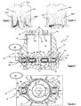
- la
figure 3 qui montre un moteur deux temps en coupe axiale partielle avec balayage de gaz brûlés selon l'invention; et - la
figure 4 qui montre ce moteur en coupe radiale partielle.
- the
figure 3 which shows a two-stroke engine in partial axial section with fluegas scavenging according to the invention; and - the
figure 4 which shows this engine in partial radial section.
Sur les
Ce cylindre comporte une chambre de combustion 14 délimitée par la paroi interne 16 du cylindre, le haut 18 du piston 12 et la partie de la culasse 20 qui ferme le haut du cylindre.This cylinder comprises a
La culasse porte au moins un moyen d'échappement de gaz brûlés 22 provenant de la combustion d'un mélange carburé dans la chambre de combustion. Ce moyen comporte une tubulure d'échappement 24 arrivant dans la chambre de combustion et contrôlée par une soupape d'échappement 26. Dans l'exemple décrit, il est prévu quatre moyens d'échappement régulièrement répartis circonférentiellement.The cylinder head carries at least one exhaust gas exhaust means 22 from the combustion of a fuel mixture in the combustion chamber. This means comprises an
Comme cela est généralement connu, les soupapes d'échappement suivent une course d'ouverture/fermeture de la tubulure sous l'impulsion de moyens de commande, comme un arbre à came, un vérin de type électrique, électrohydraulique, ...As is generally known, the exhaust valves follow a stroke of opening / closing of the tubing under the influence of control means, such as a camshaft, an electric type cylinder, electrohydraulic, ...
Dans le cas d'un moteur deux temps avec injection directe de carburant, tel qu'un moteur de type Diesel, un injecteur de carburant (symbolisé par le trait d'axe 28) est porté par cette culasse pour introduire du carburant dans la chambre de combustion.In the case of a two-stroke engine with direct fuel injection, such as a diesel type engine, a fuel injector (symbolized by the center line 28) is carried by this cylinder head to introduce fuel into the chamber of combustion.
Bien entendu et cela sans sortir du cadre de l'invention, la culasse peut également porter un moyen d'allumage du mélange carburé comme une bougie à étincelle (non représentée) pour l'utilisation d'un moteur deux temps à allumage commandé.Of course, and without departing from the scope of the invention, the cylinder head may also carry ignition means of the fuel mixture such as a spark plug (not shown) for the use of a two-stroke spark ignition engine.
Le cylindre 10 comporte au moins un moyen d'admission d'air 30 pour amener de l'air suralimenté à l'intérieur de la chambre de combustion pour y réaliser un mélange carburé.The
Dans l'exemple illustré sur les figures, six moyens d'admission sont prévus en étant répartis régulièrement circonférentiellement à 60°.In the example illustrated in the figures, six admission means are provided being distributed regularly circumferentially at 60 °.
Ce moyen d'admission comprend un canal d'admission d'air 32 sensiblement horizontal qui est prévu dans la paroi 34 du cylindre 10 et qui débouche par une lumière 36 dans la chambre de combustion du moteur et au dessus du haut 18 du piston lorsque celui-ci est en position de point mort bas. Ces canaux sont en section de forme quadrilatérale, ici rectangulaire avec les grands côtés du rectangle sensiblement horizontaux, mais toute autre forme est envisageable comme une forme circulaire.This intake means comprises a substantially horizontal
Ces canaux sont alimentés en air par un moyen de compression 38, comme un compresseur entraîné de type à lobes ou un turbocompresseur, de façon à introduire de l'air comprimé (ou air suralimenté) dans ces canaux par un dispositif de distribution d'air suralimenté 40.These channels are supplied with air by a compression means 38, such as a lobe-type driven compressor or a turbocharger, so as to introduce compressed air (or supercharged air) into these channels by an air distribution device. supercharged 40.
Comme mieux visible sur les figures, les canaux 32 sont munis, au voisinage des lumières 36, de moyens mobiles d'orientation 42 du flux d'air vers la chambre de combustion.As best seen in the figures, the
Plus précisément, ces moyens comportent une buse 44 mobile angulairement sous forme de rotule aplatie. Cette buse comporte un corps 46 dans lequel est réalisé un alésage 48 débouchant sur deux faces planes verticales 50 sensiblement parallèles l'une à l'autre et octogonales à l'alésage. Cet alésage est de forme semblable à celle du canal 32 et présente donc une section rectangulaire. Cet alésage est, en position de repos de la buse, de direction générale confondue avec celui du canal 32 (voir partie droite des
Ces portées sphériques prennent appui directement sur les côtés du canal, comme illustré sur les figures, en prévoyant un dispositif d'étanchéité à l'air (non représenté) entre les portées sphériques et les côtés du canal, comme des portées sphériques concaves complémentaires portées par ces cotés.These spherical bearing surfaces bear directly on the sides of the channel, as illustrated in the figures, by providing an air-tightness device (not shown) between the spherical bearings and the sides of the channel, such as complementary concave spherical bearing surfaces. by these sides.
Ainsi, la buse est montée fixement dans le canal mais est mobile en rotation dans toutes les directions.Thus, the nozzle is fixedly mounted in the channel but is rotatable in all directions.
Pour assurer cette mobilité multidirectionnelle la buse est reliée à un dispositif de commande (non représenté) qui permet de faire pivoter cette buse autour d'un axe de rotation YY sensiblement orthogonal à celui de l'axe longitudinal XX du cylindre (voir la partie gauche de la
Bien entendu, il est à la portée de l'homme du métier d'envisager tous les dispositifs de commande qui permettent de réaliser cette mobilité, comme des micromoteurs électriques avec leurs rotors reliés aux axes de rotation de la buse, et dont la mise en action et le contrôle seront assurés par le calculateur que comporte ce moteur.Of course, it is within the abilities of those skilled in the art to consider all the control devices that make it possible to achieve this mobility, such as electric micromotors with their rotors connected to the axes of rotation of the nozzle, and whose implementation action and control will be provided by the calculator that includes this engine.
De même, il peut être envisagé que les buses soient commandées indépendamment les unes des autres, ou alors suivre la même commande.Similarly, it can be envisaged that the nozzles are controlled independently of each other, or so follow the same command.
Ainsi, en fonctionnement pendant la phase de combustion/détente du moteur, le piston 12 arrive à la position P1 indiqué sur la
A cette position, les soupapes d'échappement 26 s'ouvrent de manière à laisser s'échapper les gaz brûlés contenus dans la chambre 14 par les tubulures d'échappement 24 et le piston 12 continue sa course vers le point mort bas PMB.At this position, the
Pendant cette course, les lumières sont progressivement découvertes par le piston et de l'air suralimenté est introduit dans la chambre de combustion 14 en traversant les alésages 48 des buses 44. L'air introduit permet de repousser les gaz brûlés encore présents dans la chambre de combustion vers les soupapes d'échappement 26 pour les évacuer par les tubulures 24.During this race, the lights are gradually discovered by the piston and supercharged air is introduced into the
En fonction des conditions de fonctionnement du moteur, le calculateur commandera alors le dispositif de commande des buses 44 de façon à ce que ces buses puissent assurer le balayage des gaz brûlés résiduels en partie centrale de la chambre de combustion 14 et/ou en partie périphérique.Depending on the operating conditions of the engine, the computer will then control the
Plus précisément, la buse est commandée en rotation pour former un angle non nul a, dans le sens horaire ou antihoraire, avec un plan vertical passant par l'axe XX du cylindre et l'axe de rotation ZZ (
Le fait de créer un angle α plus ou moins important avec ces buses va permettre d'orienter le flux d'air correctement dans le cylindre en fonction du point de fonctionnement, mais il va aussi permettre d'ajuster le niveau du tourbillon circulaire autour de l'axe XX, ou swirl, dans le moteur. Ce niveau de swirl représente l'intensité avec laquelle l'air aura un mouvement circulaire dans le cylindre.The fact of creating a greater or lesser angle α with these nozzles will make it possible to orient the flow of air correctly in the cylinder according to the operating point, but it will also make it possible to adjust the level of the circular vortex around the XX axis, or swirl, in the engine. This level of swirl represents the intensity with which the air will have a circular motion in the cylinder.
Ce swirl est nécessaire pour améliorer l'homogénéité du mélange air/carburant, mais il doit être aussi limité. En effet, trop de swirl peut, dans certains cas, nuire au bon rendement de la combustion, et peut même augmenter générer une mauvaise combustion du mélange carburé avec la production de fumée.This swirl is necessary to improve the homogeneity of the air / fuel mixture, but it must also be limited. Indeed, too much swirl can, in some cases, hinder the good performance of the combustion, and can even increase generating a bad combustion of the fuel mixture with the production of smoke.
Cette buse peut aussi être commandée en rotation pour former un angle non nul β, dans le sens antihoraire, avec un plan horizontal passant par l'axe de rotation YY de la buse (
Bien étendu et cela sans sortir du cadre de l'invention, les angles d'inclinaison α et p peuvent être maintenus fixes tout au long de la course du piston entre les points P1 et PMB ou être progressivement variables entre ces deux points.Although extended and this without departing from the scope of the invention, the inclination angles α and p can be maintained fixed throughout the piston stroke between the points P1 and PMB or be gradually variable between these two points.
Ainsi, la buse peut être inclinée d'un angle α pour le balayage périphérique des gaz brûlés contenus dans le cylindre ou d'un angle β pour le balayage en partie centrale de ce cylindre ou à la fois d'un angle α et β pour le balayage périphérique et central des gaz brûlés résiduels.Thus, the nozzle may be inclined at an angle α for the peripheral scanning of the burned gases contained in the cylinder or at an angle β for scanning in the central portion of this cylinder or at both an angle α and β for peripheral and central scanning of residual flue gas.
Dès que l'étape de balayage est terminée, généralement à quelques degrés d'angle de vilebrequin avant le point mort bas du piston, les soupapes sont commandées en fermeture et l'introduction dans la chambre de combustion de l'air suralimenté se poursuit jusqu'au point mort bas du piston pour poursuivre le remplissage en air suralimenté de la chambre de combustion.As soon as the sweeping step is completed, generally at a few degrees of crankshaft angle before the bottom dead center of the piston, the valves are controlled to close and the introduction into the combustion chamber of the supercharged air continues until at the bottom dead center of the piston to continue filling the combustion chamber with supercharged air.
A partir de ce point, le piston a une course inverse vers son point mort haut en recouvrant progressivement les lumières jusqu'à les masquer complètement à sa position P1.From this point, the piston has a reverse stroke to its top dead center by gradually covering the lights until completely hide at its position P1.
Ainsi, grâce aux buses, le balayage peut être optimisé en fonction du point de fonctionnement et une grande majorité de gaz brûlés résiduels est évacuée de la chambre de combustion pour être remplacés par de l'air suralimenté.Thus, thanks to the nozzles, the sweeping can be optimized depending on the operating point and a large majority of residual flue gas is removed from the combustion chamber to be replaced by supercharged air.
De ce fait, la quantité d'air contenu dans la chambre de combustion est augmentée et les performances du moteur sont alors améliorées.As a result, the amount of air contained in the combustion chamber is increased and the performance of the engine is then improved.
Claims (8)
- A two-stroke type internal-combustion engine comprising at least one cylinder (10) with a combustion chamber (14), at least one exhaust means (22) with an exhaust manifold (24) controlled by an exhaust valve (26), air intake channels (32) wherein supercharged intake air circulates and which open into said chamber through ports (36), comprising mobile means (42) for multi-directional orientation of the supercharged air stream into combustion chamber (14), characterized in that the mobile multi-directional orientation means comprise an angularly mobile nozzle (44).
- An engine as claimed in claim 1, characterized in that the mobile multi-directional orientation means are arranged close to ports (36).
- An engine as claimed in any one of the previous claims, characterized in that the mobile multi-directional orientation means comprise a nozzle (44) in form of a flat eyeball.
- An engine as claimed in any one of the previous claims, characterized in that nozzle (44) comprises a bore (48) for circulation of the supercharged air to the combustion chamber.
- An engine as claimed in any one of the previous claims, characterized in that bore (48) comprises a section similar to the section of ports (36).
- A method of scavenging residual burnt gas contained in combustion chamber (14) of a two-stroke type internal-combustion engine, said engine comprising at least one cylinder (10), at least one exhaust means (22) with an exhaust manifold (24) controlled by an exhaust valve (26), air intake channels (32) wherein supercharged intake air circulates and which open into said chamber through ports (36), characterized in that it consists in guiding in multiple directions the supercharged air stream circulating in the channels so as to drive it into the combustion chamber.
- A burnt gas scavenging method as claimed in claim 6, characterized in that it consists in driving the supercharged air stream tangentially with respect to inner wall (16) of the cylinder.
- A burnt gas scavenging method as claimed in any one of claims 6 or 7, characterized in that it consists in driving the supercharged air stream axially with respect to longitudinal axis (XX) of the cylinder.
Applications Claiming Priority (1)
| Application Number | Priority Date | Filing Date | Title |
|---|---|---|---|
| FR1201158A FR2989732B1 (en) | 2012-04-19 | 2012-04-19 | TWO-STROKE ENGINE, ESPECIALLY OF DIESEL TYPE, WITH SCAN OF BURNER GASES FROM THE COMBUSTION CHAMBER AND SCANNING METHOD FOR SUCH AN ENGINE |
Publications (2)
| Publication Number | Publication Date |
|---|---|
| EP2653690A1 EP2653690A1 (en) | 2013-10-23 |
| EP2653690B1 true EP2653690B1 (en) | 2015-03-18 |
Family
ID=47997311
Family Applications (1)
| Application Number | Title | Priority Date | Filing Date |
|---|---|---|---|
| EP13305323.1A Not-in-force EP2653690B1 (en) | 2012-04-19 | 2013-03-19 | Two-stroke engine, in particular of Diesel type, with exhaust gas purging of the combustion chamber and a method for such a motor |
Country Status (2)
| Country | Link |
|---|---|
| EP (1) | EP2653690B1 (en) |
| FR (1) | FR2989732B1 (en) |
Families Citing this family (1)
| Publication number | Priority date | Publication date | Assignee | Title |
|---|---|---|---|---|
| CN110594008A (en) * | 2019-10-29 | 2019-12-20 | 中船动力研究院有限公司 | Scavenging device |
Family Cites Families (4)
| Publication number | Priority date | Publication date | Assignee | Title |
|---|---|---|---|---|
| GB437584A (en) | ||||
| AU525683B2 (en) * | 1976-12-21 | 1982-11-25 | Malz Nominees Pty. Ltd. | Internal combustion engine |
| DE19755689A1 (en) * | 1997-12-16 | 1999-06-24 | Blodig Guenter Priv Doz Dr Ing | Swirl adjusting device for IC engines |
| DE102010038192A1 (en) * | 2010-10-14 | 2012-04-19 | Dr. Ing. H.C. F. Porsche Aktiengesellschaft | Two-stroke engine for use in motor car, has intake channels arranged two-point symmetrical to cylinder axis and comprising positioning device that is continuously adjustable at respective flow cross-section |
-
2012
- 2012-04-19 FR FR1201158A patent/FR2989732B1/en not_active Expired - Fee Related
-
2013
- 2013-03-19 EP EP13305323.1A patent/EP2653690B1/en not_active Not-in-force
Also Published As
| Publication number | Publication date |
|---|---|
| FR2989732A1 (en) | 2013-10-25 |
| EP2653690A1 (en) | 2013-10-23 |
| FR2989732B1 (en) | 2016-05-27 |
Similar Documents
| Publication | Publication Date | Title |
|---|---|---|
| EP1700016B1 (en) | Method of controlling a supercharged engine, particularly an indirect injection engine | |
| EP3956551A1 (en) | Gas intake device comprising an oriented masking element | |
| EP2653690B1 (en) | Two-stroke engine, in particular of Diesel type, with exhaust gas purging of the combustion chamber and a method for such a motor | |
| EP1544434B1 (en) | Method for controlling turbo-charged internal-combustion engine | |
| EP3462006B1 (en) | Two-valve internal combustion engine | |
| FR2920853A1 (en) | Valve i.e. three-way control valve, for e.g. heat engine of motor vehicle, has rotating unit moved inside body for controlling passage of air through openings of body with defined law based on angular position of rotating unit in body | |
| FR3064676A1 (en) | COMPRESSION AIR INJECTION INTERNAL COMBUSTION ENGINE | |
| EP3788243A1 (en) | Gas inlet device with intersection of the inlet duct and the valve calibration inclined with respect to the fire face | |
| FR3071880B1 (en) | INTERNAL COMBUSTION ENGINE WITH DIRECT FUEL INJECTION WITHIN THE DIRECTION OF ADMISSION GAS MOVEMENT | |
| EP3462005B1 (en) | Elliptical combustion chamber | |
| EP0507648B1 (en) | Two-cycle engine with selective control for the charge introduced into the combustion chamber | |
| FR2770256A1 (en) | IC engine with direct injection and controlled ignition | |
| WO2009095573A1 (en) | Thermal engine for automobile, with high-yield chambers | |
| EP2674601A1 (en) | Method of scanning residual burnt gases by double valve lift for a two-stroke engine, in particular Diesel type. | |
| FR2803626A1 (en) | INTERNAL COMBUSTION ENGINE WITH DIRECT INJECTION WITH CONTROLLED VALVES | |
| EP0296899A1 (en) | Arrangement of a fuel feed system in a combustion chamber of a two-stroke engine in relation to the exhaust port | |
| FR2581422A1 (en) | TWO-STROKE ENGINE WITH CONTROLLED VALVES | |
| FR2910540A1 (en) | Internal combustion engine for motor vehicle, has derivation unit connecting passage to intake pipe, exhaust pipe and both intake and exhaust pipes when unit is in intake, exhaust and intermediate positions, respectively | |
| EP1870568B1 (en) | Internal combustion engine with indirect injection, in particular a supercharged engine with controlled ignition with two intakes to provide a phase of scavenging burned gases | |
| FR2989731A1 (en) | Two-stroke type internal combustion engine i.e. two-stroke type diesel engine, has air intake channels opened in chamber via openings, and variable closing unit provided with engine for closing channels | |
| FR2676503A1 (en) | Heat (combustion) engine | |
| FR2731045A1 (en) | IC. engine feed control system | |
| FR2531139A1 (en) | Control device for a gas circuit of a combustion chamber | |
| FR2836180A1 (en) | Inlet valve orifice seating for camless internal combustion engine, comprises rim which has variable length along the valve axis and produces tumbling and better combustion on partial valve opening | |
| FR2763996A1 (en) | INTERNAL COMBUSTION ENGINE WITH CONTROLLED IGNITION COMPRISING THREE VALVES PER CYLINDER |
Legal Events
| Date | Code | Title | Description |
|---|---|---|---|
| PUAI | Public reference made under article 153(3) epc to a published international application that has entered the european phase |
Free format text: ORIGINAL CODE: 0009012 |
|
| AK | Designated contracting states |
Kind code of ref document: A1 Designated state(s): AL AT BE BG CH CY CZ DE DK EE ES FI FR GB GR HR HU IE IS IT LI LT LU LV MC MK MT NL NO PL PT RO RS SE SI SK SM TR |
|
| AX | Request for extension of the european patent |
Extension state: BA ME |
|
| 17P | Request for examination filed |
Effective date: 20140423 |
|
| RBV | Designated contracting states (corrected) |
Designated state(s): AL AT BE BG CH CY CZ DE DK EE ES FI FR GB GR HR HU IE IS IT LI LT LU LV MC MK MT NL NO PL PT RO RS SE SI SK SM TR |
|
| GRAP | Despatch of communication of intention to grant a patent |
Free format text: ORIGINAL CODE: EPIDOSNIGR1 |
|
| INTG | Intention to grant announced |
Effective date: 20150105 |
|
| GRAS | Grant fee paid |
Free format text: ORIGINAL CODE: EPIDOSNIGR3 |
|
| GRAA | (expected) grant |
Free format text: ORIGINAL CODE: 0009210 |
|
| AK | Designated contracting states |
Kind code of ref document: B1 Designated state(s): AL AT BE BG CH CY CZ DE DK EE ES FI FR GB GR HR HU IE IS IT LI LT LU LV MC MK MT NL NO PL PT RO RS SE SI SK SM TR |
|
| REG | Reference to a national code |
Ref country code: GB Ref legal event code: FG4D Free format text: NOT ENGLISH |
|
| REG | Reference to a national code |
Ref country code: CH Ref legal event code: EP |
|
| REG | Reference to a national code |
Ref country code: IE Ref legal event code: FG4D Free format text: LANGUAGE OF EP DOCUMENT: FRENCH |
|
| REG | Reference to a national code |
Ref country code: AT Ref legal event code: REF Ref document number: 716734 Country of ref document: AT Kind code of ref document: T Effective date: 20150415 |
|
| REG | Reference to a national code |
Ref country code: DE Ref legal event code: R096 Ref document number: 602013001251 Country of ref document: DE Effective date: 20150430 |
|
| REG | Reference to a national code |
Ref country code: NL Ref legal event code: VDEP Effective date: 20150318 |
|
| REG | Reference to a national code |
Ref country code: NL Ref legal event code: VDEP Effective date: 20150318 |
|
| PG25 | Lapsed in a contracting state [announced via postgrant information from national office to epo] |
Ref country code: LT Free format text: LAPSE BECAUSE OF FAILURE TO SUBMIT A TRANSLATION OF THE DESCRIPTION OR TO PAY THE FEE WITHIN THE PRESCRIBED TIME-LIMIT Effective date: 20150318 Ref country code: SE Free format text: LAPSE BECAUSE OF FAILURE TO SUBMIT A TRANSLATION OF THE DESCRIPTION OR TO PAY THE FEE WITHIN THE PRESCRIBED TIME-LIMIT Effective date: 20150318 Ref country code: FI Free format text: LAPSE BECAUSE OF FAILURE TO SUBMIT A TRANSLATION OF THE DESCRIPTION OR TO PAY THE FEE WITHIN THE PRESCRIBED TIME-LIMIT Effective date: 20150318 Ref country code: NO Free format text: LAPSE BECAUSE OF FAILURE TO SUBMIT A TRANSLATION OF THE DESCRIPTION OR TO PAY THE FEE WITHIN THE PRESCRIBED TIME-LIMIT Effective date: 20150618 Ref country code: HR Free format text: LAPSE BECAUSE OF FAILURE TO SUBMIT A TRANSLATION OF THE DESCRIPTION OR TO PAY THE FEE WITHIN THE PRESCRIBED TIME-LIMIT Effective date: 20150318 |
|
| REG | Reference to a national code |
Ref country code: AT Ref legal event code: MK05 Ref document number: 716734 Country of ref document: AT Kind code of ref document: T Effective date: 20150318 |
|
| REG | Reference to a national code |
Ref country code: LT Ref legal event code: MG4D |
|
| PG25 | Lapsed in a contracting state [announced via postgrant information from national office to epo] |
Ref country code: RS Free format text: LAPSE BECAUSE OF FAILURE TO SUBMIT A TRANSLATION OF THE DESCRIPTION OR TO PAY THE FEE WITHIN THE PRESCRIBED TIME-LIMIT Effective date: 20150318 Ref country code: LV Free format text: LAPSE BECAUSE OF FAILURE TO SUBMIT A TRANSLATION OF THE DESCRIPTION OR TO PAY THE FEE WITHIN THE PRESCRIBED TIME-LIMIT Effective date: 20150318 Ref country code: GR Free format text: LAPSE BECAUSE OF FAILURE TO SUBMIT A TRANSLATION OF THE DESCRIPTION OR TO PAY THE FEE WITHIN THE PRESCRIBED TIME-LIMIT Effective date: 20150619 |
|
| PG25 | Lapsed in a contracting state [announced via postgrant information from national office to epo] |
Ref country code: NL Free format text: LAPSE BECAUSE OF FAILURE TO SUBMIT A TRANSLATION OF THE DESCRIPTION OR TO PAY THE FEE WITHIN THE PRESCRIBED TIME-LIMIT Effective date: 20150318 |
|
| REG | Reference to a national code |
Ref country code: DE Ref legal event code: R119 Ref document number: 602013001251 Country of ref document: DE |
|
| PG25 | Lapsed in a contracting state [announced via postgrant information from national office to epo] |
Ref country code: CZ Free format text: LAPSE BECAUSE OF FAILURE TO SUBMIT A TRANSLATION OF THE DESCRIPTION OR TO PAY THE FEE WITHIN THE PRESCRIBED TIME-LIMIT Effective date: 20150318 Ref country code: RO Free format text: LAPSE BECAUSE OF FAILURE TO SUBMIT A TRANSLATION OF THE DESCRIPTION OR TO PAY THE FEE WITHIN THE PRESCRIBED TIME-LIMIT Effective date: 20150318 Ref country code: ES Free format text: LAPSE BECAUSE OF FAILURE TO SUBMIT A TRANSLATION OF THE DESCRIPTION OR TO PAY THE FEE WITHIN THE PRESCRIBED TIME-LIMIT Effective date: 20150318 Ref country code: SK Free format text: LAPSE BECAUSE OF FAILURE TO SUBMIT A TRANSLATION OF THE DESCRIPTION OR TO PAY THE FEE WITHIN THE PRESCRIBED TIME-LIMIT Effective date: 20150318 Ref country code: EE Free format text: LAPSE BECAUSE OF FAILURE TO SUBMIT A TRANSLATION OF THE DESCRIPTION OR TO PAY THE FEE WITHIN THE PRESCRIBED TIME-LIMIT Effective date: 20150318 Ref country code: PT Free format text: LAPSE BECAUSE OF FAILURE TO SUBMIT A TRANSLATION OF THE DESCRIPTION OR TO PAY THE FEE WITHIN THE PRESCRIBED TIME-LIMIT Effective date: 20150720 |
|
| PG25 | Lapsed in a contracting state [announced via postgrant information from national office to epo] |
Ref country code: IS Free format text: LAPSE BECAUSE OF FAILURE TO SUBMIT A TRANSLATION OF THE DESCRIPTION OR TO PAY THE FEE WITHIN THE PRESCRIBED TIME-LIMIT Effective date: 20150718 Ref country code: PL Free format text: LAPSE BECAUSE OF FAILURE TO SUBMIT A TRANSLATION OF THE DESCRIPTION OR TO PAY THE FEE WITHIN THE PRESCRIBED TIME-LIMIT Effective date: 20150318 Ref country code: AT Free format text: LAPSE BECAUSE OF FAILURE TO SUBMIT A TRANSLATION OF THE DESCRIPTION OR TO PAY THE FEE WITHIN THE PRESCRIBED TIME-LIMIT Effective date: 20150318 |
|
| PG25 | Lapsed in a contracting state [announced via postgrant information from national office to epo] |
Ref country code: IT Free format text: LAPSE BECAUSE OF FAILURE TO SUBMIT A TRANSLATION OF THE DESCRIPTION OR TO PAY THE FEE WITHIN THE PRESCRIBED TIME-LIMIT Effective date: 20150318 |
|
| REG | Reference to a national code |
Ref country code: IE Ref legal event code: MM4A |
|
| PLBE | No opposition filed within time limit |
Free format text: ORIGINAL CODE: 0009261 |
|
| STAA | Information on the status of an ep patent application or granted ep patent |
Free format text: STATUS: NO OPPOSITION FILED WITHIN TIME LIMIT |
|
| PG25 | Lapsed in a contracting state [announced via postgrant information from national office to epo] |
Ref country code: DE Free format text: LAPSE BECAUSE OF NON-PAYMENT OF DUE FEES Effective date: 20151001 Ref country code: MC Free format text: LAPSE BECAUSE OF FAILURE TO SUBMIT A TRANSLATION OF THE DESCRIPTION OR TO PAY THE FEE WITHIN THE PRESCRIBED TIME-LIMIT Effective date: 20150318 Ref country code: IE Free format text: LAPSE BECAUSE OF NON-PAYMENT OF DUE FEES Effective date: 20150319 Ref country code: DK Free format text: LAPSE BECAUSE OF FAILURE TO SUBMIT A TRANSLATION OF THE DESCRIPTION OR TO PAY THE FEE WITHIN THE PRESCRIBED TIME-LIMIT Effective date: 20150318 |
|
| 26N | No opposition filed |
Effective date: 20151221 |
|
| PG25 | Lapsed in a contracting state [announced via postgrant information from national office to epo] |
Ref country code: SI Free format text: LAPSE BECAUSE OF FAILURE TO SUBMIT A TRANSLATION OF THE DESCRIPTION OR TO PAY THE FEE WITHIN THE PRESCRIBED TIME-LIMIT Effective date: 20150318 |
|
| REG | Reference to a national code |
Ref country code: FR Ref legal event code: PLFP Year of fee payment: 4 |
|
| REG | Reference to a national code |
Ref country code: CH Ref legal event code: PL |
|
| PG25 | Lapsed in a contracting state [announced via postgrant information from national office to epo] |
Ref country code: MT Free format text: LAPSE BECAUSE OF FAILURE TO SUBMIT A TRANSLATION OF THE DESCRIPTION OR TO PAY THE FEE WITHIN THE PRESCRIBED TIME-LIMIT Effective date: 20150318 |
|
| PG25 | Lapsed in a contracting state [announced via postgrant information from national office to epo] |
Ref country code: LI Free format text: LAPSE BECAUSE OF NON-PAYMENT OF DUE FEES Effective date: 20160331 Ref country code: CH Free format text: LAPSE BECAUSE OF NON-PAYMENT OF DUE FEES Effective date: 20160331 |
|
| REG | Reference to a national code |
Ref country code: FR Ref legal event code: PLFP Year of fee payment: 5 |
|
| PG25 | Lapsed in a contracting state [announced via postgrant information from national office to epo] |
Ref country code: BG Free format text: LAPSE BECAUSE OF FAILURE TO SUBMIT A TRANSLATION OF THE DESCRIPTION OR TO PAY THE FEE WITHIN THE PRESCRIBED TIME-LIMIT Effective date: 20150318 Ref country code: HU Free format text: LAPSE BECAUSE OF FAILURE TO SUBMIT A TRANSLATION OF THE DESCRIPTION OR TO PAY THE FEE WITHIN THE PRESCRIBED TIME-LIMIT; INVALID AB INITIO Effective date: 20130319 |
|
| PG25 | Lapsed in a contracting state [announced via postgrant information from national office to epo] |
Ref country code: CY Free format text: LAPSE BECAUSE OF FAILURE TO SUBMIT A TRANSLATION OF THE DESCRIPTION OR TO PAY THE FEE WITHIN THE PRESCRIBED TIME-LIMIT Effective date: 20150318 |
|
| PG25 | Lapsed in a contracting state [announced via postgrant information from national office to epo] |
Ref country code: BE Free format text: LAPSE BECAUSE OF NON-PAYMENT OF DUE FEES Effective date: 20150331 |
|
| PG25 | Lapsed in a contracting state [announced via postgrant information from national office to epo] |
Ref country code: TR Free format text: LAPSE BECAUSE OF FAILURE TO SUBMIT A TRANSLATION OF THE DESCRIPTION OR TO PAY THE FEE WITHIN THE PRESCRIBED TIME-LIMIT Effective date: 20150318 |
|
| GBPC | Gb: european patent ceased through non-payment of renewal fee |
Effective date: 20170319 |
|
| PG25 | Lapsed in a contracting state [announced via postgrant information from national office to epo] |
Ref country code: LU Free format text: LAPSE BECAUSE OF NON-PAYMENT OF DUE FEES Effective date: 20150319 |
|
| PG25 | Lapsed in a contracting state [announced via postgrant information from national office to epo] |
Ref country code: GB Free format text: LAPSE BECAUSE OF NON-PAYMENT OF DUE FEES Effective date: 20170319 |
|
| REG | Reference to a national code |
Ref country code: FR Ref legal event code: PLFP Year of fee payment: 6 |
|
| PG25 | Lapsed in a contracting state [announced via postgrant information from national office to epo] |
Ref country code: SM Free format text: LAPSE BECAUSE OF FAILURE TO SUBMIT A TRANSLATION OF THE DESCRIPTION OR TO PAY THE FEE WITHIN THE PRESCRIBED TIME-LIMIT Effective date: 20150318 |
|
| PG25 | Lapsed in a contracting state [announced via postgrant information from national office to epo] |
Ref country code: MK Free format text: LAPSE BECAUSE OF FAILURE TO SUBMIT A TRANSLATION OF THE DESCRIPTION OR TO PAY THE FEE WITHIN THE PRESCRIBED TIME-LIMIT Effective date: 20150318 |
|
| PG25 | Lapsed in a contracting state [announced via postgrant information from national office to epo] |
Ref country code: AL Free format text: LAPSE BECAUSE OF FAILURE TO SUBMIT A TRANSLATION OF THE DESCRIPTION OR TO PAY THE FEE WITHIN THE PRESCRIBED TIME-LIMIT Effective date: 20150318 |
|
| PGFP | Annual fee paid to national office [announced via postgrant information from national office to epo] |
Ref country code: FR Payment date: 20200326 Year of fee payment: 8 |
|
| PG25 | Lapsed in a contracting state [announced via postgrant information from national office to epo] |
Ref country code: FR Free format text: LAPSE BECAUSE OF NON-PAYMENT OF DUE FEES Effective date: 20210331 |