EP2653685B1 - Abgaskontrollvorrichtung für Verbrennungsmotor und Einspritzventilhalter - Google Patents
Abgaskontrollvorrichtung für Verbrennungsmotor und Einspritzventilhalter Download PDFInfo
- Publication number
- EP2653685B1 EP2653685B1 EP13163402.4A EP13163402A EP2653685B1 EP 2653685 B1 EP2653685 B1 EP 2653685B1 EP 13163402 A EP13163402 A EP 13163402A EP 2653685 B1 EP2653685 B1 EP 2653685B1
- Authority
- EP
- European Patent Office
- Prior art keywords
- injection valve
- holder portion
- cooling fins
- holder
- exhaust gas
- Prior art date
- Legal status (The legal status is an assumption and is not a legal conclusion. Google has not performed a legal analysis and makes no representation as to the accuracy of the status listed.)
- Not-in-force
Links
Images

Classifications
-
- F—MECHANICAL ENGINEERING; LIGHTING; HEATING; WEAPONS; BLASTING
- F01—MACHINES OR ENGINES IN GENERAL; ENGINE PLANTS IN GENERAL; STEAM ENGINES
- F01N—GAS-FLOW SILENCERS OR EXHAUST APPARATUS FOR MACHINES OR ENGINES IN GENERAL; GAS-FLOW SILENCERS OR EXHAUST APPARATUS FOR INTERNAL-COMBUSTION ENGINES
- F01N3/00—Exhaust or silencing apparatus having means for purifying, rendering innocuous, or otherwise treating exhaust
- F01N3/08—Exhaust or silencing apparatus having means for purifying, rendering innocuous, or otherwise treating exhaust for rendering innocuous
- F01N3/10—Exhaust or silencing apparatus having means for purifying, rendering innocuous, or otherwise treating exhaust for rendering innocuous by thermal or catalytic conversion of noxious components of exhaust
- F01N3/18—Exhaust or silencing apparatus having means for purifying, rendering innocuous, or otherwise treating exhaust for rendering innocuous by thermal or catalytic conversion of noxious components of exhaust characterised by methods of operation; Control
- F01N3/20—Exhaust or silencing apparatus having means for purifying, rendering innocuous, or otherwise treating exhaust for rendering innocuous by thermal or catalytic conversion of noxious components of exhaust characterised by methods of operation; Control specially adapted for catalytic conversion
- F01N3/206—Adding periodically or continuously substances to exhaust gases for promoting purification, e.g. catalytic material in liquid form, NOx reducing agents
- F01N3/2066—Selective catalytic reduction [SCR]
-
- F—MECHANICAL ENGINEERING; LIGHTING; HEATING; WEAPONS; BLASTING
- F01—MACHINES OR ENGINES IN GENERAL; ENGINE PLANTS IN GENERAL; STEAM ENGINES
- F01N—GAS-FLOW SILENCERS OR EXHAUST APPARATUS FOR MACHINES OR ENGINES IN GENERAL; GAS-FLOW SILENCERS OR EXHAUST APPARATUS FOR INTERNAL-COMBUSTION ENGINES
- F01N2610/00—Adding substances to exhaust gases
- F01N2610/02—Adding substances to exhaust gases the substance being ammonia or urea
-
- F—MECHANICAL ENGINEERING; LIGHTING; HEATING; WEAPONS; BLASTING
- F01—MACHINES OR ENGINES IN GENERAL; ENGINE PLANTS IN GENERAL; STEAM ENGINES
- F01N—GAS-FLOW SILENCERS OR EXHAUST APPARATUS FOR MACHINES OR ENGINES IN GENERAL; GAS-FLOW SILENCERS OR EXHAUST APPARATUS FOR INTERNAL-COMBUSTION ENGINES
- F01N2610/00—Adding substances to exhaust gases
- F01N2610/11—Adding substances to exhaust gases the substance or part of the dosing system being cooled
-
- F—MECHANICAL ENGINEERING; LIGHTING; HEATING; WEAPONS; BLASTING
- F01—MACHINES OR ENGINES IN GENERAL; ENGINE PLANTS IN GENERAL; STEAM ENGINES
- F01N—GAS-FLOW SILENCERS OR EXHAUST APPARATUS FOR MACHINES OR ENGINES IN GENERAL; GAS-FLOW SILENCERS OR EXHAUST APPARATUS FOR INTERNAL-COMBUSTION ENGINES
- F01N2610/00—Adding substances to exhaust gases
- F01N2610/14—Arrangements for the supply of substances, e.g. conduits
- F01N2610/1453—Sprayers or atomisers; Arrangement thereof in the exhaust apparatus
-
- Y—GENERAL TAGGING OF NEW TECHNOLOGICAL DEVELOPMENTS; GENERAL TAGGING OF CROSS-SECTIONAL TECHNOLOGIES SPANNING OVER SEVERAL SECTIONS OF THE IPC; TECHNICAL SUBJECTS COVERED BY FORMER USPC CROSS-REFERENCE ART COLLECTIONS [XRACs] AND DIGESTS
- Y02—TECHNOLOGIES OR APPLICATIONS FOR MITIGATION OR ADAPTATION AGAINST CLIMATE CHANGE
- Y02T—CLIMATE CHANGE MITIGATION TECHNOLOGIES RELATED TO TRANSPORTATION
- Y02T10/00—Road transport of goods or passengers
- Y02T10/10—Internal combustion engine [ICE] based vehicles
- Y02T10/12—Improving ICE efficiencies
Definitions
- the invention relates to an exhaust gas control apparatus that purifies exhaust gas discharged from an internal combustion engine, and a structure of an injection valve holder for an injection valve that is included in the exhaust gas control apparatus.
- Exhaust gas discharged from internal combustion engines contains carbon monoxide (CO), carbon hydride (HC) and nitrogen oxide (NOx), which are harmful substances, in addition to nitrogen and water vapor.
- CO carbon monoxide
- HC carbon hydride
- NOx nitrogen oxide
- Providing an exhaust gas control apparatus in order to reduce (remove) NOx is a known technique.
- a reductant injection valve and a selective catalytic reduction catalyst (SCR catalyst) are arranged in an exhaust pipe of an internal combustion engine in this order from the upstream side, and NOx in exhaust gas that flows into the SCR catalyst is reduced by ammonia (NH 3 ) produced from a reductant that is supplied from the reductant injection valve.
- NH 3 ammonia
- JP 2009-41370 A JP 2009-41370 A describes a structure in which a plurality of disc-shaped heat-dissipating fins 35b (cooling fins) that extend in the radial direction is fitted at predetermined intervals to the outer periphery of a reductant injection valve 35 that is fitted to an exhaust pipe 25 via a connecting pipe 41.
- the heat-dissipating fins 35b dissipate the heat transferred to the reductant injection valve 35, thereby preventing overheating of the reductant injection valve 35.
- the invention provides a structure that provides a rigidity that is high enough to withstand vibrations of an exhaust pipe of an internal combustion engine, in an exhaust gas control apparatus arranged in the exhaust pipe.
- a first aspect of the invention relates to an exhaust gas control apparatus for an internal combustion engine, which includes an injection valve provided at an exhaust pipe of an internal combustion engine and a catalyst provided in the exhaust pipe at a position downstream of the injection valve.
- the injection valve is fixed to the exhaust pipe via an injection valve holder that includes a tubular holder portion, a flange fixed to one end of the holder portion and attached to the exhaust pipe, and a cooling fin fixed to an outer periphery of the holder portion.
- the cooling fin is fixed to both the holder portion and the flange.
- the cooling fin is fixed to both the holder portion and the flange.
- the cooling fin serves not only the cooling (heat dissipating) function but also the function as a reinforcing rib. Therefore, the cooling fin increases the rigidity of the injection valve holder, thereby making it possible to suppress occurrence of an offset of the direction of a spray formed by the injection valve from the proper direction due to the deflection of the injection valve and insufficient sealing performance at the flange.
- a plurality of the cooling fins may be formed of a plurality of plates that extend outward from the outer periphery of the holder portion. This configuration makes the rigidity of the injection valve holder higher than that in a case where only one cooling fin is provided.
- the holder portion may be formed in a cylindrical shape
- the cooling fins may be formed of the plurality of plates that extend from the outer periphery of the holder portion in a radial direction of the holder portion
- the cooling fins may be disposed in a radial manner at equiangular intervals in a circumferential direction of the holder portion.
- the cooling fins may vary in size and shape depending on portions of the holder portion, at which the cooling fins are disposed. Further, the cooling fins vary in length in a radial direction of the holder portion, depending on portions of the holder portion, at which the cooling fins are disposed. For example, if the cooling fin disposed at a portion of the holder portion in the circumferential direction, at which the amplitude of vibrations is larger, has a longer radial length, a higher rigidity is imparted to the portion at which the amplitude of vibrations is larger. Because the cooling fins vary in size and shape, the rigidity of a portion required to have a higher rigidity is efficiently increased.
- the cooling fin may have a hole or a protrusion. If the cooling fin has the through-hole or the protrusion, the flow of air around the cooling fin is actively made turbulent. As a result, the cooling effect produced by the cooing fin is further enhanced.
- the injection valve holder and the injection valve may be formed so as to be integrated with each other.
- a second aspect of the invention relates to an injection valve holder used to fix an injection valve provided at an exhaust pipe of an internal combustion engine to supply an additive into the exhaust pipe, to the exhaust pipe.
- the injection valve holder includes a tubular holder portion, a flange fixed to one end of the holder portion and attached to the exhaust pipe, and a cooling fin fixed to an outer periphery of the holder portion. The cooling fin is fixed to both the holder portion and the flange.
- the cooling fin is fixed to both the holder portion and the flange.
- the cooling fin serves not only the cooling (heat dissipating) function but also the function as a reinforcing rib. Therefore, the cooling fin increases the rigidity of the injection valve holder, thereby making it possible to suppress occurrence of an offset of the direction of a spray formed by the injection valve from the proper direction due to the deflection of the injection valve and insufficient sealing performance at the flange.
- a plurality of the cooling fins may be formed of a plurality of plates that extend outward from the outer periphery of the holder portion. This configuration makes the rigidity of the injection valve holder higher than that in a case where only one cooling fin is provided.
- the holder portion may be formed in a cylindrical shape
- the cooling fins may be formed of the plurality of plates that extend from the outer periphery of the holder portion in a radial direction of the holder portion
- the cooling fins may be disposed in a radial manner at equiangular intervals in a circumferential direction of the holder portion.
- the cooling fins may vary in size and shape depending on portions of the holder portion, at which the cooling fins are disposed. Further, the cooling fins vary in length in a radial direction of the holder portion, depending on portions of the holder portion, at which the cooling fins are disposed. For example, if the cooling fin disposed at a portion of the holder portion in the circumferential direction, at which the amplitude of vibrations is larger, has a longer radial length, a higher rigidity is imparted to the portion at which the amplitude of vibrations is larger. Because the cooling fins vary in size and shape, the rigidity of a portion required to have a higher rigidity is efficiently increased.
- the cooling fin may have a hole or a protrusion. If the cooling fin has the through-hole or the protrusion, the flow of air around the cooling fin is actively made turbulent. As a result, the cooling effect produced by the cooing fin is further enhanced.
- the cooling fin may be fixedly integrated with both the holder portion and the flange by welding or being integrated with each other.
- the injection valve may be a urea solution injection valve, and the catalyst may be a selective catalytic reduction catalyst (SCR catalyst).
- SCR catalyst selective catalytic reduction catalyst
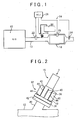
- FIG. 1 schematically shows the configuration of an exhaust gas control apparatus 14 to which a first embodiment of the invention is applied and which is provided in an exhaust pipe 12 of an engine 10 that is an internal combustion engine.
- the exhaust gas control apparatus 14 mainly includes a urea solution injection valve (injection valve) 16 provided at the exhaust pipe 12 of the engine 10 and a known selective catalytic reduction catalyst (catalyst) 18 provided in the exhaust pipe 12 at a position downstream of the urea solution injection valve 16.
- injection valve injection valve
- catalyst selective catalytic reduction catalyst
- the engine 10 which is an internal combustion engine mounted on a vehicle, is, for example, a four-stroke diesel engine that has four cylinders.
- the selective catalytic reduction catalyst 18 reduces (removes) nitrogen oxide (hereinafter, referred to as "NOx") in exhaust gas that flows in the exhaust pipe 12 by using ammonia (NH 3 ).
- NO is reduced to N 2 by, for example, the reaction, 4NO + 4NH 3 + O 2 ⁇ 4N 2 + H 2 O.
- NO 2 is reduced to N 2 by, for example, the reaction, 6NO 2 +8NH 3 ⁇ 7N 2 + 12H 2 O.
- NO and NO 2 are reduced to N 2 by, for example, the reaction, NO + NO 2 + 2NH 3 ⁇ 2N 2 + 3H 2 O.
- the SCR catalyst 18 has a function of storing NH 3 , and is formed of zeolite, for example.
- the urea solution injection valve 16 is provided in the exhaust pipe 12 at a position upstream of the SCR catalyst 18, and supplies an urea aqueous solution (hereinafter, referred to as "urea solution") as a reductant (additive) that is hydrolyzed to NH 3 .
- urea solution urea aqueous solution
- the urea solution stored in a urea solution tank 20 is injected from the urea solution injection valve 16 into the exhaust pipe 12 on the basis of a command.
- the injected urea solution is hydrolyzed with the use of the heat of exhaust gas, by, for example, the reaction, (NH 2 ) 2CO + H 2 O ⁇ 2NH 3 + CO 2 , and NH 3 is produced.
- a first NOx sensor 22 is provided in the exhaust pipe 12 at a position upstream of the urea solution injection valve 16 (at a position closer to the engine 10 than the urea solution injection valve 16), and detects the concentration of NOx in the exhaust gas that flows into the SCR catalyst 18.
- a second NOx sensor 24 is provided downstream of the SCR catalyst 18, and detects the concentration of NOx in the exhaust gas that flows out of the SCR catalyst 18.
- the SCR catalyst 18 is provided with a temperature sensor 26 that detects the bed temperature of the SCR catalyst 18. The data detected by these sensors are sent to an electronic control unit (ECU) 28.
- ECU electronice control unit
- the urea solution injection valve 16 is formed of a duty solenoid valve that adjusts the injection amount of urea solution on the basis of a change in the duty ratio of supplied current that is repeatedly turned on and off.
- the injection amount of urea solution is adjusted as needed on the basis of, for example, the amount of NOx that is estimated based on, for example, a rotational speed Ne of the engine 10 and an accelerator operation amount Acc, the concentration of NOx detected by the first NOx sensor 22, and the concentration of NOx detected by the second NOx sensor 24.
- FIG. 2 is an enlarged view of the urea solution injection valve 16 and its surroundings.
- the urea solution injection valve 16 is connected to the exhaust pipe 12 via a connecting pipe 30 that is connected to the exhaust pipe 12 and an injection valve holder 32 used to fix the urea solution injection valve 16 to the connecting pipe 30.
- the connecting pipe 30 is part of the exhaust pipe 12 because the connecting pipe 30 is connected to the exhaust pipe 12.
- the connecting pipe 30 may function as an exhaust pipe according to the invention.
- the injection valve holder 32 is a member used to fix (connect) the urea solution injection valve 16 to the connecting pipe 30 (the exhaust pipe 12).
- the injection valve holder 32 has a cylindrical holder portion 36 made of metal, such as steel or aluminum, a disc-shaped metal flange 38 that radially extends from one end of the holder portion 36, and metal cooling fins 40 that are fixedly fitted to the outer periphery of the holder portion 36.
- the flange 38 is a disc-shaped member that is fixedly provided at one end of the holder portion 36, which is on the connecting pipe 30 side in the axial direction of the holder portion 36, and that extends radially from the one end.
- the flange 38 is attached to the exhaust pipe 12 via the connecting pipe 30.
- a disc-shaped flange 42 is provided at an end of the connecting pipe 30.
- the flange 38 on the holder portion 36 side and the flange 42 on the connecting pipe 30 side are detachably fastened (connected) together with a bolt (not shown).
- the cooling fins 40 are formed of a plurality of thin rectangular metal plates, and are fixed to the outer periphery of the holder portion 36 so as to extend radially.
- the cooling fins 40 are disposed in a radial manner at equiangular intervals in the circumference direction of the holder portion 36.
- FIG. 3 is a view of the urea solution injection valve 16 and the injection valve holder 32 as viewed from the direction of an arrow A in FIG. 2 .
- four cooling fins 40 are disposed in a radial manner at equiangular intervals (of 90 degrees) so as to be in contact with the outer periphery of the holder portion 36.
- the cooling fins 40 are fixedly integrated with both the holder portion 36 and the flange 38.
- the cooling fins 40 are fixedly integrated with the holder portion 36 by, for example, welding at contact faces 46 and the cooling fins 40 are fixedly integrated with the flange 38 by, for example, welding at a contact face 48, as shown by the bold lines.
- the holder portion 36, flange 38 and the cooling fins 40 may be fixed together by being integrated with each other. Due to provision of the cooling fins 40, the heat of exhaust gas that is transferred to the injection valve holder 32 is dissipated from the cooling fins 40. As a result, it is possible to prevent damage to the urea solution injection valve 16 and the injection valve holder 32 due to their overheating.
- the cooling fins 40 also function as reinforcing ribs that increases the rigidity of the injection valve holder 32. If the exhaust pipe 12 vibrates during operation of the engine 10, the vibrations are transmitted toward the injection valve holder 32 via the connecting pipe 30 and the vibrations are amplified on the urea solution injection valve 16 side. If the injection valve holder 32 vibrates due to the amplified vibrations, the injection valve holder 32 is deflected, which may raise a possibility that the direction of a spray formed by the urea solution injection valve 16 fixed to the injection valve holder 32 will be offset from the proper direction or a possibility that sealing performance between the flanges 38, 42 will be reduced.
- the cooling fins 40 according to the present embodiment are fixedly integrated with both the holder portion 36 and the flange 38, the cooling fins 40 function as reinforcing ribs of the injection valve holder 32, thereby increasing the rigidity of the injection valve holder 32. Accordingly, deflection of the injection valve holder 32 due to vibrations is suppressed, and occurrence of the above-described problems is also suppressed. Note that the shape and the number of the cooling fins 40 are set in advance based on experiments or calculations such that overheating of the urea solution injection valve 16 is prevented by the cooling fins 40 and occurrence of the above-described problems due to the vibrations transmitted to the urea solution injection valve 16 and the injection valve holder 32 is suppressed.
- the cooling fins 40 are fixed to both the holder portion 36 and the flange 38, the cooling fins 40 serves not only the cooling (heat dissipating) function but also the function as reinforcing ribs. Therefore, the cooling fins 40 increase the rigidity of the injection valve holder 32, thereby making it possible to suppress occurrence of an offset of the direction of a spray formed by the urea solution injection valve 16 from the proper direction due to the deflection of the injection valve holder 32 and insufficient sealing performance between the flanges 38, 42.
- the holder portion 36 is formed in a cylindrical shape
- the cooling fins 40 are formed of a plurality of plates that extend radially outward from the outer periphery of the holder portion 36 and are disposed in a radial manner at equiangular intervals in the circumference direction of the holder portion 36.
- FIG. 4 is a view mainly showing the structure of an injection valve holder 62 used to fix a urea solution injection valve (injection valve) 60 according to the second embodiment of the invention to the connecting pipe 30 (exhaust pipe 12), FIG. 4 corresponding to FIG. 3 that shows the first embodiment.
- the schematic configuration of an overall exhaust gas control apparatus that includes the urea solution injection valve 60 is substantially the same as that of the exhaust gas control apparatus 14 in the first embodiment, the description thereof will be omitted.
- three cooling fins 64 are fixed to the holder portion 36 and the flange 38, and are disposed in a radial manner at equiangular intervals (of 120 degrees) in the circumference direction of the holder portion 36.
- the cooling fins 64 are fixedly integrated with both the holder portion 36 and the flange 38. Therefore, in the present embodiment as well, the cooling fins 64 serve not only the function of preventing overheating of the urea solution injection valve 60 and the injection valve holder 62 but also the function as reinforcing ribs for increasing the rigidity of the injection valve holder 62.
- the number of the cooling fins 64 is three, and therefore the number of components is smaller than that in the first embodiment. Note that the number of the cooling fins 64 may be further reduced as long as the cooling fins 64 prevents overheating and provides a rigidity that is high enough to suppress deflection due to vibrations.
- FIG. 5 is a view mainly showing the structure of an injection valve holder 72 used to fix a urea solution injection valve (injection valve) 70 according to a third embodiment of the invention to the connecting pipe 30 (exhaust pipe 12), FIG. 5 corresponding to FIG. 3 and FIG. 4 that show the first and second embodiments.
- the schematic configuration of an exhaust gas control apparatus that includes the urea solution injection valve 70 is substantially the same as that of the exhaust gas control apparatus 14 in the first embodiment, the description thereof will be omitted.
- eight cooling fins 74 are fixed to the holder portion 36 and the flange 38, and are disposed in a radial manner at equiangular intervals (of 45 degrees) in the circumference direction of the holder portion 36.
- the cooling fins 74 are fixedly integrated with both the holder portion 36 and the flange 38. Therefore, in the present embodiment as well, the cooling fins 74 serve not only the function of preventing overheating of the urea solution injection valve 70 and the injection valve holder 72 but also the function as reinforcing ribs for increasing the rigidity of the injection valve holder 72. In the present embodiment, eight cooling fins 74 are disposed in a radial manner. Therefore, the rigidity of the injection valve holder 72 and the heat dissipating effect (cooling effect) by the cooing fins 74 are both increased as compared with the above-described embodiments.
- the rigidity of the injection valve holder 72 and the heat dissipating effect produced by the cooing fins 74 are both increased as compared with the above-described embodiments because the number of the cooling fins 74 is larger than that in each of the above-described embodiments.
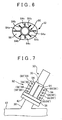
- FIG. 6 is a view mainly showing the structure of an injection valve holder 82 used to fix a urea solution injection valve (injection valve) 80 according to a fourth embodiment of the invention to the connecting pipe 30 (exhaust pipe 12), FIG. 6 corresponding to FIG. 3 to FIG. 5 that show the first to third embodiments.
- a flange 86 is formed in an oval shape, and the radial lengths of cooling fins 84 vary depending on portions where the cooling fins 84 are disposed.
- cooling fins 84a that are disposed so as to extend along the direction of the major axis of the flange 86 have the longest radial length
- cooling fins 84c that are disposed so as to extend along the direction of the minor axis of the flange 86 have the shortest radial length
- Cooling fins 84b that are disposed between the cooling fins 84a and cooling fins 84c in the circumferential direction of the injection valve holder 82 have a radial length intermediate between the radial length of the cooling fins 84a and the radial length of the cooling fins 84c.
- the rigidity of the portions to which the cooling fins 84a are fixed is higher than the rigidity of the portions to which the cooling fins 84c are fixed. That is, in the present embodiment, the rigidity of the injection valve holder 82 varies in the circumferential direction because the cooling fins 84 vary in size and shape depending on the portions where they are disposed.
- the cooling fins 84a are disposed at the portions where the amplitude of the vibrations transmitted to the injection valve holder 82 is large. That is, the cooling fins 84 disposed at portions at which the amplitude of vibrations is larger have a longer radial length and accordingly a higher rigidity is imparted to the portions at which the amplitude of vibrations is larger. Note that the portions of the injection valve holder 82 in the circumferential direction, at which the amplitude of vibrations is larger, are determined in advance based on experiments or calculations. Then, the sizes and shapes of the cooling fins 84 are set appropriately so that a higher rigidity is imparted to the portions at which the amplitude of vibrations is larger.
- the cooling fins 84 vary in size and shape depending on the portions of the injection valve holder 82, at which they are disposed. Specifically, the cooling fins 84 disposed at the portions at which the amplitude of vibrations is larger have a longer radial length. By disposing the cooling fins 84 having a greater length at the portions of the injection valve holder 82 in the circumferential direction, at which the amplitude of vibrations is larger, a higher rigidity is imparted to the portions at which the amplitude of vibrations is larger. Because the cooling fins 84 vary in size and shape depending on the amplitude of vibrations at the portions at which they are disposed as described above, the rigidity of the portions required to have a higher rigidity is efficiently increased.
- FIG. 7 is a view mainly showing the structure of an injection valve holder 92 used to fix a urea solution injection valve (injection valve) 90 according to a fifth embodiment of the invention to the connecting pipe 30 (exhaust pipe 12), FIG. 7 corresponding to FIG. 2 that shows the first embodiment.
- FIG. 7 corresponding to FIG. 2 that shows the first embodiment.
- Each cooling fin 94 according to the present embodiment has four through-holes 96 (that may function as holes in the invention). If the through-holes 96 are formed in the cooling fins 94, the flow of air around the cooling fins 94 becomes turbulent.
- the cooling fins 94 may have semispherical or columnar protrusions 96' instead of the through-holes 96. Because the flow of air is made turbulent also by the protrusions 96', the cooling effect produced by the cooling fins 94 is further enhanced.
- cooling fins 94 have the through-holes 96 or the protrusions 96', the flow of air around the cooling fins 94 is actively made turbulent. As a result, the cooling effect produced by the cooing fins 94 is further enhanced.
- the urea solution injection valves are described independently from each other. However, the above-described embodiments may be combined with each other as needed.
- the through-holes 96 may be formed in the cooling fins 74 in FIG. 5 .
- the urea solution injection valves are described.
- the invention may be applied as needed to a structure for injecting an aqueous solution other than a urea aqueous solution.
- the number of the cooling fins is three, four or eight.
- the number of the cooling fins may be changed as needed based on the cooling performance required of the cooling fins and the rigidity of the injection valve holder, which should be achieved by the cooling fins.
- the cooling fins are formed in a rectangular shape.
- the shape of the cooling fins is not limited to a rectangular shape, and may be a triangular shape, for example.
- each cooling fin is formed of a flat plate having a uniform thickness.
- the thickness of each cooling fin may vary in the radial direction of the holder portion or each cooling fin may be formed of a plate having a curved face. Even in such cases, the cooling fins are fixedly integrated with both the holder portion and the flange.
- each cooing fin is formed of a plate that extends from the outer periphery of the holder portion in the radial direction.
- the plates do not necessarily extend in the radial direction as long as they extend outward from the outer periphery of the holder portion, and the direction in which the plates extend may be changed as needed.
- the cooing fins are disposed in a radial manner at equiangular intervals in the circumference direction of the holder portion.
- the cooling fins are not necessarily disposed in a radial manner at equiangular intervals.
- the intervals between the cooling fins may be changed as needed.
- the number of the cooling fins may be larger at a portion of the holder portion, at which the amplitude of vibrations is larger.
- the number of the through-holes 96 or the protrusions 96' of the cooing fins 94 or the shapes of the through-holes 96 or the protrusions 96' of the cooling fins 94 may be changed as needed as long as the flow of air around the cooling fins is made turbulent.
- the SCR catalyst 18 is made of zeolite. However, another precious metal or the like may be used as an active component of the SCR catalyst 18.
- the cooing fins are fixed to the holder portion and the flange without any gap.
- a gap may be formed at part of the fixed portions as long as the cooling fins are fixed to both the holder portion and the flange.
- the urea solution injection valve 16 is formed of a duty solenoid valve.
- other valves that are able to adjust the injection amount of urea solution such as a linear solenoid valve, may be used as the urea solution injection valve 16.
- the urea solution injection valve and the injection valve holder are separate members. However, the urea solution injection valve and the injection valve holder may be formed to be integrated with each other. If the urea solution injection valve and the injection valve holder are formed to be integrated with each other, the cooling fins may extend to portions of the urea solution injection valve.
Landscapes
- Chemical & Material Sciences (AREA)
- Engineering & Computer Science (AREA)
- Chemical Kinetics & Catalysis (AREA)
- Health & Medical Sciences (AREA)
- Toxicology (AREA)
- Combustion & Propulsion (AREA)
- Mechanical Engineering (AREA)
- General Engineering & Computer Science (AREA)
- Exhaust Gas After Treatment (AREA)
Claims (13)
- Abgassteuerungseinrichtung für eine Brennkraftmaschine, wobei die Abgassteuerungseinrichtung ein Einspritzventil, welches an einem Abgasrohr einer Brennkraftmaschine vorgesehen ist, und einen Katalysator aufweist, der in dem Abgasrohr an einer stromabwärtigen Position des Einspritzventils vorgesehen ist, dadurch gekennzeichnet, dass:das Einspritzventil (16, 60, 70, 80, 90) an das Abgasrohr (12) über eine Einspritzventilhaltevorrichtung (32, 62, 72, 82, 92) befestigt ist, die einen rohrförmigen Haltevorrichtungsabschnitt (36), einen Flansch (38, 86), der an ein Ende des Haltevorrichtungsabschnitts (36) befestigt und an das Abgasrohr (12) angebracht ist, und eine Kühlrippe (40, 64, 74, 84, 94) aufweist, die an einen Außenumfang des Haltevorrichtungsabschnitts (36) befestigt ist, wobeidie Kühlrippe (40, 64, 74, 84, 94) an dem Haltevorrichtungsabschnitt (36) sowie an dem Flansch (38, 86) befestigt ist.
- Abgassteuerungseinrichtung für eine Brennkraftmaschine nach Anspruch 1, wobei eine Vielzahl von Kühlrippen (40, 64, 74, 84, 94) aus einer Vielzahl von Platten, welche von dem Außenumfang des Haltevorrichtungsabschnitts (36) nach außen verlaufen, ausgebildet ist.
- Abgassteuerungseinrichtung für eine Brennkraftmaschine nach Anspruch 2, wobei:der Haltevorrichtungsabschnitt (36) in einer zylindrischen Form ausgebildet ist;die Kühlrippen (40, 64, 74, 84, 94) aus einer Vielzahl von Platten ausgebildet sind, die von dem Außenumfang des Haltevorrichtungsabschnitts (36) in einer Radialrichtung des Haltevorrichtungsabschnitts (36) verlaufen; unddie Kühlrippen (40, 64, 74, 84, 94) radial mit gleichwinkligen Intervallen in einer Umfangsrichtung des Haltevorrichtungsabschnitts (36) angeordnet sind.
- Abgassteuerungseinrichtung für eine Brennkraftmaschine nach Anspruch 2 oder 3, wobei die Kühlrippen (84a, 84b, 84c) sich in einer Größe und einer Form abhängig von Abschnitten des Haltevorrichtungsabschnitts (36), an welchem die Kühlrippen angeordnet sind, unterscheiden.
- Abgassteuerungseinrichtung für eine Brennkraftmaschine nach Anspruch 4, wobei die Kühlrippen (84a, 84b, 84c) sich in einer Länge in einer Radialrichtung des Haltevorrichtungsabschnitts (36) in Abhängigkeit von Abschnitten des Haltevorrichtungsabschnitts (36), an welchem die Kühlrippen angeordnet sind, unterscheiden.
- Abgassteuerungseinrichtung für eine Brennkraftmaschine nach einem der Ansprüche 1 bis 5, wobei die Kühlrippe (94) eine Ausnehmung (96) oder einen Vorsprung (96') aufweist.
- Abgassteuerungseinrichtung für eine Brennkraftmaschine nach einem der Ansprüche 1 bis 6, wobei die Einspritzventilhaltevorrichtung (32, 62, 72, 82, 92) und das Einspritzventil (16, 60, 70, 80, 90) so ausgebildet sind, um miteinander integriert zu sein.
- Einspritzventilhaltevorrichtung, verwendet, um ein Einspritzventil, welches in einem Abgasrohr einer Brennkraftmaschine zum Zuführen eines Zusatzes in das Abgasrohr vorgesehen ist, an das Abgasrohr zu befestigen,
dadurch gekennzeichnet, dass
die Einspritzventilhaltevorrichtung (32, 62, 72, 82, 92) einen rohrförmigen Haltevorrichtungsabschnitt (36), einen Flansch (38, 86), der an ein Ende des Haltevorrichtungsabschnitts (36) befestigt ist und zum Anbringen an das Abgasrohr (12) geeignet ist, und eine Kühlrippe (40, 64, 74, 84, 94) aufweist, die an einen Außenumfang des Haltevorrichtungsabschnitts (36) befestigt ist, wobei
die Kühlrippe (40, 64, 74, 84, 94) an den Haltevorrichtungsabschnitt (36) und an den Flansch (38, 86) befestigt ist. - Einspritzventilhaltevorrichtung nach Anspruch 8, wobei eine Vielzahl von Kühlrippen (40, 64, 74, 84, 94) aus einer Vielzahl von Platten, welche von dem Außenumfang des Haltevorrichtungsabschnitts (36) nach außen verlaufen, ausgebildet sind.
- Einspritzventilhaltevorrichtung nach Anspruch 9, wobei
der Haltevorrichtungsabschnitt (36) in einer zylindrischen Form ausgebildet ist;
die Kühlrippen (40, 64, 74, 84, 94) aus einer Vielzahl von Platten ausgebildet sind, die von dem Außenumfang des Haltevorrichtungsabschnitts (36) in einer Radialrichtung des Haltevorrichtungsabschnitts (36) verlaufen; und
die Kühlrippen (40, 64, 74, 84, 94) radial mit gleichwinkligen Intervallen in einer Umfangsrichtung des Haltevorrichtungsabschnitts (36) angeordnet sind. - Einspritzventilhaltevorrichtung nach Anspruch 9 oder 10, wobei die Kühlrippen (84a, 84b, 84c) sich in einer Größe und einer Form abhängig von Abschnitten des Haltevorrichtungsabschnitts (36), an welchem die Kühlrippen angeordnet sind, unterscheiden.
- Einspritzventilhaltevorrichtung nach Anspruch 11, wobei die Kühlrippen (84a, 84b, 84c) sich in einer Länge in einer Radialrichtung des Haltevorrichtungsabschnitts (36) in Abhängigkeit von Abschnitten des Haltevorrichtungsabschnitts (36), an welchem die Kühlrippen angeordnet sind,
unterscheiden. - Einspritzventilhaltevorrichtung nach einem der Ansprüche 8 bis 12, wobei die Kühlrippe (94) eine Ausnehmung (96) oder einen Vorsprung (96') aufweist.
Applications Claiming Priority (1)
| Application Number | Priority Date | Filing Date | Title |
|---|---|---|---|
| JP2012095146A JP5704110B2 (ja) | 2012-04-18 | 2012-04-18 | 内燃機関の排気浄化装置および添加弁ホルダ |
Publications (2)
| Publication Number | Publication Date |
|---|---|
| EP2653685A1 EP2653685A1 (de) | 2013-10-23 |
| EP2653685B1 true EP2653685B1 (de) | 2015-01-14 |
Family
ID=48092768
Family Applications (1)
| Application Number | Title | Priority Date | Filing Date |
|---|---|---|---|
| EP13163402.4A Not-in-force EP2653685B1 (de) | 2012-04-18 | 2013-04-11 | Abgaskontrollvorrichtung für Verbrennungsmotor und Einspritzventilhalter |
Country Status (2)
| Country | Link |
|---|---|
| EP (1) | EP2653685B1 (de) |
| JP (1) | JP5704110B2 (de) |
Families Citing this family (5)
| Publication number | Priority date | Publication date | Assignee | Title |
|---|---|---|---|---|
| CN105986860B (zh) * | 2015-01-30 | 2019-07-23 | 天纳克(苏州)排放系统有限公司 | 计量泵嘴及其发动机排气后处理系统 |
| JP2016176341A (ja) * | 2015-03-18 | 2016-10-06 | トヨタ自動車株式会社 | 内燃機関の排気処理装置 |
| KR101815770B1 (ko) * | 2016-06-30 | 2018-01-05 | 주식회사 현대케피코 | 요소수 인젝터 모듈 |
| CN109372615A (zh) * | 2018-12-06 | 2019-02-22 | 宁波安创电子科技有限公司 | 一种具有散热防护罩的尿素喷嘴 |
| DE102020126726B4 (de) | 2020-10-12 | 2024-12-24 | Dr. Ing. H.C. F. Porsche Aktiengesellschaft | Montagevorrichtung für ein Einspritzventil eines Abgasbehandlungssystems eines Kraftfahrzeugs |
Family Cites Families (7)
| Publication number | Priority date | Publication date | Assignee | Title |
|---|---|---|---|---|
| JP2005264756A (ja) * | 2004-03-16 | 2005-09-29 | Toyota Industries Corp | 排気浄化装置 |
| JP2009041370A (ja) * | 2007-08-06 | 2009-02-26 | Bosch Corp | 内燃機関の排気浄化装置 |
| JP2009138627A (ja) * | 2007-12-06 | 2009-06-25 | Hino Motors Ltd | 尿素水添加ノズル |
| DE602008000877D1 (de) * | 2008-03-28 | 2010-05-06 | Magneti Marelli Spa | Haltevorrichtung für einen Injektor in einem Abgassystem einer Brennkraftmaschine |
| US20090266343A1 (en) * | 2008-04-25 | 2009-10-29 | Lecca Oscar A | Thick film resistor fuel vaporizer |
| DE102009027185A1 (de) * | 2009-06-25 | 2010-12-30 | Robert Bosch Gmbh | Dosiervorrichtung zur Nachbehandlung von Abgasen |
| US20110099974A1 (en) * | 2009-11-03 | 2011-05-05 | International Engine Intellectual Property Company Llc | Reductant spray injector boss |
-
2012
- 2012-04-18 JP JP2012095146A patent/JP5704110B2/ja not_active Expired - Fee Related
-
2013
- 2013-04-11 EP EP13163402.4A patent/EP2653685B1/de not_active Not-in-force
Also Published As
| Publication number | Publication date |
|---|---|
| EP2653685A1 (de) | 2013-10-23 |
| JP2013221475A (ja) | 2013-10-28 |
| JP5704110B2 (ja) | 2015-04-22 |
Similar Documents
| Publication | Publication Date | Title |
|---|---|---|
| EP2653685B1 (de) | Abgaskontrollvorrichtung für Verbrennungsmotor und Einspritzventilhalter | |
| US8776509B2 (en) | Tri-flow exhaust treatment device with reductant mixing tube | |
| EP3030767B1 (de) | Verfahren, vorrichtung und system zur nachbehandlung von abgasen | |
| JP6009260B2 (ja) | 排気浄化装置 | |
| EP2423479A2 (de) | Abgasreinigungsvorrichtung | |
| EP1715153A1 (de) | Scr-schalldämpfer | |
| CN106194343B (zh) | 还原剂喷射器用垫片以及废气后处理装置 | |
| US9593613B2 (en) | Recessed exhaust reductant injector with cover plate | |
| EP2573349A1 (de) | Auspuffrohr | |
| KR20150111191A (ko) | 열전달부재를 구비하는 선택적 촉매 환원 시스템의 요소저장탱크 및 이를 구비하는 농업용 작업차량 | |
| JP6769153B2 (ja) | 内燃機関の排ガス浄化装置 | |
| JP2007071161A (ja) | 内燃機関の排気浄化装置 | |
| KR101484406B1 (ko) | 차량용 배기가스 정화장치 | |
| JP7428176B2 (ja) | 排気構造およびインジェクタ取付部材 | |
| JP5787082B2 (ja) | 添加弁シール構造 | |
| CN111742122A (zh) | 还原剂喷射装置 | |
| JP7310676B2 (ja) | ミキサー | |
| JP5569667B2 (ja) | 排気浄化装置 | |
| JP7314840B2 (ja) | 排気構造 | |
| US20250376936A1 (en) | Doser mount for exhaust aftertreatment system | |
| JP5020028B2 (ja) | 排気浄化装置 | |
| US10400646B2 (en) | Diesel exhaust fluid system | |
| WO2020189577A1 (ja) | ミキサー部材 | |
| JP2020190233A (ja) | ブラケット | |
| JP2020193597A (ja) | 排気システム |
Legal Events
| Date | Code | Title | Description |
|---|---|---|---|
| PUAI | Public reference made under article 153(3) epc to a published international application that has entered the european phase |
Free format text: ORIGINAL CODE: 0009012 |
|
| 17P | Request for examination filed |
Effective date: 20130411 |
|
| AK | Designated contracting states |
Kind code of ref document: A1 Designated state(s): AL AT BE BG CH CY CZ DE DK EE ES FI FR GB GR HR HU IE IS IT LI LT LU LV MC MK MT NL NO PL PT RO RS SE SI SK SM TR |
|
| AX | Request for extension of the european patent |
Extension state: BA ME |
|
| GRAP | Despatch of communication of intention to grant a patent |
Free format text: ORIGINAL CODE: EPIDOSNIGR1 |
|
| RIC1 | Information provided on ipc code assigned before grant |
Ipc: F01N 3/20 20060101AFI20140721BHEP |
|
| INTG | Intention to grant announced |
Effective date: 20140818 |
|
| GRAS | Grant fee paid |
Free format text: ORIGINAL CODE: EPIDOSNIGR3 |
|
| GRAA | (expected) grant |
Free format text: ORIGINAL CODE: 0009210 |
|
| RIN1 | Information on inventor provided before grant (corrected) |
Inventor name: AOYAGI, YUSUKE |
|
| RAP1 | Party data changed (applicant data changed or rights of an application transferred) |
Owner name: TOYOTA JIDOSHA KABUSHIKI KAISHA |
|
| AK | Designated contracting states |
Kind code of ref document: B1 Designated state(s): AL AT BE BG CH CY CZ DE DK EE ES FI FR GB GR HR HU IE IS IT LI LT LU LV MC MK MT NL NO PL PT RO RS SE SI SK SM TR |
|
| REG | Reference to a national code |
Ref country code: GB Ref legal event code: FG4D |
|
| REG | Reference to a national code |
Ref country code: CH Ref legal event code: EP |
|
| REG | Reference to a national code |
Ref country code: IE Ref legal event code: FG4D |
|
| REG | Reference to a national code |
Ref country code: AT Ref legal event code: REF Ref document number: 707185 Country of ref document: AT Kind code of ref document: T Effective date: 20150215 |
|
| REG | Reference to a national code |
Ref country code: DE Ref legal event code: R096 Ref document number: 602013000831 Country of ref document: DE Effective date: 20150305 |
|
| REG | Reference to a national code |
Ref country code: NL Ref legal event code: VDEP Effective date: 20150114 |
|
| REG | Reference to a national code |
Ref country code: AT Ref legal event code: MK05 Ref document number: 707185 Country of ref document: AT Kind code of ref document: T Effective date: 20150114 |
|
| REG | Reference to a national code |
Ref country code: LT Ref legal event code: MG4D |
|
| PG25 | Lapsed in a contracting state [announced via postgrant information from national office to epo] |
Ref country code: HR Free format text: LAPSE BECAUSE OF FAILURE TO SUBMIT A TRANSLATION OF THE DESCRIPTION OR TO PAY THE FEE WITHIN THE PRESCRIBED TIME-LIMIT Effective date: 20150114 Ref country code: FI Free format text: LAPSE BECAUSE OF FAILURE TO SUBMIT A TRANSLATION OF THE DESCRIPTION OR TO PAY THE FEE WITHIN THE PRESCRIBED TIME-LIMIT Effective date: 20150114 Ref country code: BG Free format text: LAPSE BECAUSE OF FAILURE TO SUBMIT A TRANSLATION OF THE DESCRIPTION OR TO PAY THE FEE WITHIN THE PRESCRIBED TIME-LIMIT Effective date: 20150414 Ref country code: LT Free format text: LAPSE BECAUSE OF FAILURE TO SUBMIT A TRANSLATION OF THE DESCRIPTION OR TO PAY THE FEE WITHIN THE PRESCRIBED TIME-LIMIT Effective date: 20150114 Ref country code: SE Free format text: LAPSE BECAUSE OF FAILURE TO SUBMIT A TRANSLATION OF THE DESCRIPTION OR TO PAY THE FEE WITHIN THE PRESCRIBED TIME-LIMIT Effective date: 20150114 Ref country code: ES Free format text: LAPSE BECAUSE OF FAILURE TO SUBMIT A TRANSLATION OF THE DESCRIPTION OR TO PAY THE FEE WITHIN THE PRESCRIBED TIME-LIMIT Effective date: 20150114 Ref country code: NO Free format text: LAPSE BECAUSE OF FAILURE TO SUBMIT A TRANSLATION OF THE DESCRIPTION OR TO PAY THE FEE WITHIN THE PRESCRIBED TIME-LIMIT Effective date: 20150414 |
|
| PG25 | Lapsed in a contracting state [announced via postgrant information from national office to epo] |
Ref country code: PL Free format text: LAPSE BECAUSE OF FAILURE TO SUBMIT A TRANSLATION OF THE DESCRIPTION OR TO PAY THE FEE WITHIN THE PRESCRIBED TIME-LIMIT Effective date: 20150114 Ref country code: AT Free format text: LAPSE BECAUSE OF FAILURE TO SUBMIT A TRANSLATION OF THE DESCRIPTION OR TO PAY THE FEE WITHIN THE PRESCRIBED TIME-LIMIT Effective date: 20150114 Ref country code: LV Free format text: LAPSE BECAUSE OF FAILURE TO SUBMIT A TRANSLATION OF THE DESCRIPTION OR TO PAY THE FEE WITHIN THE PRESCRIBED TIME-LIMIT Effective date: 20150114 Ref country code: RS Free format text: LAPSE BECAUSE OF FAILURE TO SUBMIT A TRANSLATION OF THE DESCRIPTION OR TO PAY THE FEE WITHIN THE PRESCRIBED TIME-LIMIT Effective date: 20150114 Ref country code: NL Free format text: LAPSE BECAUSE OF FAILURE TO SUBMIT A TRANSLATION OF THE DESCRIPTION OR TO PAY THE FEE WITHIN THE PRESCRIBED TIME-LIMIT Effective date: 20150114 Ref country code: IS Free format text: LAPSE BECAUSE OF FAILURE TO SUBMIT A TRANSLATION OF THE DESCRIPTION OR TO PAY THE FEE WITHIN THE PRESCRIBED TIME-LIMIT Effective date: 20150514 Ref country code: GR Free format text: LAPSE BECAUSE OF FAILURE TO SUBMIT A TRANSLATION OF THE DESCRIPTION OR TO PAY THE FEE WITHIN THE PRESCRIBED TIME-LIMIT Effective date: 20150415 |
|
| REG | Reference to a national code |
Ref country code: DE Ref legal event code: R097 Ref document number: 602013000831 Country of ref document: DE |
|
| PG25 | Lapsed in a contracting state [announced via postgrant information from national office to epo] |
Ref country code: RO Free format text: LAPSE BECAUSE OF FAILURE TO SUBMIT A TRANSLATION OF THE DESCRIPTION OR TO PAY THE FEE WITHIN THE PRESCRIBED TIME-LIMIT Effective date: 20150114 Ref country code: CZ Free format text: LAPSE BECAUSE OF FAILURE TO SUBMIT A TRANSLATION OF THE DESCRIPTION OR TO PAY THE FEE WITHIN THE PRESCRIBED TIME-LIMIT Effective date: 20150114 Ref country code: EE Free format text: LAPSE BECAUSE OF FAILURE TO SUBMIT A TRANSLATION OF THE DESCRIPTION OR TO PAY THE FEE WITHIN THE PRESCRIBED TIME-LIMIT Effective date: 20150114 Ref country code: DK Free format text: LAPSE BECAUSE OF FAILURE TO SUBMIT A TRANSLATION OF THE DESCRIPTION OR TO PAY THE FEE WITHIN THE PRESCRIBED TIME-LIMIT Effective date: 20150114 Ref country code: SK Free format text: LAPSE BECAUSE OF FAILURE TO SUBMIT A TRANSLATION OF THE DESCRIPTION OR TO PAY THE FEE WITHIN THE PRESCRIBED TIME-LIMIT Effective date: 20150114 |
|
| PLBE | No opposition filed within time limit |
Free format text: ORIGINAL CODE: 0009261 |
|
| STAA | Information on the status of an ep patent application or granted ep patent |
Free format text: STATUS: NO OPPOSITION FILED WITHIN TIME LIMIT |
|
| PG25 | Lapsed in a contracting state [announced via postgrant information from national office to epo] |
Ref country code: LU Free format text: LAPSE BECAUSE OF FAILURE TO SUBMIT A TRANSLATION OF THE DESCRIPTION OR TO PAY THE FEE WITHIN THE PRESCRIBED TIME-LIMIT Effective date: 20150411 Ref country code: MC Free format text: LAPSE BECAUSE OF FAILURE TO SUBMIT A TRANSLATION OF THE DESCRIPTION OR TO PAY THE FEE WITHIN THE PRESCRIBED TIME-LIMIT Effective date: 20150114 |
|
| 26N | No opposition filed |
Effective date: 20151015 |
|
| PG25 | Lapsed in a contracting state [announced via postgrant information from national office to epo] |
Ref country code: IT Free format text: LAPSE BECAUSE OF FAILURE TO SUBMIT A TRANSLATION OF THE DESCRIPTION OR TO PAY THE FEE WITHIN THE PRESCRIBED TIME-LIMIT Effective date: 20150114 |
|
| REG | Reference to a national code |
Ref country code: DE Ref legal event code: R084 Ref document number: 602013000831 Country of ref document: DE |
|
| REG | Reference to a national code |
Ref country code: IE Ref legal event code: MM4A |
|
| REG | Reference to a national code |
Ref country code: GB Ref legal event code: 746 Effective date: 20160120 |
|
| PG25 | Lapsed in a contracting state [announced via postgrant information from national office to epo] |
Ref country code: SI Free format text: LAPSE BECAUSE OF FAILURE TO SUBMIT A TRANSLATION OF THE DESCRIPTION OR TO PAY THE FEE WITHIN THE PRESCRIBED TIME-LIMIT Effective date: 20150114 |
|
| REG | Reference to a national code |
Ref country code: FR Ref legal event code: PLFP Year of fee payment: 4 |
|
| PG25 | Lapsed in a contracting state [announced via postgrant information from national office to epo] |
Ref country code: IE Free format text: LAPSE BECAUSE OF NON-PAYMENT OF DUE FEES Effective date: 20150411 |
|
| PG25 | Lapsed in a contracting state [announced via postgrant information from national office to epo] |
Ref country code: BE Free format text: LAPSE BECAUSE OF FAILURE TO SUBMIT A TRANSLATION OF THE DESCRIPTION OR TO PAY THE FEE WITHIN THE PRESCRIBED TIME-LIMIT Effective date: 20150114 |
|
| REG | Reference to a national code |
Ref country code: CH Ref legal event code: PL |
|
| PG25 | Lapsed in a contracting state [announced via postgrant information from national office to epo] |
Ref country code: MT Free format text: LAPSE BECAUSE OF FAILURE TO SUBMIT A TRANSLATION OF THE DESCRIPTION OR TO PAY THE FEE WITHIN THE PRESCRIBED TIME-LIMIT Effective date: 20150114 |
|
| PG25 | Lapsed in a contracting state [announced via postgrant information from national office to epo] |
Ref country code: CH Free format text: LAPSE BECAUSE OF NON-PAYMENT OF DUE FEES Effective date: 20160430 Ref country code: LI Free format text: LAPSE BECAUSE OF NON-PAYMENT OF DUE FEES Effective date: 20160430 |
|
| REG | Reference to a national code |
Ref country code: FR Ref legal event code: PLFP Year of fee payment: 5 |
|
| PG25 | Lapsed in a contracting state [announced via postgrant information from national office to epo] |
Ref country code: HU Free format text: LAPSE BECAUSE OF FAILURE TO SUBMIT A TRANSLATION OF THE DESCRIPTION OR TO PAY THE FEE WITHIN THE PRESCRIBED TIME-LIMIT; INVALID AB INITIO Effective date: 20130411 |
|
| PG25 | Lapsed in a contracting state [announced via postgrant information from national office to epo] |
Ref country code: CY Free format text: LAPSE BECAUSE OF FAILURE TO SUBMIT A TRANSLATION OF THE DESCRIPTION OR TO PAY THE FEE WITHIN THE PRESCRIBED TIME-LIMIT Effective date: 20150114 |
|
| PG25 | Lapsed in a contracting state [announced via postgrant information from national office to epo] |
Ref country code: TR Free format text: LAPSE BECAUSE OF FAILURE TO SUBMIT A TRANSLATION OF THE DESCRIPTION OR TO PAY THE FEE WITHIN THE PRESCRIBED TIME-LIMIT Effective date: 20150114 |
|
| REG | Reference to a national code |
Ref country code: FR Ref legal event code: PLFP Year of fee payment: 6 |
|
| PG25 | Lapsed in a contracting state [announced via postgrant information from national office to epo] |
Ref country code: SM Free format text: LAPSE BECAUSE OF FAILURE TO SUBMIT A TRANSLATION OF THE DESCRIPTION OR TO PAY THE FEE WITHIN THE PRESCRIBED TIME-LIMIT Effective date: 20150114 |
|
| PG25 | Lapsed in a contracting state [announced via postgrant information from national office to epo] |
Ref country code: MK Free format text: LAPSE BECAUSE OF FAILURE TO SUBMIT A TRANSLATION OF THE DESCRIPTION OR TO PAY THE FEE WITHIN THE PRESCRIBED TIME-LIMIT Effective date: 20150114 Ref country code: PT Free format text: LAPSE BECAUSE OF FAILURE TO SUBMIT A TRANSLATION OF THE DESCRIPTION OR TO PAY THE FEE WITHIN THE PRESCRIBED TIME-LIMIT Effective date: 20150114 |
|
| PG25 | Lapsed in a contracting state [announced via postgrant information from national office to epo] |
Ref country code: AL Free format text: LAPSE BECAUSE OF FAILURE TO SUBMIT A TRANSLATION OF THE DESCRIPTION OR TO PAY THE FEE WITHIN THE PRESCRIBED TIME-LIMIT Effective date: 20150114 |
|
| PGFP | Annual fee paid to national office [announced via postgrant information from national office to epo] |
Ref country code: FR Payment date: 20190313 Year of fee payment: 7 |
|
| PGFP | Annual fee paid to national office [announced via postgrant information from national office to epo] |
Ref country code: DE Payment date: 20190326 Year of fee payment: 7 |
|
| PGFP | Annual fee paid to national office [announced via postgrant information from national office to epo] |
Ref country code: GB Payment date: 20190410 Year of fee payment: 7 |
|
| REG | Reference to a national code |
Ref country code: DE Ref legal event code: R119 Ref document number: 602013000831 Country of ref document: DE |
|
| PG25 | Lapsed in a contracting state [announced via postgrant information from national office to epo] |
Ref country code: FR Free format text: LAPSE BECAUSE OF NON-PAYMENT OF DUE FEES Effective date: 20200430 Ref country code: DE Free format text: LAPSE BECAUSE OF NON-PAYMENT OF DUE FEES Effective date: 20201103 |
|
| GBPC | Gb: european patent ceased through non-payment of renewal fee |
Effective date: 20200411 |
|
| PG25 | Lapsed in a contracting state [announced via postgrant information from national office to epo] |
Ref country code: GB Free format text: LAPSE BECAUSE OF NON-PAYMENT OF DUE FEES Effective date: 20200411 |