EP2653643A1 - Türbetätiger mit haptischem Feedback - Google Patents
Türbetätiger mit haptischem Feedback Download PDFInfo
- Publication number
- EP2653643A1 EP2653643A1 EP13001629.8A EP13001629A EP2653643A1 EP 2653643 A1 EP2653643 A1 EP 2653643A1 EP 13001629 A EP13001629 A EP 13001629A EP 2653643 A1 EP2653643 A1 EP 2653643A1
- Authority
- EP
- European Patent Office
- Prior art keywords
- door
- movement
- obstacle
- sensor
- user
- Prior art date
- Legal status (The legal status is an assumption and is not a legal conclusion. Google has not performed a legal analysis and makes no representation as to the accuracy of the status listed.)
- Withdrawn
Links
- 238000000034 method Methods 0.000 claims abstract description 15
- 238000013016 damping Methods 0.000 claims description 27
- 239000012530 fluid Substances 0.000 claims description 7
- 230000001419 dependent effect Effects 0.000 claims description 2
- 238000001514 detection method Methods 0.000 description 6
- 238000013519 translation Methods 0.000 description 5
- 238000013459 approach Methods 0.000 description 1
- 238000006243 chemical reaction Methods 0.000 description 1
- 230000003247 decreasing effect Effects 0.000 description 1
- 238000011161 development Methods 0.000 description 1
- 230000018109 developmental process Effects 0.000 description 1
- 230000005489 elastic deformation Effects 0.000 description 1
- 238000004146 energy storage Methods 0.000 description 1
- 238000004519 manufacturing process Methods 0.000 description 1
- 238000012544 monitoring process Methods 0.000 description 1
Images

Classifications
-
- E—FIXED CONSTRUCTIONS
- E05—LOCKS; KEYS; WINDOW OR DOOR FITTINGS; SAFES
- E05F—DEVICES FOR MOVING WINGS INTO OPEN OR CLOSED POSITION; CHECKS FOR WINGS; WING FITTINGS NOT OTHERWISE PROVIDED FOR, CONCERNED WITH THE FUNCTIONING OF THE WING
- E05F15/00—Power-operated mechanisms for wings
- E05F15/60—Power-operated mechanisms for wings using electrical actuators
- E05F15/603—Power-operated mechanisms for wings using electrical actuators using rotary electromotors
- E05F15/611—Power-operated mechanisms for wings using electrical actuators using rotary electromotors for swinging wings
- E05F15/63—Power-operated mechanisms for wings using electrical actuators using rotary electromotors for swinging wings operated by swinging arms
-
- E—FIXED CONSTRUCTIONS
- E05—LOCKS; KEYS; WINDOW OR DOOR FITTINGS; SAFES
- E05F—DEVICES FOR MOVING WINGS INTO OPEN OR CLOSED POSITION; CHECKS FOR WINGS; WING FITTINGS NOT OTHERWISE PROVIDED FOR, CONCERNED WITH THE FUNCTIONING OF THE WING
- E05F15/00—Power-operated mechanisms for wings
- E05F15/40—Safety devices, e.g. detection of obstructions or end positions
- E05F15/42—Detection using safety edges
- E05F15/43—Detection using safety edges responsive to disruption of energy beams, e.g. light or sound
-
- E—FIXED CONSTRUCTIONS
- E05—LOCKS; KEYS; WINDOW OR DOOR FITTINGS; SAFES
- E05F—DEVICES FOR MOVING WINGS INTO OPEN OR CLOSED POSITION; CHECKS FOR WINGS; WING FITTINGS NOT OTHERWISE PROVIDED FOR, CONCERNED WITH THE FUNCTIONING OF THE WING
- E05F3/00—Closers or openers with braking devices, e.g. checks; Construction of pneumatic or liquid braking devices
- E05F3/22—Additional arrangements for closers, e.g. for holding the wing in opened or other position
-
- E—FIXED CONSTRUCTIONS
- E05—LOCKS; KEYS; WINDOW OR DOOR FITTINGS; SAFES
- E05F—DEVICES FOR MOVING WINGS INTO OPEN OR CLOSED POSITION; CHECKS FOR WINGS; WING FITTINGS NOT OTHERWISE PROVIDED FOR, CONCERNED WITH THE FUNCTIONING OF THE WING
- E05F15/00—Power-operated mechanisms for wings
- E05F15/70—Power-operated mechanisms for wings with automatic actuation
-
- E—FIXED CONSTRUCTIONS
- E05—LOCKS; KEYS; WINDOW OR DOOR FITTINGS; SAFES
- E05F—DEVICES FOR MOVING WINGS INTO OPEN OR CLOSED POSITION; CHECKS FOR WINGS; WING FITTINGS NOT OTHERWISE PROVIDED FOR, CONCERNED WITH THE FUNCTIONING OF THE WING
- E05F15/00—Power-operated mechanisms for wings
- E05F15/40—Safety devices, e.g. detection of obstructions or end positions
- E05F15/42—Detection using safety edges
- E05F2015/483—Detection using safety edges for detection during opening
-
- E—FIXED CONSTRUCTIONS
- E05—LOCKS; KEYS; WINDOW OR DOOR FITTINGS; SAFES
- E05Y—INDEXING SCHEME ASSOCIATED WITH SUBCLASSES E05D AND E05F, RELATING TO CONSTRUCTION ELEMENTS, ELECTRIC CONTROL, POWER SUPPLY, POWER SIGNAL OR TRANSMISSION, USER INTERFACES, MOUNTING OR COUPLING, DETAILS, ACCESSORIES, AUXILIARY OPERATIONS NOT OTHERWISE PROVIDED FOR, APPLICATION THEREOF
- E05Y2201/00—Constructional elements; Accessories therefor
- E05Y2201/20—Brakes; Disengaging means; Holders; Stops; Valves; Accessories therefor
-
- E—FIXED CONSTRUCTIONS
- E05—LOCKS; KEYS; WINDOW OR DOOR FITTINGS; SAFES
- E05Y—INDEXING SCHEME ASSOCIATED WITH SUBCLASSES E05D AND E05F, RELATING TO CONSTRUCTION ELEMENTS, ELECTRIC CONTROL, POWER SUPPLY, POWER SIGNAL OR TRANSMISSION, USER INTERFACES, MOUNTING OR COUPLING, DETAILS, ACCESSORIES, AUXILIARY OPERATIONS NOT OTHERWISE PROVIDED FOR, APPLICATION THEREOF
- E05Y2201/00—Constructional elements; Accessories therefor
- E05Y2201/20—Brakes; Disengaging means; Holders; Stops; Valves; Accessories therefor
- E05Y2201/23—Actuation thereof
- E05Y2201/246—Actuation thereof by auxiliary motors, magnets, springs or weights
-
- E—FIXED CONSTRUCTIONS
- E05—LOCKS; KEYS; WINDOW OR DOOR FITTINGS; SAFES
- E05Y—INDEXING SCHEME ASSOCIATED WITH SUBCLASSES E05D AND E05F, RELATING TO CONSTRUCTION ELEMENTS, ELECTRIC CONTROL, POWER SUPPLY, POWER SIGNAL OR TRANSMISSION, USER INTERFACES, MOUNTING OR COUPLING, DETAILS, ACCESSORIES, AUXILIARY OPERATIONS NOT OTHERWISE PROVIDED FOR, APPLICATION THEREOF
- E05Y2201/00—Constructional elements; Accessories therefor
- E05Y2201/40—Motors; Magnets; Springs; Weights; Accessories therefor
- E05Y2201/404—Function thereof
- E05Y2201/41—Function thereof for closing
-
- E—FIXED CONSTRUCTIONS
- E05—LOCKS; KEYS; WINDOW OR DOOR FITTINGS; SAFES
- E05Y—INDEXING SCHEME ASSOCIATED WITH SUBCLASSES E05D AND E05F, RELATING TO CONSTRUCTION ELEMENTS, ELECTRIC CONTROL, POWER SUPPLY, POWER SIGNAL OR TRANSMISSION, USER INTERFACES, MOUNTING OR COUPLING, DETAILS, ACCESSORIES, AUXILIARY OPERATIONS NOT OTHERWISE PROVIDED FOR, APPLICATION THEREOF
- E05Y2201/00—Constructional elements; Accessories therefor
- E05Y2201/40—Motors; Magnets; Springs; Weights; Accessories therefor
- E05Y2201/43—Motors
- E05Y2201/434—Electromotors; Details thereof
-
- E—FIXED CONSTRUCTIONS
- E05—LOCKS; KEYS; WINDOW OR DOOR FITTINGS; SAFES
- E05Y—INDEXING SCHEME ASSOCIATED WITH SUBCLASSES E05D AND E05F, RELATING TO CONSTRUCTION ELEMENTS, ELECTRIC CONTROL, POWER SUPPLY, POWER SIGNAL OR TRANSMISSION, USER INTERFACES, MOUNTING OR COUPLING, DETAILS, ACCESSORIES, AUXILIARY OPERATIONS NOT OTHERWISE PROVIDED FOR, APPLICATION THEREOF
- E05Y2400/00—Electronic control; Electrical power; Power supply; Power or signal transmission; User interfaces
- E05Y2400/10—Electronic control
- E05Y2400/30—Electronic control of motors
- E05Y2400/3013—Electronic control of motors during manual wing operation
- E05Y2400/3015—Power assistance
-
- E—FIXED CONSTRUCTIONS
- E05—LOCKS; KEYS; WINDOW OR DOOR FITTINGS; SAFES
- E05Y—INDEXING SCHEME ASSOCIATED WITH SUBCLASSES E05D AND E05F, RELATING TO CONSTRUCTION ELEMENTS, ELECTRIC CONTROL, POWER SUPPLY, POWER SIGNAL OR TRANSMISSION, USER INTERFACES, MOUNTING OR COUPLING, DETAILS, ACCESSORIES, AUXILIARY OPERATIONS NOT OTHERWISE PROVIDED FOR, APPLICATION THEREOF
- E05Y2400/00—Electronic control; Electrical power; Power supply; Power or signal transmission; User interfaces
- E05Y2400/10—Electronic control
- E05Y2400/45—Control modes
-
- E—FIXED CONSTRUCTIONS
- E05—LOCKS; KEYS; WINDOW OR DOOR FITTINGS; SAFES
- E05Y—INDEXING SCHEME ASSOCIATED WITH SUBCLASSES E05D AND E05F, RELATING TO CONSTRUCTION ELEMENTS, ELECTRIC CONTROL, POWER SUPPLY, POWER SIGNAL OR TRANSMISSION, USER INTERFACES, MOUNTING OR COUPLING, DETAILS, ACCESSORIES, AUXILIARY OPERATIONS NOT OTHERWISE PROVIDED FOR, APPLICATION THEREOF
- E05Y2400/00—Electronic control; Electrical power; Power supply; Power or signal transmission; User interfaces
- E05Y2400/10—Electronic control
- E05Y2400/52—Safety arrangements associated with the wing motor
- E05Y2400/53—Wing impact prevention or reduction
- E05Y2400/532—Emergency braking or blocking
-
- E—FIXED CONSTRUCTIONS
- E05—LOCKS; KEYS; WINDOW OR DOOR FITTINGS; SAFES
- E05Y—INDEXING SCHEME ASSOCIATED WITH SUBCLASSES E05D AND E05F, RELATING TO CONSTRUCTION ELEMENTS, ELECTRIC CONTROL, POWER SUPPLY, POWER SIGNAL OR TRANSMISSION, USER INTERFACES, MOUNTING OR COUPLING, DETAILS, ACCESSORIES, AUXILIARY OPERATIONS NOT OTHERWISE PROVIDED FOR, APPLICATION THEREOF
- E05Y2400/00—Electronic control; Electrical power; Power supply; Power or signal transmission; User interfaces
- E05Y2400/10—Electronic control
- E05Y2400/52—Safety arrangements associated with the wing motor
- E05Y2400/53—Wing impact prevention or reduction
- E05Y2400/54—Obstruction or resistance detection
-
- E—FIXED CONSTRUCTIONS
- E05—LOCKS; KEYS; WINDOW OR DOOR FITTINGS; SAFES
- E05Y—INDEXING SCHEME ASSOCIATED WITH SUBCLASSES E05D AND E05F, RELATING TO CONSTRUCTION ELEMENTS, ELECTRIC CONTROL, POWER SUPPLY, POWER SIGNAL OR TRANSMISSION, USER INTERFACES, MOUNTING OR COUPLING, DETAILS, ACCESSORIES, AUXILIARY OPERATIONS NOT OTHERWISE PROVIDED FOR, APPLICATION THEREOF
- E05Y2400/00—Electronic control; Electrical power; Power supply; Power or signal transmission; User interfaces
- E05Y2400/80—User interfaces
- E05Y2400/81—Feedback to user, e.g. tactile
-
- E—FIXED CONSTRUCTIONS
- E05—LOCKS; KEYS; WINDOW OR DOOR FITTINGS; SAFES
- E05Y—INDEXING SCHEME ASSOCIATED WITH SUBCLASSES E05D AND E05F, RELATING TO CONSTRUCTION ELEMENTS, ELECTRIC CONTROL, POWER SUPPLY, POWER SIGNAL OR TRANSMISSION, USER INTERFACES, MOUNTING OR COUPLING, DETAILS, ACCESSORIES, AUXILIARY OPERATIONS NOT OTHERWISE PROVIDED FOR, APPLICATION THEREOF
- E05Y2900/00—Application of doors, windows, wings or fittings thereof
- E05Y2900/10—Application of doors, windows, wings or fittings thereof for buildings or parts thereof
- E05Y2900/13—Type of wing
- E05Y2900/132—Doors
Definitions
- the present invention relates to a door operator, in particular a door closer or a door drive, for actuating a door.
- Door operators are in particular door closers, door drives or power door closers to understand.
- sensors are often present, which detect the presence of an obstacle in the range of movement of the driven door.
- collisions between the door and the obstacle can be avoided by stopping the opening or closing of the door in time for the obstacle.
- systems are known which only help to open the door, but do not operate the door independently. With such actuators, for example, a user is assisted in opening or closing heavy doors by the weight of the door is compensated by the door drive, However, an abrupt stop the door movement due to an obstacle here is not preclusive, since thereby the user is surprised.
- a door drive provided exclusively to assist in moving a door has no means of warning the user of the door from obstacles not visible to him on the other side of the door.
- the same problem occurs with door closers. Since known door closers do not affect the opening process of a door, they can not warn the user of the door in front of him invisible obstacles.
- the object is achieved by the combination of the features of claim 1. Accordingly, the object is achieved by a door operator comprising a drive device which can apply an opening and / or closing force on a door.
- the door operator according to the invention comprises at least one sensor which monitors a range of movement of the door. Preferably, the sensor monitors the range of movement of the door, which is not visible to a user when operating the door.
- the door operator on a control device which is connected to both the sensor and the drive device. Therefore, the control device can drive the drive device, which preferably takes place as a function of a signal of the sensor.
- the drive device is preferably set up to assist a manual opening operation of the door by a user.
- the drive device can operate the door independently, It can be seen that the control device can fulfill several functions. According to the invention, however, it is provided that the control device is at least so arranged to complicate the mobility of the door. This means that the drive device is controlled in such a way that a user has to expend an increased force compared to the normal operation when operating the door.
- the senor is used to detect obstacles in the area of movement of the door.
- the sensor detects people or objects that are in a for a user of the door not visible range of movement of the door or stopped there.
- the control device detects that the sensor has detected an obstacle, it preferably controls the drive device in such a way that it is difficult for a user to move the door. In this way, the user is intuitively warned of the obstacle and guided to the careful and safe operation of the door.
- this variant in contrast to an abrupt stop the door from an obstacle has the advantage that the user is not surprised when operating the door.
- the drive device has an actuator.
- This actuator may in particular be a motor.
- the actuator can be used to actively move the door.
- the actuator is used to compensate for the dead weight of the door to facilitate the user moving the door.
- the actuator can advantageously apply a counter force on the door to complicate a movement process, if requested by the control device.
- the door operator has a damping device.
- a movement of the door can be damped, wherein the degree of damping of the control device is adjustable.
- the damping device can damp an automatic closing operation of the door.
- the controller may alter the damping during movement of the door by the user. If the damping is increased, also moving the door which alerts the user to the identified obstacle,
- the damping device is hydraulically formed.
- the degree of damping is set over the flow of a hydraulic fluid, for which purpose the damping device has an adjusting device.
- This simple structure therefore makes it possible to carry out the invention complicating a door movement by driving the adjusting device.
- hydraulic fluid for example, an oil known from the prior art can be used,
- the sensor for monitoring the movement range of the door is preferably a depth sensor.
- the depth sensor can work actively or passively.
- radar sensors or camera systems can be used whose detection range extends to the movement range of the door.
- the use of depth sensors enables a simple and reliable detection of persons or objects in the movement area of the door. It also makes it possible to determine the distance of the obstacles to the door, so that, for example, the movement of the door becomes more difficult, the closer it approaches the obstacle.
- the invention also relates to a method for influencing a movement of a door generated by a user.
- a method for influencing a movement of a door generated by a user To carry out this method, first the range of movement of a door with at least one sensor is monitored. If the sensor has detected an obstacle, then a force is applied to the door, which makes it more difficult for the user to move. The application of the force via a door operator who can intervene in the door movement of the user. Preferably, the door operator does not engage in the movement process door if no obstacle has been detected by the sensor.
- the method is preferably performed by the door operator actively generating a force acting on the door.
- the size of this force can be adjusted preferably, so that the stiffness of the door is variable.
- the method is performed by the door operator dampens the movement of the door. The damping can be done both during a movement of the door by the door operator and during the movement of the door by the user. Preferably, the degree of damping can be adjusted.
- the sensor detects no obstacle in the range of movement of the door, it is advantageous that the movement of the door by the user is supported by the door operator. This can be done, for example, that the dead weight of the door is compensated, so that the user only lead the door, but does not have to move their weight, Similarly, the user can be removed work by the door is moved independently. For example, the door can be automatically closed again after being opened by a user.
- the senor not only determines the presence of an obstacle, but also the distance of the obstacle to the door.
- the distance between the door and the obstacle is constantly updated as the door is moved. This makes it possible to change the force applied by the door operator to the door depending on the distance between the door and the obstacle. For example, the stiffness of the door increases with decreasing distance to the obstacle. This will warn the user clearly and lastingly about the presence of the obstacle. However, he is going through the continuous Rise of the force necessary to move the door is not surprising.
- the door does not collide with the obstacle.
- the movement of the door is stopped before it reaches the obstacle. This ensures that the door and the obstacle remain intact. This is particularly advantageous if the obstacle is a human. Therefore, the reliability of the door operator is increased by stopping the door.
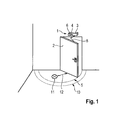
- the FIG. 1 shows a door 2, which is equipped with a door operator 1.
- the door 2 can only be moved within the movement area 5.
- the movement area 5 is shown only two-dimensionally for better explanation.
- the door operator 1 comprises a drive device 3, a sensor 4 and a control device 6.
- the drive device 3 is designed such that this can automatically close the door 2 again after a manual opening.
- the door operator 1 has a damping device with which a movement process of the door 2 can be damped.
- the sensor 4 is designed as a radar sensor that can monitor the detection area 10. Analogous to the movement region 5 of the door 2, the detection region 10 of the sensor 4 is also shown only in two dimensions. It is therefore easy to see that the detection area 10 of the sensor 4 is larger than the movement area 5 of the door 2, so that the movement area 5 can be reliably monitored for obstacles 11. Following the principle of this representation, however, the sensor 3 can also be used to monitor the actually three-dimensional movement space of the door 2.
- FIG. 12 shows a situation in which a user concealed by the door 2 opens the door 2.
- the sensor 4 detects the presence of the obstacle 11 in the movement area 5 of the door 2. If the obstacle 11 is detected, the control device 6 increases the damping of the drive device 3 such that the door will move more cumbersome. The user then feels a resistance when opening the door 2 and is thus warned in front of the obstacle 11.
- a distance 12 between the obstacle 11 and door 2 is determined by the control device 6. Depending on the distance 12, the control device 6 increases the damping of the drive device 3.
- the door 2 is becoming more difficult for the user to open, which is another sign of a threatening collision of the door with the obstruction 11 which is not visible to the user represents.
- the movement of the door 2 is stopped, for example, by the damping to a maximum value is set. In this case, it is no longer possible for the user to open the door 2 further. Thus, a collision between the obstacle 11 and door 2 is excluded.
- FIG. 2 shows a schematic view of the door operator 1 according to a second preferred embodiment of the invention.
- the door operator 1 in this embodiment comprises a drive device 3 and a damper device 7.
- the drive device 3 comprises a first part 31, a second part 32 and a third part 33.
- the first part 31 of the drive device 3 is a cam drive and serves to convert a rotation in a translation. Since the door 2 via a linkage 8 (see. FIG. 1 ) is connected to the first part 31, a rotation of the first part 31 causes a movement of the door 2. By the conversion function causes a rotation of the first part in addition to a translation of the second part 32.
- the second part 32 is designed as a piston which within a housing 17 of the door operator 1 is guided.
- the second part 32 is connected to a designed as an energy storage third part of the drive device 3 in conjunction.
- the third part 33 is designed in particular as a spring.
- the drive device 3 is designed in particular as a door closer, so that when opening the door 2 energy is stored, which is used to close the door 2. Therefore, opening the door 2 causes a rotation of the first part 31, which transmits this as a translation to the second part 32.
- the translation is transmitted from the second part 32 to the third part 33, which stores energy by elastic deformation. This energy can in turn be transmitted as a translation to the second part 32, which presses on the first part 31.
- the first part 31 generates from this a rotation with which the door 2 moves in the opposite direction, ie closed again.
- the door operator 1 also has a damping device 7.
- the damping device 7 comprises a line which connects a first chamber 18 of the housing 17 with a second chamber 19.
- the first chamber 18 and the second chamber 19 are formed by acting as a piston second part 32 of the drive device 3.
- Both chambers 18 and 19 are filled with a hydraulic fluid, so that upon movement of the piston, a flow 9 of the hydraulic fluid through the damping device 7 is formed. Therefore, movement of the door 2 can be damped by selecting the flow 9.
- the damping device 7 further comprises an adjusting device 13, via which the flow 9 can be changed.
- FIG. 3 shows a schematic view of the adjusting device 13.
- the adjusting device 13 comprises a cylindrical body having a first recess 15 and a second recess 16.
- a movement device 14 (cf. FIG. 2 ) can introduce either the first recess 15 or the second recess 16 of the adjusting device 13 in the oil flow 9. Since the first recess 15 is smaller than the second recess 16, the introduction of the first recess 15 causes a lower oil flow than the introduction of the second recess 16. Thus, with the adjusting device 13 of the oil flow 9 and thus the damping of the door movement to two different stages be set.
Landscapes
- Power-Operated Mechanisms For Wings (AREA)
Abstract
Description
- Die vorliegende Erfindung betrifft einen Türbetätiger, insbesondere einen Türschließer oder einen Türantrieb, zum Betätigen einer Türe.
- Unter Türbetätigern sind insbesondere Türschließer, Türantriebe oder Servotürschließer zu verstehen. Bei vorbekannten Türantrieben sind oftmals Sensoren vorhanden, die die Präsenz eines Hindernisses im Bewegungsbereich der angetriebenen Tür detektieren. Somit können Kollisionen zwischen Tür und Hindernis vermieden werden, indem das Öffnen oder Schließen der Tür rechtzeitig vor dem Hindernis gestoppt wird. Ebenso sind Systeme bekannt, die ein Öffnen der Türe lediglich unterstützen, die Tür aber nicht selbstständig betätigen. Mit solchen Betätigern wird beispielsweise ein Benutzer beim Öffnen oder Schließen von schweren Türen unterstützt, indem das Eigengewicht der Türe durch den Türantrieb kompensiert wird, Ein abruptes Stoppen der Türbewegung aufgrund eines Hindernisses ist hierbei jedoch unvorkeilhaft, da dadurch der Benutzter überrascht wird.
- Aus den zuvor genannten Gründen weist ein Türantrieb, der ausschließlich zum Unterstützen einer Bewegung einer Türe vorgesehen ist, keine Möglichkeiten auf, den Benutzer der Türe vor für ihn nicht sichtbaren Hindernissen auf der anderen Seite der Türe zu warnen. Das gleiche Problem tritt bei Türschließern auf. Da bekannte Türschließer den Öffnungsvorgang einer Türe nicht beeinflussen, können sie den Benutzer der Türe nicht vor für ihn unsichtbaren Hindernissen warnen.
- Es ist Aufgabe der vorliegenden Erfindung, einen Türbetätiger bereitzustellen, der bei einfacher und kostengünstiger Herstellung und Montage ein sicheres Betätigen einer Türe erlaubt.
- Die Aufgabe wird gelöst durch die Kombination der Merkmale des Anspruchs 1, Demnach wird die Aufgabe durch einen Türbetätiger gelöst, der eine Antriebsvorrichtung umfasst, die eine öffnung- und/oder Schließkraft auf eine Türe aufbringen kann. Weiterhin umfasst der erfindungsgemäße Türbetätiger mindestens einen Sensor, der einen Bewegungsbereich der Türe überwacht. Bevorzugt überwacht der Sensor den Bewegungsbereich der Türe, der für einen Benutzer beim Betätigen der Türe nicht einsehbar ist. Außerdem weist der Türbetätiger eine Steuervorrichtung auf, die sowohl mit dem Sensor als auch mit der Antriebsvorrichtung verbunden ist. Daher kann die Steuervorrichtung die Antriebsvorrichtung ansteuern, was bevorzugt in Abhängigkeit eines Signals des Sensors geschieht. Dabei ist die Antriebsvorrichtung bevorzugt eingerichtet, einen manuellen Öffnungsvorgang der Türe durch einen Benutzer zu unterstützen. Ebenso bevorzugt kann die Antriebsvorrichtung die Türe auch selbstständig betätigen, Es ist ersichtlich, dass die Steuervorrichtung mehrere Funktionen erfüllen kann. Erfindungsgemäß ist jedoch vorgesehen, dass die Steuervorrichtung zumindest derart eingerichtet ist, die Beweglichkeit der Türe zu erschweren. Das bedeutet, dass die Antriebsvorrichtung derart angesteuert wird, dass ein Benutzer beim Betätigen der Türe eine im Vergleich zum normalen Betätigen erhöhte Kraft aufwenden muss.
- Die Unteransprüche zeigen bevorzugte Weiterbildungen der Erfindung.
- In einer bevorzugten Ausführungsform der Erfindung wird der Sensor zum Detektieren von Hindernissen im Bewegungsbereich der Türe verwendet. Der Sensor erkennt beispielsweise Personen oder Gegenstände, die sich in einem für einen Benutzer der Tür nicht sichtbaren Bewegungsbereich der Türe aufhalten oder dort abgestellt sind. Sollte die Steuervorrichtung erkennen, dass der Sensor ein Hindernis detektiert hat, steuert diese bevorzugt die Antriebsvorrichtung derart an, dass das Bewegen der Türe für einen Benutzer erschwert wird. Auf diese Weise wird der Benutzer intuitiv vor dem Hindernis gewarnt und zum vorsichtigen und gefahrlosen Betätigen der Türe angeleitet. Zusätzlich bietet diese Variante im Gegensatz zu einem abrupten Stoppen der Tür vor einem Hindernis den Vorteil, dass der Benutzer beim Bedienen der Tür nicht überrascht wird.
- In einer vorteilhaften Ausführungsform der Erfindung weist die Antriebsvorrichtung einen Aktor auf. Bei diesem Aktor kann es sich insbesondere um einen Motor handeln. Der Aktor kann verwendet werden, um die Tür aktiv zu bewegen. Bevorzugt wird der Aktor dazu verwendet, das Eigengewicht der Türe zu kompensieren, um dem Benutzer ein Bewegen der Türe zu erleichtern. Andererseits kann der Aktor vorteilhafterweise eine Gegenkraft auf die Tür aufbringen, um einen Bewegungsvorgang zu erschweren, wenn dies von der Steuervorrichtung angefordert wird.
- Weiterhin ist bevorzugt vorgesehen, dass der Türbetätiger eine Dämpfungsvorrichtung aufweist. Über die Dämpfungsvorrichtung kann eine Bewegung der Tür gedämpft werden, wobei der Grad der Dämpfung von der Steuervorrichtung einstellbar ist. Mit der Dämpfungsvorrichtung kann sowohl eine durch die Antriebsvorrichtung als auch eine durch den Benutzer initiierte Bewegung der Türe gedämpft werden. Beispielsweise kann die Dämpfungsvorrichtung einen selbsttätigen Schließvorgang der Türe dämpfen. Ebenso kann die Steuervorrichtung bei erkanntem Hindernis die Dämpfung während eines Bewegens der Tür durch den Benutzer verändern. Falls die Dämpfung erhöht wird, wird auch das Bewegen der Türe erschwert, wodurch der Benutzer vor dem erkannten Hindernis gewarnt wird,
- Besonders bevorzugt ist die Dämpfungsvorrichtung hydraulisch ausgebildet. Der Grad der Dämpfung wird dabei über dem Fluss eines Hydraulikfluids eingestellt, wozu die Dämpfungsvorrichtung eine Stellvorrichtung aufweist. Dieser einfache Aufbau ermöglicht es daher, das erfindungsgemäße Erschweren einer Türbewegung durch Ansteuern der Stellvorrichtung auszuführen. Als Hydraulikfluid kann beispielsweise ein aus dem Stand der Technik bekanntes Öl verwendet werden,
- Der Sensor zum Überwachen des Bewegungsbereichs der Türe ist bevorzugt ein Tiefensensor. Dabei kann der Tiefensensor aktiv oder passiv arbeiten. Beispielsweise können Radarsensoren oder Kamerasysteme verwendet werden, deren Erfassungsbereich sich auf den Bewegungsbereich der Türe erstreckt. Die Verwendung von Tiefensensoren ermöglicht ein einfaches und zuverlässiges Erkennen von Personen oder Gegenständen im Bewegungsbereich der Türe. Ebenso wird ermöglicht, den Abstand der Hindernisse zu der Türe zu bestimmen, so dass beispielsweise die Bewegung der Türe immer weiter erschwert wird, je näher sie an das Hindernis herankommt.
- Die Erfindung betrifft außerdem ein Verfahren zum Beeinflussen einer durch einen Benutzer erzeugten Bewegung einer Türe. Zum Durchführen dieses Verfahrens wird zunächst der Bewegungsbereich einer Türe mit mindestens einem Sensor überwacht. Sollte der Sensor ein Hindernis detektiert haben, so wird auf die Türe eine Kraft aufgebracht, wodurch sie für den Benutzer schwergängiger zu bewegen wird. Das Aufbringen der Kraft erfolgt über einen Türbetätiger, der in die Türbewegung des Benutzers eingreifen kann. Bevorzugt greift der Türbetätiger nicht in den Bewegungsvorgang der Türe ein, wenn kein Hindernis vom Sensor detektiert wurde.
- Das Verfahren wird bevorzugt durchgeführt, indem der Türbetätiger aktiv eine Kraft erzeugt, die auf die Türe wirkt. Die Größe dieser Kraft kann bevorzugt eingestellt werden, so dass die Schwergängigkeit der Tür variabel ist. Ebenso bevorzugt wird das Verfahren ausgeführt, indem der Türbetätiger die Bewegung der Türe dämpft. Das Dämpfen kann dabei sowohl während einer Bewegung der Türe durch den Türbetätiger als auch während der Bewegung der Türe durch den Benutzer geschehen. Bevorzugt kann der Grad der Dämpfung eingestellt werden.
- Falls der Sensor kein Hindernis im Bewegungsbereich der Tür detektiert, ist es vorteilhaft, dass die Bewegung der Türe durch den Benutzer vom Türbetätiger unterstützt wird. Dies kann beispielsweise dadurch geschehen, dass das Eigengewicht der Türe kompensiert wird, so dass der Benutzter lediglich die Türe führen, nicht jedoch deren Gewicht bewegen muss, Ebenso kann dem Benutzer Arbeit abgenommen werden, indem die Tür selbstständig bewegt wird. Beispielsweise kann die Tür nach einem Öffnen durch einen Benutzer wieder selbstständig geschlossen werden.
- In einer vorteilhaften Ausführungsform bestimmt der Sensor nicht nur das Vorhandensein eines Hindernisses, sondern auch den Abstand des Hindernisses zu der Tür. Zusätzlich wird der Abstand zwischen Tür und Hindernis mit dem Bewegen der Türe laufend aktualisiert. Dies ermöglicht es, die vom Türbetätiger auf die Türe aufgebrachte Kraft in Abhängigkeit von der Entfernung zwischen Tür und Hindernis zu verändern. Beispielsweise steigt die Schwergängigkeit der Türe mit sinkender Entfernung zum Hindernis an. Damit wird der Benutzer deutlich und nachhaltig vor dem Vorhandensein des Hindernisses gewarnt. Jedoch wird er durch den kontinuierlichen Anstieg der zum Bewegen der Tür notwendigen Kraft nicht überrascht.
- Bevorzugt ist vorgesehen, dass die Türe nicht mit dem Hindernis kollidiert. Dazu wird die Bewegung der Türe gestoppt, bevor diese das Hindernis erreicht. Auf diese Weise wird sichergestellt, dass Tür und Hindernis unversehrt bleiben. Dies ist insbesondere dann von Vorteil, wenn es sich bei dem Hindernis um einen Menschen handelt. Daher wird durch das Stoppen der Türe auch die Betriebssicherheit des Türbetätigers erhöht.
- Die Erfindung wird nun anhand bevorzugter Ausführungsbeispiele unter Berücksichtigung der beigefügten Zeichnungen näher beschrieben, Dabei zeigen:
- Figur 1
- eine Türe, die mit einem Türbetätiger gemäß eines ersten bevorzugten Ausführungsbeispiels der Erfindung ausgestattet ist,
- Figur 2
- eine schematische Ansicht eines Türbetätigers gemäß eines zweiten bevorzugten Ausführungsbeispiels der Erfindung, und
- Figur 3
- eine schematische Ansicht der Einstellvorrichtung der Dämpfungsvorrichtung des Türbetätigers gemäß des zweiten bevorzugten Ausführungsbeispiels der Erfindung.
- Die
Figur 1 zeigt eine Türe 2, die mit einem Türbetätiger 1 ausgestattet ist. Zum Öffnen und Schließen kann die Tür 2 nur innerhalb des Bewegungsbereich 5 bewegt werden. In dieser Darstellung ist der Bewegungsbereich 5 zur besseren Erläuterung lediglich zweidimensional dargestellt. Der Türbetätiger 1 umfasst eine Antriebsvorrichtung 3, einem Sensor 4 und einer Steuervorrichtung 6. Die Antriebsvorrichtung 3 ist derart ausgelegt, dass diese die Tür 2 nach einem manuellen Öffnen wieder automatisch schließen kann. Weiterhin weist der Türbetätiger 1 eine Dämpfungsvorrichtung auf, mit der ein Bewegungsvorgang der Türe 2 gedämpft werden kann. - Der Sensor 4 ist als Radarsensor ausgeführt, der den Erfassungsbereich 10 überwachen kann. Analog zum Bewegungsbereich 5 der Türe 2 ist auch der Erfassungsbereich 10 des Sensors 4 nur zweidimensional eingezeichnet. Es ist daher einfach ersichtlich, dass der Erfassungsbereich 10 des Sensors 4 größer als der Bewegungsbereich 5 der Türe 2 ist, so dass der Bewegungsbereich 5 zuverlässig auf Hindernisse 11 überwacht werden kann. Dem Prinzip dieser Darstellung folgend kann mit dem Sensor 4 jedoch auch der eigentlich dreidimensionale Bewegungsraum der Türe 2 überwacht werden.
-
Figur 1 zeigt eine Situation, in der ein durch die Tür 2 verdeckter Benutzer die Tür 2 öffnet. Daher ist für ihn nicht ersichtlich, ob sich auf der ihm abgewandten Seite der Türe 2 ein Hindernis 11 befindet oder nicht. Daher detektiert der Sensor 4 das Vorhandensein des Hindernisses 11 im Bewegungsbereich 5 der Türe 2. Ist das Hindernis 11 erkannt, so vergrößert die Steuervorrichtung 6 die Dämpfung der Antriebsvorrichtung 3 derart, dass die Tür schwerfälliger zu bewegen wird. Der Benutzer spürt daraufhin einen Widerstand beim Öffnen der Türe 2 und ist somit vor dem Hindernis 11 gewarnt. Zusätzlich wird von der Steuerungsvorrichtung 6 ein Abstand 12 zwischen Hindernis 11 und Türe 2 bestimmt. In Abhängigkeit von dem Abstand 12 erhöht die Steuerungsvorrichtung 6 die Dämpfung der Antriebsvorrichtung 3. Somit wird die Tür 2 für den Benutzer immer schwerer zu öffnen, was für den Benutzer ein weiteres Zeichen für eine drohende Kollision der Türe mit dem für ihn nicht einsehbaren Hindernis 11 darstellt. Bei Unterschreiten eines festgelegten Abstandes 12 wird die Bewegung der Türe 2 gestoppt, z.B., indem die Dämpfung auf einen maximalen Wert gesetzt wird. In diesem Fall ist es dem Benutzer nicht mehr möglich, die Türe 2 weiter zu öffnen. Somit ist eine Kollision zwischen Hindernis 11 und Türe 2 ausgeschlossen. -
Figur 2 zeigt eine schematische Ansicht des Türbetätigers 1 gemäß eines zweiten bevorzugten Ausführungsbeispiels der Erfindung. Dabei wurden gleiche bzw. funktional gleiche Elemente mit den gleichen Bezugszeichen versehen. Der Türbetätiger 1 umfasst in diesem Ausführungsbeispiel eine Antriebsvorrichtung 3 und eine Dämpfungsvorrichtung 7. Die Antriebsvorrichtung 3 umfasst ein erstes Teil 31, ein zweites Teil 32 und ein drittes Teil 33. Das erste Teil 31 der Antriebsvorrichtung 3 ist ein Nockenantrieb und dient zum Wandeln einer Rotation in eine Translation. Da die Türe 2 über ein Gestänge 8 (vgl.Figur 1 ) mit dem ersten Teil 31 verbunden ist, bewirkt eine Rotation des ersten Teils 31 eine Bewegung der Türe 2. Durch die Wandlungsfunktion bewirkt eine Rotation des ersten Teils außerdern eine Translation des zweiten Teils 32. Das zweite Teil 32 ist als Kolben ausgeführt, der innerhalb eines Gehäuses 17 des Türbetätigers 1 geführt ist. Das zweite Teil 32 steht mit einem als Energiespeicher ausgeführten dritten Teil der Antriebsvorrichtung 3 in Verbindung. Das dritte Teil 33 ist dabei insbesondere als Feder ausgeführt. - Die Antriebsvorrichtung 3 ist insbesondere als Türschließer ausgebildet, so dass beim Öffnen der Türe 2 Energie gespeichert wird, die zum Schließen der Türe 2 verwendet wird. Daher bewirkt ein Öffnen der Türe 2 eine Rotation des ersten Teils 31, welche dieses als Translation an das zweite Teil 32 weitergibt. Die Translation wird vom zweiten Teil 32 auf das dritte Teil 33 übertragen, das durch elastische Verformung Energie speichert, Diese Energie kann wiederum als Translation auf das zweite Teil 32 übertragen werden, welches auf das erste Teil 31 drückt. Das erste Teil 31 erzeugt daraus eine Rotation, mit der die Türe 2 in die entgegengesetzte Richtung bewegt, d.h. wieder geschlossen, wird.
- Der Türbetätiger 1 weist außerdem eine Dämpfungsvorrichtung 7 auf. Die Dämpfungsvorrichtung 7 umfasst eine Leitung, die eine erste Kammer 18 des Gehäuses 17 mit einer zweiten Kammer 19 verbindet. Die erste Kammer 18 und die zweite Kammer 19 werden durch das als Kolben fungierende zweite Teil 32 der Antriebsvorrichtung 3 gebildet. Beide Kammern 18 und 19 sind mit einem Hydraulikfluid gefüllt, so dass bei einer Bewegung des Kolbens ein Fluss 9 des Hydraulikfluids durch die Dämpfungsvorrichtung 7 entsteht. Daher kann eine Bewegung der Türe 2 durch Wahl des Flusses 9 gedämpft werden. Die Dämpfungsvorrichtung 7 weist weiterhin eine Stellvorrichtung 13 auf, über die der Fluss 9 geändert werden kann.
-
Figur 3 zeigt eine schematische Ansicht der Stellvorrichtung 13. Die Stellvorrichtung 13 umfasst einem zylinderförmigen Körper, der eine erste Ausnehmung 15 und eine zweite Ausnehmung 16 aufweist. Eine Bewegungsvorrichtung 14 (vgl.Figur 2 ) kann entweder die erste Ausnehmung 15 oder die zweite Ausnehmung 16 der Stellvorrichtung 13 in den Ölfluss 9 einbringen. Da die erste Ausnehmung 15 kleiner ist als die zweite Ausnehmung 16, bewirkt das Einbringen der ersten Ausnehmung 15 einen geringeren Ölfluss als das Einbringen der zweiten Ausnehmung 16. Damit kann mit der Stellvorrichtung 13 der Ölfluss 9 und damit die Dämpfung der Türbewegung auf zwei unterschiedliche Stufen eingestellt werden.Bezugszeichenliste 1 Türbetätiger 2 Türe 3 Antriebsvorrichtung 31 erstes Teil der Antriebsvorrichtung 32 zweites Teil der Antriebsvorrichtung 33 drittes Teil der Antriebsvorrichtung 4 Sensor 5 Bewegungsraum der Türe 6 Steuervorrichtung 7 Dämpfungsvorrichtung 8 Gestänge 9 Fluss des Hydraulikfluids 10 Erfassungsbereich des Sensors 11 Hindernis 12 Abstand zwischen Hindernis und Türe 13 Stellvorrichtung 14 Bewegungsvorrichtung 15 erste Ausnehmung 16 zweite Ausnehmung 17 Gehäuse 18 erste Kammer des Gehäuses 19 zweite Kammer des Gehäuses
Claims (12)
- Türbetätiger (1) für eine Türe (2), umfassend- eine Antriebsvorrichtung (3) für die Türe (2),- mindestens einen Sensor (4), der zumindest den Bewegungsbereich (5) der Türe (2) überwacht, und- eine Steuervorrichtung (6), die mit dem Sensor (4) und der Antriebsvorrichtung (3) verbunden ist,- wobei die Steuervorrichtung (6) zumindest eingerichtet ist, die Antriebsvorrichtung (3) derart anzusteuern, dass ein Bewegen der Türe (2) erschwert ist.
- Türbetätiger nach Anspruch 1, wobei die Steuervorrichtung (6) weiter eingerichtet ist, das Bewegen der Türe (2) zu erschweren, wenn der Sensor (4) ein Hindernis im Bewegungsbereich (5) detektiert.
- Türbetätiger nach einem der vorhergehenden Ansprüche, wobei die Antriebsvorrichtung (3) einen Aktor, insbesondere einen Motor, umfasst.
- Türbetätiger nach einem der vorhergehenden Ansprüche, umfassend eine Dämpfungsvorrichtung (7), welche die Bewegung der Türe (2) dämpft, wobei der Grad der Dämpfung der Dämpfungsvorrichtung (7) von der Steuervorrichtung (6) einstellbar ist.
- Türbetätiger nach Anspruch 4, wobei- die Dämpfungsvorrichtung (7) hydraulisch ausgebildet ist und ein Hydraulikfluid und eine Stellvorrichtung (13) aufweist, und- über die Stellvorrichtung (13) der Fluss (9) des Hydraulikfluids einstellbar ist.
- Türbetätiger nach einem der vorhergehenden Ansprüche, wobei der Sensor (4) ein aktiver oder ein passiver Tiefensensor ist.
- Verfahren zum Beeinflussen einer durch einen Benutzer erzeugte Bewegung einer Tür (2), umfassend die Schritte:- Detektieren eines Hindernisses in einem Bewegungsbereich (6) der Türe mittels mindestens eines Sensors (4), und- Aufbringen einer Kraft auf die Türe durch einen Türbetätiger (1), so dass die Türe (2) für den Benutzer schwergängiger zu bewegen wird.
- Verfahren nach Anspruch 7, wobei durch den Türbetätiger (1) aktiv eine Kraft erzeugt wird.
- Verfahren nach einem der Ansprüche 7 oder 8, wobei der Türbetätiger (1) die Bewegung der Türe (2) dämpft.
- Verfahren nach einem der Ansprüche 7 bis 9, wobei die vom Benutzer erzeugte Bewegung der Tür (2) von dem Türbetätiger (1) unterstützt wird, wenn kein Hindernis im Bewegungsbereich (5) der Türe (2) detektiert wird.
- Verfahren nach einem der Ansprüche 7 bis 10, wobei die von dem Türbetätiger (1) auf die Tür (2) aufgebrachte Kraft abhängig von der Entfernung der Tür (2) zu dem detektieren Hindernis ist.
- Verfahren nach einem der Ansprüche 7 bis 11, wobei die Bewegung der Türe (2) gestoppt wird, bevor die Türe (2) mit dem detektierten Hindernis kollidiert.
Applications Claiming Priority (1)
| Application Number | Priority Date | Filing Date | Title |
|---|---|---|---|
| DE102012103337A DE102012103337A1 (de) | 2012-04-17 | 2012-04-17 | Türbetätiger mit haptischem Feedback |
Publications (1)
| Publication Number | Publication Date |
|---|---|
| EP2653643A1 true EP2653643A1 (de) | 2013-10-23 |
Family
ID=48082815
Family Applications (1)
| Application Number | Title | Priority Date | Filing Date |
|---|---|---|---|
| EP13001629.8A Withdrawn EP2653643A1 (de) | 2012-04-17 | 2013-03-28 | Türbetätiger mit haptischem Feedback |
Country Status (2)
| Country | Link |
|---|---|
| EP (1) | EP2653643A1 (de) |
| DE (1) | DE102012103337A1 (de) |
Cited By (1)
| Publication number | Priority date | Publication date | Assignee | Title |
|---|---|---|---|---|
| DE102016113696A1 (de) * | 2016-07-25 | 2018-01-25 | Witte Automotive Gmbh | Vorrichtung zur Beeinflussung der Beweglichkeit einer Tür |
Citations (1)
| Publication number | Priority date | Publication date | Assignee | Title |
|---|---|---|---|---|
| US20090260289A1 (en) * | 2008-04-18 | 2009-10-22 | Michael Carpenter | Door Safety System |
-
2012
- 2012-04-17 DE DE102012103337A patent/DE102012103337A1/de not_active Withdrawn
-
2013
- 2013-03-28 EP EP13001629.8A patent/EP2653643A1/de not_active Withdrawn
Patent Citations (1)
| Publication number | Priority date | Publication date | Assignee | Title |
|---|---|---|---|---|
| US20090260289A1 (en) * | 2008-04-18 | 2009-10-22 | Michael Carpenter | Door Safety System |
Cited By (1)
| Publication number | Priority date | Publication date | Assignee | Title |
|---|---|---|---|---|
| DE102016113696A1 (de) * | 2016-07-25 | 2018-01-25 | Witte Automotive Gmbh | Vorrichtung zur Beeinflussung der Beweglichkeit einer Tür |
Also Published As
| Publication number | Publication date |
|---|---|
| DE102012103337A1 (de) | 2013-10-17 |
Similar Documents
| Publication | Publication Date | Title |
|---|---|---|
| EP3325748B1 (de) | Türkomponente mit einer steuerbaren dämpfereinrichtung | |
| EP3299561B1 (de) | Stellvorrichtung | |
| EP0710316B1 (de) | Verfahren zum betrieb eines drehtürantriebes | |
| EP3272987B1 (de) | Vorrichtung zum fremdkraftbetätigten und manuellen verstellen eines fahrzeugteils | |
| DE102004061687A1 (de) | Fahrzeugtür mit einer Abbremsfunktion | |
| EP3103949A1 (de) | Türantrieb | |
| DE102010021576A1 (de) | Vorrichtung für eine Stellklappe eines Tragflügels | |
| DE102004061686A1 (de) | Fahrzeugtür mit variabler Rastfunktion | |
| DE102014224123A1 (de) | Verfahren zum Betreiben eines robotischen Gerätes und robotisches Gerät | |
| DE102011108649B4 (de) | Drehmomentübertragungseinheit | |
| DE102014225150A1 (de) | Verschwenken eines verschwenkbaren Karosserieteils eines Kraftfahrzeugs mittels eines fremdkraftbetriebenen Antriebs in einem Automatik-Betrieb oder in einem Servo-Betrieb | |
| EP0561361B1 (de) | Verfahren zum Steuern von Torantrieben und Vorrichtung hierfür | |
| DE10348917B4 (de) | Türstoppsystem mit Hinderniserkennung | |
| WO2022167043A1 (de) | Verfahren zur motorischen bewegungsunterstützung einer fahrzeugtür | |
| DE102015111568A1 (de) | Öffnungsvorrichtung für eine Kraftfahrzeugtür | |
| EP2653643A1 (de) | Türbetätiger mit haptischem Feedback | |
| DE19700828C5 (de) | Verfahren zum Betrieb einer automatischen Türanlage | |
| DE102014118567B4 (de) | Verfahren zur Kompensation eines Stick-Slip-Effektes bei einer Kugelumlauflenkung | |
| AT525030A1 (de) | Möbelantriebssystem für ein bewegbares Möbelteil | |
| EP3468753B1 (de) | Verfahren zum sicheren stillsetzen eines manipulators | |
| DE102016114376A1 (de) | Feedback-unterstützte Fernsteuerung für Fahrzeugtüren | |
| EP3078477B1 (de) | Verfahren und blasformanlage zur extrusion von vorformlingen, die durch blasformen zu kunststoffhohlkörpern aufgeweitet werden | |
| EP0879969A2 (de) | Verfahren zum Steuern eines fluidischen Antriebes | |
| DE102015000531B4 (de) | Verfahren zum Betreiben einer Türeinrastvorrichtung und Türeinrastvorrichtung | |
| DE102015004692A1 (de) | Verfahren zum Betrieb eines Roboters und Vorrichtung zur Durchführung des Verfahrens |
Legal Events
| Date | Code | Title | Description |
|---|---|---|---|
| PUAI | Public reference made under article 153(3) epc to a published international application that has entered the european phase |
Free format text: ORIGINAL CODE: 0009012 |
|
| AK | Designated contracting states |
Kind code of ref document: A1 Designated state(s): AL AT BE BG CH CY CZ DE DK EE ES FI FR GB GR HR HU IE IS IT LI LT LU LV MC MK MT NL NO PL PT RO RS SE SI SK SM TR |
|
| AX | Request for extension of the european patent |
Extension state: BA ME |
|
| 17P | Request for examination filed |
Effective date: 20140423 |
|
| RBV | Designated contracting states (corrected) |
Designated state(s): AL AT BE BG CH CY CZ DE DK EE ES FI FR GB GR HR HU IE IS IT LI LT LU LV MC MK MT NL NO PL PT RO RS SE SI SK SM TR |
|
| RAP1 | Party data changed (applicant data changed or rights of an application transferred) |
Owner name: DORMA DEUTSCHLAND GMBH |
|
| 17Q | First examination report despatched |
Effective date: 20160217 |
|
| STAA | Information on the status of an ep patent application or granted ep patent |
Free format text: STATUS: THE APPLICATION IS DEEMED TO BE WITHDRAWN |
|
| 18D | Application deemed to be withdrawn |
Effective date: 20160628 |