EP2653616A2 - Structural element for three-dimensional structures in the garden - Google Patents
Structural element for three-dimensional structures in the garden Download PDFInfo
- Publication number
- EP2653616A2 EP2653616A2 EP13164726.5A EP13164726A EP2653616A2 EP 2653616 A2 EP2653616 A2 EP 2653616A2 EP 13164726 A EP13164726 A EP 13164726A EP 2653616 A2 EP2653616 A2 EP 2653616A2
- Authority
- EP
- European Patent Office
- Prior art keywords
- structural element
- positioning
- front side
- recesses
- structural
- Prior art date
- Legal status (The legal status is an assumption and is not a legal conclusion. Google has not performed a legal analysis and makes no representation as to the accuracy of the status listed.)
- Withdrawn
Links
Images


Classifications
-
- E—FIXED CONSTRUCTIONS
- E02—HYDRAULIC ENGINEERING; FOUNDATIONS; SOIL SHIFTING
- E02D—FOUNDATIONS; EXCAVATIONS; EMBANKMENTS; UNDERGROUND OR UNDERWATER STRUCTURES
- E02D17/00—Excavations; Bordering of excavations; Making embankments
- E02D17/20—Securing of slopes or inclines
-
- E—FIXED CONSTRUCTIONS
- E04—BUILDING
- E04F—FINISHING WORK ON BUILDINGS, e.g. STAIRS, FLOORS
- E04F13/00—Coverings or linings, e.g. for walls or ceilings
- E04F13/07—Coverings or linings, e.g. for walls or ceilings composed of covering or lining elements; Sub-structures therefor; Fastening means therefor
- E04F13/08—Coverings or linings, e.g. for walls or ceilings composed of covering or lining elements; Sub-structures therefor; Fastening means therefor composed of a plurality of similar covering or lining elements
- E04F13/0862—Coverings or linings, e.g. for walls or ceilings composed of covering or lining elements; Sub-structures therefor; Fastening means therefor composed of a plurality of similar covering or lining elements composed of a number of elements which are identical or not, e.g. carried by a common web, support plate or grid
-
- E—FIXED CONSTRUCTIONS
- E04—BUILDING
- E04F—FINISHING WORK ON BUILDINGS, e.g. STAIRS, FLOORS
- E04F13/00—Coverings or linings, e.g. for walls or ceilings
- E04F13/07—Coverings or linings, e.g. for walls or ceilings composed of covering or lining elements; Sub-structures therefor; Fastening means therefor
- E04F13/08—Coverings or linings, e.g. for walls or ceilings composed of covering or lining elements; Sub-structures therefor; Fastening means therefor composed of a plurality of similar covering or lining elements
- E04F13/10—Coverings or linings, e.g. for walls or ceilings composed of covering or lining elements; Sub-structures therefor; Fastening means therefor composed of a plurality of similar covering or lining elements of wood or with an outer layer of wood
Definitions
- the present invention relates to a structural element which allows the uncomplicated cladding with decorative slats and can be used for the production of space-forming structures.
- the object of the invention is to avoid the disadvantages mentioned and to provide structural elements with which space-forming structures in the garden area, in particular raised beds, can be realized and which structural elements at the same time allow uncomplicated dressing with wooden slats.
- the wooden slats should be oriented to each other in a defined manner, preferably to form a grid-like structure.
- the structural elements have positioning elements with recesses, wherein the positioning elements are arranged on edges of the front sides. It is irrelevant whether the edge in the case of a designed as a polygon front consists of straight edges or in the case of a round, such as a circular or elliptical front of curved lines.
- the respective positioning element is from the front and is preferably designed as a bar.
- the respective positioning element can in particular enclose a right angle with the plane of the front side.
- the recesses are dimensioned so that in each case a wooden slat can be positioned.
- a wooden slat By positioning a wooden slat in two recesses of different positioning strips, the position of the wooden slat in the room is determined.
- a plurality of recesses per positioning element or positioning strip By arranging a plurality of recesses per positioning element or positioning strip, a variety of wooden slats can be positioned.
- a structural element according to the invention that this comprises a plate-shaped base body with a front and a back, wherein the front is bounded by an edge along which at least partially at least one positioning strip is arranged, which protrudes from the plane of the front, wherein the positioning strip has at least one recess for receiving and spatial alignment of a trim strip, preferably made of wood.
- the front side is formed as a polygon, i. the edge consists of edges.
- At least one edge of a positioning strip is arranged with a plurality of recesses.
- the recesses are arranged in a jagged manner on a side edge of the positioning strip which is preferably arranged parallel to the front side. "Jagged" means that recesses are not completely edged, but are open to one side, so that a wooden batten can be easily inserted into the recess.
- the resulting structure of the corresponding side edge of the positioning bar can also be referred to as comb-like.
- the edge of the front side is formed by edges and that along at least one of these edges a positioning strip is arranged with a plurality of recesses, wherein the recesses along a side edge of the respective positioning strip are arranged like a jag.
- the recesses not jagged, but run as completely edged holes.
- the wooden slats must be guided with one end in the direction of their longitudinal extent through the recesses in order to be positioned.
- a possible fixation of the wooden slats then serves only to prevent movement of the respective wooden slat in the direction of its longitudinal extent.
- the base body has a plurality of holes. These holes serve that a mounting bar, which is preferably made of wood, can be screwed to the base body. This is done before positioning the decorative slats or wooden slats. After the wooden slats are fixed in the recesses, the wooden slats can now be easily connected to the mounting bar, preferably by means of nails or screws or Chipboard screws. In the case of a polygonal front, which is bordered by edges, it is advisable to arrange the holes parallel to the course of those edges on which positioning strips are arranged.
- the structural elements can be connected directly to one another by screwing together two adjoining positioning strips of different structural elements.
- the at least one positioning strip has a plurality of bores.
- the bores are preferably arranged along a straight line which extends in each case parallel to that edge of the polygonal front side on which the respective positioning strip is arranged.
- walls can be made of structural elements that extend along one direction.
- preferably corresponding angle connecting elements are provided, with which in each case two positioning strips of different structural elements or walls are screwed.
- raised beds with rectangular -aber in the case of non-rectangular angle connecting elements with non-rectangular polygonal - outline easily.
- angle it is also possible with angle to be connected structural elements to dispense with the angle connecting elements by connecting the positioning strips in a corresponding (obtuse) angles are bent away from the front sides and bolted directly together.
- the structural element In order to enable a visually appealing conclusion of the structural elements or walls, it is provided in a particularly preferred embodiment of the structural element according to the invention that along the edge of the front side sections at least one boundary strip is arranged, which protrudes from the plane of the front and preferably has a plurality of holes , Preferably, the at least one boundary strip encloses a right angle with the plane of the front side.
- the holes in the bordering bar allow you to attach a finishing batten to the bordering strip.
- these end slats serve not only an optical purpose, but also as a handrail or allow the user comfortable support at the top of the raised bed.
- the final lath also fulfills a protective function, by avoiding injury to the user at the bordering strip, which may consist in particular of sheet metal.
- the structural element is made of metal.
- the entire structural element in unwound form can first be punched from a metal plate, including all the recesses and holes.
- the protruding from the front positioning strips and boundary strips are completed in the sequence by simply upending. Accordingly, it is in a particularly preferred embodiment of the invention Structural element provided that the structural element is made in one piece.
- the use of several structural elements according to the invention for producing a space-building structure such as a raised bed, a sandbox or garden shed, provided, wherein in the recesses at least one decorative plate is arranged and the structural elements preferably by means of screwed together and / or with angle connecting elements and / or connected to at least one door frame element.
- the structural elements according to the invention for the realization of space-forming structures, but to use for cladding a facade.
- the structural elements for example, together with mounting bars can be screwed to a facade of a house or a wall and then provided with wooden slats.
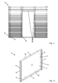
- an inventive structural element 1 which comprises a base body 2, which in turn has a rectangular front side 3 and a back side 4 (cf. Fig. 4 ) having.
- the front side 3 has a width 16 and a height 17, cf. Fig. 3 , wherein in the illustrated embodiment, the width 16 greater than the height 17 fails.
- the width 16 is typically 900 mm to 1000 mm and the height 17 is typically 750 mm.
- the height 17 may also have other values for raised beds 13, in particular it is adaptable to the size of the user and is usually in a range between 450 mm (for children) and 800 mm (for adults).
- the height 17 drops correspondingly lower and is usually in the range of 250 mm to 300 mm.
- the height 17 correspondingly larger and is in a range between 2000 mm and 2400 mm, typically 2200 mm.
- the front 3 has an edge 5, which is formed by four edges. On two opposite edges positioning strips 6 are arranged, which form a right angle with the plane of the front 3.
- Fig. 2 shows a plan view of a positioning strip 6, in which it can be clearly seen that the positioning strip 6 has a side edge 9, which is seen from the front side 3 in the direction normal to the plane of the front side 3 spaced. That is, the side edge 9 has the front side 3 at a normal distance greater than zero. The corresponding maximum normal distance from points on the side edge 9 to the front side 3 is equal to a width 18 of the positioning bar 6. A typical value for the width 18 would be 47 mm.
- the positioning strip 6 is provided with recesses 7, which are arranged along the side edge 9 so that a serrated or comb-like structure of the side edge 9 is given.
- the recesses 7 are used to position wooden slats 8 by each wooden slat 8 is placed or placed both in a recess 7 of a positioning bar 6 and in a recess 7 of the other positioning bar 6.
- Fig. 12 shows an alternative embodiment of the structural element 1 according to the invention, which is characterized by recesses 7, which are designed as completely edged recesses 7 and holes in the positioning strips 6.
- the wooden battens 8 must be guided with one end in the direction of their longitudinal extent through the recesses 7 in order to be positioned.
- a possible fixation of the wooden slats 8 then serves only to prevent movement of the respective wooden slat 8 in the direction of its longitudinal extent.
- mounting beams 12 made of wood with fastening means 21, such as nails or chipboard screws.
- fastening means 21 such as nails or chipboard screws.
- the mounting bars 12 are fixed to the front side 3 by means of screws 20.
- the base body 2 bores 11, which are arranged along a straight line on the front side 3, parallel to the positioning strips 6.
- the structural element 1 also has two boundary strips 10, which are each arranged along the edges, along which no positioning strips 6 are arranged. Accordingly, the positioning strips 6 and the boundary strips 10 at right angles to each other.
- the boundary strips 10 are also bent as well as the positioning strips 6 at a right angle out of the plane of the front side 3, ie the boundary strips 10 close with the plane of the front 3 also a right angle.
- the boundary strips 10 have holes 11, which facilitate the simple installation of a cover strip 22 by means of screws 20 enable. But it must not be mounted on both boundary strips 10 such end strips 22.
- the bores 11 of the boundary strip 10 can also be used for fixing the structural element 1 on a frame (not shown) or for connecting two structural elements 1 arranged one above the other, which abut one another with a respective boundary strip 10 (not shown).
- the boundary strips 10 have a width 19, which in Fig. 4 is clearly visible and the same size as the width 18 of the positioning strips 6 fails.
- the mounted on the bordering bar 10 graduation batten 22 can of course have larger dimensions and project beyond the boundary strip 10. This is in the side view of Fig. 7 Particularly well recognizable, where the final lath 10 projects beyond not only the boundary strip 10 but also the wooden slats 8.
- Fig. 8 shows for better illustration also an axonometric view of the wood slats 8 clad structural element. 1
- the structural element 1 is made of metal and in one piece.
- the complete structural element 1 is punched out of a metal plate in unwound form, cf. Fig. 5 , That is, in principle, in one step, the base body 2, the positioning strips 6 together with recesses 7 and the boundary strips 10 and all holes 11 are made. Then the positioning strips 6 and the boundary strips 10 only have to be tilted to the in Fig. 1 completed structural element 1 finished.
- Fig. 5 shows that the positioning strips have 6 holes 11. These are important for the production of space-forming structures by the structural elements 1 according to the invention.
- two structural elements 1 can by taking advantage of the holes 11 in the Positioning strips 6 are connected by screwing 15 of their abutting positioning strips 6 together, as in Fig. 9 is illustrated. In this way, a plurality of structural elements 1 can be connected in one direction to a wall.
- This in Fig. 9 raised bed 13 shown consists of four walls, which are arranged around a rectangular base. To connect each two walls or structural elements 1, which are at right angles to each other, are - for the in Fig. 9 shown raised bed 13 a total of four - rectangular angle connecting elements 23 is provided. Accordingly, in each case a positioning strip 6 of the structural elements 1 to be connected at right angles to each other is connected to the angle connecting element 23 by means of screw connection 24, so that the in Fig. 9 shown raised bed 13 results.
- Fig. 10 shows the same raised bed 13, but with mounted wooden slats 8 and end slats 22nd
- FIGS. 9 and 10 show that in FIGS. 9 and 10
- the structural elements 1 are connected to the door frame element 25 by positioning strips 6 and / or boundary strips 10 are fastened by means of screw 26 on the door frame element 25.
- the holes 11 in the positioning strips 6 and / or boundary strips 10 are used.
- the door frame element 25 has for this also appropriate holes on (in Fig. 11 not visible).
Landscapes
- Engineering & Computer Science (AREA)
- Architecture (AREA)
- Civil Engineering (AREA)
- Structural Engineering (AREA)
- Life Sciences & Earth Sciences (AREA)
- Mining & Mineral Resources (AREA)
- Wood Science & Technology (AREA)
- General Life Sciences & Earth Sciences (AREA)
- Paleontology (AREA)
- General Engineering & Computer Science (AREA)
- Grates (AREA)
Abstract
Description
Die vorliegende Erfindung betrifft ein Strukturelement, welches die unkomplizierte Verkleidung mit Zierlatten gestattet und zur Herstellung raumbildender Aufbauten verwendet werden kann.The present invention relates to a structural element which allows the uncomplicated cladding with decorative slats and can be used for the production of space-forming structures.
Bei der Herstellung von raumbildenden Aufbauten im Gartenbereich, beispielsweise von Hochbeeten oder Gartenhäuschen, kommen aus Preisgründen üblicherweise flächige Strukturelemente zum Einsatz, die nicht aus Vollholz, sondern aus Blech oder Plastik gefertigt sind. Will man diese Strukturelemente beispielsweise mit gitterartig angeordneten Holzlatten verkleiden, um die Optik zu verbessern, gestaltet sich dies sehr aufwendig und kompliziert. Dies deshalb, da typischerweise ein Hilfsrahmen zur Befestigung notwendig ist, um die Holzlatten mittels eines Rollmeters in definierter Weise zueinander lageorientiert montieren zu können. Hierbei ist ein Abstand zwischen einer von außen sichtbaren Vorderseite der Strukturelemente und den Holzlatten gewünscht, um die Vorderseite besser verbergen zu können, als dies der Fall wäre, wenn die Holzlatten direkt an den Vorderseiten der Strukturelemente befestigt werden würden.In the production of space-forming structures in the garden area, such as raised beds or garden sheds, usually flat structural elements are used for price reasons, which are not made of solid wood, but of sheet metal or plastic. If you want to disguise these structural elements, for example, with lattice-like arranged wooden slats to improve the look, this is very complicated and complicated. This is because typically a subframe for attachment is necessary in order to mount the wooden slats by means of a rolling mill in a defined manner to each other position-oriented. Here, a distance between an externally visible front of the structural elements and the wooden slats is desired in order to hide the front better than would be the case if the wooden slats were attached directly to the front sides of the structural elements.
Aufgabe der Erfindung ist es, die genannten Nachteile zu vermeiden und Strukturelemente zur Verfügung zu stellen, mit denen raumbildende Aufbauten im Gartenbereich, insbesondere Hochbeete, realisiert werden können und welche Strukturelemente gleichzeitig ein unkompliziertes Verkleiden mit Holzlatten erlauben. Die Holzlatten sollen dabei zueinander in definierter Weise lageorientiert sein, vorzugsweise um eine gitterartige Struktur auszubilden.The object of the invention is to avoid the disadvantages mentioned and to provide structural elements with which space-forming structures in the garden area, in particular raised beds, can be realized and which structural elements at the same time allow uncomplicated dressing with wooden slats. The wooden slats should be oriented to each other in a defined manner, preferably to form a grid-like structure.
Um ein unkompliziertes Verkleiden von Strukturelementen bzw. ein Verdecken von sonst sichtbaren Vorderseiten von Strukturelementen mit Zierlatten, vorzugsweise Holzlatten, zu ermöglichen, ist es erfindungsgemäß vorgesehen, dass die Strukturelemente Positionierelemente mit Ausnehmungen aufweisen, wobei die Positionierelemente an Rändern der Vorderseiten angeordnet sind. Dabei ist es unerheblich, ob der Rand im Falle einer als Polygon ausgebildeten Vorderseite aus geradlinigen Kanten besteht oder im Falle einer runden, beispielsweise einer kreisförmigen oder elliptischen Vorderseite aus gekrümmten Linien.In order to enable a straightforward disguising of structural elements or a concealment of otherwise visible front sides of structural elements with decorative slats, preferably wooden slats, it is inventively provided that the structural elements have positioning elements with recesses, wherein the positioning elements are arranged on edges of the front sides. It is irrelevant whether the edge in the case of a designed as a polygon front consists of straight edges or in the case of a round, such as a circular or elliptical front of curved lines.
Das jeweilige Positionierelement steht von der Vorderseite ab und ist vorzugsweise als Leiste ausgeführt. Dabei kann das jeweilige Positionierelement mit der Ebene der Vorderseite insbesondere einen rechten Winkel einschließen.The respective positioning element is from the front and is preferably designed as a bar. In this case, the respective positioning element can in particular enclose a right angle with the plane of the front side.
Die Ausnehmungen sind so dimensioniert, dass darin jeweils eine Holzlatte positioniert werden kann. Durch Positionierung einer Holzlatte in zwei Ausnehmungen von unterschiedlichen Positionierleisten wird die Lage der Holzlatte im Raum festgelegt. Durch Anordnung einer Vielzahl von Ausnehmungen pro Positionierelement bzw. Positionierleiste kann eine Vielzahl von Holzlatten positioniert werden.The recesses are dimensioned so that in each case a wooden slat can be positioned. By positioning a wooden slat in two recesses of different positioning strips, the position of the wooden slat in the room is determined. By arranging a plurality of recesses per positioning element or positioning strip, a variety of wooden slats can be positioned.
Entsprechend ist es bei einem erfindungsgemäßen Strukturelement vorgesehen, dass dieses einen plattenförmigen Grundkörper mit einer Vorderseite und einer Rückseite umfasst, wobei die Vorderseite von einem Rand begrenzt wird, entlang dessen zumindest abschnittsweise mindestens eine Positionierleiste angeordnet ist, welche aus der Ebene der Vorderseite herausragt, wobei die Positionierleiste mindestens eine Ausnehmung zur Aufnahme und räumlichen Ausrichtung einer Zierlatte, vorzugsweise aus Holz, aufweist.Accordingly, it is provided in a structural element according to the invention that this comprises a plate-shaped base body with a front and a back, wherein the front is bounded by an edge along which at least partially at least one positioning strip is arranged, which protrudes from the plane of the front, wherein the positioning strip has at least one recess for receiving and spatial alignment of a trim strip, preferably made of wood.
In einer bevorzugten Ausführungsform ist die Vorderseite als Polygon ausgebildet, d.h. der Rand besteht aus Kanten. An zumindest einer Kante ist eine Positionierleiste mit einer Vielzahl von Ausnehmungen angeordnet. Insbesondere sind die Ausnehmungen an einer, vorzugsweise parallel zur Vorderseite angeordneten Seitenkante der Positionierleiste zackenartig angeordnet. "Zackenartig" heißt, dass Ausnehmungen nicht vollständig umrandet, sondern zu einer Seite hin offen sind, sodass eine Holzlatte bequem in die Ausnehmung eingebracht werden kann. Die resultierende Struktur der entsprechenden Seitenkante der Positionierleiste kann auch als kammartig bezeichnet werden.In a preferred embodiment, the front side is formed as a polygon, i. the edge consists of edges. At least one edge of a positioning strip is arranged with a plurality of recesses. In particular, the recesses are arranged in a jagged manner on a side edge of the positioning strip which is preferably arranged parallel to the front side. "Jagged" means that recesses are not completely edged, but are open to one side, so that a wooden batten can be easily inserted into the recess. The resulting structure of the corresponding side edge of the positioning bar can also be referred to as comb-like.
Ist nur eine Positionierleiste pro Strukturelement vorhanden, bedarf es einer weiteren Positionierleiste auf einem anderen Strukturelement, um eine Holzlatte in zwei Ausnehmungen von unterschiedlichen Positionierleisten positionieren zu können. Entsprechend ist es bei einer bevorzugten Ausführungsform des erfindungsgemäßen Strukturelements vorgesehen, dass der Rand der Vorderseite durch Kanten gebildet wird und dass entlang von zumindest einer dieser Kanten eine Positionierleiste mit mehreren Ausnehmungen angeordnet ist, wobei die Ausnehmungen entlang einer Seitenkante der jeweiligen Positionierleiste zackenartig angeordnet sind.If only one positioning strip per structural element is present, a further positioning strip on another structural element is required in order to be able to position a wooden lath in two recesses of different positioning strips. Accordingly, it is provided in a preferred embodiment of the structural element according to the invention that the edge of the front side is formed by edges and that along at least one of these edges a positioning strip is arranged with a plurality of recesses, wherein the recesses along a side edge of the respective positioning strip are arranged like a jag.
Selbstverständlich ist es jedoch auch möglich, die Ausnehmungen nicht zackenartig, sondern als vollständig umrandete Löcher auszuführen. In diesem Fall müssen die Holzlatten mit einem Ende in Richtung ihrer Längserstreckung durch die Ausnehmungen geführt werden, um positioniert zu werden. Eine etwaige Fixierung der Holzlatten dient dann nur noch zur Verhinderung einer Bewegung der jeweiligen Holzlatte in Richtung ihrer Längserstreckung.Of course, it is also possible that the recesses not jagged, but run as completely edged holes. In this case, the wooden slats must be guided with one end in the direction of their longitudinal extent through the recesses in order to be positioned. A possible fixation of the wooden slats then serves only to prevent movement of the respective wooden slat in the direction of its longitudinal extent.
Um auch schon an einem Strukturelement mit als Polygon ausgebildeter Vorderseite alleine Holzlatten positionieren zu können, ist es bei einer bevorzugten Ausführungsform des erfindungsgemäßen Strukturelements vorgesehen, dass entlang von zwei gegenüberliegenden Kanten der Vorderseite Positionierleisten mit mehreren Ausnehmungen angeordnet sind, wobei die Ausnehmungen jeweils entlang einer Seitenkante der Positionierleisten zackenartig angeordnet sind. Dabei ist "gegenüberliegend" so zu verstehen, dass zwei einander gegenüberliegende Kanten auch berühren und einen Winkel miteinander einschließen können, wie es z.B. im Falle einer dreieckigen Vorderseite zwangsläufig der Fall ist.In order to be able to position wooden slats on a structural element with a front formed as a polygon alone, it is provided in a preferred embodiment of the structural element according to the invention that along two opposite edges of the front positioning bars are arranged with a plurality of recesses, wherein the recesses each along a side edge the positioning strips are arranged like a jag. Here, "opposite" is to be understood as meaning that two opposing edges can also touch and enclose an angle with each other, as e.g. in the case of a triangular front side is necessarily the case.
Um die Zierlatten bzw. Holzlatten nicht nur positionieren, sondern auch bequem fixieren zu können, ist es bei einer besonders bevorzugten Ausführungsform des erfindungsgemäßen Strukturelements vorgesehen, dass der Grundkörper mehrere Bohrungen aufweist. Diese Bohrungen dienen dazu, dass ein Montagebalken, der vorzugsweise aus Holz gefertigt ist, mit dem Grundkörper verschraubt werden kann. Dies erfolgt vor der Positionierung der Zierlatten bzw. Holzlatten. Nachdem die Holzlatten in den Ausnehmungen fixiert sind, können die Holzlatten nun einfach mit dem Montagebalken verbunden werden, vorzugsweise mittels Nägel oder Schrauben bzw. Spanplattenschrauben. Im Falle einer polygonalen Vorderseite, die von Kanten umrandet ist, bietet es sich an, die Bohrungen parallel zum Verlauf jener Kanten anzuordnen, an welchen Positionierleisten angeordnet sind.In order not only to position the decorative slats or wooden slats, but also to fix them comfortably, it is provided in a particularly preferred embodiment of the structural element according to the invention that the base body has a plurality of holes. These holes serve that a mounting bar, which is preferably made of wood, can be screwed to the base body. This is done before positioning the decorative slats or wooden slats. After the wooden slats are fixed in the recesses, the wooden slats can now be easily connected to the mounting bar, preferably by means of nails or screws or Chipboard screws. In the case of a polygonal front, which is bordered by edges, it is advisable to arrange the holes parallel to the course of those edges on which positioning strips are arranged.
Um einen raumbildenden Aufbau zu realisieren, ist es nicht notwendig die Strukturelemente in einem Rahmen zu befestigen, wenngleich dies natürlich denkbar wäre. Stattdessen können die Strukturelemente direkt miteinander verbunden werden, indem jeweils zwei aneinander stoßende Positionierleisten von verschiedenen Strukturelementen miteinander verschraubt werden. Um diese Verschraubung zu ermöglichen ist es bei einer bevorzugten Ausführungsform des erfindungsgemäßen Strukturelements vorgesehen, dass die mindestens eine Positionierleiste mehrere Bohrungen aufweist. Um Deckungsgleichheit der Bohrungen von Positionierleisten zweier Strukturelemente leicht garantieren zu können, sind die Bohrungen vorzugsweise entlang einer Geraden angeordnet, welche sich jeweils parallel zu jener Kante der polygonalen Vorderseite erstreckt, an welcher die jeweilige Positionierleiste angeordnet ist.In order to realize a space-forming structure, it is not necessary to fix the structural elements in a frame, although this would of course be conceivable. Instead, the structural elements can be connected directly to one another by screwing together two adjoining positioning strips of different structural elements. In order to enable this screw connection, it is provided in a preferred embodiment of the structural element according to the invention that the at least one positioning strip has a plurality of bores. In order to be able to easily guarantee congruence of the bores of positioning strips of two structural elements, the bores are preferably arranged along a straight line which extends in each case parallel to that edge of the polygonal front side on which the respective positioning strip is arranged.
Auf diese Weise lassen sich Wände aus Strukturelementen herstellen, die sich entlang einer Richtung erstrecken. Um nun zwei Wände in einem, vorzugsweise rechten Winkel zu verbinden, sind vorzugsweise entsprechende Winkelverbindungselemente vorgesehen, mit welchen jeweils zwei Positionierleisten unterschiedlicher Strukturelemente bzw. Wände verschraubt werden. Auf diese Weise lassen sich beispielsweise Hochbeete mit rechteckigem -aber im Falle von nicht rechtwinkeligen Winkelverbindungselementen auch mit nicht rechteckigem polygonalen - Grundriss unkompliziert herstellen. Selbstverständlich ist es aber auch bei winkelig zu verbindenden Strukturelementen möglich, auf die Winkelverbindungselemente zu verzichten, indem die zu verbindenden Positionierleisten in einen entsprechenden (stumpfen) Winkel von den Vorderseiten weggebogen und direkt miteinander verschraubt werden.In this way, walls can be made of structural elements that extend along one direction. In order to connect two walls in one, preferably right angle, preferably corresponding angle connecting elements are provided, with which in each case two positioning strips of different structural elements or walls are screwed. In this way, for example, raised beds with rectangular -aber in the case of non-rectangular angle connecting elements with non-rectangular polygonal - outline easily. Of course, it is also possible with angle to be connected structural elements to dispense with the angle connecting elements by connecting the positioning strips in a corresponding (obtuse) angles are bent away from the front sides and bolted directly together.
Um einen optisch ansprechenden Abschluss der Strukturelemente bzw. Wände zu ermöglichen, ist es bei einer besonders bevorzugten Ausführungsform des erfindungsgemäßen Strukturelements vorgesehen, dass entlang des Randes der Vorderseite abschnittsweise zumindest eine Begrenzungsleiste angeordnet ist, welche aus der Ebene der Vorderseite herausragt und vorzugsweise mehrere Bohrungen aufweist. Vorzugsweise schließt die mindestens eine Begrenzungsleiste mit der Ebene der Vorderseite einen rechten Winkel ein. Die Bohrungen der Begrenzungsleiste gestatten es, eine Abschlusslatte an der Begrenzungsleiste zu befestigen. Im Falle eines Hochbeets, das aus erfindungsgemäßen Strukturelementen aufgebaut ist, dienen diese Abschlusslatten nicht nur einem optischen Zweck, sondern auch als Handlauf bzw. ermöglichen dem Benutzer das bequeme Abstützen am oberen Rand des Hochbeets. Die Abschlusslatte erfüllt hierbei auch eine Schutzfunktion, indem Verletzungen des Benutzers an der Begrenzungsleiste, die insbesondere aus Blech bestehen kann, vermieden werden.In order to enable a visually appealing conclusion of the structural elements or walls, it is provided in a particularly preferred embodiment of the structural element according to the invention that along the edge of the front side sections at least one boundary strip is arranged, which protrudes from the plane of the front and preferably has a plurality of holes , Preferably, the at least one boundary strip encloses a right angle with the plane of the front side. The holes in the bordering bar allow you to attach a finishing batten to the bordering strip. In the case of a raised bed, which is constructed from structural elements according to the invention, these end slats serve not only an optical purpose, but also as a handrail or allow the user comfortable support at the top of the raised bed. The final lath also fulfills a protective function, by avoiding injury to the user at the bordering strip, which may consist in particular of sheet metal.
Um das erfindungsgemäße Strukturelement kostengünstig und prozesstechnisch einfach produzieren zu können, ist es bei einer besonders bevorzugten Ausführungsform des erfindungsgemäßen Strukturelements vorgesehen, dass das Strukturelement aus Metall gefertigt ist.In order to be able to produce the structural element according to the invention inexpensively and in terms of process technology, it is provided in a particularly preferred embodiment of the structural element according to the invention that the structural element is made of metal.
In diesem Fall, kann das gesamte Strukturelement in abgewickelter Form zunächst aus einer Metallplatte gestanzt werden, mitsamt sämtlichen Ausnehmungen und Bohrungen. Die von der Vorderseite abstehenden Positionierleisten sowie Begrenzungsleisten werden in der Folge durch einfaches Aufkanten fertiggestellt. Entsprechend ist es bei einer besonders bevorzugten Ausführungsform des erfindungsgemäßen Strukturelements vorgesehen, dass das Strukturelement einstückig gefertigt ist.In this case, the entire structural element in unwound form can first be punched from a metal plate, including all the recesses and holes. The protruding from the front positioning strips and boundary strips are completed in the sequence by simply upending. Accordingly, it is in a particularly preferred embodiment of the invention Structural element provided that the structural element is made in one piece.
Neben der oben geschilderten Methode zur Herstellung von Hochbeeten lassen sich in analoger Weise auch andere raumbildende Aufbauten, wie beispielsweise Gartenhäuschen oder eine Sandkiste mittels erfindungsgemäßer Strukturelemente realisieren. Im Falle von Gartenhäuschen kommt neben Winkelverbindungselementen zur Verbindung von Strukturelementen unterschiedlicher Wände auch mindestens ein Türrahmenelement zum Einsatz. Dieses ist wie die Winkelverbindungselemente als Winkel ausgeführt, welcher mit Positionierleisten sowie Begrenzungsleisten verschraubt werden kann. Entsprechend ist erfindungsgemäß die Verwendung von mehreren erfindungsgemäßen Strukturelementen zur Herstellung eines raumbildenden Aufbaus, beispielsweise eines Hochbeets, einer Sandkiste oder eines Gartenhäuschens, vorgesehen, wobei in den Ausnehmungen mindestens eine Zierlatte angeordnet wird und die Strukturelemente vorzugsweise mittels Schraubverbindungen miteinander und/oder mit Winkelverbindungselementen und/oder mit mindestens einem Türrahmenelement verbunden werden.In addition to the above-described method for the production of raised beds can be realized in an analogous manner, other space-building structures, such as garden sheds or a sandbox by means of structural elements according to the invention. In the case of garden sheds in addition to angle connecting elements for connecting structural elements of different walls and at least one door frame element is used. This is like the angle connecting elements designed as an angle, which can be screwed with positioning strips and Begrenzungsleisten. According to the invention, the use of several structural elements according to the invention for producing a space-building structure, such as a raised bed, a sandbox or garden shed, provided, wherein in the recesses at least one decorative plate is arranged and the structural elements preferably by means of screwed together and / or with angle connecting elements and / or connected to at least one door frame element.
Schließlich ist es außerdem denkbar, die erfindungsgemäßen Strukturelemente nicht für die Realisierung raumbildender Aufbauten zu nutzen, sondern zur Verkleidung einer Fassade zu verwenden. Hierbei können die Strukturelemente beispielsweise samt Montagebalken an einer Fassade eines Hauses bzw. einer Mauer verschraubt und anschließend mit Holzlatten versehen werden.Finally, it is also conceivable not to use the structural elements according to the invention for the realization of space-forming structures, but to use for cladding a facade. Here, the structural elements, for example, together with mounting bars can be screwed to a facade of a house or a wall and then provided with wooden slats.
Die Erfindung wird nun anhand von Ausführungsbeispielen näher erläutert. Die Zeichnungen sind beispielhaft und sollen den Erfindungsgedanken zwar darlegen, ihn aber keinesfalls einengen oder gar abschließend wiedergeben.The invention will now be explained in more detail with reference to exemplary embodiments. The drawings are exemplary and should be the Although set out the idea of the invention, it does not restrict or even reproduce it in any way.
Dabei zeigt:
- Fig. 1
- eine axonometrische Ansicht eines erfindungsgemäßen Strukturelements
- Fig. 2
- eine Aufsicht auf eine Positionierleiste des Strukturelements aus
Fig. 1 - Fig. 3
- eine Aufsicht auf eine Vorderseite eines Grundkörpers des Strukturelements aus
Fig. 1 - Fig. 4
- eine Aufsicht auf eine Begrenzungsleiste des Strukturelements aus
Fig. 1 - Fig. 5
- eine Abwicklung des Strukturelements aus
Fig. 1 - Fig. 6
- ein Strukturelement gemäß der Ansicht der
Fig. 3 , jedoch mit montierten Zierlatten - Fig. 7
- eine Seitenansicht des Strukturelements aus
Fig. 6 - Fig. 8
- eine axonometrische Ansicht des Strukturelements aus
Fig. 6 - Fig. 9
- eine axonometrische Ansicht eines Hochbeets, welches aus erfindungsgemäßen Strukturelementen aufgebaut ist, jedoch ohne montierte Zierlatten
- Fig. 10
- das Hochbeet aus
Fig. 9 , wobei Zierlatten montiert sind - Fig. 11
- eine Aufsicht auf die Front eines Gartenhäuschens, welches aus erfindungsgemäßen Strukturelementen aufgebaut ist, wobei Zierlatten montiert sind
- Fig. 12
- eine axonometrische Ansicht einer weiteren Ausführungsform eines erfindungsgemäßen Strukturelements
- Fig. 1
- an axonometric view of a structural element according to the invention
- Fig. 2
- a plan view of a positioning of the structural element
Fig. 1 - Fig. 3
- a plan view of a front side of a main body of the structural element
Fig. 1 - Fig. 4
- a plan view of a boundary strip of the structural element
Fig. 1 - Fig. 5
- a settlement of the structural element
Fig. 1 - Fig. 6
- a structural element according to the view of
Fig. 3 , but with mounted decorative slats - Fig. 7
- a side view of the structural element
Fig. 6 - Fig. 8
- an axonometric view of the structure element
Fig. 6 - Fig. 9
- an axonometric view of a raised bed, which is constructed of structural elements according to the invention, but without mounted decorative slats
- Fig. 10
- the raised bed
Fig. 9 , with decorative slats are mounted - Fig. 11
- a plan view of the front of a Gartenhäuschens, which is constructed of structural elements according to the invention, wherein decorative slats are mounted
- Fig. 12
- an axonometric view of another embodiment of a structural element according to the invention
In der axonometrischen Ansicht der
Die Vorderseite 3 weist eine Breite 16 und eine Höhe 17 auf, vgl.
Werden die Strukturelemente 1 zum Aufbau einer Sandkiste (nicht dargestellt) verwendet, so fällt die Höhe 17 entsprechend niedriger aus und liegt üblicherweise im Bereich von 250 mm bis 300 mm.If the
Werden die Strukturelemente 1 zum Aufbau eines Gartenhäuschens 14 verwendet, vgl.
Die Vorderseite 3 hat einen Rand 5, der durch vier Kanten gebildet wird. An zwei gegenüberliegenden Kanten sind Positionierleisten 6 angeordnet, die mit der Ebene der Vorderseite 3 einen rechten Winkel einschließen.
Die Positionierleiste 6 ist mit Ausnehmungen 7 versehen, die entlang der Seitenkante 9 so angeordnet sind, dass eine zackenartige oder kammartige Struktur der Seitenkante 9 gegeben ist. Die Ausnehmungen 7 dienen zur Positionierung von Holzlatten 8, indem jede Holzlatte 8 sowohl in eine Ausnehmung 7 der einen Positionierleiste 6 als auch in eine Ausnehmung 7 der anderen Positionierleiste 6 eingebracht bzw. gelegt wird. Durch Anordnung von Holzlatten 8 in sämtlichen Ausnehmungen 7 entsteht eine gitterartige - ohne sich überkreuzende Holzlatten 8 - Verkleidung der Vorderseite 3 des Strukturelements 1, wobei die Holzlatten 8 einen Normalabstand größer Null zur Vorderseite 3 aufweisen, wodurch die Vorderseite 3 besonders gut vor Blicken geschützt ist, vgl.
Zur Lagefixierung der Holzlatten 8 werden diese an Montagebalken 12 aus Holz mit Befestigungsmitteln 21, wie beispielsweise Nägeln oder Spanplattenschrauben, befestigt. Pro Strukturelement 1 sind zwei Montagebalken 12 vorgesehen, wobei jeder Montagebalken 12 parallel zu einer Positionierleiste 6 orientiert ist. Die Montagebalken 12 werden dabei an der Vorderseite 3 mittels Schrauben 20 fixiert. Hierfür weist der Grundkörper 2 Bohrungen 11 auf, die entlang einer Geraden auf der Vorderseite 3, parallel zu den Positionierleisten 6 angeordnet sind.To fix the position of the
Gemäß der in
Die Begrenzungsleisten 10 weisen Bohrungen 11 auf, die die einfache Montage einer Abschlussleiste 22 mittels Schrauben 20 ermöglichen. Es müssen aber nicht an beiden Begrenzungsleisten 10 solche Abschlussleisten 22 montiert werden. Die Bohrungen 11 der Begrenzungsleiste 10 können auch zur Fixierung des Strukturelements 1 an einem Rahmen (nicht dargestellt) verwendet werden oder zur Verbindung zweier übereinander angeordneter Strukturelemente 1, die mit jeweils einer Begrenzungsleiste 10 aneinander stoßen (nicht dargestellt).The boundary strips 10 have
Die Begrenzungsleisten 10 weisen eine Breite 19 auf, die in
In einer besonders kostengünstigen und produktionstechnisch vorteilhaften Ausgestaltung ist das Strukturelement 1 aus Metall und in einem Stück gefertigt. Hierbei wird aus einer Metallplatte das komplette Strukturelement 1 in abgewickelter Form gestanzt, vgl.
Aus
Das in
Selbstverständlich können auch höhere Aufbauten mittels der erfindungsgemäßen Strukturelemente 1 hergestellt werden, wie etwa das in
- 11
- Strukturelementstructural element
- 22
- Grundkörperbody
- 33
- Vorderseitefront
- 44
- Rückseiteback
- 55
- Rand der VorderseiteEdge of the front
- 66
- Positionierleistepositioning rail
- 77
- Ausnehmungrecess
- 88th
- Holzlattewooden slat
- 99
- Seitenkante der PositionierleisteSide edge of the positioning bar
- 1010
- Begrenzungsleisteboundary strip
- 1111
- Bohrungdrilling
- 1212
- Montagebalkenassembly bar
- 1313
- Hochbeetraised bed
- 1414
- Gartenhäuschengarden shed
- 1515
- Schraubverbindung zwischen StrukturelementenScrew connection between structural elements
- 1616
- Breite der VorderseiteWidth of the front
- 1717
- Höhe der VorderseiteHeight of the front
- 1818
- Breite der PositionierleisteWidth of the positioning bar
- 1919
- Breite der BegrenzungsleisteWidth of the bounding bar
- 2020
- Schraubescrew
- 2121
- Befestigungsmittelfastener
- 2222
- AbschlusslatteStatements bar
- 2323
- WinkelverbindungselementAngle connecting element
- 2424
- Schraubverbindung zwischen Strukturelement und WinkelverbindungselementScrew connection between structural element and angle connection element
- 2525
- TürrahmenelementDoor frame element
- 2626
- Schraubverbindung zwischen Strukturelement und TürrahmenelementScrew connection between structural element and door frame element
Claims (9)
Applications Claiming Priority (1)
| Application Number | Priority Date | Filing Date | Title |
|---|---|---|---|
| ATGM169/2012U AT13083U1 (en) | 2012-04-20 | 2012-04-20 | Structural element for space-forming structures in the garden area |
Publications (2)
| Publication Number | Publication Date |
|---|---|
| EP2653616A2 true EP2653616A2 (en) | 2013-10-23 |
| EP2653616A3 EP2653616A3 (en) | 2017-05-03 |
Family
ID=48222666
Family Applications (1)
| Application Number | Title | Priority Date | Filing Date |
|---|---|---|---|
| EP13164726.5A Withdrawn EP2653616A3 (en) | 2012-04-20 | 2013-04-22 | Structural element for three-dimensional structures in the garden |
Country Status (2)
| Country | Link |
|---|---|
| EP (1) | EP2653616A3 (en) |
| AT (1) | AT13083U1 (en) |
Cited By (1)
| Publication number | Priority date | Publication date | Assignee | Title |
|---|---|---|---|---|
| CN104404968A (en) * | 2014-12-10 | 2015-03-11 | 中建三局第一建设工程有限责任公司 | Foundation pit inner support beam dismantling device and foundation pit inner support beam dismantling method |
Family Cites Families (3)
| Publication number | Priority date | Publication date | Assignee | Title |
|---|---|---|---|---|
| DE102004035351A1 (en) * | 2003-08-12 | 2005-04-14 | Franz Hof Gmbh | Component for erecting supporting walls and noise protection walls comprises a foot part, a wall part and a reinforcing element that are made of sheet metal by cutting and bending and are joined by connecting elements to the component |
| DE202004007559U1 (en) * | 2004-05-07 | 2004-07-22 | Heinz Burkholz Gmbh | Container for raised beds is made from steel sheet, walls being screwed to corner reinforcing strips and two hinged half-lids being attached to tops of side walls |
| CH703298A1 (en) * | 2010-06-02 | 2011-12-15 | Felix Cadonau | Retaining profile. |
-
2012
- 2012-04-20 AT ATGM169/2012U patent/AT13083U1/en not_active IP Right Cessation
-
2013
- 2013-04-22 EP EP13164726.5A patent/EP2653616A3/en not_active Withdrawn
Non-Patent Citations (1)
| Title |
|---|
| None |
Cited By (1)
| Publication number | Priority date | Publication date | Assignee | Title |
|---|---|---|---|---|
| CN104404968A (en) * | 2014-12-10 | 2015-03-11 | 中建三局第一建设工程有限责任公司 | Foundation pit inner support beam dismantling device and foundation pit inner support beam dismantling method |
Also Published As
| Publication number | Publication date |
|---|---|
| EP2653616A3 (en) | 2017-05-03 |
| AT13083U1 (en) | 2013-05-15 |
Similar Documents
| Publication | Publication Date | Title |
|---|---|---|
| DE1609784C3 (en) | ||
| AT518814B1 (en) | Fence system and assembly process for a fence system | |
| EP2754784A1 (en) | System for erecting a screen wall to protect from wind and/or visibility | |
| AT509484B1 (en) | HOLDING DEVICE FOR CONNECTING PROFILES TO A FLAT WALL ELEMENT | |
| DE102005008645A1 (en) | Corner fitting for screen frame e.g. insect or pollen exclusion gauze frame has two side apertures whose edges are defined by raised ridge | |
| DE102005048111A1 (en) | Edge joint for connecting two adjacent profiled strips of supporting frame, has overlap, which is arranged on both sides as protection, for roofing end of profiled strips whereby overlap is formed by removable cover on central body | |
| DE2814713A1 (en) | Dismountable partition | |
| DE102017104344B3 (en) | Limitation for a raised bed | |
| EP2653616A2 (en) | Structural element for three-dimensional structures in the garden | |
| DE102011102981B4 (en) | Visibility and wind protection for fences and surface partitions | |
| EP2083127B1 (en) | Attachment head and system for creating superstructures | |
| DE202017101192U1 (en) | Limitation for a raised bed | |
| DE10323347B4 (en) | Stair and supporting structure of a staircase | |
| DE102004022152B4 (en) | Groove and clip panel for planking house facade, has roman longitudinal slats arranged in area of upper surface, and front surfaces located together at given angle, which is measured at zero degrees, where panel is made of wood | |
| DE102014104694A1 (en) | Construct | |
| DE102020101353A1 (en) | Support element | |
| DE102016100467A1 (en) | Holding device for the ends between the bars of a bar grid element interweaved wind and / or privacy profiles | |
| DE10013703C2 (en) | Device for the display of products for the building industry | |
| DE102023119771A1 (en) | Fence element designed as a double rod mat with privacy protection, fastening element for privacy protection and method for attaching the privacy protection to such a fence element | |
| DE202012101581U1 (en) | fence | |
| DE102020100493A1 (en) | Gate posts for privacy protection | |
| DE202009015200U1 (en) | balcony design | |
| DE202013002297U1 (en) | Device for fastening a facade element to a wall; Facade element, facade system and blank | |
| EP1589158A2 (en) | Device for fastening façade elements | |
| DE20214620U1 (en) | False ceiling convex panels installed on prefabricated rib frame |
Legal Events
| Date | Code | Title | Description |
|---|---|---|---|
| PUAI | Public reference made under article 153(3) epc to a published international application that has entered the european phase |
Free format text: ORIGINAL CODE: 0009012 |
|
| AK | Designated contracting states |
Kind code of ref document: A2 Designated state(s): AL AT BE BG CH CY CZ DE DK EE ES FI FR GB GR HR HU IE IS IT LI LT LU LV MC MK MT NL NO PL PT RO RS SE SI SK SM TR |
|
| AX | Request for extension of the european patent |
Extension state: BA ME |
|
| PUAL | Search report despatched |
Free format text: ORIGINAL CODE: 0009013 |
|
| AK | Designated contracting states |
Kind code of ref document: A3 Designated state(s): AL AT BE BG CH CY CZ DE DK EE ES FI FR GB GR HR HU IE IS IT LI LT LU LV MC MK MT NL NO PL PT RO RS SE SI SK SM TR |
|
| AX | Request for extension of the european patent |
Extension state: BA ME |
|
| RIC1 | Information provided on ipc code assigned before grant |
Ipc: E04F 13/08 20060101ALI20170329BHEP Ipc: E02D 17/04 20060101AFI20170329BHEP Ipc: E02D 17/20 20060101ALI20170329BHEP |
|
| STAA | Information on the status of an ep patent application or granted ep patent |
Free format text: STATUS: THE APPLICATION IS DEEMED TO BE WITHDRAWN |
|
| 18D | Application deemed to be withdrawn |
Effective date: 20171104 |