EP2653576A1 - Hydrogen-absorbing alloy powder, negative electrode, and nickel hydrogen secondary battery - Google Patents
Hydrogen-absorbing alloy powder, negative electrode, and nickel hydrogen secondary battery Download PDFInfo
- Publication number
- EP2653576A1 EP2653576A1 EP11849685.0A EP11849685A EP2653576A1 EP 2653576 A1 EP2653576 A1 EP 2653576A1 EP 11849685 A EP11849685 A EP 11849685A EP 2653576 A1 EP2653576 A1 EP 2653576A1
- Authority
- EP
- European Patent Office
- Prior art keywords
- alloy powder
- region
- molar ratio
- rich
- hydrogen storage
- Prior art date
- Legal status (The legal status is an assumption and is not a legal conclusion. Google has not performed a legal analysis and makes no representation as to the accuracy of the status listed.)
- Granted
Links
- 229910045601 alloy Inorganic materials 0.000 title claims abstract description 218
- 239000000956 alloy Substances 0.000 title claims abstract description 218
- 239000000843 powder Substances 0.000 title claims abstract description 214
- 239000001257 hydrogen Substances 0.000 title claims abstract description 139
- 229910052739 hydrogen Inorganic materials 0.000 title claims abstract description 139
- 229910052759 nickel Inorganic materials 0.000 title claims description 29
- PXHVJJICTQNCMI-UHFFFAOYSA-N nickel Substances [Ni] PXHVJJICTQNCMI-UHFFFAOYSA-N 0.000 title description 360
- -1 nickel hydrogen Chemical class 0.000 title description 6
- UFHFLCQGNIYNRP-UHFFFAOYSA-N Hydrogen Chemical compound [H][H] UFHFLCQGNIYNRP-UHFFFAOYSA-N 0.000 claims abstract description 102
- 238000003860 storage Methods 0.000 claims abstract description 98
- 239000000203 mixture Substances 0.000 claims abstract description 86
- 229910052782 aluminium Inorganic materials 0.000 claims description 22
- 229910052749 magnesium Inorganic materials 0.000 claims description 22
- 229910052726 zirconium Inorganic materials 0.000 claims description 6
- 229910052727 yttrium Inorganic materials 0.000 claims description 5
- 229910052791 calcium Inorganic materials 0.000 claims description 3
- 229910052735 hafnium Inorganic materials 0.000 claims description 3
- 229910052761 rare earth metal Inorganic materials 0.000 claims description 3
- 229910052706 scandium Inorganic materials 0.000 claims description 3
- 230000003247 decreasing effect Effects 0.000 claims description 2
- 239000006183 anode active material Substances 0.000 claims 2
- 230000000977 initiatory effect Effects 0.000 abstract description 7
- 239000011777 magnesium Substances 0.000 description 495
- 239000013078 crystal Substances 0.000 description 26
- 238000013507 mapping Methods 0.000 description 21
- 229910052751 metal Inorganic materials 0.000 description 21
- 239000002184 metal Substances 0.000 description 21
- 238000010438 heat treatment Methods 0.000 description 17
- 239000010949 copper Substances 0.000 description 14
- 230000000052 comparative effect Effects 0.000 description 13
- 238000004453 electron probe microanalysis Methods 0.000 description 13
- 239000007858 starting material Substances 0.000 description 13
- 238000005266 casting Methods 0.000 description 12
- 239000002245 particle Substances 0.000 description 11
- 229910052802 copper Inorganic materials 0.000 description 10
- 238000004458 analytical method Methods 0.000 description 9
- 238000006243 chemical reaction Methods 0.000 description 7
- XKRFYHLGVUSROY-UHFFFAOYSA-N Argon Chemical compound [Ar] XKRFYHLGVUSROY-UHFFFAOYSA-N 0.000 description 6
- RYGMFSIKBFXOCR-UHFFFAOYSA-N Copper Chemical compound [Cu] RYGMFSIKBFXOCR-UHFFFAOYSA-N 0.000 description 6
- 238000010521 absorption reaction Methods 0.000 description 6
- 238000003795 desorption Methods 0.000 description 6
- 238000009792 diffusion process Methods 0.000 description 6
- 239000011230 binding agent Substances 0.000 description 5
- 125000004435 hydrogen atom Chemical group [H]* 0.000 description 5
- 238000009616 inductively coupled plasma Methods 0.000 description 5
- 238000002844 melting Methods 0.000 description 5
- 230000008018 melting Effects 0.000 description 5
- 238000000034 method Methods 0.000 description 5
- 238000010298 pulverizing process Methods 0.000 description 5
- KWYUFKZDYYNOTN-UHFFFAOYSA-M Potassium hydroxide Chemical compound [OH-].[K+] KWYUFKZDYYNOTN-UHFFFAOYSA-M 0.000 description 4
- 125000004429 atom Chemical group 0.000 description 4
- 239000004020 conductor Substances 0.000 description 4
- 238000004445 quantitative analysis Methods 0.000 description 4
- 229910052718 tin Inorganic materials 0.000 description 4
- 229910052719 titanium Inorganic materials 0.000 description 4
- OKTJSMMVPCPJKN-UHFFFAOYSA-N Carbon Chemical compound [C] OKTJSMMVPCPJKN-UHFFFAOYSA-N 0.000 description 3
- WMFOQBRAJBCJND-UHFFFAOYSA-M Lithium hydroxide Chemical compound [Li+].[OH-] WMFOQBRAJBCJND-UHFFFAOYSA-M 0.000 description 3
- 229910052779 Neodymium Inorganic materials 0.000 description 3
- 229910052777 Praseodymium Inorganic materials 0.000 description 3
- 229910052772 Samarium Inorganic materials 0.000 description 3
- HEMHJVSKTPXQMS-UHFFFAOYSA-M Sodium hydroxide Chemical compound [OH-].[Na+] HEMHJVSKTPXQMS-UHFFFAOYSA-M 0.000 description 3
- 239000010405 anode material Substances 0.000 description 3
- 229910052786 argon Inorganic materials 0.000 description 3
- 229910052796 boron Inorganic materials 0.000 description 3
- 230000007797 corrosion Effects 0.000 description 3
- 238000005260 corrosion Methods 0.000 description 3
- 238000009826 distribution Methods 0.000 description 3
- 238000001035 drying Methods 0.000 description 3
- 239000003792 electrolyte Substances 0.000 description 3
- 238000001704 evaporation Methods 0.000 description 3
- 230000008020 evaporation Effects 0.000 description 3
- 239000007789 gas Substances 0.000 description 3
- 229910052738 indium Inorganic materials 0.000 description 3
- 239000011261 inert gas Substances 0.000 description 3
- 229910052742 iron Inorganic materials 0.000 description 3
- 238000002156 mixing Methods 0.000 description 3
- 229910052750 molybdenum Inorganic materials 0.000 description 3
- 239000004570 mortar (masonry) Substances 0.000 description 3
- 229910052758 niobium Inorganic materials 0.000 description 3
- 238000005204 segregation Methods 0.000 description 3
- 229910052721 tungsten Inorganic materials 0.000 description 3
- 229910004269 CaCu5 Inorganic materials 0.000 description 2
- FYYHWMGAXLPEAU-UHFFFAOYSA-N Magnesium Chemical compound [Mg] FYYHWMGAXLPEAU-UHFFFAOYSA-N 0.000 description 2
- 239000004698 Polyethylene Substances 0.000 description 2
- 239000004743 Polypropylene Substances 0.000 description 2
- XAGFODPZIPBFFR-UHFFFAOYSA-N aluminium Chemical compound [Al] XAGFODPZIPBFFR-UHFFFAOYSA-N 0.000 description 2
- 229910017052 cobalt Inorganic materials 0.000 description 2
- 239000010941 cobalt Substances 0.000 description 2
- GUTLYIVDDKVIGB-UHFFFAOYSA-N cobalt atom Chemical compound [Co] GUTLYIVDDKVIGB-UHFFFAOYSA-N 0.000 description 2
- IVMYJDGYRUAWML-UHFFFAOYSA-N cobalt(II) oxide Inorganic materials [Co]=O IVMYJDGYRUAWML-UHFFFAOYSA-N 0.000 description 2
- 230000008602 contraction Effects 0.000 description 2
- 238000007599 discharging Methods 0.000 description 2
- 238000011156 evaluation Methods 0.000 description 2
- 229910052733 gallium Inorganic materials 0.000 description 2
- 229910052746 lanthanum Inorganic materials 0.000 description 2
- 229910052748 manganese Inorganic materials 0.000 description 2
- 238000013508 migration Methods 0.000 description 2
- 230000005012 migration Effects 0.000 description 2
- 230000003647 oxidation Effects 0.000 description 2
- 238000007254 oxidation reaction Methods 0.000 description 2
- 238000012856 packing Methods 0.000 description 2
- 239000008188 pellet Substances 0.000 description 2
- 238000007747 plating Methods 0.000 description 2
- 229920000573 polyethylene Polymers 0.000 description 2
- 229920001155 polypropylene Polymers 0.000 description 2
- 229920001343 polytetrafluoroethylene Polymers 0.000 description 2
- 239000004810 polytetrafluoroethylene Substances 0.000 description 2
- 238000003825 pressing Methods 0.000 description 2
- 239000000523 sample Substances 0.000 description 2
- 239000002904 solvent Substances 0.000 description 2
- 238000012360 testing method Methods 0.000 description 2
- 229910052720 vanadium Inorganic materials 0.000 description 2
- XLYOFNOQVPJJNP-UHFFFAOYSA-N water Substances O XLYOFNOQVPJJNP-UHFFFAOYSA-N 0.000 description 2
- 229910052725 zinc Inorganic materials 0.000 description 2
- VXWYQEYFYNAZOD-UHFFFAOYSA-N 2-[3-[(4,4-difluoropiperidin-1-yl)methyl]-4-[2-(2,3-dihydro-1H-inden-2-ylamino)pyrimidin-5-yl]pyrazol-1-yl]-1-(2,4,6,7-tetrahydrotriazolo[4,5-c]pyridin-5-yl)ethanone Chemical compound FC1(F)CCN(CC2=NN(CC(=O)N3CCC4=C(C3)N=NN4)C=C2C2=CN=C(NC3CC4=C(C3)C=CC=C4)N=C2)CC1 VXWYQEYFYNAZOD-UHFFFAOYSA-N 0.000 description 1
- IHCCLXNEEPMSIO-UHFFFAOYSA-N 2-[4-[2-(2,3-dihydro-1H-inden-2-ylamino)pyrimidin-5-yl]piperidin-1-yl]-1-(2,4,6,7-tetrahydrotriazolo[4,5-c]pyridin-5-yl)ethanone Chemical compound C1C(CC2=CC=CC=C12)NC1=NC=C(C=N1)C1CCN(CC1)CC(=O)N1CC2=C(CC1)NN=N2 IHCCLXNEEPMSIO-UHFFFAOYSA-N 0.000 description 1
- MGGVALXERJRIRO-UHFFFAOYSA-N 4-[2-(2,3-dihydro-1H-inden-2-ylamino)pyrimidin-5-yl]-2-[2-oxo-2-(2,4,6,7-tetrahydrotriazolo[4,5-c]pyridin-5-yl)ethyl]-1H-pyrazol-5-one Chemical compound C1C(CC2=CC=CC=C12)NC1=NC=C(C=N1)C=1C(=NN(C=1)CC(=O)N1CC2=C(CC1)NN=N2)O MGGVALXERJRIRO-UHFFFAOYSA-N 0.000 description 1
- CONKBQPVFMXDOV-QHCPKHFHSA-N 6-[(5S)-5-[[4-[2-(2,3-dihydro-1H-inden-2-ylamino)pyrimidin-5-yl]piperazin-1-yl]methyl]-2-oxo-1,3-oxazolidin-3-yl]-3H-1,3-benzoxazol-2-one Chemical compound C1C(CC2=CC=CC=C12)NC1=NC=C(C=N1)N1CCN(CC1)C[C@H]1CN(C(O1)=O)C1=CC2=C(NC(O2)=O)C=C1 CONKBQPVFMXDOV-QHCPKHFHSA-N 0.000 description 1
- DEXFNLNNUZKHNO-UHFFFAOYSA-N 6-[3-[4-[2-(2,3-dihydro-1H-inden-2-ylamino)pyrimidin-5-yl]piperidin-1-yl]-3-oxopropyl]-3H-1,3-benzoxazol-2-one Chemical compound C1C(CC2=CC=CC=C12)NC1=NC=C(C=N1)C1CCN(CC1)C(CCC1=CC2=C(NC(O2)=O)C=C1)=O DEXFNLNNUZKHNO-UHFFFAOYSA-N 0.000 description 1
- 229920002134 Carboxymethyl cellulose Polymers 0.000 description 1
- 229910020498 Ce2Ni7 Inorganic materials 0.000 description 1
- 229910020188 CeNi3 Inorganic materials 0.000 description 1
- 229910052684 Cerium Inorganic materials 0.000 description 1
- 229910021503 Cobalt(II) hydroxide Inorganic materials 0.000 description 1
- 229910052693 Europium Inorganic materials 0.000 description 1
- 229910005562 Gd2Co7 Inorganic materials 0.000 description 1
- 229910002335 LaNi5 Inorganic materials 0.000 description 1
- 229910020791 La—Mg—Ni Inorganic materials 0.000 description 1
- 229910003023 Mg-Al Inorganic materials 0.000 description 1
- 229910019083 Mg-Ni Inorganic materials 0.000 description 1
- 229910020108 MgCu2 Inorganic materials 0.000 description 1
- 229910017708 MgZn2 Inorganic materials 0.000 description 1
- 229910019403 Mg—Ni Inorganic materials 0.000 description 1
- 229910001122 Mischmetal Inorganic materials 0.000 description 1
- 239000004677 Nylon Substances 0.000 description 1
- 229920003171 Poly (ethylene oxide) Polymers 0.000 description 1
- 239000004372 Polyvinyl alcohol Substances 0.000 description 1
- 229910019082 PuNi3 Inorganic materials 0.000 description 1
- 229910052769 Ytterbium Inorganic materials 0.000 description 1
- 229910001297 Zn alloy Inorganic materials 0.000 description 1
- 239000006230 acetylene black Substances 0.000 description 1
- 239000002253 acid Substances 0.000 description 1
- 238000010306 acid treatment Methods 0.000 description 1
- 239000012670 alkaline solution Substances 0.000 description 1
- 229910052787 antimony Inorganic materials 0.000 description 1
- 239000003963 antioxidant agent Substances 0.000 description 1
- 230000003078 antioxidant effect Effects 0.000 description 1
- 239000007864 aqueous solution Substances 0.000 description 1
- 238000009835 boiling Methods 0.000 description 1
- OJIJEKBXJYRIBZ-UHFFFAOYSA-N cadmium nickel Chemical compound [Ni].[Cd] OJIJEKBXJYRIBZ-UHFFFAOYSA-N 0.000 description 1
- 229910052799 carbon Inorganic materials 0.000 description 1
- 239000006229 carbon black Substances 0.000 description 1
- 239000003575 carbonaceous material Substances 0.000 description 1
- 239000001768 carboxy methyl cellulose Substances 0.000 description 1
- 235000010948 carboxy methyl cellulose Nutrition 0.000 description 1
- 239000008112 carboxymethyl-cellulose Substances 0.000 description 1
- 229910052804 chromium Inorganic materials 0.000 description 1
- 239000011248 coating agent Substances 0.000 description 1
- 238000000576 coating method Methods 0.000 description 1
- ASKVAEGIVYSGNY-UHFFFAOYSA-L cobalt(ii) hydroxide Chemical compound [OH-].[OH-].[Co+2] ASKVAEGIVYSGNY-UHFFFAOYSA-L 0.000 description 1
- 150000001875 compounds Chemical class 0.000 description 1
- 239000000470 constituent Substances 0.000 description 1
- 238000007796 conventional method Methods 0.000 description 1
- 238000001816 cooling Methods 0.000 description 1
- 229920001577 copolymer Polymers 0.000 description 1
- 238000005336 cracking Methods 0.000 description 1
- 230000006866 deterioration Effects 0.000 description 1
- 239000006185 dispersion Substances 0.000 description 1
- 238000010828 elution Methods 0.000 description 1
- 210000003746 feather Anatomy 0.000 description 1
- 239000006260 foam Substances 0.000 description 1
- 239000006232 furnace black Substances 0.000 description 1
- 229910002804 graphite Inorganic materials 0.000 description 1
- 239000010439 graphite Substances 0.000 description 1
- 239000008240 homogeneous mixture Substances 0.000 description 1
- 230000005764 inhibitory process Effects 0.000 description 1
- 229910000765 intermetallic Inorganic materials 0.000 description 1
- 238000010030 laminating Methods 0.000 description 1
- HEPLMSKRHVKCAQ-UHFFFAOYSA-N lead nickel Chemical compound [Ni].[Pb] HEPLMSKRHVKCAQ-UHFFFAOYSA-N 0.000 description 1
- WABPQHHGFIMREM-UHFFFAOYSA-N lead(0) Chemical compound [Pb] WABPQHHGFIMREM-UHFFFAOYSA-N 0.000 description 1
- 238000004519 manufacturing process Methods 0.000 description 1
- 239000000463 material Substances 0.000 description 1
- 229910000474 mercury oxide Inorganic materials 0.000 description 1
- UKWHYYKOEPRTIC-UHFFFAOYSA-N mercury(ii) oxide Chemical compound [Hg]=O UKWHYYKOEPRTIC-UHFFFAOYSA-N 0.000 description 1
- 229910000480 nickel oxide Inorganic materials 0.000 description 1
- BFDHFSHZJLFAMC-UHFFFAOYSA-L nickel(ii) hydroxide Chemical compound [OH-].[OH-].[Ni+2] BFDHFSHZJLFAMC-UHFFFAOYSA-L 0.000 description 1
- 239000004745 nonwoven fabric Substances 0.000 description 1
- 229920001778 nylon Polymers 0.000 description 1
- GNRSAWUEBMWBQH-UHFFFAOYSA-N oxonickel Chemical compound [Ni]=O GNRSAWUEBMWBQH-UHFFFAOYSA-N 0.000 description 1
- 229910052698 phosphorus Inorganic materials 0.000 description 1
- 229920002037 poly(vinyl butyral) polymer Polymers 0.000 description 1
- 229920000642 polymer Polymers 0.000 description 1
- 229920005594 polymer fiber Polymers 0.000 description 1
- 229920006254 polymer film Polymers 0.000 description 1
- 229920002451 polyvinyl alcohol Polymers 0.000 description 1
- 229920000036 polyvinylpyrrolidone Polymers 0.000 description 1
- 239000001267 polyvinylpyrrolidone Substances 0.000 description 1
- 235000013855 polyvinylpyrrolidone Nutrition 0.000 description 1
- 239000005871 repellent Substances 0.000 description 1
- 238000005096 rolling process Methods 0.000 description 1
- 238000007789 sealing Methods 0.000 description 1
- 229910052710 silicon Inorganic materials 0.000 description 1
- 239000000243 solution Substances 0.000 description 1
- 238000003756 stirring Methods 0.000 description 1
- 238000006467 substitution reaction Methods 0.000 description 1
- 238000004381 surface treatment Methods 0.000 description 1
- 239000004094 surface-active agent Substances 0.000 description 1
- 229910052715 tantalum Inorganic materials 0.000 description 1
- 239000002562 thickening agent Substances 0.000 description 1
- 231100000331 toxic Toxicity 0.000 description 1
- 230000002588 toxic effect Effects 0.000 description 1
Images


Classifications
-
- H—ELECTRICITY
- H01—ELECTRIC ELEMENTS
- H01M—PROCESSES OR MEANS, e.g. BATTERIES, FOR THE DIRECT CONVERSION OF CHEMICAL ENERGY INTO ELECTRICAL ENERGY
- H01M4/00—Electrodes
- H01M4/02—Electrodes composed of, or comprising, active material
- H01M4/36—Selection of substances as active materials, active masses, active liquids
- H01M4/38—Selection of substances as active materials, active masses, active liquids of elements or alloys
- H01M4/383—Hydrogen absorbing alloys
- H01M4/385—Hydrogen absorbing alloys of the type LaNi5
-
- B—PERFORMING OPERATIONS; TRANSPORTING
- B22—CASTING; POWDER METALLURGY
- B22F—WORKING METALLIC POWDER; MANUFACTURE OF ARTICLES FROM METALLIC POWDER; MAKING METALLIC POWDER; APPARATUS OR DEVICES SPECIALLY ADAPTED FOR METALLIC POWDER
- B22F1/00—Metallic powder; Treatment of metallic powder, e.g. to facilitate working or to improve properties
-
- C—CHEMISTRY; METALLURGY
- C22—METALLURGY; FERROUS OR NON-FERROUS ALLOYS; TREATMENT OF ALLOYS OR NON-FERROUS METALS
- C22C—ALLOYS
- C22C1/00—Making non-ferrous alloys
- C22C1/04—Making non-ferrous alloys by powder metallurgy
- C22C1/0433—Nickel- or cobalt-based alloys
-
- C—CHEMISTRY; METALLURGY
- C22—METALLURGY; FERROUS OR NON-FERROUS ALLOYS; TREATMENT OF ALLOYS OR NON-FERROUS METALS
- C22C—ALLOYS
- C22C19/00—Alloys based on nickel or cobalt
-
- C—CHEMISTRY; METALLURGY
- C22—METALLURGY; FERROUS OR NON-FERROUS ALLOYS; TREATMENT OF ALLOYS OR NON-FERROUS METALS
- C22F—CHANGING THE PHYSICAL STRUCTURE OF NON-FERROUS METALS AND NON-FERROUS ALLOYS
- C22F1/00—Changing the physical structure of non-ferrous metals or alloys by heat treatment or by hot or cold working
- C22F1/10—Changing the physical structure of non-ferrous metals or alloys by heat treatment or by hot or cold working of nickel or cobalt or alloys based thereon
-
- H—ELECTRICITY
- H01—ELECTRIC ELEMENTS
- H01M—PROCESSES OR MEANS, e.g. BATTERIES, FOR THE DIRECT CONVERSION OF CHEMICAL ENERGY INTO ELECTRICAL ENERGY
- H01M4/00—Electrodes
- H01M4/02—Electrodes composed of, or comprising, active material
- H01M4/36—Selection of substances as active materials, active masses, active liquids
- H01M4/38—Selection of substances as active materials, active masses, active liquids of elements or alloys
- H01M4/383—Hydrogen absorbing alloys
-
- H—ELECTRICITY
- H01—ELECTRIC ELEMENTS
- H01M—PROCESSES OR MEANS, e.g. BATTERIES, FOR THE DIRECT CONVERSION OF CHEMICAL ENERGY INTO ELECTRICAL ENERGY
- H01M10/00—Secondary cells; Manufacture thereof
- H01M10/34—Gastight accumulators
- H01M10/345—Gastight metal hydride accumulators
-
- Y—GENERAL TAGGING OF NEW TECHNOLOGICAL DEVELOPMENTS; GENERAL TAGGING OF CROSS-SECTIONAL TECHNOLOGIES SPANNING OVER SEVERAL SECTIONS OF THE IPC; TECHNICAL SUBJECTS COVERED BY FORMER USPC CROSS-REFERENCE ART COLLECTIONS [XRACs] AND DIGESTS
- Y02—TECHNOLOGIES OR APPLICATIONS FOR MITIGATION OR ADAPTATION AGAINST CLIMATE CHANGE
- Y02E—REDUCTION OF GREENHOUSE GAS [GHG] EMISSIONS, RELATED TO ENERGY GENERATION, TRANSMISSION OR DISTRIBUTION
- Y02E60/00—Enabling technologies; Technologies with a potential or indirect contribution to GHG emissions mitigation
- Y02E60/10—Energy storage using batteries
Definitions
- the present invention relates to a hydrogen storage alloy powder, an anode for a nickel-hydrogen rechargeable battery, and a nickel-hydrogen rechargeable battery.
- a nickel-hydrogen rechargeable battery with an anode containing a hydrogen storage alloy has a higher energy density than a nickel-cadmium rechargeable battery, and places only a small burden on the environment due to absence of toxic Cd.
- Nickel-hydrogen rechargeable batteries are used in portable devices such as digital cameras and electric tools as well as in electric vehicles and hybrid electric vehicles. Various battery characteristics are desired depending on their applications.
- LaNi 5 type hydrogen storage alloy which is a rare earth-Ni intermetallic compound having CaCu 5 crystal structure as the main phase, and a hydrogen storage alloy containing Ti, Zr, V, and Ni as constituent elements and having a Laves crystal structure as the main phase.
- Nickel-hydrogen rechargeable batteries employing this alloy as an anode material are known to have a large capacity.
- Patent Publication 1 reports that surface acid treatment of a hydrogen storage alloy containing rare earths, nickel, magnesium, and aluminum provides a hydrogen storage alloy having a higher surface content of each of the nickel, magnesium, and aluminum elements with respect to the total rare earths compared to the corresponding content inside the alloy.
- the publication discloses that a nickel-hydrogen rechargeable battery employing such a hydrogen storage alloy in its anode has high rate discharge performance at low temperatures, and is inhibited from decrepitation due to alloy cracking resulting from charging/discharging, to prevent deterioration of the cycle life.
- Patent Publication 2 discloses that charge/discharge reaction in an alkaline aqueous solution of a nickel-hydrogen battery fabricated with an electrode containing La-Mg-Ni based hydrogen storage alloy particles and Sn, results in Sn-containing and Mg-containing compounds precipitated on the alloy particle surfaces, which increases the discharge capacity and improves the cycle characteristics of the nickel-hydrogen battery.
- anode for a nickel-hydrogen rechargeable battery employing the above-mentioned hydrogen storage alloy powder, and a nickel-hydrogen rechargeable battery employing the anode.
- the hydrogen storage alloy powder according to the present invention (sometimes referred to as the alloy powder hereinbelow) has the particular composition, the particular Mg-rich/Ni-poor region at its outermost surface, and the particular Mg/Ni-containing region inside the alloy powder, so that, when the alloy powder is used in an anode of a nickel-hydrogen rechargeable battery, the initial activity, discharge capacity, and cycle characteristics of the rechargeable battery are all improved concurrently.
- the alloy composition of the hydrogen storage alloy powder according to the present invention is represented by formula (1): R 1-a Mg a Ni b Al c M d
- R stands for at least one element selected from rare earth elements including Sc and Y, Zr, Hf, and Ca. It is particularly preferred that one, two or more of La, Nd, Pr, Sm, Y, and Zr are contained. La tends to lower the equilibrium pressure of the alloy upon hydrogen absorption/desorption, whereas Nd, Pr, Sm, Y, and Zr tend to raise the same.
- 1-a denotes the content of R, and satisfies 0.60 ⁇ 1-a ⁇ 0.995, preferably 0.75 ⁇ 1-a ⁇ 0.99, more preferably 0.85 ⁇ 1-a ⁇ 0.99.
- a denotes the content of Mg, and satisfies 0.005 ⁇ a ⁇ 0.40, preferably 0.01 ⁇ a ⁇ 0.25, more preferably 0.01 ⁇ a ⁇ 0.15.
- Mg tends to increase the hydrogen storage capacity, and to raise the equilibrium pressure of the alloy powder upon hydrogen absorption/desorption.
- b denotes the content of Ni, and satisfies 3.00 ⁇ b ⁇ 4.50, preferably 3.00 ⁇ b ⁇ 4.00, more preferably 3.00 ⁇ b ⁇ 3.80.
- Ni the content of Ni
- decrepitation is apt to proceed and, when the alloy is used for a rechargeable battery, the cycle characteristics of the battery may be low.
- Ni the content of Ni
- sufficient hydrogen storage capacity is not attained and, when the alloy is used for a rechargeable battery, sufficient discharge capacity may not be attained.
- c denotes the content of Al, and satisfies 0 ⁇ c ⁇ 0.50, preferably 0.05 ⁇ c ⁇ 0.50, more preferably 0.05 ⁇ c ⁇ 0.30.
- Al is not indispensable but, improves corrosion resistance when contained.
- Al contributes to improvement in cycle characteristics of the battery.
- Al also tends to lower the equilibrium pressure of the alloy powder upon hydrogen absorption/desorption and, when the alloy is used for a rechargeable battery, contributes to improvement in the initial capacity.
- Al segregation may obstruct sufficient corrosion resistance.
- M stands for at least one element selected from elements other than R, Mg, Ni, and Al, and may be any element that contributes to fine adjustment of characteristics of a battery depending on its application.
- element M may be at least one element selected from Ti, V, Nb, Ta, Cr, Mo, W, Mn, Fe, Co, Cu, Zn, B, Ga, Sn, Sb, In, C, Si, and P, preferably at least one element selected from Ti, Nb, Mo, W, Mn, Fe, Co, Cu, B, and Sn.
- decrepitation may be inhibited or elution of Al into an electrolyte may be inhibited.
- d denotes the content of element M, and satisfies 0 ⁇ d ⁇ 1.00, preferably 0 ⁇ d ⁇ 0.50.
- Element M is not indispensable, but may be contained when fine adjustment of battery characteristics is desired depending on the application of the battery.
- b+c+d denotes the content of the components other than R and Mg. These components primarily affect decrepitation and, when the alloy is used for a rechargeable battery, contribute to improvement in cycle characteristics of the battery.
- b+c+d satisfies 3.00 ⁇ b+c+d ⁇ 4.50, preferably 3.00 ⁇ b+c+d ⁇ 4.00, more preferably 3.00 ⁇ b+c+d ⁇ 3.80.
- the composition of the alloy powder is confirmed by quantitative analysis with ICP (Inductively Coupled Plasma).
- the hydrogen storage alloy powder according to the present invention has, at its outermost surface, a Mg-rich/Ni-poor region having a composition with a Mg molar ratio higher than that in formula (1) (value represented by a in formula (1)) and a Ni molar ratio lower than that in formula (1) (value represented by b in formula (1)), and has, inside, a Mg/Ni-containing region having a composition with a Mg molar ratio lower than that of the Mg-rich/Ni-poor region and a Ni molar ratio higher than that of the Mg-rich/Ni-poor region.
- the content thereof in the Mg-rich/Ni-poor region is arbitrary, and the region preferably has a composition with an Al molar ratio higher than that in formula (1) (value represented by c in formula (1)).
- the Al content in the Mg/Ni-containing region is also arbitrary, and the region preferably has a region having a composition with an Al molar ratio lower than that in the Mg-rich/Ni-poor region.
- the Mg-rich/Ni-poor region has a composition with a Mg molar ratio usually not less than 1.05 times and not more than 1.90 times, preferably not less than 1.05 times and not more than 1.50 times the Mg molar ratio in formula (1), and a Ni molar ratio usually not less than 0.45 times and not more than 0.95 times, preferably not less than 0.50 times and not more than 0.95 times the Ni molar ratio in formula (1).
- the Mg-rich/Ni-poor region is usually present not all over but partially over the outermost surface of the alloy powder. It is assumed that, with this particular structure, the boundaries between the Mg-rich/Ni-poor region and the remaining region on the outermost surface of the alloy powder act to smoothen the hydrogen migration between the Mg-rich/Ni-poor region and the inside of the alloy powder.
- the Mg-rich/Ni-poor region exists as a region having a thickness of usually not less than 1 ⁇ m and not more than 40 ⁇ m, preferably not less than 2 ⁇ m and not more than 40 ⁇ m, as measured from the outermost surface toward the center of the alloy powder.
- the long axis diameter of the Mg-rich/Ni-poor region is preferably not less than 5 ⁇ m and not more than 60 ⁇ m.
- the proportion of the Mg-rich/Ni-poor region in the circumferential length of the alloy powder is preferably 1 to 60 %, more preferably 1 to 30 %.
- the Mg-rich/Ni-poor region and the Mg/Ni-containing region are confirmed using an elemental mapping of Mg obtained by observation of a sectional surface of the hydrogen storage alloy powder in FE (Field Emission) -EPMA (Electron Probe Micro Analyzer) at a magnification of 350 ⁇ .
- the contrast, level, and the like parameters of the Mg elemental mapping image are adjusted to emphasize the contrasting densities of Mg.
- the thickness from the outermost surface and the long axis diameter of the Mg-rich/Ni-poor region may be determined by randomly selecting five particles from the alloy powder having the Mg-rich/Ni-poor region observed on the sectional surface of the alloy powder as mentioned above, determining the maximum thicknesses and the long axis diameters of all the Mg-rich/Ni-poor regions present on the alloy powder surfaces, and taking an average for each.
- the proportion of the Mg-rich/Ni-poor region in the circumferential length of the outermost surface is calculated by adding up the lengths of the Mg-rich/Ni-poor regions occupying the circumferential lengths of the same five particles, and dividing the sum with the total of the circumferential lengths of the five particles.
- the Mg-rich/Ni-poor region is assumed to be a phase mainly composed of any of the MgZn 2 type crystal structure, MgCu 2 type crystal structure (the two may sometimes be referred to collectively as the 1-2 phase hereinbelow), CeNi 3 type crystal structure, PuNi 3 type crystal structure (the two may sometimes be referred to collectively as the 1-3 phase hereinbelow), Ce 2 Ni 7 type crystal structure, Gd 2 Co 7 type crystal structure (the two may sometimes be referred to collectively as the 2-7 phase), or a crystal structure similar to these.
- the crystal structure of the Mg/Ni-containing region is assumed to be composed mainly of any of the 1-3 phase, the 2-7 phase, Ce 5 Ni 19 type crystal structure, Pr 5 Co 19 type crystal structure (the two may sometimes be referred to collectively as the 5-19 phase hereinbelow), or a crystal structure similar to these.
- These crystal structures are presumed to be formed by partial substitution of the atoms at the B-site of the unit cell of the CaCu 5 type crystal structure (sometimes referred to as the 1-5 phase hereinbelow) with the atoms of the A-site to generate an antiphase boundary, which is a kind of stacking fault, in the crystal structure.
- the hydrogen storage alloy powder of the present invention has crystal structures wherein the B-site becomes richer from the Mg-rich/Ni-poor region at the outermost surface toward inside of the alloy powder (including the Mg/Ni-containing region).
- the crystal structure inside the alloy powder is assumed to vary through the phases mainly of the 1-3, 2-7, and 5-19 phases toward the 1-5 phase when observed from near the Mg-rich/Ni-poor region into deeper inside the alloy powder.
- Such variation of the crystal structures from the surface toward the center is assumed to be one of the causes for smooth hydrogen absorption/desorption. It is also assumed that the variation acts to relieve the strain generated upon expansion/contraction of the alloy powder due to hydrogen absorption/desorption.
- the above-mentioned crystal structures are deduced from the results of the quantitative analyses in FE-EPMA of each element in the Mg-rich/Ni-poor region and the inside of the alloy powder.
- the AB ratio (the sum of b, c, and d in formula (1)) of the Mg-rich/Ni-poor region is 1.71, and the ratio varies through 3.13 and 3.56 toward the inside of the alloy powder. This leads to the assumption that the Mg-rich/Ni-poor region is a phase similar to the 1-2 phase, and the phases inside the alloy powder vary through the ones similar to the 1-3, 2-7, and 5-19 phases toward the center.
- the AB ratio varies through 3.16, 3.17, 3.36, and 3.90 from the Mg-rich/Ni-poor region into the inside of the alloy powder.
- the crystal structures from the 1-2 to 5-19 phases having different AB ratios are specifically mentioned.
- crystal structures having an AB ratio between the 5-19 and 1-5 phases are the crystal structures wherein the atoms at the B-site of the 1-5 phase unit cell are substituted with the atoms of the A-site at a certain cycle.
- the present invention does not exclude such crystal structures.
- the Mg/Ni-containing region includes at least two regions having compositions with different Mg molar ratios.
- the at least two regions of the Mg/Ni-containing region include regions (a) and (b), wherein region (a) is of a composition with a Mg molar ratio not less than 0 times and not more than 0.50 times the Mg molar ratio in formula (1), and region (b) is of a composition with a Mg molar ratio more than 0.50 times and not more than 0.95 times the Mg molar ratio in formula (1).
- region (a) is of a composition with a Mg molar ratio not less than 0 times and not more than 0.50 times the Mg molar ratio in formula (1)
- region (b) is of a composition with a Mg molar ratio more than 0.50 times and not more than 0.95 times the Mg molar ratio in formula (1).
- Such at least two Mg/Ni-containing regions may be present inside the alloy powder in any distribution.
- the Mg-rich/Ni-poor region and the at least two Mg/Ni-containing regions indicate concentration gradients of decreasing Mg molar ratio and increasing Ni molar ratio from the outermost surface toward the center of the alloy powder. It is assumed that, with a structure having such concentration gradients, the crystal structures are increasingly B-site rich from the outermost surface toward the center of the alloy powder to smoothen the hydrogen migration, and act to relieve the strain generated upon expansion/contraction of the alloy due to hydrogen absorption/desorption.
- the Al molar ratio is preferably not less than 1.05 times and not more than 2.00 times the Al molar ratio in formula (1).
- the at least two regions include regions (a') and (b'), wherein region (a') is of a composition with an Al molar ratio not less than 1.20 times and not more than 2.00 times the Al molar ratio in formula (1), and region (b') is of a composition with an Al molar ratio not less than 0.50 times and not more than 1.00 time of the Al molar ratio in formula (1). It is more preferred for inhibition of alloy powder decrepitation that region (a') is present in insular manner, surrounded by region (b').
- region (a) and region (a') or region (b) and region (b') as the Mg/Ni-containing region may be the same or different.
- the hydrogen storage alloy powder of the present invention has a mean volume diameter (MV) of preferably 20 to 100 ⁇ m, more preferably 40 to 80 ⁇ m.
- MV mean volume diameter
- the alloy powder may be packed at a high density.
- the hydrogen storage alloy powder according to the present invention may be prepared, for example, by the following method.
- alloy powder having the composition of the objective hydrogen storage alloy powder except for at least Mg is prepared.
- This alloy powder may be prepared by any process without limitation, and may be by a conventional process, such as strip casting with a single roll, twin rolls, or a disk, or metal mold casting.
- starting materials are provided having a particular alloy composition excluding Mg. Then, in an inert gas atmosphere, the starting materials are heated to melt into an alloy melt, and the alloy melt is poured onto a water-cooled copper roll and rapidly cooled and solidified into alloy flakes.
- metal mold casting the alloy melt obtained by the above process is poured into a water-cooled copper mold and rapidly cooled and solidified into an ingot.
- the cooling rate is different between strip casting and metal mold casting, and for obtaining an alloy having uniform compositional distribution with little segregation, strip casting is preferred. Further, for preparing an alloy having uniform compositional distribution with little segregation, the alloy without Mg thus obtained may be subjected to heat treatment.
- the cast alloy is pulverized into alloy powder.
- the pulverization may be carried out in a conventional pulverizer.
- the particle size in MV of the alloy powder is preferably 20 to 1000 ⁇ m, more preferably 20 to 400 ⁇ m, most preferably 20 to 100 ⁇ m.
- powder of Mg metal or a Mg-containing alloy is prepared.
- the powder of Mg metal may be prepared by pulverizing bare Mg metal in a conventional pulverizer.
- the powder of a Mg-containing alloy may be prepared in the same way as the alloy powder without Mg.
- the melting point of the Mg-containing alloy is preferably as low as possible and not higher than the boiling point of Mg metal.
- Elements to be combined with Mg metal may be, for example, at least one element selected from Al, Cu, Zn, Ga, Sn, and In.
- Mg-Al, Mg-In, and Mg-Zn alloys having the alloy melting point lower than the melting point of Mg metal.
- R to be combined with Mg metal may be La, Ce, Pr, Nd, Sm, and Mm (misch metal) containing these, Eu, Yb, or the like.
- the particle size of the powder of Mg metal or the Mg-containing alloy in mean particle diameter (D50) is preferably 20 to 2000 ⁇ m, more preferably 20 to 1500 ⁇ m.
- the alloy powder without Mg and the powder of Mg metal or the Mg-containing alloy are blended so as to give a composition of a desired hydrogen storage alloy powder, and mixed. It is preferred to make as homogenous mixture as possible for efficient diffusion and reaction of Mg in the subsequent heat treatment step to be discussed later.
- the mixing may be carried out in a conventional mixer, such as a rotary mixer of a double-cone or V-type, or a stirring mixer having vanes or screws.
- a pulverizer such as a ball mill or an attritor mill may also be used to pulverize and mix the alloy powder without Mg and the powder of Mg metal or the Mg-containing alloy.
- the diffusion and reaction of Mg is usually carried out at a relatively low temperature, i.e., 400 to 1090 °C, so that an amount of the components such as Mg will not evaporate. Strictly, however, taking the yield of each component into account, the alloy powder without Mg and the powder of Mg metal or the Mg-containing alloy are mixed so as to obtain an alloy of the desired composition.
- the mixture thus obtained is subjectedtoheat treatment preferably at 400 to 1090 °C for 0.5 to 240 hours.
- This heat treatment may be carried out in a conventional heat-treatment furnace in which the atmosphere may be controlled.
- the heat treatment may be carried out with the mixture being mixed, for example, in a rotary mixer such as a rotary kiln.
- Mg in the powder of Mgmetal or the Mg-containing alloy is diffused into and reacted inside the alloy powder without Mg, resulting in hydrogen storage alloy powder of the present invention.
- the heat treatment is preferably carried out at such temperature and for such duration that the evaporation of Mg is suppressed and the diffusion and reaction easily proceed.
- the temperature of the heat treatment is preferably at 500 to 1080 °C, and the duration of the heat treatment is preferably 1 to 24 hours.
- the heat treatment is preferably carried out in vacuo or in an inert gas atmosphere, more preferably in an inert gas atmosphere under pressure. In this case, not only oxidation but also evaporation of Mg may be prevented.
- the heat treatment may be carried out in two or more steps in the temperature range of 400 to 1090 °C, for example, by holding the mixture in a temperature region slightly above the melting point of the powder of Mg metal or the Mg-containing alloy, raising the temperature, and holding the mixture in a higher temperature region. In this way, the diffusion and reaction may be effected more uniformly. Specifically, the mixture may be held at 660 to 750 °C for 0.1 to 2.0 hours, and then at 900 to 1080 °C for 4 to 24 hours.
- the hydrogen storage alloy powder obtained by the heat treatment may be subjected to loosening or pulverization.
- the particle size in MV after the loosening or pulverization is preferably 20 to 100 ⁇ m, more preferably 40 to 80 ⁇ m.
- the loosening or the pulverization may be carried out in a conventional pulverizer such as a feather mill, hammer mill, ball mill, or attritor mill.
- the anode for a nickel-hydrogen rechargeable battery according to the present invention contains the hydrogen storage alloy powder of the present invention thus prepared.
- the hydrogen storage alloy powder of the present invention may be subj ected to a conventional treatment, such as surface coating, for example, by plating or with a high polymer, or surface treatment with, for example, an acid or alkaline solution, prior to use depending on the desired characteristics.
- the content of the hydrogen storage alloy powder in the anode for a nickel-hydrogen rechargeable battery of the present invention is preferably not less than 80 mass%, more preferably not less than 95 mass%, of the total amount of the materials constituting the anode, such as an electrically conductive material and a binder, exclusive of the collector.
- the electrically conductive material may be a conventional one and may be, for example, carbon black such as acetylene black and furnace black, a carbonaceous material such as graphite, copper, nickel, or cobalt.
- the binder may be a conventional one and may be, for example, carboxymethyl cellulose, polyvinyl alcohol, polyvinylbutyral, polyvinylpyrrolidone, polyethylene oxide, polytetrafluoroethylene (PTFE), ethylene-tetrafluoride-propylene hexafluoride copolymer (FEP).
- the collector may be made of, for example, punched metal or foam metal.
- An anode for a nickel-hydrogen rechargeable battery is generally prepared by a so-called paste method, thus a punched metal is used.
- Such a paste-type anode may be prepared by mixing the hydrogen storage alloy powder of the present invention, the binder mentioned above, and optionally an electrically conductive material, an antioxidant, a surfactant, a thickener and/or the like, with water as a solvent into a paste, applying the paste to a collector, packing, drying, roller-pressing, and the like steps.
- the anode for a nickel-hydrogen rechargeable battery of the present invention may have a water-repellent layer or an electrically conductive layer formed on its surface as desired.
- a layer may be formed by a conventional method.
- the former may be formed by application of a fluororesin dispersion or the like followed by drying, whereas the latter by plating or the like.
- the nickel-hydrogen rechargeable battery according to the present invention has the anode for a nickel-hydrogen rechargeable battery of the present invention.
- the remaining structures may be conventional.
- the nickel-hydrogen rechargeable battery of the present invention may be in a variety of shapes, including a cylinder, a laminate, or a coin.
- a nickel-hydrogen rechargeable battery is fabricated by placing a series of electrodes prepared by laminating an anode, a separator, and a cathode, in a stainless can or the like.
- the can In case of a cylindrical shape, the can generally acts as an anode terminal, so that the anode is connected to the anode terminal by rolling the series of electrodes into a roll with the anode outside, and inserting the roll in the can.
- the cathode is generally connected to a cathode terminal with a lead wire.
- the separator may be made of, for example, a non-woven fabric of polymer fibers such as of nylon, polypropylene, or polyethylene, or a porous polymer film such as of polyethylene or polypropylene.
- the cathode usually contains a nickel oxide and may be, for example, a non-sintered nickel electrode.
- a non-sintered nickel electrode is prepared by mixing nickel hydroxide, a binder, and optionally cobalt hydroxide, cobalt monoxide, and/or cobalt metal, with water as a solvent into a paste, applying the paste to a collector of, for example, foammetal, packing, drying, roller-pressing, and the like steps.
- a 6 to 8 N potassium hydroxide solution as an alkaline electrolyte is introduced.
- An alkaline electrolyte containing lithium hydroxide or sodium hydroxide may also be used.
- the container is usually equipped with a gasket for sealing the battery, and a safety valve which operates upon pressure buildup in the battery.
- the alloy powder thus obtained was thoroughly mixed with Mg metal powder having a mean particle diameter (D50) of 110 ⁇ m in a mortar.
- the obtained mixture was held in an argon gas atmosphere at 700 °C for 30 minutes, and then at an elevated temperature of 970 °C for 12 hours.
- the composition of the obtained alloy powder was analyzed with ICP and found to be La 0.66 Sm 0.13 Zr 0.01 Mg 0.20 Ni 3.42 Al 0.20 .
- the heat treated alloy powder was loosened in a mortar to obtain hydrogen storage alloy powder having an MV of 70 ⁇ m.
- a sectional surface of the heat-treated hydrogen storage alloy powder was observed in EPMA (manufactured by JEOL LTD., trade name JXA8800) at a magnification of 500 ⁇ .
- EPMA manufactured by JEOL LTD., trade name JXA8800
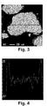
- a photocopy of a Comp image is shown in Fig. 1
- a photocopy of an elemental mapping image of Mg is shown in Fig. 2
- a photocopy of an elemental mapping image of Al is shown in Fig. 3
- a result of Mg line analysis determined along the line shown in Fig. 2 is shown in Fig. 4
- a result of Al line analysis determined along the line shown in Fig. 3 is shown in Fig. 5 .
- the sectional surface of the same hydrogen storage alloy powder was observed in FE-EPMA (manufactured by JEOL LTD., trade name JXA8500F) at a magnification of 350x, and an elemental mapping image of Mg was obtained.
- the contrast and level of the Mg elemental mapping image were adjusted for apparent observation of the contrasting densities of Mg. Regions with a higher Mg concentration compared to the inside the alloy powder were observed at the outermost surface of the alloy powder. In a Mg-poor region deeper inside than that region, regions with still poorer Mg compared to the surrounding regions were observed in insular manner.
- the regions with richer Mg compared to the inside and located at the outermost surface of the alloy powder, the insular regions with poorer Mg compared to the surrounding regions and located deeper inside the alloy powder than the above region, and the remaining regions inside the alloy powder were quantitatively analyzed under the conditions described above. It was determined that the composition of the regions with richer Mg compared to the inside and located at the outermost surface was La 0.63 Sm 0.12 Zr 0.01 Mg 0.24 Ni 2.96 Al 0.23 .
- the composition of the insular regions with poorer Mg was La 0.75 Sm 0.15 Zr 0.01 Mg 0.09 Ni 3.60 Al 0.34 , and the compositions of the remaining regions inside the alloy powder were La 0.68 SM 0.13 Zr 0.01 Mg 0.18 Ni 3.11 Al 0.17 and La 0.70 Sm 0.14 Zr 0.01 Mg 0.15 Ni 3.32 Al 0.18 .
- the regions with richer Mg compared to the inside and located at the outermost surface were the Mg-rich/Ni-poor regions, and the other regions were the Mg/Ni-containing regions.
- the insular regions with poorer Mg has a composition with an Al molar ratio not less than 1.20 times and not more than 2.00 times the Al molar ratio (0.20) of the overall composition of the alloy powder La 0.66 Sm 0.13 Zr 0.01 Mg 0.20 Ni 3.42 Al 0.20 , and surrounded by the regions having a composition with an Al molar ratio not less than 0.50 times and not more than 1.00 time (the said remaining regions, La 0.68 Sm 0.13 Zr 0.01 Mg 0.18 Ni 3.11 Al 0.17 , La 0.70 Sm 0.14 Zr 0.01 Mg 0.15 Ni 3.32 Al 0.18 ).
- Table 1 The results are shown in Table 1.
- the Mg, Ni, and Al molar ratios of the Mg-rich/Ni-poor regions with respect to the Mg, Ni, and Al molar rations in formula (1), respectively, and the Mg, Ni, and Al molar ratios of the Mg/Ni-containing regions with respect to the Mg, Ni, and Al molar rations in formula (1), respectively, calculated from the above results, are shown in Table 4.
- the thickness and long axis diameter of the Mg-rich/Ni-poor regions, and the proportion of the Mg-rich/Ni-poor regions in the circumferential length of the alloy powder were determined to be 6 ⁇ m, 30 ⁇ m, and 18%, respectively. These results are shown in Table 7.
- the battery characteristics of the hydrogen storage alloy powder thus obtained were determined in the following manner. The results of the evaluation of the battery characteristics are shown in Table 7.
- the charge/discharge was effected using a charge/discharge device (manufactured by KEISOKUKI CENTER CO., LTD., trade name BS2500-05R1) by repeating 100 times the cycle of charging at a current of 150 mA per 1g of the hydrogen storage alloy for 170 minutes, taking a break for 10 minutes, and discharging to a mercury oxide electrode at a current of 150 mA per 1 g of the hydrogen storage alloy to -0.7 V.
- a charge/discharge device manufactured by KEISOKUKI CENTER CO., LTD., trade name BS2500-05R1
- Cycle characteristics discharge capacity at 100 ⁇ th cycle / maximum discharge capacity ⁇ 100
- Hydrogen storage alloy powder was prepared in the same way as in Example 1 except that the composition of the starting materials was changed to obtain hydrogen storage alloy powder of the composition shown in Tables 1 to 3.
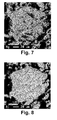
- a sectional surface of the hydrogen storage alloy powder prepared in Example 2 is shown in Fig. 6 as a photocopy of a Comp image taken in EPMA, a photocopy of the Mg elemental mapping image of the powder is shown in Fig. 7 , and a photocopy of the Al elemental mapping image of the powder is shown in Fig. 8 .
- the sectional surface of the same hydrogen storage alloy powder was observed in FE-EPMA in the same way as in Example 1, and the results are shown in Tables 1 to 3.
- Tables 1 to 3 in the column headed the composition of the Mg/Ni-containing regions, when the Mg/Ni-containing regions included at least region (a') having a composition with an Al molar ratio not less than 1.20 times and not more than 2.00 times the Al molar ratio of formula (1) representing the overall composition of the alloy powder, and region (b') having a composition with an Al molar ratio not less than 0.50 times and not more than 1.00 time the Al molar ratio of formula (1), with region (a') being present in insular manner, surrounded by region (b'), the compositional formula was marked with "Al rich".
- compositional formula marked with "Al rich” in the column of the composition of the Mg/Ni-containing regions means that the insular regions were not observed in the Mg mapping image.
- the compositional formulae not marked with "Al rich” are set out in the order of the region closer to the alloy powder surface toward the region closer to the center of the powder, inside of the Mg-rich/Ni-poor regions.
- FIG. 14 A photocopy of the Mg elemental mapping image obtained by observation in FE-EPMA of a sectional surface of the hydrogen storage alloy powder prepared in Example 22 is shown in Fig. 14 .
- the areas indicated with arrows (1) to (4) in Fig. 14 were quantitatively analyzed for each constitutive element. It was determined that area (1) was the Mg-rich/Ni-poor region, and areas (2) to (4) were the Mg/Ni-containing regions.
- Area (4) was the Mg/Ni-containing region having a composition with an Al molar ratio not less than 1.20 times and not more than 2.00 times the Al molar ratio (0.15) of the overall composition (La 0.45 Gd 0.10 Pr 0.06 Nd 0.19 Mg 0.20 Ni 3.30 Al 0.15 ) of the hydrogen storage alloy powder prepared in Example 22, present in insular manner, and surrounded by the regions having a composition with an Al molar ratio not less than 0.50 times and not more than 1.00 time (areas (2) and (3)).
- the Mg, Ni, and Al molar ratios of the Mg-rich/Ni-poor regions with respect to the Mg, Ni, and Al molar rations in formula (1), respectively, and the Mg, Ni, and Al molar ratios of the Mg/Ni-containing regions with respect to the Mg, Ni, and Al molar rations in formula (1), respectively, determined and calculated in the same way as in Example 1, are shown in Tables 4 to 6.
- Hydrogen storage alloy powder was prepared in the same way as in Example 1 except that the composition of the starting materials was changed, and the casting of the starting materials without Mg was carried out using a copper mold to obtain an ingot of 20 mm thick, to thereby obtain a hydrogen storage alloy powder of the composition shown in Table 3.
- Table 3 The results of observation in FE-EPMA of a sectional surface of the hydrogen storage alloy powder in the same way as in Example 1 is shown in Table 3.
- the Mg, Ni, and Al molar ratios of the Mg-rich/Ni-poor regions with respect to the Mg, Ni, and Al molar rations in formula (1), respectively, and the Mg, Ni, and Al molar ratios of the Mg/Ni-containing regions with respect to the Mg, Ni, and Al molar rations in formula (1), respectively, determined and calculated in the same way as in Example 1, are shown in Table 6.
- the thickness and long axis diameter of the Mg-rich/Ni-poor regions, and the proportion of the Mg-rich/Ni-poor regions in the circumferential length of the alloy powder determined in the same way as in Example 1, and the battery characteristics are shown in Table 9.
- Hydrogen storage alloy powder was prepared in the same way as in Example 1 except that the composition of the starting materials was changed, and the duration of the heat treatment originally carried out at 970 °C for 12 hours was changed to 3 hours (Examples 44, 47, and 50) 6 hours (Examples 45, 48, and 51), and 9 hours (Examples 46, 49, and 52), to thereby obtain a hydrogen storage alloy powder of the composition shown in Table 3.
- Table 3 The results of observation in FE-EPMA of a sectional surface of the hydrogen storage alloy powder in the same way as in Example 1 is shown in Table 3.
- FIG. 15 A photocopy of the Mg mapping image obtained by observation in FE-EPMA of a sectional surface of the hydrogen storage alloy powder prepared in Example 44 is shown in Fig. 15 .
- this alloy powder no Mg/Ni-containing region was observed inside the alloy powder, which is poorer in Mg compared to the surrounding regions and present in insular manner.
- the areas indicated with arrows (1) to (4) in Fig. 15 were quantitatively analyzed for each constitutive element. It was determined that area (1) was the Mg-rich/Ni-poor region, and areas (2) to (4) were the Mg/Ni-containing regions.
- the Mg, Ni, and Al molar ratios of the Mg-rich/Ni-poor regions with respect to the Mg, Ni, and Al molar rations in formula (1), respectively, and the Mg, Ni, and Al molar ratios of the Mg/Ni-containing regions with respect to the Mg, Ni, and Al molar rations in formula (1), respectively, determined and calculated in the same way as in Example 1, are shown in Table 6.
- the thickness and long axis diameter of the Mg-rich/Ni-poor regions, and the proportion of the Mg-rich/Ni-poor regions in the circumferential length of the alloy powder determined in the same way as in Example 1, and the battery characteristics are shown in Table 9.
- a photocopy of the Mg elemental mapping is shown in Fig. 10
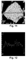
- a photocopy of the Al elemental mapping is shown in Fig. 11
- a result of Mg line analysis determined along the line shown in Fig. 10 is shown in Fig. 12
- a result of Al line analysis determined along the line shown in Fig. 11 is shown in Fig. 13 .
- Hydrogen storage alloy powder was prepared in the same way as in Comparative Example 1 except that the composition of the starting materials was changed to obtain a hydrogen storage alloy powder of the composition shown in Table 3.
- a sectional surface of the hydrogen storage alloy powder in FE-EPMA in the same way as in Example 1 no Mg-rich/Ni-poor region was observed at the outermost surface of the alloypowder.
- Hydrogen storage alloy powder was prepared in the same way as in Comparative Example 1 except that the composition of the starting materials was changed, and a copper mold was used in the casting to obtain an ingot of 20 mm thick, to thereby obtain a hydrogen storage alloy powder of the composition shown in Table 3.
- a sectional surface of the hydrogen storage alloy powder in FE-EPMA in the same way as in Example 1 no Mg-rich/Ni-poor region was observed at the outermost surface of the alloy powder.
Abstract
Description
- The present invention relates to a hydrogen storage alloy powder, an anode for a nickel-hydrogen rechargeable battery, and a nickel-hydrogen rechargeable battery.
- A nickel-hydrogen rechargeable battery with an anode containing a hydrogen storage alloy has a higher energy density than a nickel-cadmium rechargeable battery, and places only a small burden on the environment due to absence of toxic Cd. Nickel-hydrogen rechargeable batteries are used in portable devices such as digital cameras and electric tools as well as in electric vehicles and hybrid electric vehicles. Various battery characteristics are desired depending on their applications.
- As an anode material for a nickel-hydrogen rechargeable battery, there have been used a LaNi5 type hydrogen storage alloy, which is a rare earth-Ni intermetallic compound having CaCu5 crystal structure as the main phase, and a hydrogen storage alloy containing Ti, Zr, V, and Ni as constituent elements and having a Laves crystal structure as the main phase.
- Rare earth-Mg-Ni based hydrogen storage alloys have recently been put into practical use. Nickel-hydrogen rechargeable batteries employing this alloy as an anode material are known to have a large capacity.
-
Patent Publication 1 reports that surface acid treatment of a hydrogen storage alloy containing rare earths, nickel, magnesium, and aluminum provides a hydrogen storage alloy having a higher surface content of each of the nickel, magnesium, and aluminum elements with respect to the total rare earths compared to the corresponding content inside the alloy. The publication discloses that a nickel-hydrogen rechargeable battery employing such a hydrogen storage alloy in its anode has high rate discharge performance at low temperatures, and is inhibited from decrepitation due to alloy cracking resulting from charging/discharging, to prevent deterioration of the cycle life. -
Patent Publication 2 discloses that charge/discharge reaction in an alkaline aqueous solution of a nickel-hydrogen battery fabricated with an electrode containing La-Mg-Ni based hydrogen storage alloy particles and Sn, results in Sn-containing and Mg-containing compounds precipitated on the alloy particle surfaces, which increases the discharge capacity and improves the cycle characteristics of the nickel-hydrogen battery. - Patent Publication 1:
JP-2007-63597-A - Patent Publication 2:
JP-2009-64698-A - The nickel-hydrogen rechargeable batteries employing the hydrogen storage alloys disclosed in
Patent Publications - It is an object of the present invention to provide hydrogen storage alloy powder that is capable of providing a nickel-hydrogen rechargeable battery with simultaneous excellent in initial activity, discharge capacity, and cycle characteristics, which properties have conventionally been in a trade-off relationship.
- It is another object of the present invention to provide a nickel-hydrogen rechargeable battery that is excellent in all of initial activity, discharge capacity, and cycle characteristics, as well as an anode for such a rechargeable battery.
- According to the present invention, there is provided hydrogen storage alloy powder of a composition represented by formula (1):
R1-aMgaNibAlcMd
wherein R stands for at least one element selected from rare earth elements including Sc and Y, Zr, Hf, and Ca; M stands for at least one element selected from elements other than R, Mg, Ni, and Al, a satisfies 0.005 ≤ a ≤ 0.40, b satisfies 3.00 ≤ b ≤ 4.50, c satisfies 0 ≤ c ≤ 0.50, d satisfies 0 ≤ d ≤ 1.00, and b+c+d satisfies 3.00 ≤ b+c+d ≤ 4.50,
wherein said alloy powder has at its outermost surface a Mg-rich/Ni-poor region having a composition with a Mg molar ratio higher than that in formula (1) (value represented by a in formula (1)) and a Ni molar ratio lower than that in formula (1) (value represented by b in formula (1)), and has inside a Mg/Ni-containing region having a composition with a Mg molar ratio lower than that of said Mg-rich/Ni-poor region and a Ni molar ratio higher than that of said Mg-rich/Ni-poor region. - According to the present invention, there are also provided an anode for a nickel-hydrogen rechargeable battery employing the above-mentioned hydrogen storage alloy powder, and a nickel-hydrogen rechargeable battery employing the anode.
- The hydrogen storage alloy powder according to the present invention (sometimes referred to as the alloy powder hereinbelow) has the particular composition, the particular Mg-rich/Ni-poor region at its outermost surface, and the particular Mg/Ni-containing region inside the alloy powder, so that, when the alloy powder is used in an anode of a nickel-hydrogen rechargeable battery, the initial activity, discharge capacity, and cycle characteristics of the rechargeable battery are all improved concurrently.
-
Fig. 1 is a photocopy of a Comp image of a sectional structure of the hydrogen storage alloy powder prepared in Example 1. -
Fig. 2 is a photocopy of a Mg mapping image of the sectional structure of the hydrogen storage alloy powder prepared in Example 1. -
Fig. 3 is a photocopy of an Al mapping image of the sectional structure of the hydrogen storage alloy powder prepared in Example 1. -
Fig. 4 shows a result of a Mg line analysis of the sectional structure of the hydrogen storage alloy powder prepared in Example 1. -
Fig. 5 shows a result of an Al line analysis of the sectional structure of the hydrogen storage alloy powder prepared in Example 1. -
Fig. 6 is a photocopy of a Comp image of a sectional structure of the hydrogen storage alloy powder prepared in Example 2. -
Fig. 7 is a photocopy of a Mg mapping image of the sectional structure of the hydrogen storage alloy powder prepared in Example 2. -
Fig. 8 is a photocopy of an Al mapping image of the sectional structure of the hydrogen storage alloy powder prepared in Example 2. -
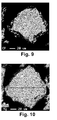
Fig. 9 is a photocopy of a Comp image of a sectional structure of the hydrogen storage alloy powder prepared in Comparative Example 1. -
Fig. 10 is a photocopy of a Mg mapping image of the sectional structure of the hydrogen storage alloy powder prepared in Comparative Example 1. -
Fig. 11 is a photocopy of an Al mapping image of the sectional structure of the hydrogen storage alloy powder prepared in Comparative Example 1. -
Fig. 12 shows a result of a Mg line analysis of the sectional structure of the hydrogen storage alloy powder prepared in Comparative Example 1. -
Fig. 13 shows a result of an Al line analysis of the sectional structure of the hydrogen storage alloy powder prepared in Comparative Example 1. -
Fig. 14 is a photocopy of a Mg mapping image of the sectional structure of the hydrogen storage alloy powder prepared in Example 22. -
Fig. 15 is a photocopy of a Mg mapping image of the sectional structure of the hydrogen storage alloy powder prepared in Example 44. - The present invention will now be explained in detail.
- The alloy composition of the hydrogen storage alloy powder according to the present invention is represented by formula (1):
R1-aMgaNibAlcMd
- In formula (1), R stands for at least one element selected from rare earth elements including Sc and Y, Zr, Hf, and Ca. It is particularly preferred that one, two or more of La, Nd, Pr, Sm, Y, and Zr are contained. La tends to lower the equilibrium pressure of the alloy upon hydrogen absorption/desorption, whereas Nd, Pr, Sm, Y, and Zr tend to raise the same.
- In formula (1), 1-a denotes the content of R, and satisfies 0.60 ≤ 1-a ≤ 0.995, preferably 0.75 ≤ 1-a ≤ 0.99, more preferably 0.85 ≤ 1-a ≤ 0.99.
- In formula (1), a denotes the content of Mg, and satisfies 0.005 ≤ a ≤ 0.40, preferably 0.01 ≤ a ≤ 0.25, more preferably 0.01 ≤ a ≤ 0.15. At a lower Mg content, sufficient hydrogen storage capacity is not attained and, when the alloy is used for a rechargeable battery, the discharge capacity of the battery may be low. At a higher Mg content, sufficient corrosion resistance is not attained and, when the alloy is used for a rechargeable battery, the cycle characteristics of the battery may be poor. Mg tends to increase the hydrogen storage capacity, and to raise the equilibrium pressure of the alloy powder upon hydrogen absorption/desorption.
- In formula (1), b denotes the content of Ni, and satisfies 3.00 ≤ b ≤4.50, preferably 3.00 ≤ b ≤4.00, more preferably 3.00 ≤ b ≤ 3.80. At a lower Ni content, decrepitation is apt to proceed and, when the alloy is used for a rechargeable battery, the cycle characteristics of the battery may be low. At a higher Ni content, sufficient hydrogen storage capacity is not attained and, when the alloy is used for a rechargeable battery, sufficient discharge capacity may not be attained.
- In formula (1), c denotes the content of Al, and satisfies 0 ≤ c ≤ 0.50, preferably 0.05 ≤ c ≤0.50, more preferably 0.05 ≤ c ≤ 0.30. Al is not indispensable but, improves corrosion resistance when contained. When the alloy is used for a rechargeable battery, Al contributes to improvement in cycle characteristics of the battery. Al also tends to lower the equilibrium pressure of the alloy powder upon hydrogen absorption/desorption and, when the alloy is used for a rechargeable battery, contributes to improvement in the initial capacity. On the other hand, at a higher Al content, sufficient hydrogen storage capacity is not attained, and Al segregation may obstruct sufficient corrosion resistance.
- In formula (1), M stands for at least one element selected from elements other than R, Mg, Ni, and Al, and may be any element that contributes to fine adjustment of characteristics of a battery depending on its application. Specific examples of element M may be at least one element selected from Ti, V, Nb, Ta, Cr, Mo, W, Mn, Fe, Co, Cu, Zn, B, Ga, Sn, Sb, In, C, Si, and P, preferably at least one element selected from Ti, Nb, Mo, W, Mn, Fe, Co, Cu, B, and Sn. For example, with at least one element selected from Ti, Nb, Mo, W, Fe, Cu, Sn, and B, decrepitation may be inhibited or elution of Al into an electrolyte may be inhibited.
- In formula (1), d denotes the content of element M, and satisfies 0 ≤ d ≤ 1.00, preferably 0 ≤ d ≤ 0.50. Element M is not indispensable, but may be contained when fine adjustment of battery characteristics is desired depending on the application of the battery.
- In formula (1), b+c+d denotes the content of the components other than R and Mg. These components primarily affect decrepitation and, when the alloy is used for a rechargeable battery, contribute to improvement in cycle characteristics of the battery. b+c+d satisfies 3.00 ≤ b+c+d ≤ 4.50, preferably 3.00 ≤ b+c+d ≤ 4.00, more preferably 3.00 ≤ b+c+d ≤ 3.80.
- In the present invention, the composition of the alloy powder is confirmed by quantitative analysis with ICP (Inductively Coupled Plasma).
- The hydrogen storage alloy powder according to the present invention has, at its outermost surface, a Mg-rich/Ni-poor region having a composition with a Mg molar ratio higher than that in formula (1) (value represented by a in formula (1)) and a Ni molar ratio lower than that in formula (1) (value represented by b in formula (1)), and has, inside, a Mg/Ni-containing region having a composition with a Mg molar ratio lower than that of the Mg-rich/Ni-poor region and a Ni molar ratio higher than that of the Mg-rich/Ni-poor region.
- When Al is contained in the hydrogen storage alloy powder of the present invention, the content thereof in the Mg-rich/Ni-poor region is arbitrary, and the region preferably has a composition with an Al molar ratio higher than that in formula (1) (value represented by c in formula (1)). The Al content in the Mg/Ni-containing region is also arbitrary, and the region preferably has a region having a composition with an Al molar ratio lower than that in the Mg-rich/Ni-poor region.
- It is assumed that, with the Mg-rich/Ni-poor region being present at the outermost surface of the alloy powder, hydrogen migrates smoothly between the Mg-rich/Ni-poor region and the inside of the alloy powder. As a result, when the alloy is used for a rechargeable battery, excellent initial activity, discharge capacity, and cycle characteristics of the battery may all be attained concurrently.
- The Mg-rich/Ni-poor region has a composition with a Mg molar ratio usually not less than 1.05 times and not more than 1.90 times, preferably not less than 1.05 times and not more than 1.50 times the Mg molar ratio in formula (1), and a Ni molar ratio usually not less than 0.45 times and not more than 0.95 times, preferably not less than 0.50 times and not more than 0.95 times the Ni molar ratio in formula (1).
- The Mg-rich/Ni-poor region is usually present not all over but partially over the outermost surface of the alloy powder. It is assumed that, with this particular structure, the boundaries between the Mg-rich/Ni-poor region and the remaining region on the outermost surface of the alloy powder act to smoothen the hydrogen migration between the Mg-rich/Ni-poor region and the inside of the alloy powder.
- The Mg-rich/Ni-poor region exists as a region having a thickness of usually not less than 1 µm and not more than 40 µm, preferably not less than 2 µm and not more than 40 µm, as measured from the outermost surface toward the center of the alloy powder. The long axis diameter of the Mg-rich/Ni-poor region is preferably not less than 5 µm and not more than 60 µm. The proportion of the Mg-rich/Ni-poor region in the circumferential length of the alloy powder is preferably 1 to 60 %, more preferably 1 to 30 %.
- The Mg-rich/Ni-poor region and the Mg/Ni-containing region are confirmed using an elemental mapping of Mg obtained by observation of a sectional surface of the hydrogen storage alloy powder in FE (Field Emission) -EPMA (Electron Probe Micro Analyzer) at a magnification of 350×. The contrast, level, and the like parameters of the Mg elemental mapping image are adjusted to emphasize the contrasting densities of Mg. When a region at the outermost surface of the alloy powder is observed to have a Mg concentration higher than that of the inside of the alloy powder, that region as well as a region deeper inside than that region is quantitatively analyzed for the elements contained in the alloy powder at an accelerating voltage of 15 kV, sample current of 5.0 × 10⁻⁸ A, beam diameter φ of not larger than 1 µm and in scan-off. When the Mg and Ni molar ratios in these regions are found to fall within the above-mentioned ranges, respectively, the regions are confirmed to be the Mg-rich/Ni-poor region and the Mg/Ni-containing region, respectively.
- The thickness from the outermost surface and the long axis diameter of the Mg-rich/Ni-poor region may be determined by randomly selecting five particles from the alloy powder having the Mg-rich/Ni-poor region observed on the sectional surface of the alloy powder as mentioned above, determining the maximum thicknesses and the long axis diameters of all the Mg-rich/Ni-poor regions present on the alloy powder surfaces, and taking an average for each. The proportion of the Mg-rich/Ni-poor region in the circumferential length of the outermost surface is calculated by adding up the lengths of the Mg-rich/Ni-poor regions occupying the circumferential lengths of the same five particles, and dividing the sum with the total of the circumferential lengths of the five particles.
- The Mg-rich/Ni-poor region is assumed to be a phase mainly composed of any of the MgZn2 type crystal structure, MgCu2 type crystal structure (the two may sometimes be referred to collectively as the 1-2 phase hereinbelow), CeNi3 type crystal structure, PuNi3 type crystal structure (the two may sometimes be referred to collectively as the 1-3 phase hereinbelow), Ce2Ni7 type crystal structure, Gd2Co7 type crystal structure (the two may sometimes be referred to collectively as the 2-7 phase), or a crystal structure similar to these. The crystal structure of the Mg/Ni-containing region is assumed to be composed mainly of any of the 1-3 phase, the 2-7 phase, Ce5Ni19 type crystal structure, Pr5Co19 type crystal structure (the two may sometimes be referred to collectively as the 5-19 phase hereinbelow), or a crystal structure similar to these. These crystal structures are presumed to be formed by partial substitution of the atoms at the B-site of the unit cell of the CaCu5 type crystal structure (sometimes referred to as the 1-5 phase hereinbelow) with the atoms of the A-site to generate an antiphase boundary, which is a kind of stacking fault, in the crystal structure. It is assumed that the hydrogen storage alloy powder of the present invention has crystal structures wherein the B-site becomes richer from the Mg-rich/Ni-poor region at the outermost surface toward inside of the alloy powder (including the Mg/Ni-containing region). For example, when the Mg-rich/Ni-poor region is mainly of the 1-2 phase or a crystal structure similar to this, the crystal structure inside the alloy powder is assumed to vary through the phases mainly of the 1-3, 2-7, and 5-19 phases toward the 1-5 phase when observed from near the Mg-rich/Ni-poor region into deeper inside the alloy powder. Such variation of the crystal structures from the surface toward the center is assumed to be one of the causes for smooth hydrogen absorption/desorption. It is also assumed that the variation acts to relieve the strain generated upon expansion/contraction of the alloy powder due to hydrogen absorption/desorption. These are assumed to result in the simultaneous excellence in initial activity, discharge capacity, and cycle characteristics when the alloy powder is used for a rechargeable battery.
- The above-mentioned crystal structures are deduced from the results of the quantitative analyses in FE-EPMA of each element in the Mg-rich/Ni-poor region and the inside of the alloy powder. For example, according to the results in Example 18 to be discussed later, the AB ratio (the sum of b, c, and d in formula (1)) of the Mg-rich/Ni-poor region is 1.71, and the ratio varies through 3.13 and 3.56 toward the inside of the alloy powder. This leads to the assumption that the Mg-rich/Ni-poor region is a phase similar to the 1-2 phase, and the phases inside the alloy powder vary through the ones similar to the 1-3, 2-7, and 5-19 phases toward the center. Similarly, in Example 52, the AB ratio varies through 3.16, 3.17, 3.36, and 3.90 from the Mg-rich/Ni-poor region into the inside of the alloy powder. This leads to the assumption that the Mg-rich/Ni-poor region is of a phase similar to the 1-3 phase, and the phases inside the alloy powder vary through the ones similar to the 1-3, 2-7, 5-19, and 1-5 phases toward the center. That is, it is seen that the measured AB ratios are not integer values, and vary from about 2 to about 5 from the Mg-rich/Ni-poor region toward the inside of the alloy powder. In this specification, the crystal structures from the 1-2 to 5-19 phases having different AB ratios are specifically mentioned. Recent reports have shown crystal structures having an AB ratio between the 5-19 and 1-5 phases. These are the crystal structures wherein the atoms at the B-site of the 1-5 phase unit cell are substituted with the atoms of the A-site at a certain cycle. The present invention does not exclude such crystal structures.
- It is usually preferred that the Mg/Ni-containing region includes at least two regions having compositions with different Mg molar ratios.
- The at least two regions of the Mg/Ni-containing region include regions (a) and (b), wherein region (a) is of a composition with a Mg molar ratio not less than 0 times and not more than 0.50 times the Mg molar ratio in formula (1), and region (b) is of a composition with a Mg molar ratio more than 0.50 times and not more than 0.95 times the Mg molar ratio in formula (1). Such at least two Mg/Ni-containing regions may be present inside the alloy powder in any distribution.
- It is preferred that the Mg-rich/Ni-poor region and the at least two Mg/Ni-containing regions indicate concentration gradients of decreasing Mg molar ratio and increasing Ni molar ratio from the outermost surface toward the center of the alloy powder. It is assumed that, with a structure having such concentration gradients, the crystal structures are increasingly B-site rich from the outermost surface toward the center of the alloy powder to smoothen the hydrogen migration, and act to relieve the strain generated upon expansion/contraction of the alloy due to hydrogen absorption/desorption.
- When the hydrogen storage alloy powder of the present invention contains Al, and has a composition with an Al molar ratio higher than that in formula (1), the Al molar ratio is preferably not less than 1.05 times and not more than 2.00 times the Al molar ratio in formula (1).
- When the hydrogen storage alloy powder of the present invention contains Al, and has at least two Mg/Ni-containing regions, it is preferred that the at least two regions include regions (a') and (b'), wherein region (a') is of a composition with an Al molar ratio not less than 1.20 times and not more than 2.00 times the Al molar ratio in formula (1), and region (b') is of a composition with an Al molar ratio not less than 0.50 times and not more than 1.00 time of the Al molar ratio in formula (1). It is more preferred for inhibition of alloy powder decrepitation that region (a') is present in insular manner, surrounded by region (b'). Here, region (a) and region (a') or region (b) and region (b') as the Mg/Ni-containing region may be the same or different.
- The hydrogen storage alloy powder of the present invention has a mean volume diameter (MV) of preferably 20 to 100 µm, more preferably 40 to 80 µm. When this alloy powder, together with an electrically conductive material, a binder, and the like, is used for producing an anode for a nickel-hydrogen rechargeable battery, the alloy powder may be packed at a high density.
- The hydrogen storage alloy powder according to the present invention may be prepared, for example, by the following method.
- First, alloy powder having the composition of the objective hydrogen storage alloy powder except for at least Mg is prepared. This alloy powder may be prepared by any process without limitation, and may be by a conventional process, such as strip casting with a single roll, twin rolls, or a disk, or metal mold casting.
- When strip casting is employed, starting materials are provided having a particular alloy composition excluding Mg. Then, in an inert gas atmosphere, the starting materials are heated to melt into an alloy melt, and the alloy melt is poured onto a water-cooled copper roll and rapidly cooled and solidified into alloy flakes. On the other hand, when metal mold casting is employed, the alloy melt obtained by the above process is poured into a water-cooled copper mold and rapidly cooled and solidified into an ingot. The cooling rate is different between strip casting and metal mold casting, and for obtaining an alloy having uniform compositional distribution with little segregation, strip casting is preferred. Further, for preparing an alloy having uniform compositional distribution with little segregation, the alloy without Mg thus obtained may be subjected to heat treatment.
- Next, the cast alloy is pulverized into alloy powder. The pulverization may be carried out in a conventional pulverizer. In order for the alloy powder without Mg to undergo smooth diffusion and reaction of Mg in the subsequent heat treatment step to be discussed later, the particle size in MV of the alloy powder is preferably 20 to 1000 µm, more preferably 20 to 400 µm, most preferably 20 to 100 µm.
- Separately from the production of this alloy powder, powder of Mg metal or a Mg-containing alloy is prepared. The powder of Mg metal may be prepared by pulverizing bare Mg metal in a conventional pulverizer. The powder of a Mg-containing alloy may be prepared in the same way as the alloy powder without Mg. For preventing evaporation of Mg in the subsequent heat treatment step to be discussed later, the melting point of the Mg-containing alloy is preferably as low as possible and not higher than the boiling point of Mg metal. Elements to be combined with Mg metal may be, for example, at least one element selected from Al, Cu, Zn, Ga, Sn, and In. Particularly preferred are Mg-Al, Mg-In, and Mg-Zn alloys having the alloy melting point lower than the melting point of Mg metal. R to be combined with Mg metal may be La, Ce, Pr, Nd, Sm, and Mm (misch metal) containing these, Eu, Yb, or the like. In order for the alloy powder without Mg to undergo smooth diffusion and reaction of Mg in the subsequent heat treatment step to be discussed later, the particle size of the powder of Mg metal or the Mg-containing alloy in mean particle diameter (D50) is preferably 20 to 2000 µm, more preferably 20 to 1500 µm.
- Next, the alloy powder without Mg and the powder of Mg metal or the Mg-containing alloy are blended so as to give a composition of a desired hydrogen storage alloy powder, and mixed. It is preferred to make as homogenous mixture as possible for efficient diffusion and reaction of Mg in the subsequent heat treatment step to be discussed later. The mixing may be carried out in a conventional mixer, such as a rotary mixer of a double-cone or V-type, or a stirring mixer having vanes or screws. A pulverizer such as a ball mill or an attritor mill may also be used to pulverize and mix the alloy powder without Mg and the powder of Mg metal or the Mg-containing alloy.
- The diffusion and reaction of Mg is usually carried out at a relatively low temperature, i.e., 400 to 1090 °C, so that an amount of the components such as Mg will not evaporate. Strictly, however, taking the yield of each component into account, the alloy powder without Mg and the powder of Mg metal or the Mg-containing alloy are mixed so as to obtain an alloy of the desired composition.
- The mixture thus obtained is subjectedtoheat treatment preferably at 400 to 1090 °C for 0.5 to 240 hours. This heat treatment may be carried out in a conventional heat-treatment furnace in which the atmosphere may be controlled. The heat treatment may be carried out with the mixture being mixed, for example, in a rotary mixer such as a rotary kiln. During the heat treatment, Mg in the powder of Mgmetal or the Mg-containing alloy is diffused into and reacted inside the alloy powder without Mg, resulting in hydrogen storage alloy powder of the present invention. The heat treatment is preferably carried out at such temperature and for such duration that the evaporation of Mg is suppressed and the diffusion and reaction easily proceed. Specifically, the temperature of the heat treatment is preferably at 500 to 1080 °C, and the duration of the heat treatment is preferably 1 to 24 hours. Since Mg is prone to oxidation, the heat treatment is preferably carried out in vacuo or in an inert gas atmosphere, more preferably in an inert gas atmosphere under pressure. In this case, not only oxidation but also evaporation of Mg may be prevented.
- The heat treatment may be carried out in two or more steps in the temperature range of 400 to 1090 °C, for example, by holding the mixture in a temperature region slightly above the melting point of the powder of Mg metal or the Mg-containing alloy, raising the temperature, and holding the mixture in a higher temperature region. In this way, the diffusion and reaction may be effected more uniformly. Specifically, the mixture may be held at 660 to 750 °C for 0.1 to 2.0 hours, and then at 900 to 1080 °C for 4 to 24 hours.
- In case part of the alloy powder after the heat treatment is aggregated, or has a powder particle size larger than the size suitable for an anode material for a nickel-hydrogen rechargeable battery, the hydrogen storage alloy powder obtained by the heat treatment may be subjected to loosening or pulverization. Generally, the particle size in MV after the loosening or pulverization is preferably 20 to 100 µm, more preferably 40 to 80 µm. The loosening or the pulverization may be carried out in a conventional pulverizer such as a feather mill, hammer mill, ball mill, or attritor mill.
- The anode for a nickel-hydrogen rechargeable battery according to the present invention contains the hydrogen storage alloy powder of the present invention thus prepared. The hydrogen storage alloy powder of the present invention may be subj ected to a conventional treatment, such as surface coating, for example, by plating or with a high polymer, or surface treatment with, for example, an acid or alkaline solution, prior to use depending on the desired characteristics.
- The content of the hydrogen storage alloy powder in the anode for a nickel-hydrogen rechargeable battery of the present invention is preferably not less than 80 mass%, more preferably not less than 95 mass%, of the total amount of the materials constituting the anode, such as an electrically conductive material and a binder, exclusive of the collector.
- The electrically conductive material may be a conventional one and may be, for example, carbon black such as acetylene black and furnace black, a carbonaceous material such as graphite, copper, nickel, or cobalt. The binder may be a conventional one and may be, for example, carboxymethyl cellulose, polyvinyl alcohol, polyvinylbutyral, polyvinylpyrrolidone, polyethylene oxide, polytetrafluoroethylene (PTFE), ethylene-tetrafluoride-propylene hexafluoride copolymer (FEP).
- The collector may be made of, for example, punched metal or foam metal. An anode for a nickel-hydrogen rechargeable battery is generally prepared by a so-called paste method, thus a punched metal is used. Such a paste-type anode may be prepared by mixing the hydrogen storage alloy powder of the present invention, the binder mentioned above, and optionally an electrically conductive material, an antioxidant, a surfactant, a thickener and/or the like, with water as a solvent into a paste, applying the paste to a collector, packing, drying, roller-pressing, and the like steps.
- The anode for a nickel-hydrogen rechargeable battery of the present invention may have a water-repellent layer or an electrically conductive layer formed on its surface as desired. Such a layer may be formed by a conventional method. For example, the former may be formed by application of a fluororesin dispersion or the like followed by drying, whereas the latter by plating or the like.
- The nickel-hydrogen rechargeable battery according to the present invention has the anode for a nickel-hydrogen rechargeable battery of the present invention. The remaining structures may be conventional.
- The nickel-hydrogen rechargeable battery of the present invention may be in a variety of shapes, including a cylinder, a laminate, or a coin. In any shape, a nickel-hydrogen rechargeable battery is fabricated by placing a series of electrodes prepared by laminating an anode, a separator, and a cathode, in a stainless can or the like. In case of a cylindrical shape, the can generally acts as an anode terminal, so that the anode is connected to the anode terminal by rolling the series of electrodes into a roll with the anode outside, and inserting the roll in the can. The cathode is generally connected to a cathode terminal with a lead wire.
- The separator may be made of, for example, a non-woven fabric of polymer fibers such as of nylon, polypropylene, or polyethylene, or a porous polymer film such as of polyethylene or polypropylene.
- The cathode usually contains a nickel oxide and may be, for example, a non-sintered nickel electrode. A non-sintered nickel electrode is prepared by mixing nickel hydroxide, a binder, and optionally cobalt hydroxide, cobalt monoxide, and/or cobalt metal, with water as a solvent into a paste, applying the paste to a collector of, for example, foammetal, packing, drying, roller-pressing, and the like steps.
- In the container in which the series of electrodes has been placed, a 6 to 8 N potassium hydroxide solution as an alkaline electrolyte is introduced. An alkaline electrolyte containing lithium hydroxide or sodium hydroxide may also be used. The container is usually equipped with a gasket for sealing the battery, and a safety valve which operates upon pressure buildup in the battery.
- The present invention will now be explained in detail with reference to Examples and Comparative Examples, which do not intend to limit the present invention.
- Starting materials of the composition of the hydrogen storage alloy powder as shown in Table 1 other than Mg were measured out, and melted in a high-frequency melting furnace in an argon gas atmosphere into an alloy melt. The alloy melt, at a pouring temperature of 1400 °C, was rapidly cooled and solidified by strip casting in a single roll casting system having a water-cooled copper roll, into flakes having an average thickness of 0.4 mm. The obtained flakes were pulverized in a ball mill into alloy powder having an MV of 85 µm. The composition of the obtained alloy was analyzed with ICP, and found to be La0.66SM0.13Zr0.01Ni3.42Al0.20.
- The alloy powder thus obtained was thoroughly mixed with Mg metal powder having a mean particle diameter (D50) of 110 µm in a mortar. The obtained mixture was held in an argon gas atmosphere at 700 °C for 30 minutes, and then at an elevated temperature of 970 °C for 12 hours. The composition of the obtained alloy powder was analyzed with ICP and found to be La0.66Sm0.13Zr0.01Mg0.20Ni3.42Al0.20. The heat treated alloy powder was loosened in a mortar to obtain hydrogen storage alloy powder having an MV of 70 µm.
- A sectional surface of the heat-treated hydrogen storage alloy powder was observed in EPMA (manufactured by JEOL LTD., trade name JXA8800) at a magnification of 500×. A photocopy of a Comp image is shown in
Fig. 1 , a photocopy of an elemental mapping image of Mg is shown inFig. 2 , a photocopy of an elemental mapping image of Al is shown inFig. 3 , a result of Mg line analysis determined along the line shown inFig. 2 is shown inFig. 4 , and a result of Al line analysis determined along the line shown inFig. 3 is shown inFig. 5 . - Further, the sectional surface of the same hydrogen storage alloy powder was observed in FE-EPMA (manufactured by JEOL LTD., trade name JXA8500F) at a magnification of 350x, and an elemental mapping image of Mg was obtained. The contrast and level of the Mg elemental mapping image were adjusted for apparent observation of the contrasting densities of Mg. Regions with a higher Mg concentration compared to the inside the alloy powder were observed at the outermost surface of the alloy powder. In a Mg-poor region deeper inside than that region, regions with still poorer Mg compared to the surrounding regions were observed in insular manner. The regions with richer Mg compared to the inside and located at the outermost surface of the alloy powder, the insular regions with poorer Mg compared to the surrounding regions and located deeper inside the alloy powder than the above region, and the remaining regions inside the alloy powder were quantitatively analyzed under the conditions described above. It was determined that the composition of the regions with richer Mg compared to the inside and located at the outermost surface was La0.63Sm0.12Zr0.01Mg0.24Ni2.96Al0.23. the composition of the insular regions with poorer Mg was La0.75Sm0.15Zr0.01Mg0.09Ni3.60Al0.34, and the compositions of the remaining regions inside the alloy powder were La0.68SM0.13Zr0.01Mg0.18Ni3.11Al0.17 and La0.70Sm0.14Zr0.01Mg0.15Ni3.32Al0.18. Thus, it was confirmed that the regions with richer Mg compared to the inside and located at the outermost surface were the Mg-rich/Ni-poor regions, and the other regions were the Mg/Ni-containing regions. It was further confirmed that the insular regions with poorer Mg has a composition with an Al molar ratio not less than 1.20 times and not more than 2.00 times the Al molar ratio (0.20) of the overall composition of the alloy powder La0.66Sm0.13Zr0.01Mg0.20Ni3.42Al0.20, and surrounded by the regions having a composition with an Al molar ratio not less than 0.50 times and not more than 1.00 time (the said remaining regions, La0.68Sm0.13Zr0.01Mg0.18Ni3.11Al0.17, La0.70Sm0.14Zr0.01Mg0.15Ni3.32Al0.18). The results are shown in Table 1. The Mg, Ni, and Al molar ratios of the Mg-rich/Ni-poor regions with respect to the Mg, Ni, and Al molar rations in formula (1), respectively, and the Mg, Ni, and Al molar ratios of the Mg/Ni-containing regions with respect to the Mg, Ni, and Al molar rations in formula (1), respectively, calculated from the above results, are shown in Table 4.
- The thickness and long axis diameter of the Mg-rich/Ni-poor regions, and the proportion of the Mg-rich/Ni-poor regions in the circumferential length of the alloy powder were determined to be 6 µm, 30 µm, and 18%, respectively. These results are shown in Table 7.
- The battery characteristics of the hydrogen storage alloy powder thus obtained were determined in the following manner. The results of the evaluation of the battery characteristics are shown in Table 7.
- 0.15 g of the hydrogen storage alloy powder and 0.45 g of carbonyl nickel powder were thoroughly mixed in a mortar, and the resulting mixture was pressed at 2000 kgf/cm2 into a pellet of 10 mm diameter. The pellet was held between two sheets of nickel mesh, and the periphery of the mesh sheets was spot-welded to press-contact the mesh sheets. Further, a nickel lead wire was spot-welded to the mesh sheets, to thereby prepare an anode. The obtained anode and a sintered nickel electrode as a counter electrode were immersed in a 8N aqueous KOH solution, and subjected to charge/discharge cycle test at 25 °C.
- The charge/discharge was effected using a charge/discharge device (manufactured by KEISOKUKI CENTER CO., LTD., trade name BS2500-05R1) by repeating 100 times the cycle of charging at a current of 150 mA per 1g of the hydrogen storage alloy for 170 minutes, taking a break for 10 minutes, and discharging to a mercury oxide electrode at a current of 150 mA per 1 g of the hydrogen storage alloy to -0.7 V.
- The cycle characteristics were defined as follows, based on the maximum discharge capacity and the discharge capacity at the 100th cycle determined in the charge/discharge discussed above.

- Hydrogen storage alloy powder was prepared in the same way as in Example 1 except that the composition of the starting materials was changed to obtain hydrogen storage alloy powder of the composition shown in Tables 1 to 3. A sectional surface of the hydrogen storage alloy powder prepared in Example 2 is shown in
Fig. 6 as a photocopy of a Comp image taken in EPMA, a photocopy of the Mg elemental mapping image of the powder is shown inFig. 7 , and a photocopy of the Al elemental mapping image of the powder is shown inFig. 8 . - Further, the sectional surface of the same hydrogen storage alloy powder was observed in FE-EPMA in the same way as in Example 1, and the results are shown in Tables 1 to 3. In Tables 1 to 3, in the column headed the composition of the Mg/Ni-containing regions, when the Mg/Ni-containing regions included at least region (a') having a composition with an Al molar ratio not less than 1.20 times and not more than 2.00 times the Al molar ratio of formula (1) representing the overall composition of the alloy powder, and region (b') having a composition with an Al molar ratio not less than 0.50 times and not more than 1.00 time the Al molar ratio of formula (1), with region (a') being present in insular manner, surrounded by region (b'), the compositional formula was marked with "Al rich". No compositional formula marked with "Al rich" in the column of the composition of the Mg/Ni-containing regions, means that the insular regions were not observed in the Mg mapping image. The compositional formulae not marked with "Al rich" are set out in the order of the region closer to the alloy powder surface toward the region closer to the center of the powder, inside of the Mg-rich/Ni-poor regions.
- A photocopy of the Mg elemental mapping image obtained by observation in FE-EPMA of a sectional surface of the hydrogen storage alloy powder prepared in Example 22 is shown in
Fig. 14 . The areas indicated with arrows (1) to (4) inFig. 14 were quantitatively analyzed for each constitutive element. It was determined that area (1) was the Mg-rich/Ni-poor region, and areas (2) to (4) were the Mg/Ni-containing regions. Area (4) was the Mg/Ni-containing region having a composition with an Al molar ratio not less than 1.20 times and not more than 2.00 times the Al molar ratio (0.15) of the overall composition (La0.45Gd0.10Pr0.06Nd0.19Mg0.20Ni3.30Al0.15) of the hydrogen storage alloy powder prepared in Example 22, present in insular manner, and surrounded by the regions having a composition with an Al molar ratio not less than 0.50 times and not more than 1.00 time (areas (2) and (3)). - The Mg, Ni, and Al molar ratios of the Mg-rich/Ni-poor regions with respect to the Mg, Ni, and Al molar rations in formula (1), respectively, and the Mg, Ni, and Al molar ratios of the Mg/Ni-containing regions with respect to the Mg, Ni, and Al molar rations in formula (1), respectively, determined and calculated in the same way as in Example 1, are shown in Tables 4 to 6.
- The thickness and long axis diameter of the Mg-rich/Ni-poor regions, and the proportion of the
- Mg-rich/Ni-poor regions in the circumferential length of the alloy powder determined in the same way as in Example 1, and the battery characteristics are shown in Tables 7 to 9.
- Hydrogen storage alloy powder was prepared in the same way as in Example 1 except that the composition of the starting materials was changed, and the casting of the starting materials without Mg was carried out using a copper mold to obtain an ingot of 20 mm thick, to thereby obtain a hydrogen storage alloy powder of the composition shown in Table 3. The results of observation in FE-EPMA of a sectional surface of the hydrogen storage alloy powder in the same way as in Example 1 is shown in Table 3.
- The Mg, Ni, and Al molar ratios of the Mg-rich/Ni-poor regions with respect to the Mg, Ni, and Al molar rations in formula (1), respectively, and the Mg, Ni, and Al molar ratios of the Mg/Ni-containing regions with respect to the Mg, Ni, and Al molar rations in formula (1), respectively, determined and calculated in the same way as in Example 1, are shown in Table 6.
- The thickness and long axis diameter of the Mg-rich/Ni-poor regions, and the proportion of the Mg-rich/Ni-poor regions in the circumferential length of the alloy powder determined in the same way as in Example 1, and the battery characteristics are shown in Table 9.
- Hydrogen storage alloy powder was prepared in the same way as in Example 1 except that the composition of the starting materials was changed, and the duration of the heat treatment originally carried out at 970 °C for 12 hours was changed to 3 hours (Examples 44, 47, and 50) 6 hours (Examples 45, 48, and 51), and 9 hours (Examples 46, 49, and 52), to thereby obtain a hydrogen storage alloy powder of the composition shown in Table 3. The results of observation in FE-EPMA of a sectional surface of the hydrogen storage alloy powder in the same way as in Example 1 is shown in Table 3.
- A photocopy of the Mg mapping image obtained by observation in FE-EPMA of a sectional surface of the hydrogen storage alloy powder prepared in Example 44 is shown in
Fig. 15 . In this alloy powder, no Mg/Ni-containing region was observed inside the alloy powder, which is poorer in Mg compared to the surrounding regions and present in insular manner. The areas indicated with arrows (1) to (4) inFig. 15 were quantitatively analyzed for each constitutive element. It was determined that area (1) was the Mg-rich/Ni-poor region, and areas (2) to (4) were the Mg/Ni-containing regions. - The Mg, Ni, and Al molar ratios of the Mg-rich/Ni-poor regions with respect to the Mg, Ni, and Al molar rations in formula (1), respectively, and the Mg, Ni, and Al molar ratios of the Mg/Ni-containing regions with respect to the Mg, Ni, and Al molar rations in formula (1), respectively, determined and calculated in the same way as in Example 1, are shown in Table 6.
- The thickness and long axis diameter of the Mg-rich/Ni-poor regions, and the proportion of the Mg-rich/Ni-poor regions in the circumferential length of the alloy powder determined in the same way as in Example 1, and the battery characteristics are shown in Table 9.
- In order to obtain an alloy of the same composition as the hydrogen storage alloy powder of Example 1, all the starting materials including Mg metal were simultaneously mixed, and subjected to strip casting in the same way as in Example 1 to obtain flakes. The flakes thus obtained were heat treated in an argon gas atmosphere at 950 °C for 6 hours. The heat-treated flakes were pulverized in a ball mill, to obtain hydrogen storage alloy powder having an MV of 70 µm. The composition of the obtained alloy powder was analyzed with ICP and found to be La0.66Sm0.13Zr0.01Mg0.20Ni3.42Al0.20. A photocopy of a Comp image of the obtained hydrogen storage alloy powder taken in EPMA is shown in
Fig. 9 , a photocopy of the Mg elemental mapping is shown inFig. 10 , a photocopy of the Al elemental mapping is shown inFig. 11 , a result of Mg line analysis determined along the line shown inFig. 10 is shown inFig. 12 , and a result of Al line analysis determined along the line shown inFig. 11 is shown inFig. 13 . - As a result of observation of a sectional surface of the hydrogen storage alloy powder in FE-EPMA in the same way as in Example 1, no Mg-rich/Ni-poor region was observed at the outermost surface of the alloypowder. Quantitative analysis of two regions inside the alloy powder revealed that the region closer to the surface had a composition La0.65Sm0.12Zr0.01Mg0.20Ni3.40Al0.21, and the region closer to the center had a composition La0.66Sm0.12Zr0.01Mg0.20Ni3.43Al0.20. The battery characteristics were determined in the same way as in Example 1. The results are shown in Table 9.
- Hydrogen storage alloy powder was prepared in the same way as in Comparative Example 1 except that the composition of the starting materials was changed to obtain a hydrogen storage alloy powder of the composition shown in Table 3. As a result of observation of a sectional surface of the hydrogen storage alloy powder in FE-EPMA in the same way as in Example 1, no Mg-rich/Ni-poor region was observed at the outermost surface of the alloypowder. Quantitative analysis of two regions inside the alloy powder in the same way as in Comparative Example 1 revealed that the region closer to the surface had a composition La0.15Pr0.47Nd0.24Mg0.15Ni3.31Co0.14Al0.08, and the region closer to the center had a composition La0.16Pr0.46Nd0.25Mg0.15Ni3.30Co0.16Al0.07. The battery characteristics were determined in the same way as in Example 1. The results are shown in Table 9.
- Hydrogen storage alloy powder was prepared in the same way as in Comparative Example 1 except that the composition of the starting materials was changed, and a copper mold was used in the casting to obtain an ingot of 20 mm thick, to thereby obtain a hydrogen storage alloy powder of the composition shown in Table 3. As a result of observation of a sectional surface of the hydrogen storage alloy powder in FE-EPMA in the same way as in Example 1, no Mg-rich/Ni-poor region was observed at the outermost surface of the alloy powder. Quantitative analysis of two regions inside the alloy powder in the same way as in Comparative Example 1 revealed that the region closer to the surface had a composition La0.62SM0.14Zr0.01Mg0.13Ni3.44Al0.10, and the region closer to the center had a composition La0.69Sm0.14Zr0.01Mg0.17Ni3.37Al0.15. The battery characteristics were determined in the same way as in Example 1. The results are shown in Table 9.
Table 1 Alloy composition of hydrogen storage alloy powder Composition of Mg-rich/Ni-poor region Composition of Mg/Ni-containing region Example 1 La0.66Sm0.13Zr0.01Mg0.20Ni3.12Al0.20 La0.63Sm0.12Zr0.01Mg0.24Ni2.96Al0.23 La0.68Sm0.13Zr0.01Mg0.18Ni3.11Al0.17 La0.70Sm0.14Zr0.01Mg0.15Ni3.32Al0.18 La0.75Sm0.15Zr0.01Mg0.09Ni3.60Al0.31(Al rich) Example 2 La0.59Sm0.20Zr0.01Mg0.20Ni3.12Al0.15 La0.55Sm0.19Zr0.01Mg0.25Ni3.21Al0.17 La0.60Sm0.20Zr0.01Mg0.19Ni3.23Al0.11 La0.62Sm0.21Zr0.01Mg0.16Ni3.33Al0.11 La0.68Sm0.23Zr0.01Mg0.08Ni3.49Al0.21(Al rich) Example 3 La0.57Ce0.05Sm0.14Zr0.01Mg0.23Ni3.12Al0.10 La0.50Sm0.12Ce0.04Zr0.01Mg0.33Ni2.88Al0.12 La0.60Sm0.15Ce0.05Zr0.01Mg0.19Ni3.11Al0.09 La0.67Sm0.16Ce0.06Zr0.01Mg0.10Ni3.58Al0.17(Al rich) Example 4 La0.60Sm0.27Mg0.13Ni3.65Al0.14 La0.59Sm0.27Mg0.14Ni1.80Al0.13 La0.62Sm0.28Mg0.10Ni3.15Al0.12 La0.65Sm0.29Mg0.06Ni3.89Al0.20(Al rich) Example 5 La0.20Nd0.40Sm0.30Mg0.10Ni3.48Al0.18 La0.19Sm0.28Nd0.37Mg0.16Ni3.20Al0.22 La0.20Sm0.31Nd0.41Mg0.08Ni3.38Al0.16 La0.21Sm0.32Nd0.43Mg0.04Ni3.66Al0.34(Al rich) Example 6 La0.32Nd0.29Sm0.26Mg0.13Ni3.50Al0.18 La0.29Sm0.24Nd0.27Mg0.20Ni3.21Al0.21 La0.33Sm0.27Nd0.30Mg0.10Ni3.35Al0.17 La0.35Sm0.28Nd0.32Mg0.05Ni3.75Al0.29(Al rich) Example 7 Nd0.87Mg0.13Ni3.31Al0.18 Nd0.85Mg0.15Ni1.63Al0.18 Nd0.89Mg0.11Ni2.99Al0.15 Nd0.93Mg0.07Ni3.46Al0.37(Al rich) Example 8 Pr0.22Nd0.65Mg0.13Ni3.31Al0.18 Pr0.20Nd0.60Mg0.20Ni2.96Al0.21 Pr0.23Nd0.66Mg0.11Ni3.14Al0.16 Pr0.24Nd0.72Mg0.01Ni3.66Al0.29(Al rich) Example 9 La0.78Zr0.02Mg0.20Ni3.52Al0.20 La0.73Zr0.02Mg0.25Ni3.21Al0.21 La0.80Zr0.02Mg0.18Ni3.39Al0.18 La0.83Zr0.02Mg0.15Ni3.49Al0.19 La0.87Zr0.02Mg0.08Ni3.69Al0.35(Al rich) Example 10 La0.82Mg0.18Ni3.55Al0.20 La0.81Mg0.19Ni3.18Al0.24 La0.83Mg0.17Ni3.37Al0.16 La0.88Mg0.12Ni3.44Al0.17 La0.95Mg0.05Ni3.57Al0.32(Al rich) Example 11 La0.80Mg0.20Ni3.60Al0.20 La0.73Mg0.27Ni3.23Al0.26 La0.82Mg0.18Ni3.45Al0.13 La0.85Mg0.15Ni3.62Al0.15 La0.91Mg0.09Ni3.76Al0.28(Al rich) Example 12 La0.80Mg0.20Ni3.55Al0.17 La0.71Mg0.26Ni2.35Al0.23 La0.82Mg0.18Ni3.27Al0.16 La0.85Mg0.15Ni3.46Al0.16 La0.97Mg0.03Ni3.78Al0.33(Al rich) Example 13 La0.83Mg0.17Ni3.55Co0.05Al0.15 La0.74Mg0.26Ni3.10Co0.01Al0.16 La0.84Mg0.16Ni3.26Co0.05Al0.14 La0.94Mg0.06Ni3.68Co0.05Al0.27(Al rich) Example 14 La0.15Pr0.45Nd0.25Mg0.15Ni3.30Co0.15Al0.08 La0.14Pr0.40Nd0.22Mg0.24Ni2.76Co0.13Al0.08 La0.15Pr0.46Nd0.25Mg0.14Ni2.97Co0.14Al0.07 La0.15Pr0.46Nd0.25Mg0.14Ni2.85Co0.14Al0.08 La0.16Pr0.49Nd0.27Mg0.08Ni3.33Co0.15Al0.12(Al rich) Example 15 La0.18Pr0.42Nd0.27Mg0.13Ni3.38MN0.06Co0.05Al0.08 La0.17Pr0.38Nd0.25Mg0.20Ni2.61Mn0.05Co0.04Al0.07 La0.19Pr0.43Nd0.28Mg0.10Ni2.86Mn0.05Co0.04Al0.06 La0.18Pr0.43Nd0.27Mg0.12Ni2.71Mn0.05Co0.14Al0.08 La0.20Pr0.48Nd0.31Mg0.01Ni3.12Mn0.07Co0.05Al0.09 Example 16 La0.15Y0.05Pr0.32Nd0.32Mg0.16Ni3.21Al0.17 La0.15Y0.05Pr0.30Nd0.30Mg0.20Ni1.58Al0.18 La0.15Y0.05Pr0.32Nd0.33Mg0.15Ni2.98Al0.16 La0.16Y0.05Pr0.35Nd0.35Mg0.09Ni3.34Al0.20(Al rich) Example 17 La0.55Pr0.06Nd0.19Mg0.20Ni3.20Cu0.10Al0.10 La0.46Pr0.05Nd0.16Mg0.33Ni2.90Cu0.09Al0.15 La0.57Pr0.06Nd0.20Mg0.17Ni2.94Cu0.09Al0.08 La0.61Pr0.07Nd0.21Mg0.11Ni3.29Cu0.10Al0.17(Al rich) Example 18 La0.55Pr0.06Nd0.19Mg0.20Ni3.27Fe0.05Al0.08 La0.50Pr0.06Nd0.18Mg0.26Ni1.61Fe0.02Al0.08 La0.58Pr0.06Nd0.20Mg0.16Ni3.02Fe0.05Al0.06 La0.66Pr0.06Nd0.23Mg0.05Ni3.42Fe0.05Al0.09 Table 2 Alloy composition of hydrogen storage alloy powder Composition of Mg-rich//Ni-poor region Composition of Mg/Ni-containing region Example 19 La0.55Pr0.06Nd0.19Mg0.20Ni3.27Sn0.05Al0.08 La0.47Pr0.05Nd0.16Mg0.32Ni2.88Sn0.04Al0.16 La0.59Pr0.06Nd0.20Mg0.15Ni3.14Sn0.05Al0.06 La0.65Pr0.07Nd0.23Mg0.05Ni3.29Sn0.05Al0.09 Example 20 La0.53Pr0.06Nd0.19Mg0.22Ni3.27Si0.03Al0.10 La0.44Pr0.05Nd0.16Mg0.35Ni2.88Si0.03Al0.13 La0.55Pr0.06Nd0.19Mg0.20Ni3.11Si0.03Al0.08 La0.61Pr0.07Nd0.22Mg0.10Ni3.36Si0.03Al0.16(Al rich) Example 21 La0.51Pr0.08Nd0.21Mg0.20Ni3.30Nb0.02Al0.10 La0.47Pr0.08Nd0.20Mg0.25Ni2.89Nb0.02Al0.18 La0.52Pr0.08Nd0.22Mg0.18Ni3.05Nb0.02Al0.07 La0.59Pr0.09Nd0.21Mg0.08Ni3.41Nb0.02Al0.15(Al rich) Example 22 La0.45Gd0.10Pr0.06Nd0.19Mg0.20Ni3.30Al0.15 La0.43Gd0.10Pr0.06Nd0.18Mg0.23Ni2.96Al0.19 La0.47Gd0.10Pr0.06Nd0.19Mg0.18Ni3.06Al0.12 La0.49Gd0.11Pr0.06Nd0.20Mg0.14Ni3.28Al0.14 La0.52Gd0.12Pr0.07Nd0.22Mg0.07Ni3.45Al0.25(Al rich) Example 23 La0.56Pr0.07Nd0.20Mg0.17Ni3.35Al0.10 La0.55Pr0.07Nd0.20Mg0.18Ni1.65Al0.11 La0.58Pr0.07Nd0.20Mg0.15Ni3.24Al0.09 La0.63Pr0.08Nd0.22Mg0.07Ni3.50Al0.18(Al rich) Example 24 La0.51Pr0.08Nd0.21Mg0.20Ni3.30Al0.15 La0.50Pr0.08Nd0.21Mg0.21Ni3.02Al0.16 La0.51Pr0.08Nd0.22Mg0.19Ni3.11Al0.13 La0.58Pr0.09Nd0.25Mg0.08Ni3.51Al0.26(Al rich) Example 25 La0.55Pr0.06Nd0.19Mg0.20Ni3.30Al0.20 La0.53Pr0.06Nd0.18Mg0.23Ni2.87Al0.23 La0.57Pr0.06Nd0.20Mg0.17Ni2.99Al0.19 La0.59Pr0.06Nd0.20Mg0.15N3.26Al0.19 La0.63Pr0.07Nd0.22Mg0.08Ni3.14Al0.32(Al rich) Example 26 La0.50Pr0.06Nd0.19Mg0.25Ni3.30Al0.10 La0.38Pr0.05Nd0.15Mg0.42Ni2.61Al0.14 La0.53Pr0.06Nd0.20Mg0.21Ni2.80Al0.09 La0.60Pr0.07Nd0.23Mg0.10Ni3.45Al0.13(Al rich) Example 27 La0.60Pr0.25Mg0.15Ni3.45Al0.16 La0.52Pr0.22Mg0.26Ni3.20Al0.20 La0.61Pr0.26Mg0.13Ni3.35Al0.44 La0.66Pr0.27Mg0.07Ni3.86Al0.30(Al rich) Example 28 La0.70Pr0.15Mg0.15Ni3.49Al0.16 La0.68Pr0.15Mg0.17Ni1.70Al0.46 La0.71Pr0.15Mg0.14Ni3.23Al0.14 La0.76Pr0.16Mg0.08Ni3.31Al0.26(Al rich) Example 29 La0.62Pr0.25Mg0.13Ni3.45Al0.16 La0.55Pr0.22Mg0.23Ni3.11Al0.19 La0.63Pr0.25Mg0.12Ni3.29Al0.15 La0.65Pr0.26Mg0.09Ni3.61Al0.26(Al rich) Example 30 La0.61Pr0.22Mg0.17Ni3.45Al0.16 La0.58Pr0.21Mg0.21Ni1.65Al0.16 La0.62Pr0.22Mg0.16Ni3.18Al0.15 La0.66Pr0.24Mg0.10Ni3.49Al0.26(Al rich) Example 31 La0.73Pr0.12Mg0.15Ni3.59Al0.16 La0.66Pr0.11Mg0.23Ni3.21Al0.18 La0.74Pr0.12Mg0.14Ni3.30Al0.14 La0.80Pr0.13Mg0.07Ni3.71Al0.28(Al rich) Example 32 La0.55Pr0.20Sm0.10Mg0.15Ni3.45Al0.16 La0.53Sm0.10Pr0.20Mg0.17Ni1.67Al0.17 La0.56Sm0.10Pr0.20Mg0.14Ni3.31Al0.13 La0.60Sm0.11Pr0.22Mg0.07Ni3.50Al0.26(Al rich) Example 33 La0.58Pr0.06Nd0.14Mg0.22Ni3.30Al0.20 La0.49Pr0.05Nd0.12Mg0.34Ni2.99Al0.21 La0.60Pr0.06Nd0.14Mg0.20Ni3.20Al0.17 La0.65Pr0.07Nd0.16Mg0.12Ni3.51Al0.32(Al rich) Example 34 La0.56Pr0.20Mg0.24Ni3.45Al0.16 La0.46Pr0.16Mg0.38Ni3.11Al0.20 La0.59Pr0.21Mg0.20Ni3.24Al0.15 La0.66Pr0.24Mg0.10Ni3.47Al0.30(Al rich) Example 35 La0.60Pr0.12Y0.05Mg0.23Ni3.45Al0.16 La0.56Pr0.11Y0.05Mg0.28Ni1.65Al0.15 La0.61Pr0.12Y0.05Mg0.22Ni3.34Al0.14 La0.70Pr0.14Y0.06Mg0.10Ni3.55Al0.31(Al rich) Example 36 La0.65Pr0.10Mg0.25Ni3.59Al0.16 La0.52Pr0.08Mg0.40Ni3.27Al0.22 La0.68Pr0.11Mg0.21Ni3.34Al0.15 La0.77Pr0.12Mg0.11Ni3.65Al0.25(Al rich) Table 3 Alloy composition of hydrogen storage alloy powder Composition of Mg-rich/Ni-poor region Composition of Mg/Ni-containing region Example 37 La0.67Sm0.16Zr0.01Mg0.16Ni3.42Al0.13 La0.65Sm0.15Zr0.01Mg0.19Ni3.08Al0.16 La0.68Sm0.16Zr0.01Mg0.15Ni3.19Al0.11 La0.74Sm0.18Zr0.01Mg0.07Ni3.45Al0.18(Al rich) Example 38 La0.45Sm0.47Mg0.08Ni3.55Al0.07 La0.42Sm0.43Mg0.15Ni1.67Al0.06 La0.46Sm0.48Mg0.06Ni3.40Al0.05 La0.44Sm0.46Mg0.10Ni3.32Al0.06 La0.47Sm0.49Mg0.05Ni3.68Al0.12 Example 39 La0.32Pr0.37Nd0.17Mg0.14Ni3.32Al0.08 La0.29Pr0.33Nd0.15Mg0.23Ni1.52Al0.07 La0.33Pr0.38Nd0.17Mg0.12Ni2.97Al0.07 La0.32Pr0.38Nd0.17Mg0.13Ni3.15Al0.07 La0.35Pr0.40Nd0.19Mg0.08Ni3.39Al0.21 Example 40 La0.55Pr0.06Nd0.19Mg0.20Ni3.30Al0.10 La0.49Pr0.05Nd0.17Mg0.29Ni2.87Al0.17 La0.56Pr0.06Nd0.19Mg0.19Ni3.00Al0.09 La0.62Pr0.07Nd0.22Mg0.09Ni3.55Al0.17(Al rich) Example 41 Pr0.45Nd0.45Sm0.08Mg0.02Ni3.40Al0.07 Pr0.45Nd0.44Sm0.08Mg0.03Ni3.01Al0.09 Pr0.45Nd0.46Sm0.08Mg0.01Ni3.31Al0.06 Pr0.46Nd0.46Sm0.08Ni3.38Al0.07 Pr0.45Nd0.47Sm0.08Ni3.41Al0.07 Example 42 La0.78Pr0.10Mg0.12Ni3.40Al0.25 La0.73Pr0.09Mg0.18Ni3.10Al0.44 La0.80Pr0.10Mg0.10Ni3.21Al0.22 La0.83Pr0.11Mg0.06Ni3.31Al0.22 La0.86Pr0.11Mg0.03Ni3.51Al0.26 Example 43 La0.60Sm0.19Ca0.01Mg0.20Ni3.30Co0.10Mn0.10Sn0.10Al0.05 La0.53Sm0.17Ca0.01Mg0.29Ni2.91Co0.09Mn0.09Sn0.09Al0.07 La0.63Sm0.20Ca0.01Mg0.16Ni2.95Co0.09Mn0.09Sn0.09Al0.04 La0.68Sm0.21Ca0.01Mg0.10Ni3.19Co0.10Mn0.10Sn0.10Al0.04 La0.73Sm0.22Ca0.01Mg0.04Ni3.42Co0.10Mn0.10Sn0.10Al0.05 Example 44 La0.25Nd0.25Sm0.40Mg0.10Ni3.35Al0.10 La0.22Nd0.22Sm0.42Mg0.11Ni2.64Al0.13 La0.24Nd0.24Sm0.46Mg0.06Ni3.19Al0.09 La0.24Nd0.24Sm0.48Mg0.04Ni3.29Al0.09 La0.25Nd0.25Sm0.49Mg0.01Ni3.45Al0.12 Example 45 La0.25Nd0.25Sm0.40Mg0.10Ni3.35Al0.10 La0.22Nd0.22Sm0.43Mg0.13Ni2.75Al0.12 La0.23Nd0.23Sm0.47Mg0.07Ni2.97Al0.09 La0.24Nd0.24Sm0.48Mg0.04Ni3.40Al0.09 La0.24Nd0.24Sm0.49Mg0.03Ni3.41Al0.11 Example 46 La0.25Nd0.25Sm0.40Mg0.10Ni3.35Al0.10 La0.22Nd0.22Sm0.44Mg0.12Ni2.81Al0.11 La0.23Nd0.23Sm0.45Mg0.09Ni2.86Al0.09 La0.24Nd0.24Sm0.46Mg0.06Ni3.05Al0.09 La0.24Nd0.24Sm0.48Mg0.04Ni3.40Al0.11 Example 47 Nd0.85Mg0.15Ni3.10Al0.10 Nd0.78Mg0.22Ni2.31Al0.17 Nd0.87Mg0.13Ni2.56Al0.07 Nd0.91Mg0.09Ni2.78Al0.09 Nd0.97Mg0.03Ni3.42Al0.12 Example 48 Nd0.85Mg0.15Ni3.10Al0.10 Nd0.80Mg0.20Ni2.45Al0.18 Nd0.89Mg0.11Ni2.69Al0.08 Nd0.93Mg0.07Ni2.89Al0.09 Nd0.95Mg0.05Ni3.31Al0.12 Example 49 Nd0.85Mg0.15Ni3.10Al0.10 Nd0.81Mg0.19Ni2.57Al0.13 Nd0.91Mg0.09Ni2.74Al0.07 Nd0.93Mg0.07Ni2.97Al0.09 Nd0.96Mg0.04Ni3.25Al0.12 Example 50 La0.50Nd0.45Mg0.05Ni3.65Al0.10 La0.49Nd0.44Mg0.07Ni3.32Al0.15 La0.51Nd0.45Mg0.04Ni3.44Al0.08 La0.52Nd0.47Mg0.04Ni3.54Al0.09 La0.53Nd0.47Ni3.68Al0.10 Example 51 La0.50Nd0.45Mg0.05Ni3.65Al0.10 La0.49Nd0.45Mg0.06Ni3.19Al0.14 La0.51Nd0.45Mg0.04Ni3.32Al0.08 La0.51Nd0.46Mg0.03Ni3.41Al0.08 La0.52Nd0.47Mg0.01Ni3.86Al0.11 Example 52 La0.50Nd0.45Mg0.05Ni3.65Al0.10 La0.19Nd0.45Mg0.06Ni3.02Al0.14 La0.51Nd0.45Mg0.04Ni3.09Al0.08 La0.51Nd0.46Mg0.03Ni3.27Al0.09 La0.52Nd0.46Mg0.02Ni3.79Al0.11 Com.Ex.1 La0.66Sm0.13Zr0.01Mg0.20Ni3.42Al0.20 - - Comp.Ex2 La0.15Pr0.45Nd0.25Mg0.15Ni3.30Al0.08 - - Comp.Ex3 La0.67Sm0.16Zr0.01Mg0.16Ni3.42Al0.13 - - Table 4 Mg-rich/Ni-poor region Mg/Ni-containing region 1 Mg/Ni-containing region 2 Mg/Ni-containing region 3 Mg/Mg in powder Ni / Ni in powder Al / Al in powder Mg/Mg in powder Ni / Ni in powder Al / Al in powder Mg/Mg in powder Ni / Ni in powder Al/ Al in powder Mg/Mgin powder Ni / Ni in powder Al / Al in powder Example 1 1.20 0.87 1.14 0.90 0.91 0.85 0.75 0.97 0.90 0.44 1.05 1.68 Example 2 1.25 0.94 1.13 0.95 0.94 0.93 0.80 0.97 0.93 0.40 1.02 1.40 Example 3 1.43 0.84 1.20 0.83 0.91 0.90 0.43 1.05 1.70 Example 4 1.08 0.49 0.93 0.77 0.95 0.86 0.46 1.07 1.43 Example 5 1.60 0.92 1.22 0.80 0.97 0.89 0.40 1.05 1.89 Example 6 1.54 0.92 1.17 0.77 0.96 0.94 0.38 1.07 1.61 Example 7 1.15 0.49 1.00 0.85 0.90 0.83 0.54 1.05 2.06 Example 8 1.54 0.89 1.17 0.85 0.95 0.89 0.31 1.11 1.61 Example 9 1.25 0.92 1.20 0.90 0.96 0.90 0.75 0.99 0.95 0.40 1.05 1.75 Example 10 1.06 0.90 1.20 0.94 0.95 0.80 0.67 0.97 0.85 0.28 1.01 1.60 Example 11 1.35 0.90 1.30 0.90 0.96 0.65 0.75 1.01 0.75 0.45 1.04 1.40 Example 12 1.30 0.66 1.35 0.90 0.92 0.94 0.75 0.97 0.94 0.15 1.06 1.94 Example 13 1.53 0.87 1.07 0.94 0.92 0.93 0.35 1.04 1.80 Example 14 1.60 0.84 1.00 0.93 0.90 0.88 0.93 0.86 1.00 0.53 1.01 1.50 Example 15 1.54 0.77 0.88 0.77 0.85 0.75 0.92 0.80 1.00 0.08 1.01 1.13 Example 16 1.25 0.49 1.06 0.94 0.93 0.94 0.56 1.04 1.18 Example 17 1.65 0.91 1.50 0.85 0.92 0.80 0.55 1.03 1.70 Example 18 1.30 0.49 1.00 0.80 0.92 0.75 0.25 1.05 1.13 Table 5 Mg-rich/Ni-poor region Mg/Ni-containing region 1 Mg/Ni-containing region 2 Mg/Ni-containing region 3 Mg/Mg in powder Ni / Ni in powder Al / Al in powder Mg/Mg in powder Ni / Ni in powder Al / Al in powder Mg/Mg in powder Ni / Ni in powder Al / Al in powder Mg/Mg in powder Ni / Ni in powder Al / Al in powder Example 19 1.60 0.88 2.00 0.75 0.96 0.75 0.25 1.01 1.13 Example 20 1.59 0.88 1.30 0.91 0.95 0.80 0.45 1.03 1.60 Example 21 1.25 0.88 1.80 0.90 0.92 0.70 0.40 1.03 1.50 Example 22 1.15 0.90 1.27 0.90 0.93 0.80 0.70 0.99 0.93 0.35 1.05 1.67 Example 23 1.06 0.49 1.10 0.88 0.97 0.90 0.41 1.04 1.80 Example 24 1.05 0.92 1.07 0.95 0.94 0.87 0.40 1.06 1.73 Example 25 1.15 0.87 1.25 0.85 0.91 0.95 0.75 0.99 0.95 0.40 1.04 1.60 Example 26 1.68 0.79 1.40 0.84 0.85 0.90 0.40 1.05 1.30 Example 27 1.73 0.93 1.25 0.87 0.97 0.88 0.47 1.12 1.88 Example 28 1.13 0.49 1.00 0.93 0.93 0.88 0.53 1.01 1.63 Example 29 1.77 0.90 1.19 0.92 0.95 0.94 0.69 1.05 1.63 Example 30 1.24 0.48 1.00 0.94 0.92 0.94 0.59 1.01 1.63 Example 31 1.53 0.89 1.13 0.93 0.92 0.88 0.47 1.03 1.75 Example 32 1.13 0.48 1.06 0.93 0.96 0.81 0.47 1.01 1.63 Example 33 1.55 0.91 1.05 0.91 0.97 0.85 0.55 1.06 1.60 Example 34 1.58 0.91 1.25 0.83 0.94 0.94 0.42 1.01 1.88 Example 35 1.22 0.48 0.94 0.96 0.97 0.88 0.43 1.03 2.13 Example 36 1.60 0.91 1.38 0.84 0.93 0.94 0.44 1.02 1.56 Table 6 Mg-rich/Ni-poor region Mg/Ni-containing region 1 Mg/Ni-Containing region 2 Mg/Ni-containing region 3 Mg/Mg in powder Ni / Ni in powder Al / Al in powder Mg/Mg in powder Ni / Ni in powder Al / Al in powder Mg/Mg in powder Ni / Ni in powder Al / Al in powder Mg/Mg in powder Ni / Ni in powder Al / Al in powder Example 37 1.19 0.90 1.23 0.94 0.93 0.85 0.44 1.01 1.38 Example 38 1.88 0.47 0.86 0.75 0.96 0.71 1.25 0.94 0.86 0.63 1.04 1.71 Example 39 1.64 0.46 0.88 0.86 0.89 0.88 0.93 0.95 0.88 0.57 1.02 2.63 Example 40 1.45 0.87 1.70 0.95 0.91 0.90 0.45 1.08 1.70 Example 41 1.50 0.89 1.29 0.50 0.97 0.86 0.00 0.99 1.00 0.00 1.00 1.00 Example 42 1.50 0.91 1.76 0.83 0.94 0.88 0.50 0.97 0.88 0.25 1.03 1.12 Example 43 1.45 0.88 1.40 0.80 0.89 0.80 0.50 0.97 0.80 0.20 1.04 1.00 Example 44 1.40 0.79 1.30 0.60 0.95 0.90 0.40 0.98 0.90 0.10 1.03 1.20 Example 45 1.30 0.82 1.20 0.70 0.89 0.90 0.40 0.93 0.90 0.30 1.02 1.10 Example 46 1.20 0.85 1.10 0.90 0.85 0.90 0.60 0.91 0.90 0.40 1.01 1.10 Example 47 1.47 0.75 1.70 0.87 0.83 0.70 0.60 0.90 0.90 0.20 1.10 1.20 Example 48 1.33 0.79 1.80 0.73 0.87 0.80 0.47 0.93 0.90 0.33 1.08 1.20 Example 49 1.27 0.83 1.30 0.60 0.88 0.70 0.47 0.96 0.90 0.27 1.05 1.20 Example 50 1.40 0.91 1.50 0.80 0.93 0.80 0.20 0.97 0.90 0.00 1.01 1.00 Example 51 1.20 0.87 1.40 0.80 0.91 0.80 0.60 0.93 0.80 0.20 1.06 1.10 Example 52 1.20 0.83 1.40 0.80 0.85 0.80 0.80 0.90 0.90 0.40 1.04 1.10 Table 7 Thickness of Mg-rich/Ni-poor region (µm) Long axis diameter of Mg-rich/Ni-poor region (µm) Proportion of Mg-rich/Ni-poor region in circumferential length of alloy powder (%) Discharge capacity (mAh/g) Cycle characteristics 1st 2nd 3rd Example 1 6 30 18 308 347 356 93 Example 2 5 18 12 305 344 354 92 Example 3 18 39 27 312 348 359 90 Example 4 3 11 5 297 332 342 92 Example 5 1 12 4 299 335 345 96 Example 6 3 15 6 302 336 347 95 Example 7 3 14 6 300 335 345 95 Example 8 3 14 8 301 330 342 96 Example 9 7 27 20 309 346 357 92 Example 10 5 22 18 312 348 359 93 Example 11 6 26 16 308 347 357 93 Example 12 6 28 17 307 346 355 92 Example 13 4 19 12 300 338 349 94 Example 14 4 16 11 297 330 340 90 Example 15 3 14 9 294 328 338 90 Example 16 4 19 14 296 332 341 93 Example 17 6 31 22 306 345 355 89 Example 18 6 29 22 306 342 354 89 Table 8 Thickness of Mg-rich/Ni-poor region (µm) Long axis diameter of Mg-rich/Ni-poor region (µm) Proportion of Mg-rich/Ni-poor region in circumferential length of alloy powder (%) Discharge capacity (mAh/g) Cycle characteristics 1st 2nd 3rd Example 19 9 33 23 309 347 357 89 Example 20 16 37 25 314 349 360 89 Example 21 10 21 27 307 347 357 90 Example 22 11 24 27 305 346 355 92 Example 23 5 18 14 300 335 347 91 Example 24 8 30 22 304 342 353 91 Example 25 8 32 24 306 344 354 93 Example 26 24 49 29 318 354 364 88 Example 27 4 15 12 301 338 348 91 Example 28 4 17 15 300 338 347 91 Example 29 2 13 9 300 337 346 92 Example 30 5 19 13 304 337 348 92 Example 31 4 12 10 299 335 345 92 Example 32 5 12 10 299 337 346 92 Example 33 30 47 24 312 349 359 86 Example 34 20 57 25 314 351 362 86 Example 35 18 33 42 316 352 364 85 Example 36 31 59 48 318 355 366 84 Table 9 Thickness of Mg-rich/Ni-poor region (µm) Long axis diameter of Mg-rich/Ni-poor region (µm) Proportion of Mg-rich/Ni-poor region in circumferential length of alloy powder (%) Discharge capacity (mAh/g) Cycle characteristics 1st 2nd 3rd Example 37 4 16 11 305 343 353 94 Example 38 1 10 3 296 329 340 90 Example 39 4 14 11 295 327 338 90 Example 40 9 21 19 305 346 356 90 Example 41 2 8 5 298 329 353 94 Example 42 7 14 7 308 349 358 93 Example 43 12 34 18 315 354 364 91 Example 44 15 13 7 321 358 369 90 Example 45 13 12 6 319 356 367 91 Example 46 8 10 5 315 353 365 93 Example 47 23 28 13 327 359 368 90 Example 48 20 26 12 322 357 366 91 Example 49 17 22 10 318 355 364 92 Example 50 6 12 6 302 342 354 98 Example 51 4 11 5 300 340 353 96 Example 52 5 9 4 299 338 353 96 Comp.Ex.1 - - - 277 328 338 83 Comp.Ex.2 - - - 247 317 318 83 Comp.Ex.3 - - - 278 325 335 84
Claims (14)
- Hydrogen storage alloy powder of a composition represented by formula (1):
R1-aMgaNibAlcMd
wherein R stands for at least one element selected from rare earth elements including Sc and Y, Zr, Hf, and Ca; M stands for at least one element selected from elements other than R, Mg, Ni, and Al, a satisfies 0.005 ≤ a ≤ 0.40, b satisfies 3.00 ≤ b ≤ 4.50, c satisfies 0 ≤ c ≤ 0.50, d satisfies 0 ≤ d ≤ 1.00, and b+c+d satisfies 3.00 ≤ b+c+d ≤ 4.50,
wherein said alloy powder has at its outermost surface a Mg-rich/Ni-poor region wherein a Mg molar ratio is higher than that in formula (1) (value represented by a in formula (1)) and a Ni molar ratio is lower than that in formula (1) (value represented by b in formula (1)), and has inside a Mg/Ni-containing region wherein a Mg molar ratio is lower than that of said Mg-rich/Ni-poor region and a Ni molar ratio is higher than that of said Mg-rich/Ni-poor region. - The hydrogen storage alloy powder according to claim 1, wherein said Mg-rich/Ni-poor region has a composition with a Mg molar ratio not less than 1.05 times and not more than 1.50 times the Mg molar ratio in formula (1), and a Ni molar ratio not less than 0.50 times and not more than 0.95 times the Ni molar ratio in formula (1).
- The hydrogen storage alloy powder according to claim 1 or 2, wherein as said Mg/Ni-containing region, at least two regions having compositions with different Mg molar ratios are present.
- The hydrogen storage alloy powder according to claim 3, wherein said at least two regions of the Mg/Ni-containing region comprise regions (a) and (b), wherein region (a) is of a composition with a Mg molar ratio not less than 0 time and not more than 0.50 times the Mg molar ratio in formula (1), and region (b) is of a composition with a Mg molar ratio more than 0.50 times and not more than 0.95 times the Mg molar ratio in formula (1).
- The hydrogen storage alloy powder according to any one of claims 1 to 4, wherein said Mg-rich/Ni-poor region is present as a region having a thickness of not less than 2 µm and not more than 40 µm, as measured from the outermost surface toward the center of the alloy powder.
- The hydrogen storage alloy powder according to any one of claims 3 to 5, wherein said Mg-rich/Ni-poor region and said at least two Mg/Ni-containing regions indicate concentration gradients of decreasing Mg molar ratio and increasing Ni molar ratio from the outermost surface toward the center of the alloy powder.
- The hydrogen storage alloy powder according to any one of claims 1 to 6, wherein said Mg-rich/Ni-poor region has a composition with an Al molar ratio higher than that in formula (1) (value represented by c in formula (1)), and said Mg/Ni-containing region comprises a region having a composition with an Al molar ratio lower than that in the Mg-rich/Ni-poor region.
- The hydrogen storage alloy powder according to any one of claims 1 to 7, wherein said Mg-rich/Ni-poor region has a composition with an Al molar ratio not less than 1.05 times and not more than 2.00 times the Al molar ratio in formula (1).
- The hydrogen storage alloy powder according to any one of claims 3 to 8, wherein said at least two regions of the Mg/Ni-containing region comprise regions (a') and (b'), wherein said region (a') is of a composition with an Al molar ratio not less than 1.20 times and not more than 2.00 times the Al molar ratio in formula (1), and said region (b') is of a composition with an Al molar ratio not less than 0.50 times and not more than 1.00 time the Al molar ratio in formula (1), with said region (a') being present in insular manner, surrounded by said region (b').
- The hydrogen storage alloy powder according to any one of claims 1 to 9 wherein, in formula (1), a satisfies 0.01 ≤ a ≤ 0.15, b satisfies 3.00 ≤ b ≤ 3.80, c satisfies 0.05 ≤ c ≤ 0.50, d satisfies 0 ≤ d ≤ 1.00, and b+c+d satisfies 3.00 ≤ b+c+d ≤ 3.80.
- The hydrogen storage alloy powder according to any one of claims 1 to 10, wherein said alloy powder has a mean volume diameter (MV) of 20 to 100 µm.
- An anode active material for a nickel-hydrogen rechargeable battery consisting of the hydrogen storage alloy powder according to any one of claims 1 to 11.
- An anode for a nickel-hydrogen rechargeable battery comprising the anode active material according to claim 12.
- A nickel-hydrogenrechargeablebattery comprising the anode for a nickel-hydrogen rechargeable battery according to claim 13.
Applications Claiming Priority (2)
| Application Number | Priority Date | Filing Date | Title |
|---|---|---|---|
| JP2010294761 | 2010-12-17 | ||
| PCT/JP2011/079385 WO2012081724A1 (en) | 2010-12-17 | 2011-12-19 | Hydrogen-absorbing alloy powder, negative electrode, and nickel hydrogen secondary battery |
Publications (3)
| Publication Number | Publication Date |
|---|---|
| EP2653576A1 true EP2653576A1 (en) | 2013-10-23 |
| EP2653576A4 EP2653576A4 (en) | 2017-08-09 |
| EP2653576B1 EP2653576B1 (en) | 2018-08-01 |
Family
ID=46244814
Family Applications (1)
| Application Number | Title | Priority Date | Filing Date |
|---|---|---|---|
| EP11849685.0A Active EP2653576B1 (en) | 2010-12-17 | 2011-12-19 | Hydrogen-absorbing alloy powder, negative electrode, and nickel hydrogen secondary battery |
Country Status (6)
| Country | Link |
|---|---|
| US (1) | US9343737B2 (en) |
| EP (1) | EP2653576B1 (en) |
| JP (1) | JP5681729B2 (en) |
| KR (1) | KR101857055B1 (en) |
| CN (1) | CN103370431B (en) |
| WO (1) | WO2012081724A1 (en) |
Families Citing this family (6)
| Publication number | Priority date | Publication date | Assignee | Title |
|---|---|---|---|---|
| WO2013118806A1 (en) * | 2012-02-09 | 2013-08-15 | 株式会社三徳 | Hydrogen absorption alloy powder, negative electrode, and nickel-hydrogen secondary cell |
| JP6282007B2 (en) * | 2014-03-31 | 2018-02-21 | Fdk株式会社 | Nickel metal hydride secondary battery |
| CN105349841B (en) * | 2014-08-19 | 2019-09-06 | 株式会社杰士汤浅国际 | Hydrogen-storage alloy and its manufacturing method |
| JP6573466B2 (en) * | 2015-03-27 | 2019-09-11 | Fdk株式会社 | Hydrogen storage alloy, negative electrode using the hydrogen storage alloy, and nickel-hydrogen secondary battery using the negative electrode |
| CN108281643A (en) * | 2018-01-18 | 2018-07-13 | 江西省倍特力新能源有限责任公司 | A kind of alloyed powder, slurry, negative plate manufacture craft and cell making process |
| CN114269958B (en) * | 2019-08-19 | 2022-11-01 | 株式会社三德 | Hydrogen storage material, hydrogen storage container, and hydrogen supply device |
Family Cites Families (7)
| Publication number | Priority date | Publication date | Assignee | Title |
|---|---|---|---|---|
| CN1029809C (en) | 1991-12-28 | 1995-09-20 | 南开大学 | Hydrogen-bearing alloy electrode |
| JP2002069554A (en) * | 2000-09-06 | 2002-03-08 | Toshiba Corp | Hydrogen storage alloy, alkali secondary battery, hybrid car and electric vehicle |
| US20050112018A1 (en) * | 2002-02-27 | 2005-05-26 | Hera, Hydrogen Storage Systems, Inc. | Ca-Mg-Ni containing alloys, method for preparing the same and use thereof for gas phase hydrogen storage |
| JP4663275B2 (en) * | 2003-09-12 | 2011-04-06 | 三洋電機株式会社 | Hydrogen storage alloy for alkaline storage battery and alkaline storage battery |
| JP4663451B2 (en) | 2005-08-30 | 2011-04-06 | 三洋電機株式会社 | Hydrogen storage alloy for alkaline storage battery, method for producing hydrogen storage alloy for alkaline storage battery, and alkaline storage battery |
| CN101501896B (en) | 2006-08-09 | 2011-05-04 | 株式会社杰士汤浅国际 | Hydrogen storage alloy, hydrogen storage alloy electrode, secondary battery, and method for producing hydrogen storage alloy |
| JP5455297B2 (en) * | 2007-09-07 | 2014-03-26 | 株式会社Gsユアサ | Nickel metal hydride storage battery and manufacturing method thereof |
-
2011
- 2011-12-19 KR KR1020137018622A patent/KR101857055B1/en active IP Right Grant
- 2011-12-19 JP JP2012548864A patent/JP5681729B2/en active Active
- 2011-12-19 EP EP11849685.0A patent/EP2653576B1/en active Active
- 2011-12-19 CN CN201180066507.1A patent/CN103370431B/en active Active
- 2011-12-19 US US13/994,926 patent/US9343737B2/en active Active
- 2011-12-19 WO PCT/JP2011/079385 patent/WO2012081724A1/en active Application Filing
Non-Patent Citations (1)
| Title |
|---|
| See references of WO2012081724A1 * |
Also Published As
| Publication number | Publication date |
|---|---|
| CN103370431A (en) | 2013-10-23 |
| CN103370431B (en) | 2015-09-30 |
| US9343737B2 (en) | 2016-05-17 |
| JP5681729B2 (en) | 2015-03-11 |
| EP2653576A4 (en) | 2017-08-09 |
| JPWO2012081724A1 (en) | 2014-05-22 |
| US20130272918A1 (en) | 2013-10-17 |
| WO2012081724A1 (en) | 2012-06-21 |
| KR20130130023A (en) | 2013-11-29 |
| EP2653576B1 (en) | 2018-08-01 |
| KR101857055B1 (en) | 2018-05-11 |
Similar Documents
| Publication | Publication Date | Title |
|---|---|---|
| JP4965761B2 (en) | Hydrogen storage alloy and method for producing the same, and nickel-hydrogen secondary battery using the same | |
| EP2653576B1 (en) | Hydrogen-absorbing alloy powder, negative electrode, and nickel hydrogen secondary battery | |
| EP2589448B1 (en) | PROCESS FOR PRODUCTION OF (RARE EARTH)-Mg-Ni-BASED HYDROGEN STORAGE ALLOY | |
| US9859556B2 (en) | Hydrogen absorption alloy powder, negative electrode, and nickel-hydrogen secondary cell | |
| JP2011127185A (en) | Hydrogen storage alloy, method for producing the same, negative electrode for nickel hydrogen secondary battery and nickel hydrogen secondary battery | |
| EP1075032B1 (en) | Hydrogen absorbing alloy and nickel-metal hydride rechargeable battery | |
| CN113166853B (en) | Hydrogen storage material, negative electrode and nickel-hydrogen secondary battery | |
| US9225016B2 (en) | Hydrogen absorbing alloy, negative pole, and nickel—hydrogen secondary battery | |
| JP6934097B1 (en) | Hydrogen storage alloy | |
| JP5179777B2 (en) | Hydrogen storage alloy, negative electrode for nickel metal hydride secondary battery, nickel metal hydride secondary battery | |
| JP2008258121A6 (en) | Hydrogen storage alloy, negative electrode for nickel metal hydride secondary battery, nickel metal hydride secondary battery | |
| JP3432866B2 (en) | Hydrogen storage alloy electrodes for alkaline storage batteries |
Legal Events
| Date | Code | Title | Description |
|---|---|---|---|
| PUAI | Public reference made under article 153(3) epc to a published international application that has entered the european phase |
Free format text: ORIGINAL CODE: 0009012 |
|
| 17P | Request for examination filed |
Effective date: 20130715 |
|
| AK | Designated contracting states |
Kind code of ref document: A1 Designated state(s): AL AT BE BG CH CY CZ DE DK EE ES FI FR GB GR HR HU IE IS IT LI LT LU LV MC MK MT NL NO PL PT RO RS SE SI SK SM TR |
|
| DAX | Request for extension of the european patent (deleted) | ||
| RA4 | Supplementary search report drawn up and despatched (corrected) |
Effective date: 20170712 |
|
| RIC1 | Information provided on ipc code assigned before grant |
Ipc: C22C 19/00 20060101AFI20170706BHEP Ipc: C22F 1/00 20060101ALI20170706BHEP Ipc: B22F 1/00 20060101ALI20170706BHEP Ipc: C22F 1/10 20060101ALI20170706BHEP Ipc: H01M 4/38 20060101ALI20170706BHEP Ipc: C22C 1/04 20060101ALI20170706BHEP |
|
| GRAP | Despatch of communication of intention to grant a patent |
Free format text: ORIGINAL CODE: EPIDOSNIGR1 |
|
| INTG | Intention to grant announced |
Effective date: 20180326 |
|
| GRAS | Grant fee paid |
Free format text: ORIGINAL CODE: EPIDOSNIGR3 |
|
| GRAA | (expected) grant |
Free format text: ORIGINAL CODE: 0009210 |
|
| AK | Designated contracting states |
Kind code of ref document: B1 Designated state(s): AL AT BE BG CH CY CZ DE DK EE ES FI FR GB GR HR HU IE IS IT LI LT LU LV MC MK MT NL NO PL PT RO RS SE SI SK SM TR |
|
| REG | Reference to a national code |
Ref country code: GB Ref legal event code: FG4D |
|
| REG | Reference to a national code |
Ref country code: CH Ref legal event code: EP Ref country code: AT Ref legal event code: REF Ref document number: 1024400 Country of ref document: AT Kind code of ref document: T Effective date: 20180815 |
|
| REG | Reference to a national code |
Ref country code: IE Ref legal event code: FG4D |
|
| REG | Reference to a national code |
Ref country code: DE Ref legal event code: R096 Ref document number: 602011050671 Country of ref document: DE |
|
| REG | Reference to a national code |
Ref country code: SE Ref legal event code: TRGR |
|
| REG | Reference to a national code |
Ref country code: NL Ref legal event code: MP Effective date: 20180801 |
|
| REG | Reference to a national code |
Ref country code: LT Ref legal event code: MG4D |
|
| REG | Reference to a national code |
Ref country code: AT Ref legal event code: MK05 Ref document number: 1024400 Country of ref document: AT Kind code of ref document: T Effective date: 20180801 |
|
| PG25 | Lapsed in a contracting state [announced via postgrant information from national office to epo] |
Ref country code: LT Free format text: LAPSE BECAUSE OF FAILURE TO SUBMIT A TRANSLATION OF THE DESCRIPTION OR TO PAY THE FEE WITHIN THE PRESCRIBED TIME-LIMIT Effective date: 20180801 Ref country code: IS Free format text: LAPSE BECAUSE OF FAILURE TO SUBMIT A TRANSLATION OF THE DESCRIPTION OR TO PAY THE FEE WITHIN THE PRESCRIBED TIME-LIMIT Effective date: 20181201 Ref country code: PL Free format text: LAPSE BECAUSE OF FAILURE TO SUBMIT A TRANSLATION OF THE DESCRIPTION OR TO PAY THE FEE WITHIN THE PRESCRIBED TIME-LIMIT Effective date: 20180801 Ref country code: NL Free format text: LAPSE BECAUSE OF FAILURE TO SUBMIT A TRANSLATION OF THE DESCRIPTION OR TO PAY THE FEE WITHIN THE PRESCRIBED TIME-LIMIT Effective date: 20180801 Ref country code: AT Free format text: LAPSE BECAUSE OF FAILURE TO SUBMIT A TRANSLATION OF THE DESCRIPTION OR TO PAY THE FEE WITHIN THE PRESCRIBED TIME-LIMIT Effective date: 20180801 Ref country code: BG Free format text: LAPSE BECAUSE OF FAILURE TO SUBMIT A TRANSLATION OF THE DESCRIPTION OR TO PAY THE FEE WITHIN THE PRESCRIBED TIME-LIMIT Effective date: 20181101 Ref country code: NO Free format text: LAPSE BECAUSE OF FAILURE TO SUBMIT A TRANSLATION OF THE DESCRIPTION OR TO PAY THE FEE WITHIN THE PRESCRIBED TIME-LIMIT Effective date: 20181101 Ref country code: FI Free format text: LAPSE BECAUSE OF FAILURE TO SUBMIT A TRANSLATION OF THE DESCRIPTION OR TO PAY THE FEE WITHIN THE PRESCRIBED TIME-LIMIT Effective date: 20180801 Ref country code: RS Free format text: LAPSE BECAUSE OF FAILURE TO SUBMIT A TRANSLATION OF THE DESCRIPTION OR TO PAY THE FEE WITHIN THE PRESCRIBED TIME-LIMIT Effective date: 20180801 Ref country code: GR Free format text: LAPSE BECAUSE OF FAILURE TO SUBMIT A TRANSLATION OF THE DESCRIPTION OR TO PAY THE FEE WITHIN THE PRESCRIBED TIME-LIMIT Effective date: 20181102 |
|
| PG25 | Lapsed in a contracting state [announced via postgrant information from national office to epo] |
Ref country code: HR Free format text: LAPSE BECAUSE OF FAILURE TO SUBMIT A TRANSLATION OF THE DESCRIPTION OR TO PAY THE FEE WITHIN THE PRESCRIBED TIME-LIMIT Effective date: 20180801 Ref country code: LV Free format text: LAPSE BECAUSE OF FAILURE TO SUBMIT A TRANSLATION OF THE DESCRIPTION OR TO PAY THE FEE WITHIN THE PRESCRIBED TIME-LIMIT Effective date: 20180801 Ref country code: AL Free format text: LAPSE BECAUSE OF FAILURE TO SUBMIT A TRANSLATION OF THE DESCRIPTION OR TO PAY THE FEE WITHIN THE PRESCRIBED TIME-LIMIT Effective date: 20180801 |
|
| PG25 | Lapsed in a contracting state [announced via postgrant information from national office to epo] |
Ref country code: IT Free format text: LAPSE BECAUSE OF FAILURE TO SUBMIT A TRANSLATION OF THE DESCRIPTION OR TO PAY THE FEE WITHIN THE PRESCRIBED TIME-LIMIT Effective date: 20180801 Ref country code: CZ Free format text: LAPSE BECAUSE OF FAILURE TO SUBMIT A TRANSLATION OF THE DESCRIPTION OR TO PAY THE FEE WITHIN THE PRESCRIBED TIME-LIMIT Effective date: 20180801 Ref country code: RO Free format text: LAPSE BECAUSE OF FAILURE TO SUBMIT A TRANSLATION OF THE DESCRIPTION OR TO PAY THE FEE WITHIN THE PRESCRIBED TIME-LIMIT Effective date: 20180801 Ref country code: EE Free format text: LAPSE BECAUSE OF FAILURE TO SUBMIT A TRANSLATION OF THE DESCRIPTION OR TO PAY THE FEE WITHIN THE PRESCRIBED TIME-LIMIT Effective date: 20180801 Ref country code: ES Free format text: LAPSE BECAUSE OF FAILURE TO SUBMIT A TRANSLATION OF THE DESCRIPTION OR TO PAY THE FEE WITHIN THE PRESCRIBED TIME-LIMIT Effective date: 20180801 |
|
| REG | Reference to a national code |
Ref country code: DE Ref legal event code: R097 Ref document number: 602011050671 Country of ref document: DE |
|
| PG25 | Lapsed in a contracting state [announced via postgrant information from national office to epo] |
Ref country code: SM Free format text: LAPSE BECAUSE OF FAILURE TO SUBMIT A TRANSLATION OF THE DESCRIPTION OR TO PAY THE FEE WITHIN THE PRESCRIBED TIME-LIMIT Effective date: 20180801 Ref country code: SK Free format text: LAPSE BECAUSE OF FAILURE TO SUBMIT A TRANSLATION OF THE DESCRIPTION OR TO PAY THE FEE WITHIN THE PRESCRIBED TIME-LIMIT Effective date: 20180801 Ref country code: DK Free format text: LAPSE BECAUSE OF FAILURE TO SUBMIT A TRANSLATION OF THE DESCRIPTION OR TO PAY THE FEE WITHIN THE PRESCRIBED TIME-LIMIT Effective date: 20180801 |
|
| PLBE | No opposition filed within time limit |
Free format text: ORIGINAL CODE: 0009261 |
|
| STAA | Information on the status of an ep patent application or granted ep patent |
Free format text: STATUS: NO OPPOSITION FILED WITHIN TIME LIMIT |
|
| 26N | No opposition filed |
Effective date: 20190503 |
|
| REG | Reference to a national code |
Ref country code: CH Ref legal event code: PL |
|
| PG25 | Lapsed in a contracting state [announced via postgrant information from national office to epo] |
Ref country code: LU Free format text: LAPSE BECAUSE OF NON-PAYMENT OF DUE FEES Effective date: 20181219 Ref country code: SI Free format text: LAPSE BECAUSE OF FAILURE TO SUBMIT A TRANSLATION OF THE DESCRIPTION OR TO PAY THE FEE WITHIN THE PRESCRIBED TIME-LIMIT Effective date: 20180801 Ref country code: MC Free format text: LAPSE BECAUSE OF FAILURE TO SUBMIT A TRANSLATION OF THE DESCRIPTION OR TO PAY THE FEE WITHIN THE PRESCRIBED TIME-LIMIT Effective date: 20180801 |
|
| REG | Reference to a national code |
Ref country code: IE Ref legal event code: MM4A |
|
| REG | Reference to a national code |
Ref country code: BE Ref legal event code: MM Effective date: 20181231 |
|
| PG25 | Lapsed in a contracting state [announced via postgrant information from national office to epo] |
Ref country code: IE Free format text: LAPSE BECAUSE OF NON-PAYMENT OF DUE FEES Effective date: 20181219 |
|
| PG25 | Lapsed in a contracting state [announced via postgrant information from national office to epo] |
Ref country code: BE Free format text: LAPSE BECAUSE OF NON-PAYMENT OF DUE FEES Effective date: 20181231 |
|
| PG25 | Lapsed in a contracting state [announced via postgrant information from national office to epo] |
Ref country code: CH Free format text: LAPSE BECAUSE OF NON-PAYMENT OF DUE FEES Effective date: 20181231 Ref country code: LI Free format text: LAPSE BECAUSE OF NON-PAYMENT OF DUE FEES Effective date: 20181231 |
|
| PG25 | Lapsed in a contracting state [announced via postgrant information from national office to epo] |
Ref country code: MT Free format text: LAPSE BECAUSE OF NON-PAYMENT OF DUE FEES Effective date: 20181219 |
|
| PG25 | Lapsed in a contracting state [announced via postgrant information from national office to epo] |
Ref country code: TR Free format text: LAPSE BECAUSE OF FAILURE TO SUBMIT A TRANSLATION OF THE DESCRIPTION OR TO PAY THE FEE WITHIN THE PRESCRIBED TIME-LIMIT Effective date: 20180801 |
|
| PG25 | Lapsed in a contracting state [announced via postgrant information from national office to epo] |
Ref country code: PT Free format text: LAPSE BECAUSE OF FAILURE TO SUBMIT A TRANSLATION OF THE DESCRIPTION OR TO PAY THE FEE WITHIN THE PRESCRIBED TIME-LIMIT Effective date: 20180801 |
|
| PG25 | Lapsed in a contracting state [announced via postgrant information from national office to epo] |
Ref country code: HU Free format text: LAPSE BECAUSE OF FAILURE TO SUBMIT A TRANSLATION OF THE DESCRIPTION OR TO PAY THE FEE WITHIN THE PRESCRIBED TIME-LIMIT; INVALID AB INITIO Effective date: 20111219 Ref country code: CY Free format text: LAPSE BECAUSE OF FAILURE TO SUBMIT A TRANSLATION OF THE DESCRIPTION OR TO PAY THE FEE WITHIN THE PRESCRIBED TIME-LIMIT Effective date: 20180801 Ref country code: MK Free format text: LAPSE BECAUSE OF NON-PAYMENT OF DUE FEES Effective date: 20180801 |
|
| PGFP | Annual fee paid to national office [announced via postgrant information from national office to epo] |
Ref country code: GB Payment date: 20231220 Year of fee payment: 13 |
|
| PGFP | Annual fee paid to national office [announced via postgrant information from national office to epo] |
Ref country code: SE Payment date: 20231220 Year of fee payment: 13 Ref country code: FR Payment date: 20231221 Year of fee payment: 13 Ref country code: DE Payment date: 20231214 Year of fee payment: 13 |