EP2653421B1 - Method and device for winding of fiber webs, especially of paper and board webs - Google Patents
Method and device for winding of fiber webs, especially of paper and board webs Download PDFInfo
- Publication number
- EP2653421B1 EP2653421B1 EP12164212.8A EP12164212A EP2653421B1 EP 2653421 B1 EP2653421 B1 EP 2653421B1 EP 12164212 A EP12164212 A EP 12164212A EP 2653421 B1 EP2653421 B1 EP 2653421B1
- Authority
- EP
- European Patent Office
- Prior art keywords
- winding
- roll
- web
- partial
- webs
- Prior art date
- Legal status (The legal status is an assumption and is not a legal conclusion. Google has not performed a legal analysis and makes no representation as to the accuracy of the status listed.)
- Active
Links
Images


Classifications
-
- B—PERFORMING OPERATIONS; TRANSPORTING
- B65—CONVEYING; PACKING; STORING; HANDLING THIN OR FILAMENTARY MATERIAL
- B65H—HANDLING THIN OR FILAMENTARY MATERIAL, e.g. SHEETS, WEBS, CABLES
- B65H18/00—Winding webs
- B65H18/08—Web-winding mechanisms
-
- B—PERFORMING OPERATIONS; TRANSPORTING
- B65—CONVEYING; PACKING; STORING; HANDLING THIN OR FILAMENTARY MATERIAL
- B65H—HANDLING THIN OR FILAMENTARY MATERIAL, e.g. SHEETS, WEBS, CABLES
- B65H18/00—Winding webs
- B65H18/08—Web-winding mechanisms
- B65H18/14—Mechanisms in which power is applied to web roll, e.g. to effect continuous advancement of web
- B65H18/16—Mechanisms in which power is applied to web roll, e.g. to effect continuous advancement of web by friction roller
-
- B—PERFORMING OPERATIONS; TRANSPORTING
- B65—CONVEYING; PACKING; STORING; HANDLING THIN OR FILAMENTARY MATERIAL
- B65H—HANDLING THIN OR FILAMENTARY MATERIAL, e.g. SHEETS, WEBS, CABLES
- B65H18/00—Winding webs
- B65H18/08—Web-winding mechanisms
- B65H18/26—Mechanisms for controlling contact pressure on winding-web package, e.g. for regulating the quantity of air between web layers
-
- B—PERFORMING OPERATIONS; TRANSPORTING
- B65—CONVEYING; PACKING; STORING; HANDLING THIN OR FILAMENTARY MATERIAL
- B65H—HANDLING THIN OR FILAMENTARY MATERIAL, e.g. SHEETS, WEBS, CABLES
- B65H2301/00—Handling processes for sheets or webs
- B65H2301/40—Type of handling process
- B65H2301/41—Winding, unwinding
- B65H2301/414—Winding
- B65H2301/4148—Winding slitting
- B65H2301/41486—Winding slitting winding on two or more winding shafts simultaneously
- B65H2301/414863—Winding slitting winding on two or more winding shafts simultaneously directly against central support roller
-
- B—PERFORMING OPERATIONS; TRANSPORTING
- B65—CONVEYING; PACKING; STORING; HANDLING THIN OR FILAMENTARY MATERIAL
- B65H—HANDLING THIN OR FILAMENTARY MATERIAL, e.g. SHEETS, WEBS, CABLES
- B65H2301/00—Handling processes for sheets or webs
- B65H2301/50—Auxiliary process performed during handling process
- B65H2301/51—Modifying a characteristic of handled material
- B65H2301/515—Cutting handled material
- B65H2301/5155—Cutting handled material longitudinally
-
- B—PERFORMING OPERATIONS; TRANSPORTING
- B65—CONVEYING; PACKING; STORING; HANDLING THIN OR FILAMENTARY MATERIAL
- B65H—HANDLING THIN OR FILAMENTARY MATERIAL, e.g. SHEETS, WEBS, CABLES
- B65H2511/00—Dimensions; Position; Numbers; Identification; Occurrences
- B65H2511/20—Location in space
- B65H2511/21—Angle
- B65H2511/216—Orientation, e.g. with respect to direction of movement
-
- B—PERFORMING OPERATIONS; TRANSPORTING
- B65—CONVEYING; PACKING; STORING; HANDLING THIN OR FILAMENTARY MATERIAL
- B65H—HANDLING THIN OR FILAMENTARY MATERIAL, e.g. SHEETS, WEBS, CABLES
- B65H2515/00—Physical entities not provided for in groups B65H2511/00 or B65H2513/00
- B65H2515/815—Slip
-
- B—PERFORMING OPERATIONS; TRANSPORTING
- B65—CONVEYING; PACKING; STORING; HANDLING THIN OR FILAMENTARY MATERIAL
- B65H—HANDLING THIN OR FILAMENTARY MATERIAL, e.g. SHEETS, WEBS, CABLES
- B65H2801/00—Application field
- B65H2801/84—Paper-making machines
Definitions
- the invention relates to a method according to the preamble of claim 1 for winding fiber webs, particularly paper and board webs, into partial web rolls, , in which method, partial web rolls are wound via a nip between a winding roll and the roll being formed on a winding station formed into connection with the winding roll.
- the invention also relates to a device according to the preamble of claim 6 for winding fiber webs, particularly paper and board webs, into partial web rolls, which device includes winding stations for winding partial web rolls via a nip between a winding roll and the roll being formed.
- a fiber web e.g. paper
- a fiber web is manufactured in machines which together constitute a paper-manufacturing line which can be hundreds of metres long.
- Modern paper machines can produce over 450,000 tons of paper per year.
- the speed of the paper machine can exceed 2,000 m/min and the width of the paper web can be more than 11 metres.
- a paper web completing in the paper machine is reeled by a reel-up around a reeling shaft i.e. a reel spool into a parent roll the diameter of which can be more than 5 metres and the weight more than 160 tons.
- the purpose of reeling is to modify the paper web manufactured as planar to a more easily processable form.
- the continuous process of the paper machine breaks for the first time and shifts into periodic operation.
- the web of parent roll produced in paper manufacture is full-width and even more than 100 km long so it must be slit into partial webs with suitable width and length for the customers of the paper mill and wound around cores into so-called customer rolls before delivering them from the paper mill.
- This slitting and winding up of the web takes place as known in an appropriate separate machine i.e. a slitter-winder.
- the parent roll On the slitter-winder, the parent roll is unwound, the wide web is slit on the slitting section into several narrower partial webs which are wound up on the winding section around winding cores, such as spools, into customer rolls.
- winding cores such as spools
- the slitter-winder is stopped and the rolls i.e. the so-called set is removed from the machine. Then, the process is continued with the winding of a new set. These steps are repeated periodically until paper runs out of the parent roll, whereby a parent roll change is performed and the operation starts again as the unwinding of a new parent roll.
- Slitter-winders employ winding devices of different types depending on, inter alia, on the type of the fiber web being wound.
- the web On slitter-winders of the multistation winder type, the web is guided from the unwinding via guide rolls to the slitting section where the web is slit into partial webs which are further guided to the winding roll/rolls on the winding stations into customer rolls to be wound up onto cores. Adjacent partial webs are wound up on different sides of the winding roll/rolls.
- Multistation winders have one to three winding rolls and in them each partial web is wound to a partial web roll in its own winding station. During winding a winding nip is formed between the winding roll and the partial web roll to be wound.
- the winding nip tightens the web in the nip and at a wrap area that is the area the web runs on the surface of the winding roll.
- the tightening increases when the winding roll has a soft coating. If the length of the wrap is not long enough, the web will slide on the surface of the winding roll. In case partial webs next to each other have wrap of different length the result is a difference of tension of partial webs, which causes runnability problems and differences in tightness of the partial web rolls. Attempts have been made in prior art to solve this by using a tension interruption roll at the winding roll but they have proven unreliable and they also require a lot of maintenance.
- the winding up of partial webs occurs on both sides of one winding roll, having the diameter of typically 1,200 mm or 1,500 mm.
- specification EP0478719 describes a known winder of a slitter-winder where the winding up of partial webs occurs on both sides of the winding roll and the circumferential distances of partial webs are different on the winding stations positioned on different sides of the winding roll.
- patent specification EP0478719 describes the use of a separate so-called tension interruption roll. By the tension interruption roll, the partial webs are locked onto the surface of the winding roll thus aiming to eliminate the effect of sliding.
- US4508283 describes winders of a slitter-winder where the winding stations are above the winding roll and suspended on a robust cross beam in the cross-machine direction and their support requires massive structures above the winding roll.
- the roll surrounding distances of partial webs guided on different sides of the winder are optimised such that the distances on the periphery of the winding rolls and the periphery of the guide roll are substantially the same on the winding stations on both sides of the slitter-winder.
- the winding rolls and the guide roll are mechanically connected together and this group is driven by one electric motor.
- the partial web rolls to be wound are supported by arms that move the web roll in relation to the winding roll as the diameter of the partial web roll increases during winding.
- EP patent application 1657193 is disclosed a prior art winder for continuous winding with two winding equipment each with two winding stations.
- the wrap angle changes depending on the partial web roll to be wound and its winding station.
- An object of the invention is to create a device and a method for winding fiber webs where the problems relating to sliding of the partial webs on winding roll/winding rolls have been eliminated or at least minimized.
- An object of the invention is to create a device and a method for winding fiber webs where the problems due to the tension differences of the partial webs on winding roll/winding rolls have been eliminated or at least minimized.
- An object of the invention is to provide a device and a method for winding fiber webs where the result of the winding is the best possible and similar in all simultaneously wound partial web rolls.
- the method according to the invention is mainly characterised by what is presented in the characterising part of claim 1.
- the device according to the invention is mainly characterised by what is presented in the characterising part of claim 6.
- a method and a device for winding of partial webs a multistation winder type with one winding roll or advantageously with two winding rolls is used where the wrap angle on each winding roll is respectively for each winding station at least 120 ° and wrap angle relation, i.e. relation of the larger wrap angle to the smaller wrap angle is at least 1 and at most 1, 25.
- the invention in the winding the large wrap angle in combination to the wrap angle relation of 1 - 1, 25 results that sliding problems are minimized and the tension of the partial webs directed to different winding stations provides for good runnability and simultaneously partial web rolls to be wound will be free of tightness problems.
- the invention also provides for large range of available running parameters due to the solved sliding problems.
- winding up occurs utilising the mass of the roll and, as the roll diameter increases, its centre moves linearly at a certain angle in relation to the winding roll, whereby the position of the nip remains stationary.
- the winding stations are sturdily supported on the machine level floor or equivalent foundation.
- the winding stations are directly supported on the floor, thus providing them an extremely good and stable support without massive support structures above the machine floor level.
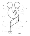
- Fig. 1 schematically shows an exemplifying embodiment of the invention in which one winding roll 12 is used.
- a web is guided for example from an unwinding station (not shown) in between slitter blades 13, 14 or laser or water jet slitting means which slit the web W in the longitudinal direction into partial webs W1, W2.
- W1 are indicated those partial webs that will be guided from the guide roll 15 via another guide roll 31 to the first winding station 21 to be wound into first partial web rolls R1
- reference sign are indicated those partial webs that will be guided from the guide roll 15 via another guide roll 32 to second winding station to be wound into second partial web rolls R2.
- the partial webs W1, W2 are wound into partial web rolls R1, R2 via the winding roll 12 on respective winding station 21, 22.
- Each partial web roll is created around a core or equivalent winding spool.
- Substantially all partial webs W1, W2 pass via the first guide roll 15 and every second partial webs W1 are guided to the guide roll 31 and the winding up thus occurs via winding roll 12 at the first winding stations 21.
- From the guide roll 15 the other every second partial webs W2 are guided via guide roll 32 to be wound up via winding roll 12 on second winding stations 22.
- the wrap angle that the partial webs are on the surface of the winding roll, in the figure between lines A1, A2, respectively for each winding station 21, 22 is at least 120 ° and the wrap angle relation, i.e. relation of the larger wrap angle to the smaller wrap angle is at least 1 and at most 1,25.
- Fig. 2 schematically shows an exemplifying embodiment of the invention in which two winding rolls 41, 42 are used.
- a web W is guided for example from an unwinding station 10 in between slitter blades 13, 14 or laser or water jet slitting means which slit the web W in the longitudinal direction into partial webs W1, W2.
- W1 are indicated those partial webs that will be guided from the guide roll 15 to the first winding station 21 to be wound into first partial web rolls R1
- reference sign are indicated those partial webs that will be guided from the guide roll 15 to second winding station to be wound into second partial web rolls R2.
- the partial webs W1, W2 are wound into partial web rolls R1, R2 via the winding rolls 41, 42 on respective winding station 21, 22.
- Each partial web roll is created around a core or equivalent winding spool. Substantially all partial webs W1, W2 pass via the first guide roll 15 and every second partial webs W1 are guided to the winding roll 41 of the first winding station 21 and the winding up thus occurs via winding roll 12 at the first winding stations 21. From the guide roll 15 the other every second partial webs W2 are guided to be wound up via the second winding roll 42 on second winding stations 22.
- the wrap angle that the partial webs are on the surface of the winding roll, in the figure between lines A1, A2, respectively for each winding station 21, 22 is at least 120 ° and the wrap angle relation, i.e. relation of the larger wrap angle to the smaller wrap angle is at least 1 and at most 1,25.
- Fig. 3 schematically shows an example of a winding station 21; 22 supported on the floor 52.
- the figure shows a winding roll 12, partial webs guidable to which are designated with reference W1; W2.
- the partial webs W1, W2 are wound into partial web rolls R1; R2 via the winding roll 12 on a winding station 21; 22.
- the winding station 21; 22 is supported on a floor 52 or equivalent foundation, and the web roll R1; R2 is attached to the winding station linearly movably via a support arm 51 or equivalent.
- the web roll is created around a core 25 or equivalent winding spool which is connected from its centre to the support arm 51.
- the growing web roll moves linearly at a certain angle B in relation to the winding roll 12, which is shown in Fig. 1 by an arrow S.
- the support angle B of the roll is larger than 0 degrees and smaller than or equal to 90 degrees, most advantageously 45-90 degrees.
- the winding up of partial webs W1; W2 into partial web rolls R1; R2 occurs utilising the mass of the partial web roll as the partial web roll supports itself advantageously at least of its partial mass on the winding roll 12 below.
- the mass of the partial web roll advantageously provides the nip load required for winding between the web roll and the roll.
- the other part of the mass of the web roll is supported by winding chucks of the support arm 51 from the centre of the web roll from the core 25.
- the winding stations 21; 22 according to Fig. 3 are advantageously positioned in connection with the winding roll 12 in the example of figure 1 and in connection with both winding rolls 41, 42 in the example of figure 2 .
- the winding station 22 in connection with the second winding roll 42 is substantially a mirror image in relation to the winding station 21 being in connection with the first winding roll 41.
Description
- The invention relates to a method according to the preamble of claim 1 for winding fiber webs, particularly paper and board webs, into partial web rolls, , in which method, partial web rolls are wound via a nip between a winding roll and the roll being formed on a winding station formed into connection with the winding roll.
- The invention also relates to a device according to the preamble of claim 6 for winding fiber webs, particularly paper and board webs, into partial web rolls, which device includes winding stations for winding partial web rolls via a nip between a winding roll and the roll being formed.
- It is known that a fiber web, e.g. paper, is manufactured in machines which together constitute a paper-manufacturing line which can be hundreds of metres long. Modern paper machines can produce over 450,000 tons of paper per year. The speed of the paper machine can exceed 2,000 m/min and the width of the paper web can be more than 11 metres.
- In paper-manufacturing lines, the manufacture of paper takes place as a continuous process. A paper web completing in the paper machine is reeled by a reel-up around a reeling shaft i.e. a reel spool into a parent roll the diameter of which can be more than 5 metres and the weight more than 160 tons. The purpose of reeling is to modify the paper web manufactured as planar to a more easily processable form. On the reel-up located in the main machine line, the continuous process of the paper machine breaks for the first time and shifts into periodic operation.
- The web of parent roll produced in paper manufacture is full-width and even more than 100 km long so it must be slit into partial webs with suitable width and length for the customers of the paper mill and wound around cores into so-called customer rolls before delivering them from the paper mill. This slitting and winding up of the web takes place as known in an appropriate separate machine i.e. a slitter-winder.
- On the slitter-winder, the parent roll is unwound, the wide web is slit on the slitting section into several narrower partial webs which are wound up on the winding section around winding cores, such as spools, into customer rolls. When the customer rolls are completed, the slitter-winder is stopped and the rolls i.e. the so-called set is removed from the machine. Then, the process is continued with the winding of a new set. These steps are repeated periodically until paper runs out of the parent roll, whereby a parent roll change is performed and the operation starts again as the unwinding of a new parent roll.
- Slitter-winders employ winding devices of different types depending on, inter alia, on the type of the fiber web being wound. On slitter-winders of the multistation winder type, the web is guided from the unwinding via guide rolls to the slitting section where the web is slit into partial webs which are further guided to the winding roll/rolls on the winding stations into customer rolls to be wound up onto cores. Adjacent partial webs are wound up on different sides of the winding roll/rolls. Multistation winders have one to three winding rolls and in them each partial web is wound to a partial web roll in its own winding station. During winding a winding nip is formed between the winding roll and the partial web roll to be wound. The winding nip tightens the web in the nip and at a wrap area that is the area the web runs on the surface of the winding roll. The tightening increases when the winding roll has a soft coating. If the length of the wrap is not long enough, the web will slide on the surface of the winding roll. In case partial webs next to each other have wrap of different length the result is a difference of tension of partial webs, which causes runnability problems and differences in tightness of the partial web rolls. Attempts have been made in prior art to solve this by using a tension interruption roll at the winding roll but they have proven unreliable and they also require a lot of maintenance.
- Thus when winding up webs on winding stations, it is important that the web stays fast without sliding on the surface of the winding roll when entering the winding nip of the winding station, whereby the tension of the entering web remains in control. If/when sliding in practice occurs, it is important that possible circumferential distances of different lengths of the partial webs i.e. wrap angles of different sizes on the periphery of the winding roll are either eliminated or, if this is not possible, tension differences of the partial webs caused by the surrounding distances of different lengths one may try to compensate by means of the winding technique using different winding parameters. If sliding on different winding stations is different, the partial web rolls are formed different of their hardness.
- On some slitters of the multistation winder type known of prior art, the winding up of partial webs occurs on both sides of one winding roll, having the diameter of typically 1,200 mm or 1,500 mm. For instance, specification
EP0478719 describes a known winder of a slitter-winder where the winding up of partial webs occurs on both sides of the winding roll and the circumferential distances of partial webs are different on the winding stations positioned on different sides of the winding roll. As a solution for this, patent specificationEP0478719 describes the use of a separate so-called tension interruption roll. By the tension interruption roll, the partial webs are locked onto the surface of the winding roll thus aiming to eliminate the effect of sliding. When the web tension provided by the unwinding device is this way interrupted before winding up, the winding up requires additional devices, e.g. centre drives of winding stations, which then again provide the web with tension required for winding up. Such a method is not cost-effective in terms of power consumption. - On some other multistation winder types known of prior art, the so-called three-roll winders, which are described e.g. by patent specification F171708 (
US4601345 ) and patent specificationUS4508283 , the winding up of partial webs occurs by means of two winding rolls, typically having the diameter of 850 mm or 1,000 mm, and a guide roll positioned between them. Partial webs are guided separate from each other before guiding to the winding rolls. F171708 describes a winder of a slitter-winder where winding arms are pivoted whereby, as the roll diameter increases, the winding nip transfers on the periphery of the winding roll, i.e. the wrap angle of the web on the winding roll changes.US4508283 describes winders of a slitter-winder where the winding stations are above the winding roll and suspended on a robust cross beam in the cross-machine direction and their support requires massive structures above the winding roll. In these kinds of winders, the roll surrounding distances of partial webs guided on different sides of the winder are optimised such that the distances on the periphery of the winding rolls and the periphery of the guide roll are substantially the same on the winding stations on both sides of the slitter-winder. To ensure uniform winding, the winding rolls and the guide roll are mechanically connected together and this group is driven by one electric motor. The partial web rolls to be wound are supported by arms that move the web roll in relation to the winding roll as the diameter of the partial web roll increases during winding. These kinds of arrangements prerequisites a tight mutual diameter tolerance in the manufacture of winding and guide rolls and support arms of the web rolls, thus making the manufacture of winder require high precision. - In
US patent 2460694 is disclosed a prior art winder with two winding rolls in this arrangement the partial web rolls to be wound are supported by arms that move the web roll in relation to the winding roll as the diameter of the partial web roll increases during winding and thus the wrap angle changes during winding whereby, as the roll diameter increases, the winding nip transfers on the periphery of the winding roll, i.e. the wrap angle of the web on the winding roll changes. - In
EP patent application 1657193 is disclosed a prior art winder for continuous winding with two winding equipment each with two winding stations. In this known winding arrangement the wrap angle changes depending on the partial web roll to be wound and its winding station. - An object of the invention is to create a device and a method for winding fiber webs where the problems relating to sliding of the partial webs on winding roll/winding rolls have been eliminated or at least minimized.
- An object of the invention is to create a device and a method for winding fiber webs where the problems due to the tension differences of the partial webs on winding roll/winding rolls have been eliminated or at least minimized.
- An object of the invention is to provide a device and a method for winding fiber webs where the result of the winding is the best possible and similar in all simultaneously wound partial web rolls.
- To achieve the above-mentioned objects and those which come out later, the method according to the invention is mainly characterised by what is presented in the characterising part of claim 1. The device according to the invention is mainly characterised by what is presented in the characterising part of claim 6.
- According to the invention a method and a device for winding of partial webs a multistation winder type with one winding roll or advantageously with two winding rolls is used where the wrap angle on each winding roll is respectively for each winding station at least 120 ° and wrap angle relation, i.e. relation of the larger wrap angle to the smaller wrap angle is at least 1 and at most 1, 25. This provides that in sliding situation partial webs on winding roll / winding rolls behave in a similar manner and thus sliding does not create problems in winding in different winding stations.
- By the invention in the winding the large wrap angle in combination to the wrap angle relation of 1 - 1, 25 results that sliding problems are minimized and the tension of the partial webs directed to different winding stations provides for good runnability and simultaneously partial web rolls to be wound will be free of tightness problems. The invention also provides for large range of available running parameters due to the solved sliding problems.
- According to advantageous feature of the invention, winding up occurs utilising the mass of the roll and, as the roll diameter increases, its centre moves linearly at a certain angle in relation to the winding roll, whereby the position of the nip remains stationary. The winding stations are sturdily supported on the machine level floor or equivalent foundation.
- According to an advantageous additional characteristic of the invention, the winding stations are directly supported on the floor, thus providing them an extremely good and stable support without massive support structures above the machine floor level.
- Next, the invention will be described in more detail with reference to the figures of the enclosed drawing, to the details of which the invention is intended by no means to be narrowly limited.
-
Fig. 1 schematically shows an exemplifying embodiment of the invention in which one winding roll is used, -
Fig. 2 schematically shows an exemplifying embodiment of the invention in which two winding rolls are used and -
Fig. 3 schematically shows an example of a winding station supported on a floor. -
Fig. 1 schematically shows an exemplifying embodiment of the invention in which onewinding roll 12 is used. A web is guided for example from an unwinding station (not shown) in betweenslitter blades guide roll 15 via anotherguide roll 31 to thefirst winding station 21 to be wound into first partial web rolls R1 and by reference sign are indicated those partial webs that will be guided from theguide roll 15 via anotherguide roll 32 to second winding station to be wound into second partial web rolls R2. The partial webs W1, W2 are wound into partial web rolls R1, R2 via thewinding roll 12 onrespective winding station first guide roll 15 and every second partial webs W1 are guided to theguide roll 31 and the winding up thus occurs via windingroll 12 at the first windingstations 21. From theguide roll 15 the other every second partial webs W2 are guided viaguide roll 32 to be wound up via windingroll 12 on second windingstations 22. The wrap angle that the partial webs are on the surface of the winding roll, in the figure between lines A1, A2, respectively for each windingstation -
Fig. 2 schematically shows an exemplifying embodiment of the invention in which two windingrolls station 10 in betweenslitter blades guide roll 15 to the first windingstation 21 to be wound into first partial web rolls R1 and by reference sign are indicated those partial webs that will be guided from theguide roll 15 to second winding station to be wound into second partial web rolls R2. The partial webs W1, W2 are wound into partial web rolls R1, R2 via the winding rolls 41, 42 on respective windingstation first guide roll 15 and every second partial webs W1 are guided to the windingroll 41 of the first windingstation 21 and the winding up thus occurs via windingroll 12 at the first windingstations 21. From theguide roll 15 the other every second partial webs W2 are guided to be wound up via the second windingroll 42 on second windingstations 22. The wrap angle that the partial webs are on the surface of the winding roll, in the figure between lines A1, A2, respectively for each windingstation -
Fig. 3 schematically shows an example of a windingstation 21; 22 supported on thefloor 52. The figure shows a windingroll 12, partial webs guidable to which are designated with reference W1; W2. The partial webs W1, W2 are wound into partial web rolls R1; R2 via the windingroll 12 on a windingstation 21; 22. The windingstation 21; 22 is supported on afloor 52 or equivalent foundation, and the web roll R1; R2 is attached to the winding station linearly movably via asupport arm 51 or equivalent. The web roll is created around acore 25 or equivalent winding spool which is connected from its centre to thesupport arm 51. As the web roll diameter increases when the winding proceeds, the growing web roll moves linearly at a certain angle B in relation to the windingroll 12, which is shown inFig. 1 by an arrow S. The support angle B of the roll is larger than 0 degrees and smaller than or equal to 90 degrees, most advantageously 45-90 degrees. When the web rolls R1; R2 are completed, it is easy to release them from the windingstation 21; 22 and to deliver the set i.e. to remove the completed partial web rolls R1; R2 from the windingroll 12, because the windingstation 21; 22 is supported on thefloor 52 or equivalent foundation structure, whereby the periphery of the web roll is positioned close to the level of thefloor 52. The winding up of partial webs W1; W2 into partial web rolls R1; R2 occurs utilising the mass of the partial web roll as the partial web roll supports itself advantageously at least of its partial mass on the windingroll 12 below. Hence, the mass of the partial web roll advantageously provides the nip load required for winding between the web roll and the roll. The other part of the mass of the web roll is supported by winding chucks of thesupport arm 51 from the centre of the web roll from thecore 25. - The winding
stations 21; 22 according toFig. 3 are advantageously positioned in connection with the windingroll 12 in the example offigure 1 and in connection with both windingrolls figure 2 . In connection with the example offigure 2 , naturally, the windingstation 22 in connection with the second windingroll 42 is substantially a mirror image in relation to the windingstation 21 being in connection with the first windingroll 41.
Claims (9)
- A method for winding fiber webs, particularly paper and board webs, in which method, partial web rolls (R1, R2) are wound in a winding device that comprises at least two winding stations (21, 22), where partial webs (W1, W2) are guided to rolls (R1, R2) via a nip between a winding roll (12; 41,42) and the rolls (R1, R2), in which method partial webs (W1, W2) are guided on the surface of the winding roll (12; 41, 42) before entering the nip creating a wrap angle (A1, A2), characterised in, that in the method the wrap angle (A1, A2) that the partial webs are guided on the surface of the winding roll (12; 41,42) is respectively for each winding station (21, 22) at least 120 °and the wrap angle relation, i.e. relation of the larger wrap angle to the smaller wrap angle is at least 1 and at most 1,25.
- A method according to claim 1, characterised by, in the method the winding stations (21, 22) are formed in connection with one winding roll (12).
- A method according to claim 2, characterised by, in the method the web (W) is guided from an unwinding station in between slitter blades (13, 14) which slit the web (W) in the longitudinal direction into the partial webs (W1, W2) and the partial webs (W1, W2) are guided via first guide roll (15) and every second partial webs (W1) are guided to a second guide roll (31) and the winding up via a winding roll (12) at the first winding stations (21) and the other every second partial webs (W2) are guided via another second guide roll (32) to be wound up via winding roll (12) on the second winding stations (22).
- A method according to claim 1, characterised by, in the method the winding stations (21, 22) are formed by two winding rolls (41, 42).
- A method according to claim 4, characterised by, in the method the web (W) is guided from an unwinding station (10) in between slitter blades (13, 14) which slit the web (W) in the longitudinal direction into partial webs (W1, W2) and the partial webs (W1, W2) are guided via a first guide roll (15) and every second partial webs (W1) are guided to the winding roll (41) of the first winding station (21) and from the guide roll (15) the other every second partial webs (W2) are guided to the second winding roll (42) of the second winding stations (22) and the partial webs (W1, W2) are wound into partial web rolls (R1, R2) via the winding rolls (41, 42) on respective winding station (21, 22).
- A device for winding fiber webs, particularly paper and board webs, which device comprises at least one winding roll (12; 41, 42) for winding partial webs (W1, W2) into partial web rolls (R1, R2) via a nip between the winding roll (12; 41, 42) and the roll being formed (R1, R2), which device comprises means for guiding the partial webs on the surface of the winding roll (12, 41, 42) for creating a wrap angle, characterised in that in the device the means for creating the wrap angle are located such that the wrap angle (A1, A2) that the partial webs are guided on the surface of the winding roll (12; 41,42) is respectively for each winding station (21, 22) at least 120 °an d the wrap angle relation, i.e. relation of the larger wrap angle to the smaller wrap angle is at least 1 and at most 1,25.
- A device according to claim 6, characterised in that the device comprises an unwinder for unwinding a full-width web (W) and slitting means (13, 14) for slitting the full-width web (W) into partial webs (W1, W2), that the device further comprises guide rolls (15, 31, 32) for guiding the slitted partial webs (W1, W2) to the at least one winding roll (12), where there are at least two winding stations (21, 22) for winding partial web rolls (R1, R2).
- A device according to claim 6, characterised in that the device comprises an unwinder (10) for unwinding a full-width web (W) and slitting means (13, 14)for slitting the full-width web (W) into partial webs (W1, W2), that the device further comprises a guide roll (15) for guiding the slitted partial webs (W1, W2) to the two winding rolls (41, 42) forming at least two winding stations (21, 22) for winding partial web rolls (R1, R2).
- A device according to claim 6, characterised in that in the device at least one winding station (21; 22) is supported on a floor (52) or equivalent foundation.
Priority Applications (4)
| Application Number | Priority Date | Filing Date | Title |
|---|---|---|---|
| EP12164212.8A EP2653421B1 (en) | 2012-04-16 | 2012-04-16 | Method and device for winding of fiber webs, especially of paper and board webs |
| CA2803426A CA2803426C (en) | 2012-04-16 | 2013-01-30 | Method and device for winding of fiber webs, especially of paper and board webs |
| US13/862,998 US9169095B2 (en) | 2012-04-16 | 2013-04-15 | Method and device for winding of fiber webs, especially of paper and board webs |
| CN201310130593.9A CN103373628B (en) | 2012-04-16 | 2013-04-16 | For the method and apparatus of coiled fiber web especially paper web and board web |
Applications Claiming Priority (1)
| Application Number | Priority Date | Filing Date | Title |
|---|---|---|---|
| EP12164212.8A EP2653421B1 (en) | 2012-04-16 | 2012-04-16 | Method and device for winding of fiber webs, especially of paper and board webs |
Publications (2)
| Publication Number | Publication Date |
|---|---|
| EP2653421A1 EP2653421A1 (en) | 2013-10-23 |
| EP2653421B1 true EP2653421B1 (en) | 2015-04-15 |
Family
ID=46027650
Family Applications (1)
| Application Number | Title | Priority Date | Filing Date |
|---|---|---|---|
| EP12164212.8A Active EP2653421B1 (en) | 2012-04-16 | 2012-04-16 | Method and device for winding of fiber webs, especially of paper and board webs |
Country Status (4)
| Country | Link |
|---|---|
| US (1) | US9169095B2 (en) |
| EP (1) | EP2653421B1 (en) |
| CN (1) | CN103373628B (en) |
| CA (1) | CA2803426C (en) |
Families Citing this family (3)
| Publication number | Priority date | Publication date | Assignee | Title |
|---|---|---|---|---|
| EP2653421B1 (en) | 2012-04-16 | 2015-04-15 | Valmet Technologies, Inc. | Method and device for winding of fiber webs, especially of paper and board webs |
| DE102019127670A1 (en) * | 2019-10-15 | 2021-04-15 | Voith Patent Gmbh | Process for the production of finished rolls of fibrous web |
| CN114084723B (en) * | 2021-12-01 | 2023-12-19 | 安徽中星新材料股份有限公司 | Rewinding process of environment-friendly winding film |
Family Cites Families (30)
| Publication number | Priority date | Publication date | Assignee | Title |
|---|---|---|---|---|
| US2460694A (en) | 1945-08-08 | 1949-02-01 | Ecusta Paper Corp | Web tensioning and pressure mechanism |
| FR1238323A (en) | 1959-06-29 | 1960-08-12 | Etudes De Machines Speciales | Automatic rewinding device |
| DE1276584C2 (en) | 1965-01-20 | 1978-12-14 | Trockentechnik Kurt Brückner KG, 7250 Leonberg | DEVICE FOR CONTINUOUS WINDING OF A FLAT-SHAPED PRODUCT ROLL |
| FI52561C (en) | 1970-12-10 | 1987-03-18 | Jagenberg Werke Ag | FOERFARANDE OCH ANORDNING FOER AXELLOES UPPRULLNING AV I BANOR FOERELIGGANDE MATERIAL. |
| DE2633408C2 (en) | 1976-07-24 | 1978-06-15 | Jagenberg-Werke Ag, 4000 Duesseldorf | Pressure roller arrangement in a winding machine for webs of material to be wound |
| US4394990A (en) * | 1980-12-19 | 1983-07-26 | Eastman Kodak Company | Web cinching and winding apparatus and method |
| DE3102894C2 (en) | 1981-01-29 | 1983-01-20 | Jagenberg-Werke AG, 4000 Düsseldorf | Device for the separate winding of lengthways divided webs |
| US4440356A (en) | 1981-07-23 | 1984-04-03 | Erwin Kampf Gmbh & Co. | Machine for separating and slitting thin sheet |
| DE3243994C2 (en) | 1982-11-27 | 1986-07-10 | J.M. Voith Gmbh, 7920 Heidenheim | Winding machine for winding a lengthwise split web |
| FI71708C (en) * | 1983-07-07 | 1992-03-23 | Valmet Paper Machinery Inc | reeling device |
| US4601345A (en) | 1985-06-10 | 1986-07-22 | Mahrt David M | Mixing and drop system for fire retardants |
| FI100099B (en) * | 1988-11-17 | 1997-09-30 | Valmet Paper Machinery Inc | Method and apparatus for winding a paper web |
| DE4012979A1 (en) | 1990-04-24 | 1991-11-07 | Jagenberg Ag | METHOD AND DEVICE FOR WINDING MATERIAL SHEETS, ESPECIALLY PAPER OR CARDBOARD SHEETS |
| FI932674A (en) | 1992-06-13 | 1993-12-14 | Jagenberg Ag | ROLLER MASK FOR ROLLING AV EN PAPPERS- ELLER CARTON |
| DE9317616U1 (en) * | 1993-11-19 | 1995-03-16 | Beloit Technologies Inc | Winding machine |
| FI100467B (en) | 1994-05-26 | 1997-12-15 | Valmet Corp | Method and apparatus for web rolling |
| DE4424848A1 (en) | 1994-07-14 | 1996-01-18 | Jagenberg Papiertech Gmbh | Winding machine e.g. for winding paper or card strips onto core rolls |
| FI105464B (en) * | 1996-06-10 | 2000-08-31 | Valmet Corp | Method and device for winding |
| FI101371B1 (en) | 1996-07-05 | 1998-06-15 | Valmet Corp | Method of paper web winding and winding device |
| ES2169435T3 (en) * | 1996-09-04 | 2002-07-01 | Jagenberg Papiertech Gmbh | PROCEDURE AND WINDING MACHINE FOR THE WRAPPING OF PAPER OR CARTON BANDS. |
| DE19649354B4 (en) | 1996-11-28 | 2005-11-03 | Voith Paper Patent Gmbh | Winding machine for paper or board webs |
| DE19716887A1 (en) | 1997-04-22 | 1998-10-29 | Voith Sulzer Papiermasch Gmbh | Winding machine |
| FI102604B (en) * | 1997-06-03 | 1999-01-15 | Valmet Corp | Device for winding the web |
| DE19734829C2 (en) | 1997-08-12 | 2002-01-31 | Voith Paper Gmbh | winder |
| JP2002220139A (en) * | 2001-01-24 | 2002-08-06 | Fuji Iron Works Co Ltd | Slitter device |
| FI114209B (en) * | 2002-06-14 | 2004-09-15 | Metso Paper Inc | Method for controlling the structure of a fiber web roller e.g. a paper or cardboard roll |
| DE102004054988A1 (en) * | 2004-11-13 | 2006-05-18 | Voith Paper Patent Gmbh | Roll winding device and method for producing winding rolls |
| FI123533B (en) | 2010-10-29 | 2013-06-28 | Metso Paper Inc | Apparatus for winding fibrous webs, in particular paper and board |
| EP2653421B1 (en) | 2012-04-16 | 2015-04-15 | Valmet Technologies, Inc. | Method and device for winding of fiber webs, especially of paper and board webs |
| EP2653422B1 (en) | 2012-04-20 | 2015-06-03 | Valmet Technologies, Inc. | Method and device for winding of fiber webs, especially of partial paper and board webs |
-
2012
- 2012-04-16 EP EP12164212.8A patent/EP2653421B1/en active Active
-
2013
- 2013-01-30 CA CA2803426A patent/CA2803426C/en active Active
- 2013-04-15 US US13/862,998 patent/US9169095B2/en active Active
- 2013-04-16 CN CN201310130593.9A patent/CN103373628B/en active Active
Also Published As
| Publication number | Publication date |
|---|---|
| CA2803426C (en) | 2020-02-25 |
| US9169095B2 (en) | 2015-10-27 |
| US20130270383A1 (en) | 2013-10-17 |
| CA2803426A1 (en) | 2013-10-16 |
| CN103373628B (en) | 2016-04-27 |
| EP2653421A1 (en) | 2013-10-23 |
| CN103373628A (en) | 2013-10-30 |
Similar Documents
| Publication | Publication Date | Title |
|---|---|---|
| EP2703326B1 (en) | Method for separating partial webs in a slitter winder | |
| EP2653422B1 (en) | Method and device for winding of fiber webs, especially of partial paper and board webs | |
| EP2653421B1 (en) | Method and device for winding of fiber webs, especially of paper and board webs | |
| EP3643654A1 (en) | Method of operating an off-line finishing device for fiber webs, in particular an off-line slitter-winder for winding fiber webs | |
| EP2666739B1 (en) | Method of applying adhesive in a slitter-winder of fiber web machine | |
| EP2522608B1 (en) | Device for applying adhesive in a slitter-winder of fiber web machine | |
| EP2540649B1 (en) | Method and arrangement in connection with an unwinder | |
| US20130240658A1 (en) | Device for winding of fiber webs, especially of paper and board webs | |
| EP2495195B1 (en) | Arrangement in handling web rolls | |
| EP2084091B1 (en) | Fibre-web machine slitter-winder | |
| WO2012056095A1 (en) | Method and device for winding of fiber webs, especially of paper and board webs | |
| US11332335B2 (en) | Reeling shaft transfer rail system and method of transferring reeling shafts on a reeling shaft transfer rail system | |
| EP2543616B1 (en) | Arrangement in a slitter-winder for a fiber web machine | |
| FI129160B (en) | Rereeler and method for rereeling fiber webs | |
| EP2664567B1 (en) | Method for web threading in a slitter-winder and a slitter-winder |
Legal Events
| Date | Code | Title | Description |
|---|---|---|---|
| PUAI | Public reference made under article 153(3) epc to a published international application that has entered the european phase |
Free format text: ORIGINAL CODE: 0009012 |
|
| 17P | Request for examination filed |
Effective date: 20120918 |
|
| AK | Designated contracting states |
Kind code of ref document: A1 Designated state(s): AL AT BE BG CH CY CZ DE DK EE ES FI FR GB GR HR HU IE IS IT LI LT LU LV MC MK MT NL NO PL PT RO RS SE SI SK SM TR |
|
| AX | Request for extension of the european patent |
Extension state: BA ME |
|
| RAP1 | Party data changed (applicant data changed or rights of an application transferred) |
Owner name: VALMET TECHNOLOGIES, INC. |
|
| REG | Reference to a national code |
Ref country code: DE Ref legal event code: R079 Ref document number: 602012006631 Country of ref document: DE Free format text: PREVIOUS MAIN CLASS: B65H0018160000 Ipc: B65H0018080000 |
|
| RIC1 | Information provided on ipc code assigned before grant |
Ipc: B65H 18/16 20060101ALI20141009BHEP Ipc: B65H 18/26 20060101ALI20141009BHEP Ipc: B65H 18/08 20060101AFI20141009BHEP |
|
| GRAP | Despatch of communication of intention to grant a patent |
Free format text: ORIGINAL CODE: EPIDOSNIGR1 |
|
| INTG | Intention to grant announced |
Effective date: 20141125 |
|
| GRAS | Grant fee paid |
Free format text: ORIGINAL CODE: EPIDOSNIGR3 |
|
| GRAA | (expected) grant |
Free format text: ORIGINAL CODE: 0009210 |
|
| AK | Designated contracting states |
Kind code of ref document: B1 Designated state(s): AL AT BE BG CH CY CZ DE DK EE ES FI FR GB GR HR HU IE IS IT LI LT LU LV MC MK MT NL NO PL PT RO RS SE SI SK SM TR |
|
| REG | Reference to a national code |
Ref country code: GB Ref legal event code: FG4D Ref country code: CH Ref legal event code: EP |
|
| REG | Reference to a national code |
Ref country code: IE Ref legal event code: FG4D |
|
| REG | Reference to a national code |
Ref country code: AT Ref legal event code: REF Ref document number: 721823 Country of ref document: AT Kind code of ref document: T Effective date: 20150515 |
|
| REG | Reference to a national code |
Ref country code: DE Ref legal event code: R096 Ref document number: 602012006631 Country of ref document: DE Effective date: 20150528 |
|
| REG | Reference to a national code |
Ref country code: NL Ref legal event code: VDEP Effective date: 20150415 |
|
| REG | Reference to a national code |
Ref country code: LT Ref legal event code: MG4D |
|
| PG25 | Lapsed in a contracting state [announced via postgrant information from national office to epo] |
Ref country code: NL Free format text: LAPSE BECAUSE OF FAILURE TO SUBMIT A TRANSLATION OF THE DESCRIPTION OR TO PAY THE FEE WITHIN THE PRESCRIBED TIME-LIMIT Effective date: 20150415 |
|
| PG25 | Lapsed in a contracting state [announced via postgrant information from national office to epo] |
Ref country code: NO Free format text: LAPSE BECAUSE OF FAILURE TO SUBMIT A TRANSLATION OF THE DESCRIPTION OR TO PAY THE FEE WITHIN THE PRESCRIBED TIME-LIMIT Effective date: 20150715 Ref country code: PT Free format text: LAPSE BECAUSE OF FAILURE TO SUBMIT A TRANSLATION OF THE DESCRIPTION OR TO PAY THE FEE WITHIN THE PRESCRIBED TIME-LIMIT Effective date: 20150817 Ref country code: HR Free format text: LAPSE BECAUSE OF FAILURE TO SUBMIT A TRANSLATION OF THE DESCRIPTION OR TO PAY THE FEE WITHIN THE PRESCRIBED TIME-LIMIT Effective date: 20150415 Ref country code: FI Free format text: LAPSE BECAUSE OF FAILURE TO SUBMIT A TRANSLATION OF THE DESCRIPTION OR TO PAY THE FEE WITHIN THE PRESCRIBED TIME-LIMIT Effective date: 20150415 Ref country code: ES Free format text: LAPSE BECAUSE OF FAILURE TO SUBMIT A TRANSLATION OF THE DESCRIPTION OR TO PAY THE FEE WITHIN THE PRESCRIBED TIME-LIMIT Effective date: 20150415 Ref country code: LT Free format text: LAPSE BECAUSE OF FAILURE TO SUBMIT A TRANSLATION OF THE DESCRIPTION OR TO PAY THE FEE WITHIN THE PRESCRIBED TIME-LIMIT Effective date: 20150415 |
|
| PG25 | Lapsed in a contracting state [announced via postgrant information from national office to epo] |
Ref country code: LV Free format text: LAPSE BECAUSE OF FAILURE TO SUBMIT A TRANSLATION OF THE DESCRIPTION OR TO PAY THE FEE WITHIN THE PRESCRIBED TIME-LIMIT Effective date: 20150415 Ref country code: IS Free format text: LAPSE BECAUSE OF FAILURE TO SUBMIT A TRANSLATION OF THE DESCRIPTION OR TO PAY THE FEE WITHIN THE PRESCRIBED TIME-LIMIT Effective date: 20150815 Ref country code: RS Free format text: LAPSE BECAUSE OF FAILURE TO SUBMIT A TRANSLATION OF THE DESCRIPTION OR TO PAY THE FEE WITHIN THE PRESCRIBED TIME-LIMIT Effective date: 20150415 Ref country code: GR Free format text: LAPSE BECAUSE OF FAILURE TO SUBMIT A TRANSLATION OF THE DESCRIPTION OR TO PAY THE FEE WITHIN THE PRESCRIBED TIME-LIMIT Effective date: 20150716 |
|
| REG | Reference to a national code |
Ref country code: CH Ref legal event code: PL |
|
| REG | Reference to a national code |
Ref country code: DE Ref legal event code: R097 Ref document number: 602012006631 Country of ref document: DE |
|
| REG | Reference to a national code |
Ref country code: IE Ref legal event code: MM4A |
|
| PG25 | Lapsed in a contracting state [announced via postgrant information from national office to epo] |
Ref country code: MC Free format text: LAPSE BECAUSE OF FAILURE TO SUBMIT A TRANSLATION OF THE DESCRIPTION OR TO PAY THE FEE WITHIN THE PRESCRIBED TIME-LIMIT Effective date: 20150415 Ref country code: CH Free format text: LAPSE BECAUSE OF NON-PAYMENT OF DUE FEES Effective date: 20150430 Ref country code: DK Free format text: LAPSE BECAUSE OF FAILURE TO SUBMIT A TRANSLATION OF THE DESCRIPTION OR TO PAY THE FEE WITHIN THE PRESCRIBED TIME-LIMIT Effective date: 20150415 Ref country code: LI Free format text: LAPSE BECAUSE OF NON-PAYMENT OF DUE FEES Effective date: 20150430 Ref country code: EE Free format text: LAPSE BECAUSE OF FAILURE TO SUBMIT A TRANSLATION OF THE DESCRIPTION OR TO PAY THE FEE WITHIN THE PRESCRIBED TIME-LIMIT Effective date: 20150415 |
|
| PLBE | No opposition filed within time limit |
Free format text: ORIGINAL CODE: 0009261 |
|
| STAA | Information on the status of an ep patent application or granted ep patent |
Free format text: STATUS: NO OPPOSITION FILED WITHIN TIME LIMIT |
|
| PG25 | Lapsed in a contracting state [announced via postgrant information from national office to epo] |
Ref country code: CZ Free format text: LAPSE BECAUSE OF FAILURE TO SUBMIT A TRANSLATION OF THE DESCRIPTION OR TO PAY THE FEE WITHIN THE PRESCRIBED TIME-LIMIT Effective date: 20150415 Ref country code: PL Free format text: LAPSE BECAUSE OF FAILURE TO SUBMIT A TRANSLATION OF THE DESCRIPTION OR TO PAY THE FEE WITHIN THE PRESCRIBED TIME-LIMIT Effective date: 20150415 Ref country code: RO Free format text: LAPSE BECAUSE OF NON-PAYMENT OF DUE FEES Effective date: 20150415 Ref country code: SK Free format text: LAPSE BECAUSE OF FAILURE TO SUBMIT A TRANSLATION OF THE DESCRIPTION OR TO PAY THE FEE WITHIN THE PRESCRIBED TIME-LIMIT Effective date: 20150415 |
|
| REG | Reference to a national code |
Ref country code: FR Ref legal event code: ST Effective date: 20160205 |
|
| 26N | No opposition filed |
Effective date: 20160118 |
|
| PG25 | Lapsed in a contracting state [announced via postgrant information from national office to epo] |
Ref country code: IE Free format text: LAPSE BECAUSE OF NON-PAYMENT OF DUE FEES Effective date: 20150416 |
|
| PG25 | Lapsed in a contracting state [announced via postgrant information from national office to epo] |
Ref country code: FR Free format text: LAPSE BECAUSE OF NON-PAYMENT OF DUE FEES Effective date: 20150615 Ref country code: SI Free format text: LAPSE BECAUSE OF FAILURE TO SUBMIT A TRANSLATION OF THE DESCRIPTION OR TO PAY THE FEE WITHIN THE PRESCRIBED TIME-LIMIT Effective date: 20150415 |
|
| PG25 | Lapsed in a contracting state [announced via postgrant information from national office to epo] |
Ref country code: BE Free format text: LAPSE BECAUSE OF FAILURE TO SUBMIT A TRANSLATION OF THE DESCRIPTION OR TO PAY THE FEE WITHIN THE PRESCRIBED TIME-LIMIT Effective date: 20150415 |
|
| GBPC | Gb: european patent ceased through non-payment of renewal fee |
Effective date: 20160416 |
|
| PG25 | Lapsed in a contracting state [announced via postgrant information from national office to epo] |
Ref country code: MT Free format text: LAPSE BECAUSE OF FAILURE TO SUBMIT A TRANSLATION OF THE DESCRIPTION OR TO PAY THE FEE WITHIN THE PRESCRIBED TIME-LIMIT Effective date: 20150415 |
|
| PG25 | Lapsed in a contracting state [announced via postgrant information from national office to epo] |
Ref country code: GB Free format text: LAPSE BECAUSE OF NON-PAYMENT OF DUE FEES Effective date: 20160416 |
|
| REG | Reference to a national code |
Ref country code: AT Ref legal event code: UEP Ref document number: 721823 Country of ref document: AT Kind code of ref document: T Effective date: 20150415 |
|
| PG25 | Lapsed in a contracting state [announced via postgrant information from national office to epo] |
Ref country code: HU Free format text: LAPSE BECAUSE OF FAILURE TO SUBMIT A TRANSLATION OF THE DESCRIPTION OR TO PAY THE FEE WITHIN THE PRESCRIBED TIME-LIMIT; INVALID AB INITIO Effective date: 20120416 Ref country code: BG Free format text: LAPSE BECAUSE OF FAILURE TO SUBMIT A TRANSLATION OF THE DESCRIPTION OR TO PAY THE FEE WITHIN THE PRESCRIBED TIME-LIMIT Effective date: 20150415 Ref country code: SM Free format text: LAPSE BECAUSE OF FAILURE TO SUBMIT A TRANSLATION OF THE DESCRIPTION OR TO PAY THE FEE WITHIN THE PRESCRIBED TIME-LIMIT Effective date: 20150415 |
|
| PG25 | Lapsed in a contracting state [announced via postgrant information from national office to epo] |
Ref country code: SE Free format text: LAPSE BECAUSE OF FAILURE TO SUBMIT A TRANSLATION OF THE DESCRIPTION OR TO PAY THE FEE WITHIN THE PRESCRIBED TIME-LIMIT Effective date: 20150415 Ref country code: CY Free format text: LAPSE BECAUSE OF FAILURE TO SUBMIT A TRANSLATION OF THE DESCRIPTION OR TO PAY THE FEE WITHIN THE PRESCRIBED TIME-LIMIT Effective date: 20150415 |
|
| PG25 | Lapsed in a contracting state [announced via postgrant information from national office to epo] |
Ref country code: TR Free format text: LAPSE BECAUSE OF FAILURE TO SUBMIT A TRANSLATION OF THE DESCRIPTION OR TO PAY THE FEE WITHIN THE PRESCRIBED TIME-LIMIT Effective date: 20150415 |
|
| PG25 | Lapsed in a contracting state [announced via postgrant information from national office to epo] |
Ref country code: LU Free format text: LAPSE BECAUSE OF NON-PAYMENT OF DUE FEES Effective date: 20150416 |
|
| PG25 | Lapsed in a contracting state [announced via postgrant information from national office to epo] |
Ref country code: MK Free format text: LAPSE BECAUSE OF FAILURE TO SUBMIT A TRANSLATION OF THE DESCRIPTION OR TO PAY THE FEE WITHIN THE PRESCRIBED TIME-LIMIT Effective date: 20150415 |
|
| PG25 | Lapsed in a contracting state [announced via postgrant information from national office to epo] |
Ref country code: AL Free format text: LAPSE BECAUSE OF FAILURE TO SUBMIT A TRANSLATION OF THE DESCRIPTION OR TO PAY THE FEE WITHIN THE PRESCRIBED TIME-LIMIT Effective date: 20150415 |
|
| PGFP | Annual fee paid to national office [announced via postgrant information from national office to epo] |
Ref country code: IT Payment date: 20230426 Year of fee payment: 12 Ref country code: DE Payment date: 20230420 Year of fee payment: 12 |
|
| PGFP | Annual fee paid to national office [announced via postgrant information from national office to epo] |
Ref country code: AT Payment date: 20230420 Year of fee payment: 12 |