EP2653358B1 - Radwaschmaschine - Google Patents
Radwaschmaschine Download PDFInfo
- Publication number
- EP2653358B1 EP2653358B1 EP13002034.0A EP13002034A EP2653358B1 EP 2653358 B1 EP2653358 B1 EP 2653358B1 EP 13002034 A EP13002034 A EP 13002034A EP 2653358 B1 EP2653358 B1 EP 2653358B1
- Authority
- EP
- European Patent Office
- Prior art keywords
- drying
- machine
- washing
- fitted
- wheel
- Prior art date
- Legal status (The legal status is an assumption and is not a legal conclusion. Google has not performed a legal analysis and makes no representation as to the accuracy of the status listed.)
- Active
Links
Images





Classifications
-
- B—PERFORMING OPERATIONS; TRANSPORTING
- B60—VEHICLES IN GENERAL
- B60S—SERVICING, CLEANING, REPAIRING, SUPPORTING, LIFTING, OR MANOEUVRING OF VEHICLES, NOT OTHERWISE PROVIDED FOR
- B60S3/00—Vehicle cleaning apparatus not integral with vehicles
- B60S3/002—Vehicle drying apparatus
-
- B—PERFORMING OPERATIONS; TRANSPORTING
- B60—VEHICLES IN GENERAL
- B60S—SERVICING, CLEANING, REPAIRING, SUPPORTING, LIFTING, OR MANOEUVRING OF VEHICLES, NOT OTHERWISE PROVIDED FOR
- B60S3/00—Vehicle cleaning apparatus not integral with vehicles
- B60S3/04—Vehicle cleaning apparatus not integral with vehicles for exteriors of land vehicles
-
- B—PERFORMING OPERATIONS; TRANSPORTING
- B60—VEHICLES IN GENERAL
- B60S—SERVICING, CLEANING, REPAIRING, SUPPORTING, LIFTING, OR MANOEUVRING OF VEHICLES, NOT OTHERWISE PROVIDED FOR
- B60S3/00—Vehicle cleaning apparatus not integral with vehicles
- B60S3/04—Vehicle cleaning apparatus not integral with vehicles for exteriors of land vehicles
- B60S3/042—Wheel cleaning devices
Definitions
- the invention relates to a wheel washing machine, which is generally designed for automatically washing and drying vehicle wheels.
- a prior art wheel washing machine is composed of a box-like frame, having a recovery tank at the bottom, and a washing chamber defined thereabove, for receiving a wheel to be washed in a vertical position.
- the bottom of the washing chamber communicates with the underlying recovery tank.
- Two transverse, parallel and horizontal support rollers are mounted in the washing chamber, close to the bottom thereof, and above the recovery tank, one of such rollers being rotatably supported as a powered roller, and the other being supported as an idler roller, said rollers being designed to provide support to a wheel to be washed, which is disposed with its center axis substantially parallel to the two rollers.
- the powered roller drives the wheel to be washed into rotation by adhesion with the tire tread, and causes it to rotate substantially about its center axis.
- Spray nozzles are mounted to special support flanges at each side, i.e. close to the side walls that delimit the washing chamber, said nozzles being used to spray pressurized washing liquids and being adapted to be oriented toward the wheel.
- blow nozzles are also provided, for blowing compressed air or another pressurized fluid to dry the wheels, and also adapted to be oriented toward the wheels at predetermined angles of incidence to the two side surfaces of the wheel.
- Retaining rollers are also provided in the washing chamber close to its side walls, said rollers being idly mounted, with axes of rotation substantially perpendicular to the wheel axis, their outer surfaces allowing the wheel to be held in a substantially vertical position as it rotates during the washing and drying steps, and preventing it from tilting and hitting the walls of the washing chamber, especially at the start or the end of its rotation, i.e. when it has a poor balance due to the lower polar moment about the axis of rotation.
- the washing chamber has a substantially parallelepiped shape and is peripherally closed at the sides and top.
- a front door is provided for access and introduction or removal of wheels.
- the washing chamber has apertures for communication with the underlying tank which collects the washing liquid pouring down from the wheel as well as the dirt residues removed from its surfaces.
- the frame of the wheel washing machine also has an appendage, or additional part, which is typically located at the side of the recovery tank and the washing chamber, in which all the devices that cooperate to the operation of the machine are received and protected.
- the wheel While the washing liquid is being sprayed, the wheel is driven into rotation such that, as it rotates, every part of it repeatedly passes before the spraying nozzles, which are oriented beforehand such that their jets impinge upon the wheel surfaces at predetermined angles of incidence, to obtain a higher impact force and hence a better washing effect.
- the drying nozzles are operated, such nozzles being also located at each side of the wheel with such an orientation as to hit the surfaces with air jets at predetermined angles, for the residual washing water to be pushed away from the wheel surfaces, i.e. the rim and tire surfaces.
- this prior art has the drawback that, during drying, the compressed air jets that are simultaneously blown from the two opposed sides of the washing chamber toward the two corresponding vertical faces of the wheel, especially the surfaces of the rim disk and the intrados of its channel, tend to generate deflected and disturbed flows, due to the substantially opposite directions in which they flow toward each other.
- One object of the invention is to improve the prior art.
- a further object of the invention is to obviate the above drawback, by providing a wheel washing machine that affords quick and thorough drying of wheels.
- Yet another object of the invention is to provide a wheel washing machine that requires no particular structural change to improve drying of washed wheels.
- the invention relates to a wheel washing machine as defined in the features of claim 1.
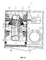
- numeral 1 generally designates a machine for automatically washing and drying wheels 3, hereinafter briefly referred to as machine 1.
- the machine 1 comprises a frame with a base 2 having a tank (not shown) defined therein, in which the liquid that is used for washing wheels 3, typically vehicle wheels, is collected.
- the base 2 has a box-like structure 4 fixed above it, which forms an inner chamber 5 and is closed at three peripheral sides and at the top, whereas the front wall is open and adapted to be closed by a panel 6 that is hinged at the base of the side walls 7 and 8 of the structure 4.
- the bottom of the chamber 5 is also normally open, to allow the washing liquid to spontaneously pour by gravity into the lower collection tank.
- the members for operating the machine 1, namely a pump unit 10 and a motor unit 11, are mounted beside the structure 4, on the base 2.
- Two transverse, parallel and horizontal rollers 12 and 13 are mounted in the chamber 5 that is designed to receive a wheel 3 to be washed and dried, namely in its lower portion, one of such rollers, namely the roller 12 being freely rotatable, whereas the roller 13 is mechanically connected to a coupling 14 for connection to the motor unit 11.
- rollers 12 and 13 provide support to the wheels 3 to be washed and dried, that are arranged in a substantially vertical position, with their center axis of rotation "A" substantially parallel to the two rollers 12 and 13.
- Sets of additional rollers 15 are mounted to the side walls 7 and 8 by brackets 16, such rollers being freely rotatable and having the special function of holding the wheels 3 in a vertical or substantially vertical position, as they are being washed and dried, as better explained below.
- Spraying and drying units are also mounted to the side walls 7 and 8, and emit jets of a washing liquid or compressed air drying flows toward the opposed faces of a wheel 3, as shown in Figures 2 and 3 , and generally referenced 19 and 20.
- Figure 3 the technical problem that is solved by the invention is shown in Figure 3 : as a wheel 3 is being dried, the directions of the compressed air flows 19 and 20, which have predetermined angles of incidence to the opposite faces of a wheel 3, typically generate components perpendicular to the faces of the wheel 3, which oppose to each other, as shown by arrows T1 and T2, thereby reducing drying effectiveness, and hindering normal pouring of the washing liquid from the surfaces of the faces of the wheel 3, particularly the inner surfaces 22 of the rim C.
- Figures 4 , 5 , 6 show a first embodiment of a pneumatic diagram of a system for actuating the drying units 113 and 213, which are part of the above mentioned units 17 and 18.
- numeral 113 designates a first drying unit and 213 designates a second drying unit, each comprising a plurality of ejecting nozzles 23 and 24, which are fed by respective pipes, namely a first pipe 143 and a second pipe 43.
- Both the first and second pipes 143 and 43 have first and second distribution valves 137 and 37 respectively, of the type having two operating positions P1 and P2.
- the position P1 is an open fluid flow position, whereas the position P2 is a closed fluid flow position.
- the first and second distribution valves are normally kept in the closed position by elastic means 41 and 141, which are preloaded with an adequate bias force acting upon the spools 40 and 140 of the two valves 37 and 137 respectively.
- the distribution valves 137 and 37 are reached by a first pipe 136 and a second pipe 36 respectively, which carry compressed air from a common source 35.
- An electronic control unit for controlling the operation of the machine 1 is generally referenced 44 and is connected via connecting lines 45 and 145 to the two spools 40 and 140, to actuate them upon request and switch the positions P1 and P2 of the distribution valves 37 and 137.
- numerals 38 and 138 designate the fluid inlet ports in the distribution valves 37 and 137
- numerals 39 and 139 designate the corresponding outlet ports to the two drying units 113 and 213.
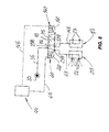
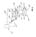
- a single pipe 36 is shown to extend from the compressed air source 35, and to end in a port 238 of a distribution valve 237 which has three operating positions in this embodiment, i.e. P3, P4, P5.
- the two positions P4 and P5 are open positions, allowing the compressed air flows to alternately reach the first drying unit 213 or the second drying unit 113, whereas the central position P3 is a closed position in which the passage of complex air is completely prevented.
- the electronic unit for controlling the operation of the machine 1 is referenced 44 also in this embodiment.
- the electronic control unit 44 is connected via connection lines 45 and 145 to the ends 40 and 140 of the spool, which controls the positions of the distribution valve 237 to actuate displacement thereof as required.
- the distribution valve 237 is normally kept in the closed position P3 by means of opposite bias forces provided by the two preloaded elastic elements 41 and 141.
- numeral 238 designates an inlet port of the valve 237
- numerals 239 and 339 designate the outlet ports to the first drying unit 213 and the second drying unit 113 respectively.
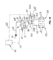
- the compressed air source 35 is shown to be connected, by a pipe 36 connected to an inlet port 338, to a first distribution valve 37 having two operating positions, namely an open position P1 and a closed position P2, said valve being normally kept in the closed position P2 by means of a preloaded elastic element 141, which pushes the spool 40 of the valve 37.
- the latter is in turn connected to a second distribution valve 437, also having two operating positions designated as P6 and P7, and normally kept in the operating position P6 by a second preloaded elastic element 541, by a further pipe that has one end connected to an outlet port 439 of the first valve 37 and an opposite end connected to an inlet port 438 of the second distribution valve 437, which has two outlet ports 539 and 639 respectively.
- the outlet port 539 is connected to the first drying unit 213 by a pipe 43 whereas the outlet port 639 is connected to the second drying unit 113 by a further pipe 143.
- the two operating positions P6 and P7 allow alternate communication of the inlet port 438 with one of the outlet ports 538 or 639.
- an electronic control unit 44 is provided, which is connected to the spools 40 and 540 of the two valves 37 and 437 by means of respective connection lines 45 and 145 to actuate the movements of the two spools and switch the operating positions P1 or P2 and P6 or P7.
- the electronic control unit 44 sends a first signal to the spool of the distribution valve 37, thereby causing it to switch to the open position P1, whereas the distribution valve 137 remains in the closed position P2.
- the wheel 3 to be dried receives the compressed air flow on one face for as long as is required for full removal of the washing water and drying.
- the latter sends an actuation pulse to the spool 140 of the distribution valve 137, which switches to the open position P1 and simultaneously stops the actuation pulse to the spool 40 of the distribution valve 37, which switches back to the closed position P2 under the bias of the elastic element 41 that was previously compressed in the open position.
- valves 37 and 137 are replaced by a single distribution valve 237 having three operating positions.
- valve 237 is in the closed configuration P3 and none of the two drying units 113 and 213 is fed with the compressed air generated by the source 35.
- the electronic control unit 44 sends an actuation pulse through the line 45, e.g. to the end 40 of the spool of the distribution valve 237, which switches to the position P4 as shown in Figure 8 , thereby compressing the elastic element 141, whereby the pipe 36 is connected to the pipe 43 and hence with the first drying unit 213 which eject the compressed air flow toward a first face of the wheel 3: this configuration is shown in Figure 8 .
- the latter sends an actuation pulse to the opposite end 140 of the spool of the distribution valve 237 and simultaneously stops the previous pulse to the end 40.
- the distribution valve 237 switches to the operating position P5 and the compressed air reaches the second drying unit 113, as shown in Figure 9 , such unit ejecting the flow of drying compressed air toward the face of the wheel 3 to be dried opposite to the previous face, for a second drying time, as preset in the electronic control unit 44.
- the electronic control unit 44 stops pulse transmission, and the elastic elements 41 and 141 restore the valve 237 to the normally closed position P3.
- the source 35 sends air through the pipe 36 to the inlet port 338 of the first distribution valve 37, which is kept in the closed position P2.
- the electronic control unit 44 sends a pulse to the first distribution valve 37 through the line 45 and switches it to the open position P1: this configuration is shown in Figure 11 .
- compressed air flows into the inlet port 338, flows out of the outlet port 439, flows into the inlet port 438 of the second distribution valve 437 and flows out of the outlet port 539, thereby reaching the first drying unit 213 which ejects drying air flows toward one of the faces of the wheel 3 to be dried.
- the electronic control unit 44 sends a switching signal to the second distribution valve 437 which switches to the position P6, preceding the position P7: this configuration is shown in Figure 12 .
- the compressed air that flows through the first distribution valve 37 reaches the inlet port 438 of the second distribution valve 437, flows out of the outlet port 639 thereof, and feeds the second drying unit 113 which ejects compressed air flows toward the face of the wheel 3 to be dried opposite to the previous face.
- the electronic control unit 44 stops the signals to both the first distribution valve 37 and the second distribution valve 437, which valves are biased by the action of their respective elastic return elements, and are automatically restored to their respective normal positions, i.e. the closed position P2 for the valve 37 and the distribution position P6 to the first drying unit 213.
- the first distribution valve 37 acts as an ON/OFF switch
- the second distribution valve 437 acts as a compressed air flow deflector, deflecting flows toward the first drying unit 213 or toward the second drying unit 113.
- the latter are emitted alternately by the drying units 113 and 213 do not oppose each other, with the surfaces of the wheels 3 being cleared of washing liquid residues in shorter times.
- drying cycles are repeated twice for each face of each wheel 3, to remove the residual water that may have flown to the opposite surface during a first drying cycle, and vice versa.
- drying times may be set for the two faces of each wheel 3, to account for the different areas of the surfaces to be dried, and typically to provide longer cycles for the inner surfaces 22 of the rim "C".
- the invention was found to fulfill the intended objects.
Landscapes
- Engineering & Computer Science (AREA)
- Mechanical Engineering (AREA)
- Cleaning In General (AREA)
- Detail Structures Of Washing Machines And Dryers (AREA)
- Vehicle Cleaning, Maintenance, Repair, Refitting, And Outriggers (AREA)
Claims (8)
- Eine Reifenwaschmaschine (1) mit:- einem Rahmen, der eine Waschstation (4) bildet, in der zu waschende Räder (3) so ausgebildet sind, dass sie einsetzbar sind,- einem ersten Sprühaggregat (17) mit einer Spülflüssigkeit, das an einer ersten Seite der Waschstation (4) angebaut ist und einem zweiten Sprühaggregat (18), das an einer zweiten, gegenüber liegenden Seite der Waschstation (4) angebaut ist, und- einem ersten Trocknungsaggregat (213), das an der ersten Seite der Waschstation (4) angebaut ist und einem zweiten Trocknungsaggregat (113), das an der zweiten, gegenüber liegenden Seite der Waschstation (4) angebaut ist,
dadurch gekennzeichnet, dass das erste Trocknungsaggregat (213) und das zweite Trocknungsaggregat (113) alternativ betätigt werden können mittels alternativen Betätigungseinrichtungen (44, 35, 37, 137), um mit alternierenden Trocknungszyklen zu arbeiten. - Maschine gemäß Anspruch 1, dadurch gekennzeichnet, dass das erste und das zweite Trocknungsaggregat umfassen:- eine Quelle (35) eines Trocknungsfluids unter Druck,- Fließleitungen (36, 136) für das Fluid von der Quelle (35) zum ersten Trocknungsaggregat (213) und zweiten Trocknungsaggregat (113), die in der Waschstation (4) angeordnet sind gegenüber einer jeweiligen Seite eines zu trocknenden Rades (3),- Steuereinrichtungen (37, 137) für die Fließleitungen (36, 136), die ausgelegt sind, die Quelle (35) wahlweise mit dem ersten oder zweiten Trocknungsaggregat (213, 113) zu verbinden.
- Maschine gemäß Anspruch 2, dadurch gekennzeichnet, dass die Fließleitungen umfassen:einen ersten Verbindungskanal (143), der die Quelle (35) mit dem ersten Trocknungsaggregat (213) verbindet,einen zweiten Verbindungskanal (43), der die Quelle (35) mit dem zweiten Trocknungsaggregat (113) verbindet.
- Maschine gemäß Anspruch 3 der vorhergehenden Ansprüche, dadurch gekennzeichnet, dass die Steuereinrichtungen umfassen:- ein erstes Ventil (137) mit mindestens zwei schaltbaren Betriebspunkten (P1, P2), die eine erste Verbindungsposition (P1) und eine zweite Schließposition (P2) umfassen, das an dem ersten Kanal (143) angebaut ist,- ein zweites Ventil (37) mit mindestens zwei schaltbaren Betriebspunkten (P1, P2), die eine erste Verbindungsposition (P1) und eine zweite Schließposition (P2) umfassen, das an dem zweiten Kanal (43) angebaut ist,- eine programmierbare, elektronische Schalteinheit (44) für das erste Ventil (137) und das zweite Ventil (37).
- Maschine gemäß Anspruch 4 der vorhergehenden Ansprüche, dadurch gekennzeichnet, dass das erste und das zweite Ventil (137, 37) normalerweise in die Schließpositionen (P2) gezwungen sind mittels zwingenden elastischen Einrichtungen (41, 141).
- Maschine gemäß Anspruch 1, dadurch gekennzeichnet, dass die ersten und zweiten Trocknungsaggregate (213, 113) jedes ein erstes und ein zweites Stutzengehäuse umfassen, wobei Enden eines ersten Kanals (143) und eines zweiten Kanals (43) jeweils fließen und wobei die ersten und zweiten Trocknungsaggregate versehen sind mit einer Vielzahl von drehbaren Auslassdüsen (23, 24).
- Maschine gemäß Anspruch 1, dadurch gekennzeichnet, dass die alternierenden Trocknungszyklen die selbe Dauer haben.
- Maschine gemäß Anspruch 1, dadurch gekennzeichnet, dass die alternierenden Trocknungszyklen unterschiedliche Dauer haben.
Priority Applications (1)
| Application Number | Priority Date | Filing Date | Title |
|---|---|---|---|
| PL13002034T PL2653358T3 (pl) | 2012-04-19 | 2013-04-18 | Maszyna do mycia koła |
Applications Claiming Priority (1)
| Application Number | Priority Date | Filing Date | Title |
|---|---|---|---|
| IT000103A ITMO20120103A1 (it) | 2012-04-19 | 2012-04-19 | Macchina per il lavaggio di ruote |
Publications (2)
| Publication Number | Publication Date |
|---|---|
| EP2653358A1 EP2653358A1 (de) | 2013-10-23 |
| EP2653358B1 true EP2653358B1 (de) | 2015-01-14 |
Family
ID=46124646
Family Applications (1)
| Application Number | Title | Priority Date | Filing Date |
|---|---|---|---|
| EP13002034.0A Active EP2653358B1 (de) | 2012-04-19 | 2013-04-18 | Radwaschmaschine |
Country Status (4)
| Country | Link |
|---|---|
| EP (1) | EP2653358B1 (de) |
| IT (1) | ITMO20120103A1 (de) |
| PL (1) | PL2653358T3 (de) |
| RU (1) | RU2621526C2 (de) |
Families Citing this family (3)
| Publication number | Priority date | Publication date | Assignee | Title |
|---|---|---|---|---|
| WO2015071505A1 (es) * | 2013-11-12 | 2015-05-21 | Ibasan S.A. | Máquina para lavado automático de ruedas de vehículos |
| CN108128284B (zh) * | 2017-12-21 | 2019-07-30 | 宁波高新区新柯保汽车科技有限公司 | 轮胎内石子清除装置 |
| SE548209C2 (en) * | 2024-06-03 | 2026-04-20 | Hedson Tech Ab | Improved wheel cleaning system |
Family Cites Families (7)
| Publication number | Priority date | Publication date | Assignee | Title |
|---|---|---|---|---|
| SE462384B (sv) * | 1988-04-22 | 1990-06-18 | Stern Leif Einar | Anordning foer rengoering av fordonshjul |
| FI81055C (fi) * | 1989-03-20 | 1990-09-10 | Eino Hakala | Anordning foer tvaettning av fordons hjul. |
| DE20110008U1 (de) * | 2001-06-16 | 2001-08-30 | Stadler, Johann, 94481 Grafenau | Wasch- oder Reinigungsvorrichtung für Fahrzeugreifen oder Fahrzeugräder |
| RU2213019C2 (ru) * | 2002-01-03 | 2003-09-27 | Козьев Евгений Васильевич | Машина для мойки автомобильных колес |
| RU2246413C2 (ru) * | 2002-11-28 | 2005-02-20 | Закрытое акционерное общество "Экологический промышленно-финансовый концерн "Мойдодыр" | Машина для мойки колес |
| EP1771323A2 (de) * | 2004-06-07 | 2007-04-11 | AHCON Wheel Service Equipment ApS | Vorrichtung zum waschen von fahrzeugrädern |
| DE102005009876A1 (de) * | 2005-03-01 | 2006-09-07 | Gerhard Paulus | Radwascheinrichtung für Fahrzeugräder |
-
2012
- 2012-04-19 IT IT000103A patent/ITMO20120103A1/it unknown
-
2013
- 2013-04-17 RU RU2013117695A patent/RU2621526C2/ru active
- 2013-04-18 PL PL13002034T patent/PL2653358T3/pl unknown
- 2013-04-18 EP EP13002034.0A patent/EP2653358B1/de active Active
Also Published As
| Publication number | Publication date |
|---|---|
| RU2013117695A (ru) | 2014-10-27 |
| ITMO20120103A1 (it) | 2013-10-20 |
| RU2621526C2 (ru) | 2017-06-06 |
| EP2653358A1 (de) | 2013-10-23 |
| PL2653358T3 (pl) | 2015-05-29 |
Similar Documents
| Publication | Publication Date | Title |
|---|---|---|
| EP2653358A1 (de) | Radwaschmaschine | |
| EP2773541B1 (de) | Verbesserte vorrichtung zum waschen der räder eines fahrzeuges in einer fahrzeugwaschanlage und entsprechende mit dieser vorrichtung ausgeführte neue waschzyklen | |
| EP1040787B1 (de) | Geschirrspülmaschine mit Sprüharmen | |
| KR102118684B1 (ko) | 도로 터널의 벽면 청소 장치 | |
| KR100824936B1 (ko) | 관 내벽의 페인트 분사장치 | |
| US20080314419A1 (en) | Equipment for cleaning cycles or motorcycles | |
| WO2009108165A1 (en) | Automated motorcycle wash | |
| KR102400181B1 (ko) | 터널 세척 및 도색장치 | |
| US20080185019A1 (en) | Wheel washing assembly for an automated carwash and method of operating the wheel washing assembly | |
| CN108407768B (zh) | 一种建筑垃圾运输车车轮用清洗装置 | |
| CN102556003A (zh) | 汽车底盘清洗烘干装置 | |
| CN107150664B (zh) | 车辆去泥清洗装置 | |
| US7143771B2 (en) | Salt truck wash system | |
| EP3028907B1 (de) | Vorrichtung zum Reinigen von Fahrzeugrädern | |
| KR102346194B1 (ko) | 이중 사이클론 유닛을 구비한 실외 청소장치 | |
| KR20150004555A (ko) | 세제 분사 방식의 고압세척 장치 | |
| RU2515018C2 (ru) | Распылительное устройство для машины для мытья колес | |
| EP2832594B1 (de) | Sprühvorrichtung für Radwaschmaschinen | |
| CN202400064U (zh) | 汽车底盘清洗烘干装置 | |
| KR20210121516A (ko) | 사이클론 유닛 및 이를 구비한 노면 청소장치 | |
| KR101742480B1 (ko) | 무구동회전방식 에어분사형 클리닝장치 | |
| CN203665746U (zh) | 流动式干燥机 | |
| CN204340979U (zh) | 一种挖掘机的履带冲洗装置 | |
| CN215210797U (zh) | 一种小型园林洒水车 | |
| JP2008261206A (ja) | 高圧洗浄車 |
Legal Events
| Date | Code | Title | Description |
|---|---|---|---|
| PUAI | Public reference made under article 153(3) epc to a published international application that has entered the european phase |
Free format text: ORIGINAL CODE: 0009012 |
|
| AK | Designated contracting states |
Kind code of ref document: A1 Designated state(s): AL AT BE BG CH CY CZ DE DK EE ES FI FR GB GR HR HU IE IS IT LI LT LU LV MC MK MT NL NO PL PT RO RS SE SI SK SM TR |
|
| AX | Request for extension of the european patent |
Extension state: BA ME |
|
| 17P | Request for examination filed |
Effective date: 20140331 |
|
| RBV | Designated contracting states (corrected) |
Designated state(s): AL AT BE BG CH CY CZ DE DK EE ES FI FR GB GR HR HU IE IS IT LI LT LU LV MC MK MT NL NO PL PT RO RS SE SI SK SM TR |
|
| GRAP | Despatch of communication of intention to grant a patent |
Free format text: ORIGINAL CODE: EPIDOSNIGR1 |
|
| INTG | Intention to grant announced |
Effective date: 20140730 |
|
| GRAS | Grant fee paid |
Free format text: ORIGINAL CODE: EPIDOSNIGR3 |
|
| GRAA | (expected) grant |
Free format text: ORIGINAL CODE: 0009210 |
|
| AK | Designated contracting states |
Kind code of ref document: B1 Designated state(s): AL AT BE BG CH CY CZ DE DK EE ES FI FR GB GR HR HU IE IS IT LI LT LU LV MC MK MT NL NO PL PT RO RS SE SI SK SM TR |
|
| REG | Reference to a national code |
Ref country code: GB Ref legal event code: FG4D |
|
| REG | Reference to a national code |
Ref country code: CH Ref legal event code: EP |
|
| REG | Reference to a national code |
Ref country code: IE Ref legal event code: FG4D |
|
| REG | Reference to a national code |
Ref country code: AT Ref legal event code: REF Ref document number: 706852 Country of ref document: AT Kind code of ref document: T Effective date: 20150215 |
|
| REG | Reference to a national code |
Ref country code: DE Ref legal event code: R096 Ref document number: 602013000811 Country of ref document: DE Effective date: 20150305 |
|
| REG | Reference to a national code |
Ref country code: SE Ref legal event code: TRGR |
|
| REG | Reference to a national code |
Ref country code: NL Ref legal event code: VDEP Effective date: 20150114 |
|
| REG | Reference to a national code |
Ref country code: PL Ref legal event code: T3 |
|
| REG | Reference to a national code |
Ref country code: AT Ref legal event code: MK05 Ref document number: 706852 Country of ref document: AT Kind code of ref document: T Effective date: 20150114 |
|
| REG | Reference to a national code |
Ref country code: LT Ref legal event code: MG4D |
|
| PG25 | Lapsed in a contracting state [announced via postgrant information from national office to epo] |
Ref country code: ES Free format text: LAPSE BECAUSE OF FAILURE TO SUBMIT A TRANSLATION OF THE DESCRIPTION OR TO PAY THE FEE WITHIN THE PRESCRIBED TIME-LIMIT Effective date: 20150114 Ref country code: NO Free format text: LAPSE BECAUSE OF FAILURE TO SUBMIT A TRANSLATION OF THE DESCRIPTION OR TO PAY THE FEE WITHIN THE PRESCRIBED TIME-LIMIT Effective date: 20150414 Ref country code: LT Free format text: LAPSE BECAUSE OF FAILURE TO SUBMIT A TRANSLATION OF THE DESCRIPTION OR TO PAY THE FEE WITHIN THE PRESCRIBED TIME-LIMIT Effective date: 20150114 Ref country code: BG Free format text: LAPSE BECAUSE OF FAILURE TO SUBMIT A TRANSLATION OF THE DESCRIPTION OR TO PAY THE FEE WITHIN THE PRESCRIBED TIME-LIMIT Effective date: 20150414 Ref country code: FI Free format text: LAPSE BECAUSE OF FAILURE TO SUBMIT A TRANSLATION OF THE DESCRIPTION OR TO PAY THE FEE WITHIN THE PRESCRIBED TIME-LIMIT Effective date: 20150114 Ref country code: HR Free format text: LAPSE BECAUSE OF FAILURE TO SUBMIT A TRANSLATION OF THE DESCRIPTION OR TO PAY THE FEE WITHIN THE PRESCRIBED TIME-LIMIT Effective date: 20150114 |
|
| PG25 | Lapsed in a contracting state [announced via postgrant information from national office to epo] |
Ref country code: AT Free format text: LAPSE BECAUSE OF FAILURE TO SUBMIT A TRANSLATION OF THE DESCRIPTION OR TO PAY THE FEE WITHIN THE PRESCRIBED TIME-LIMIT Effective date: 20150114 Ref country code: RS Free format text: LAPSE BECAUSE OF FAILURE TO SUBMIT A TRANSLATION OF THE DESCRIPTION OR TO PAY THE FEE WITHIN THE PRESCRIBED TIME-LIMIT Effective date: 20150114 Ref country code: NL Free format text: LAPSE BECAUSE OF FAILURE TO SUBMIT A TRANSLATION OF THE DESCRIPTION OR TO PAY THE FEE WITHIN THE PRESCRIBED TIME-LIMIT Effective date: 20150114 Ref country code: LV Free format text: LAPSE BECAUSE OF FAILURE TO SUBMIT A TRANSLATION OF THE DESCRIPTION OR TO PAY THE FEE WITHIN THE PRESCRIBED TIME-LIMIT Effective date: 20150114 Ref country code: IS Free format text: LAPSE BECAUSE OF FAILURE TO SUBMIT A TRANSLATION OF THE DESCRIPTION OR TO PAY THE FEE WITHIN THE PRESCRIBED TIME-LIMIT Effective date: 20150514 Ref country code: GR Free format text: LAPSE BECAUSE OF FAILURE TO SUBMIT A TRANSLATION OF THE DESCRIPTION OR TO PAY THE FEE WITHIN THE PRESCRIBED TIME-LIMIT Effective date: 20150415 |
|
| REG | Reference to a national code |
Ref country code: DE Ref legal event code: R097 Ref document number: 602013000811 Country of ref document: DE |
|
| PG25 | Lapsed in a contracting state [announced via postgrant information from national office to epo] |
Ref country code: RO Free format text: LAPSE BECAUSE OF FAILURE TO SUBMIT A TRANSLATION OF THE DESCRIPTION OR TO PAY THE FEE WITHIN THE PRESCRIBED TIME-LIMIT Effective date: 20150114 Ref country code: DK Free format text: LAPSE BECAUSE OF FAILURE TO SUBMIT A TRANSLATION OF THE DESCRIPTION OR TO PAY THE FEE WITHIN THE PRESCRIBED TIME-LIMIT Effective date: 20150114 Ref country code: EE Free format text: LAPSE BECAUSE OF FAILURE TO SUBMIT A TRANSLATION OF THE DESCRIPTION OR TO PAY THE FEE WITHIN THE PRESCRIBED TIME-LIMIT Effective date: 20150114 Ref country code: SK Free format text: LAPSE BECAUSE OF FAILURE TO SUBMIT A TRANSLATION OF THE DESCRIPTION OR TO PAY THE FEE WITHIN THE PRESCRIBED TIME-LIMIT Effective date: 20150114 Ref country code: CZ Free format text: LAPSE BECAUSE OF FAILURE TO SUBMIT A TRANSLATION OF THE DESCRIPTION OR TO PAY THE FEE WITHIN THE PRESCRIBED TIME-LIMIT Effective date: 20150114 |
|
| PLBE | No opposition filed within time limit |
Free format text: ORIGINAL CODE: 0009261 |
|
| STAA | Information on the status of an ep patent application or granted ep patent |
Free format text: STATUS: NO OPPOSITION FILED WITHIN TIME LIMIT |
|
| PG25 | Lapsed in a contracting state [announced via postgrant information from national office to epo] |
Ref country code: LU Free format text: LAPSE BECAUSE OF FAILURE TO SUBMIT A TRANSLATION OF THE DESCRIPTION OR TO PAY THE FEE WITHIN THE PRESCRIBED TIME-LIMIT Effective date: 20150418 Ref country code: MC Free format text: LAPSE BECAUSE OF FAILURE TO SUBMIT A TRANSLATION OF THE DESCRIPTION OR TO PAY THE FEE WITHIN THE PRESCRIBED TIME-LIMIT Effective date: 20150114 |
|
| 26N | No opposition filed |
Effective date: 20151015 |
|
| PG25 | Lapsed in a contracting state [announced via postgrant information from national office to epo] |
Ref country code: IT Free format text: LAPSE BECAUSE OF FAILURE TO SUBMIT A TRANSLATION OF THE DESCRIPTION OR TO PAY THE FEE WITHIN THE PRESCRIBED TIME-LIMIT Effective date: 20150114 |
|
| REG | Reference to a national code |
Ref country code: IE Ref legal event code: MM4A |
|
| REG | Reference to a national code |
Ref country code: FR Ref legal event code: ST Effective date: 20151231 |
|
| PG25 | Lapsed in a contracting state [announced via postgrant information from national office to epo] |
Ref country code: FR Free format text: LAPSE BECAUSE OF NON-PAYMENT OF DUE FEES Effective date: 20150430 Ref country code: SI Free format text: LAPSE BECAUSE OF FAILURE TO SUBMIT A TRANSLATION OF THE DESCRIPTION OR TO PAY THE FEE WITHIN THE PRESCRIBED TIME-LIMIT Effective date: 20150114 |
|
| PG25 | Lapsed in a contracting state [announced via postgrant information from national office to epo] |
Ref country code: IE Free format text: LAPSE BECAUSE OF NON-PAYMENT OF DUE FEES Effective date: 20150418 |
|
| PG25 | Lapsed in a contracting state [announced via postgrant information from national office to epo] |
Ref country code: BE Free format text: LAPSE BECAUSE OF FAILURE TO SUBMIT A TRANSLATION OF THE DESCRIPTION OR TO PAY THE FEE WITHIN THE PRESCRIBED TIME-LIMIT Effective date: 20150114 |
|
| REG | Reference to a national code |
Ref country code: CH Ref legal event code: PL |
|
| PG25 | Lapsed in a contracting state [announced via postgrant information from national office to epo] |
Ref country code: MT Free format text: LAPSE BECAUSE OF FAILURE TO SUBMIT A TRANSLATION OF THE DESCRIPTION OR TO PAY THE FEE WITHIN THE PRESCRIBED TIME-LIMIT Effective date: 20150114 |
|
| PG25 | Lapsed in a contracting state [announced via postgrant information from national office to epo] |
Ref country code: CH Free format text: LAPSE BECAUSE OF NON-PAYMENT OF DUE FEES Effective date: 20160430 Ref country code: LI Free format text: LAPSE BECAUSE OF NON-PAYMENT OF DUE FEES Effective date: 20160430 |
|
| PG25 | Lapsed in a contracting state [announced via postgrant information from national office to epo] |
Ref country code: HU Free format text: LAPSE BECAUSE OF FAILURE TO SUBMIT A TRANSLATION OF THE DESCRIPTION OR TO PAY THE FEE WITHIN THE PRESCRIBED TIME-LIMIT; INVALID AB INITIO Effective date: 20130418 |
|
| PG25 | Lapsed in a contracting state [announced via postgrant information from national office to epo] |
Ref country code: CY Free format text: LAPSE BECAUSE OF FAILURE TO SUBMIT A TRANSLATION OF THE DESCRIPTION OR TO PAY THE FEE WITHIN THE PRESCRIBED TIME-LIMIT Effective date: 20150114 |
|
| PG25 | Lapsed in a contracting state [announced via postgrant information from national office to epo] |
Ref country code: TR Free format text: LAPSE BECAUSE OF FAILURE TO SUBMIT A TRANSLATION OF THE DESCRIPTION OR TO PAY THE FEE WITHIN THE PRESCRIBED TIME-LIMIT Effective date: 20150114 |
|
| GBPC | Gb: european patent ceased through non-payment of renewal fee |
Effective date: 20170418 |
|
| PG25 | Lapsed in a contracting state [announced via postgrant information from national office to epo] |
Ref country code: GB Free format text: LAPSE BECAUSE OF NON-PAYMENT OF DUE FEES Effective date: 20170418 |
|
| PG25 | Lapsed in a contracting state [announced via postgrant information from national office to epo] |
Ref country code: SM Free format text: LAPSE BECAUSE OF FAILURE TO SUBMIT A TRANSLATION OF THE DESCRIPTION OR TO PAY THE FEE WITHIN THE PRESCRIBED TIME-LIMIT Effective date: 20150114 |
|
| PG25 | Lapsed in a contracting state [announced via postgrant information from national office to epo] |
Ref country code: PT Free format text: LAPSE BECAUSE OF FAILURE TO SUBMIT A TRANSLATION OF THE DESCRIPTION OR TO PAY THE FEE WITHIN THE PRESCRIBED TIME-LIMIT Effective date: 20150114 Ref country code: MK Free format text: LAPSE BECAUSE OF FAILURE TO SUBMIT A TRANSLATION OF THE DESCRIPTION OR TO PAY THE FEE WITHIN THE PRESCRIBED TIME-LIMIT Effective date: 20150114 |
|
| PG25 | Lapsed in a contracting state [announced via postgrant information from national office to epo] |
Ref country code: AL Free format text: LAPSE BECAUSE OF FAILURE TO SUBMIT A TRANSLATION OF THE DESCRIPTION OR TO PAY THE FEE WITHIN THE PRESCRIBED TIME-LIMIT Effective date: 20150114 |
|
| REG | Reference to a national code |
Ref country code: DE Ref legal event code: R081 Ref document number: 602013000811 Country of ref document: DE Owner name: NEXION S.P.A., IT Free format text: FORMER OWNER: TECO S.R.L., CORREGGIO, REGGIO EMILIA, IT |
|
| P01 | Opt-out of the competence of the unified patent court (upc) registered |
Effective date: 20230530 |
|
| PGFP | Annual fee paid to national office [announced via postgrant information from national office to epo] |
Ref country code: SE Payment date: 20250228 Year of fee payment: 13 |
|
| PGFP | Annual fee paid to national office [announced via postgrant information from national office to epo] |
Ref country code: DE Payment date: 20250428 Year of fee payment: 13 |
|
| PGFP | Annual fee paid to national office [announced via postgrant information from national office to epo] |
Ref country code: PL Payment date: 20260324 Year of fee payment: 14 |