EP2653320A2 - Pneumatic tire - Google Patents
Pneumatic tire Download PDFInfo
- Publication number
- EP2653320A2 EP2653320A2 EP13163870.2A EP13163870A EP2653320A2 EP 2653320 A2 EP2653320 A2 EP 2653320A2 EP 13163870 A EP13163870 A EP 13163870A EP 2653320 A2 EP2653320 A2 EP 2653320A2
- Authority
- EP
- European Patent Office
- Prior art keywords
- shoulder
- tire
- groove
- main groove
- grooves
- Prior art date
- Legal status (The legal status is an assumption and is not a legal conclusion. Google has not performed a legal analysis and makes no representation as to the accuracy of the status listed.)
- Granted
Links
Images


Classifications
-
- B—PERFORMING OPERATIONS; TRANSPORTING
- B60—VEHICLES IN GENERAL
- B60C—VEHICLE TYRES; TYRE INFLATION; TYRE CHANGING; CONNECTING VALVES TO INFLATABLE ELASTIC BODIES IN GENERAL; DEVICES OR ARRANGEMENTS RELATED TO TYRES
- B60C11/00—Tyre tread bands; Tread patterns; Anti-skid inserts
- B60C11/03—Tread patterns
- B60C11/0306—Patterns comprising block rows or discontinuous ribs
-
- B—PERFORMING OPERATIONS; TRANSPORTING
- B60—VEHICLES IN GENERAL
- B60C—VEHICLE TYRES; TYRE INFLATION; TYRE CHANGING; CONNECTING VALVES TO INFLATABLE ELASTIC BODIES IN GENERAL; DEVICES OR ARRANGEMENTS RELATED TO TYRES
- B60C11/00—Tyre tread bands; Tread patterns; Anti-skid inserts
- B60C11/03—Tread patterns
- B60C11/0327—Tread patterns characterised by special properties of the tread pattern
- B60C11/0332—Tread patterns characterised by special properties of the tread pattern by the footprint-ground contacting area of the tyre tread
-
- B—PERFORMING OPERATIONS; TRANSPORTING
- B60—VEHICLES IN GENERAL
- B60C—VEHICLE TYRES; TYRE INFLATION; TYRE CHANGING; CONNECTING VALVES TO INFLATABLE ELASTIC BODIES IN GENERAL; DEVICES OR ARRANGEMENTS RELATED TO TYRES
- B60C11/00—Tyre tread bands; Tread patterns; Anti-skid inserts
- B60C11/03—Tread patterns
- B60C11/0318—Tread patterns irregular patterns with particular pitch sequence
-
- B—PERFORMING OPERATIONS; TRANSPORTING
- B60—VEHICLES IN GENERAL
- B60C—VEHICLE TYRES; TYRE INFLATION; TYRE CHANGING; CONNECTING VALVES TO INFLATABLE ELASTIC BODIES IN GENERAL; DEVICES OR ARRANGEMENTS RELATED TO TYRES
- B60C11/00—Tyre tread bands; Tread patterns; Anti-skid inserts
- B60C11/03—Tread patterns
- B60C2011/0337—Tread patterns characterised by particular design features of the pattern
- B60C2011/0339—Grooves
- B60C2011/0341—Circumferential grooves
- B60C2011/0346—Circumferential grooves with zigzag shape
-
- B—PERFORMING OPERATIONS; TRANSPORTING
- B60—VEHICLES IN GENERAL
- B60C—VEHICLE TYRES; TYRE INFLATION; TYRE CHANGING; CONNECTING VALVES TO INFLATABLE ELASTIC BODIES IN GENERAL; DEVICES OR ARRANGEMENTS RELATED TO TYRES
- B60C11/00—Tyre tread bands; Tread patterns; Anti-skid inserts
- B60C11/03—Tread patterns
- B60C2011/0337—Tread patterns characterised by particular design features of the pattern
- B60C2011/0339—Grooves
- B60C2011/0358—Lateral grooves, i.e. having an angle of 45 to 90 degees to the equatorial plane
- B60C2011/0365—Lateral grooves, i.e. having an angle of 45 to 90 degees to the equatorial plane characterised by width
-
- B—PERFORMING OPERATIONS; TRANSPORTING
- B60—VEHICLES IN GENERAL
- B60C—VEHICLE TYRES; TYRE INFLATION; TYRE CHANGING; CONNECTING VALVES TO INFLATABLE ELASTIC BODIES IN GENERAL; DEVICES OR ARRANGEMENTS RELATED TO TYRES
- B60C11/00—Tyre tread bands; Tread patterns; Anti-skid inserts
- B60C11/03—Tread patterns
- B60C2011/0337—Tread patterns characterised by particular design features of the pattern
- B60C2011/0339—Grooves
- B60C2011/0358—Lateral grooves, i.e. having an angle of 45 to 90 degees to the equatorial plane
- B60C2011/0372—Lateral grooves, i.e. having an angle of 45 to 90 degees to the equatorial plane with particular inclination angles
-
- B—PERFORMING OPERATIONS; TRANSPORTING
- B60—VEHICLES IN GENERAL
- B60C—VEHICLE TYRES; TYRE INFLATION; TYRE CHANGING; CONNECTING VALVES TO INFLATABLE ELASTIC BODIES IN GENERAL; DEVICES OR ARRANGEMENTS RELATED TO TYRES
- B60C11/00—Tyre tread bands; Tread patterns; Anti-skid inserts
- B60C11/03—Tread patterns
- B60C2011/0337—Tread patterns characterised by particular design features of the pattern
- B60C2011/0339—Grooves
- B60C2011/0374—Slant grooves, i.e. having an angle of about 5 to 35 degrees to the equatorial plane
-
- B—PERFORMING OPERATIONS; TRANSPORTING
- B60—VEHICLES IN GENERAL
- B60C—VEHICLE TYRES; TYRE INFLATION; TYRE CHANGING; CONNECTING VALVES TO INFLATABLE ELASTIC BODIES IN GENERAL; DEVICES OR ARRANGEMENTS RELATED TO TYRES
- B60C11/00—Tyre tread bands; Tread patterns; Anti-skid inserts
- B60C11/03—Tread patterns
- B60C2011/0337—Tread patterns characterised by particular design features of the pattern
- B60C2011/0386—Continuous ribs
- B60C2011/0388—Continuous ribs provided at the equatorial plane
Definitions
- the present invention relates to a pneumatic tire capable of reducing tire noise without deteriorating other performance.
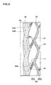
- JP2004-58839A1 discloses a pneumatic tire as shown in Fig. 5 .
- the tire includes a tread portion provided with: a shoulder main groove "a" disposed the nearest side of the tread edge Te; a plurality of shoulder lateral grooves b extending from the shoulder main groove toward the tread edge Te; and a plurality of middle lateral grooves c extending from the shoulder main groove "a" toward the tire equatorial plane Co.
- the shoulder lateral grooves b include a first shoulder lateral groove bL having a large groove width and a second shoulder lateral groove bS having a small groove width compared to the first shoulder lateral groove bL.
- the first shoulder lateral groove bL and the second shoulder lateral groove bS are alternately arranged in a tire circumferential direction.
- first and second shoulder lateral grooves bL, bS have the following relations: WLi / WSi ⁇ WLo / WSo .
- WLi and WLo are groove widths of the first shoulder lateral groove bL at the axially inner and outer ends, respectively, and WSi and WSo are groove widths of the second shoulder lateral groove bS at the axially inner and outer ends, respectively.
- first and second shoulder lateral grooves bL, bS arranged alternately with different groove widths, pitch noise is modulated into a wide frequency range so that the pattern noise turns to the so called white noise. Additionally, since the first shoulder lateral groove bL has a large groove width WLo at the tread edge Te, mud performance of the tire improves. Additionally, since the first shoulder lateral groove bL has the small groove width WLi at the inner end so as to decrease a groove volume thereof, tire noise reduces.
- the present invention has been worked out in light of the circumstances described above, and has a main object of providing a pneumatic tire capable of reducing tire noise without deteriorating other performance such as wet performance and mud performance.
- a pneumatic tire comprising a tread portion provided with a circumferentially and continuously extending shoulder main groove disposed the nearest side of a tread edge, a plurality of shoulder lateral grooves each extending from the shoulder main groove toward the tread edge, and a plurality of middle lateral grooves each extending from the shoulder main groove toward a tire equatorial plane, the shoulder main groove extending in a zigzag manner through axially innermost points and axially outermost points alternately, each middle lateral groove extending from each innermost point of the shoulder main groove with an angle ⁇ m of from 50 to 75 degrees with respect to an axial direction of the tire, and each shoulder lateral groove extending from the shoulder main groove, the shoulder lateral groove having the same inclination direction with the middle lateral groove at an angle ⁇ s of from 10 to 25 degrees with respect to the axial direction of the tire, wherein the number "ns" of shoulder lateral grooves is larger than the number "nm" of middle lateral groove
- the tread edges are the axial outermost edges of the ground contacting patch of the tread portion which occurs under a normally inflated loaded condition.
- the normally inflated loaded condition is such that the tire is mounted on a standard wheel rim and inflated to a standard pressure and loaded with a standard tire load.
- the standard wheel rim means a wheel rim officially approved or recommended for the tire by standards organizations, the standard wheel rim is the "standard rim” specified in JATMA, the "Measuring Rim” in ETRTO, and the "Design Rim” in TRA or the like, for example.
- the standard pressure means the “maximum air pressure” in JATMA, the “Inflation Pressure” in ETRTO, and the maximum pressure given in the "Tire Load Limits at Various Cold Inflation Pressures” table in TRA or the like. In case of passenger car tires, however, the standard pressure is uniformly defined by 180 kPa.
- the standard load is the "maximum load capacity" in JATMA, the “Load Capacity” in ETRTO, and the maximum value given in the above-mentioned table in TRA or the like.
- a pneumatic tire 1 in accordance with the present invention has a tread portion 2 provided with circumferentially and continuously extending main grooves 3 including a shoulder main groove 3s arranged at the nearest side of a tread edge Te, a plurality of shoulder lateral grooves 4 each extending from the shoulder main groove 3s toward the tread edge Te and a plurality of middle lateral grooves 5 each extending from the shoulder main groove 3s toward a tire equatorial plane Co.
- the main grooves 3 include a pair of shoulder main grooves 3s and a pair of crown main grooves 3c between the shoulder main grooves 3s.
- the crown main grooves 3c are arranged both sides of the tire equatorial plane Co.
- the main grooves 3 separate the tread portion 2 into five land portions which include: a pair of shoulder portions 6s, 6s each between the shoulder main groove 3s and the tread edge Te at each side of the tire equatorial plane Co; a pair of middle portions 6m each between the shoulder main groove 3s and the crown main groove 3c at each side of the tire equatorial plane Co; and a crown portion 6c between a pair of crown main grooves 3c.
- the main grooves 3 may include a pair of shoulder main grooves 3s, 3s and one crown main groove 3c so that four land portions are separated on the tread portion 2 that include a pair of crown portions 6m, 6m each between the crown main groove 3c and the shoulder main groove 3s, and a pair of shoulder portions 6s, 6s.
- the shoulder main groove 3c extends in a zigzag manner through axially innermost points 7 and axially outermost points 8 alternately so as to prevent a large pipe resonance noise generated therein.
- the shoulder main groove 3s comprises a plurality of zigzag elements 9 between adjacent innermost points 7, 7 as repeated pitches each of which includes a first inclined part 9a extending from the outermost point 8 to one of the innermost points 7 and a second inclined part 9b extending from the outermost point 8 to the other innermost point 7.
- Each of the first and second inclined parts 9a, 9b may have a straight shape or a shape having a curved portion at least partially therein. In this embodiment, the first inclined part 9a has a curved shape, and the second inclined part 9b has a straight shape.
- the zigzag element 9 of the shoulder main groove 3c has a pitch length L0 between adjacent innermost points 7, 7 in a circumferential direction of the tire.
- the outermost point 8 between the adjacent innermost points 7, 7 is offset to one of the innermost points 7.
- a circumferential length La between the outermost point 8 and the innermost point 7 closest to the outermost point is in a range of 0.1 to 0.3 times with respect to the pitch length L0.
- Each shoulder lateral groove 4 extends from the shoulder main groove 3s to the tread edge Te with an angle ⁇ s of from 10 to 25 degrees with respect to the axial direction of the tire so that each shoulder lateral groove 4 is inclined the same direction.
- the shoulder portion 6s is divided into a plurality of blocks by shoulder lateral grooves 4.
- Shoulder lateral grooves 4 include a first shoulder lateral groove 4A having a large groove width and a second shoulder lateral groove 4B having a small groove width compared to the first shoulder lateral groove 4A.
- one first shoulder lateral groove 4A is arranged every two second shoulder lateral grooves 4B.
- the first shoulder lateral groove 4A comprises an axially outer wide portion 10a having a groove width W10a, an axially inner narrow portion 10b having a groove width W10b and a tapered portion 10c therebetween having a groove width being gradually changing.
- the groove width W10a of the wide portion 10a is not less than 1.2 times with respect to the groove width W10b of the narrow portion 10b.
- the second shoulder lateral groove 4B comprises an axially outer wide portion 11a having a groove width W11a, an axially inner narrow portion 11b having a groove width W11b and a tapered portion 11c therebetween having a groove width being gradually changing.
- the groove width W11a of the wide portion 11a is not less than 1.2 times with respect to the groove width W11b of the narrow portion 11b.
- the groove width W10b of the narrow portion 10b of the first shoulder lateral groove 4A is larger than the groove width W11a of the wide portion 11a of the second shoulder lateral groove 4B.
- the shoulder lateral grooves 4 include at lest two kinds of grooves 4A, 4B having different groove widths, pitch noise generated from shoulder lateral grooves 4 is modulated into a wide frequency range.
- the wide portions 10a and 11a having large groove widths are provided at the tread edge Te which has a large contribution to mud performance, an improved mud performance of the tire is obtained.
- the narrow portions 10b and 11b having small groove widths are provided toward the tire equatorial plane Co which has a large contribution to tire noise, noise performance of the tire is improved. Namely, the tire 1 in accordance with the present embodiment reduces tire noise without deteriorating mud performance.
- Each middle lateral groove 5 extends from each innermost point 7 of the shoulder main groove 3s having an angle ⁇ m of from 50 to 75 degrees with respect to the axial direction of the tire.
- Each middle lateral groove 5 has the same inclination direction with shoulder lateral groove 4.
- the middle portion 6m is provided with a circumferentially extending sub groove 15 in an axially center region thereof which divides the middle portion 6m into an axially inner middle region 6mi and an axially outer middle region 6mo.
- the sub groove 15 extends in a zigzag manner having the same pitches with the shoulder main grooves 3s, and has a groove width smaller than that of main grooves 3.
- Each middle lateral groove 5 traverses the axially outer middle region 6mo so that the outer middle region 6mo is divided into a plurality of blocks.
- each middle lateral groove 5 extends from each innermost point 7 of the shoulder main groove 3s, the number “nm” of middle lateral grooves 5 is the same with the number of zigzag elements 9 of the shoulder main grooves 3s in each side of the tire equatorial plane Co.
- the number “ns” of shoulder lateral grooves 4 is larger than the number “nm” of middle lateral grooves 5 in each side of the tire equatorial plane Co. Accordingly, since shoulder and middle lateral grooves 5 are arranged different positions in the circumferential direction of the tire, most of shoulder and the middle lateral grooves 4, 5 come into contact on the ground in different timing. Additionally, since shoulder and middle lateral grooves 4, 5 are provided in the different numbers in each side of the tire equatorial plane Co, pitch noise generated from lateral grooves 4, 5 is modulated into a wide frequency range so that tire noise is reduced.
- a ratio ns/nm of the number "ns" of shoulder lateral grooves 4 to the number “nm” of middle lateral grooves 5 is 3/2.
- the ratio ns/nm is an integer, a peak noise with a frequency that is an integral multiple of the pitch noise frequency of the middle lateral grooves 5 may be generated.
- the ratio ns/nm is not less than 2.0, uneven wear of the tread portion 2 or low steering stability of the tire may be caused by offering an enhanced large pattern rigidity between the outer middle region 6mo and the inner middle region 6mi.
- 4/3, 5/3, 5/4 and 7/4 may be also used for the ratio ns/nm.
- Fig. 4 shows a plan view of a footprint F of the tread portion 2.
- the footprint F in this embodiment has a circumferential contact end Ym of the outer middle region 6mo with an angle ⁇ m with respect to the tire axial direction which differs from the angle ⁇ m.
- the footprint F in this embodiment has a circumferential contact end Ys of the shoulder portion 6s with an angle ⁇ s with respect to the tire axial direction which differs from the angle ⁇ s.
- each of middle and shoulder lateral grooves 5, 4 gradually comes into contact with the road.
- the inner middle region 6mi is provided with a plurality of inner middle lateral grooves 16 which divide the inner middle region 6mi into a plurality of blocks.
- Each inner middle lateral grooves 16 extend from each innermost point 17 toward the tire equatorial plane Co having an angle ⁇ mi of from 50 to 75 degrees with respect to the tire axial direction with the same inclination with the middle lateral groove 5.
- the inner middle lateral grooves 16 have substantially same configuration with the middle lateral grooves 5.
- the crown main groove 3c extends in a zigzag manner having the same number of the zigzag elements of the shoulder main groove 3s.
- the crown main groove 3c preferably has a groove width larger than that of the shoulder main grooves 3s.
- the crown main groove 3c preferably has zigzag amplitude WJ smaller than that of shoulder main grooves 3s.
- a zigzag shape defined by the groove edge 3cE (a ridgeline between the ground contact surface and a groove wall) and a zigzag shape defined by the groove bottom edge 3cB are different from each other for preventing pipe resonance in the groove.
- at least one factor such as zigzag amplitude, a pitch length and a zigzag phase is different from each other between the zigzag shapes 3cE and 3cB.
- zigzag amplitude and phase are different between the zigzag shapes 3cE and 3cB.
- Each tire has substantially the same crown main groove 3c and sub grooves 15. Additionally, each tire has the same structure as regards the number of zigzag elements, zigzag amplitude, groove width and groove depth of shoulder main groove 3s except for the ratio La/L0. In addition, each tire has the same structure as regards the inclination direction, number of grooves, groove width and groove depth of the middle lateral groove 5 except for the angle ⁇ m. Although each tire has the different shoulder lateral groove 4 as regards the angle ⁇ s, number "ns" of grooves and configuration about the first and second shoulder lateral grooves 4A and 4B, each tire has the same total groove area of shoulder lateral grooves 4. Test methods are as follows.
- Each test tire was installed on four wheels of a SUV having a 5,600cc displacement using a rim of 20x9J with an internal pressure of 200kPa.
- a test driver drove the SUV on a test course having a dry asphalt road, and evaluated internal vehicle noise by his feeling. The results are shown with an index of 100 representing a value in Ref. 1. The larger the value, the better the performance is.
- a test driver drove the SUV on a road with 6mm water deep and measured the speed at which hydroplaning phenomenon occurred. Each test result was shown with an index of 100 representing a value in Ref. 1. The larger the value, the better the performance is.
- Example tires in accordance with the present invention can be effectively improved tire noise while maintaining wet performance.
Abstract
Description
- The present invention relates to a pneumatic tire capable of reducing tire noise without deteriorating other performance.
- In order to improve mud performance of tire while reducing tire noise,
JP2004-58839A1 Fig. 5 . The tire includes a tread portion provided with: a shoulder main groove "a" disposed the nearest side of the tread edge Te; a plurality of shoulder lateral grooves b extending from the shoulder main groove toward the tread edge Te; and a plurality of middle lateral grooves c extending from the shoulder main groove "a" toward the tire equatorial plane Co. - The shoulder lateral grooves b include a first shoulder lateral groove bL having a large groove width and a second shoulder lateral groove bS having a small groove width compared to the first shoulder lateral groove bL. The first shoulder lateral groove bL and the second shoulder lateral groove bS are alternately arranged in a tire circumferential direction.
- Additionally, the first and second shoulder lateral grooves bL, bS have the following relations:

- Here, WLi and WLo are groove widths of the first shoulder lateral groove bL at the axially inner and outer ends, respectively, and WSi and WSo are groove widths of the second shoulder lateral groove bS at the axially inner and outer ends, respectively.
- Since the tire above has the first and second shoulder lateral grooves bL, bS arranged alternately with different groove widths, pitch noise is modulated into a wide frequency range so that the pattern noise turns to the so called white noise. Additionally, since the first shoulder lateral groove bL has a large groove width WLo at the tread edge Te, mud performance of the tire improves. Additionally, since the first shoulder lateral groove bL has the small groove width WLi at the inner end so as to decrease a groove volume thereof, tire noise reduces.
- However, consumers request still further improved tire with low noise.
- The present invention has been worked out in light of the circumstances described above, and has a main object of providing a pneumatic tire capable of reducing tire noise without deteriorating other performance such as wet performance and mud performance.
- In accordance with the present invention, there is provided a pneumatic tire comprising a tread portion provided with a circumferentially and continuously extending shoulder main groove disposed the nearest side of a tread edge, a plurality of shoulder lateral grooves each extending from the shoulder main groove toward the tread edge, and a plurality of middle lateral grooves each extending from the shoulder main groove toward a tire equatorial plane, the shoulder main groove extending in a zigzag manner through axially innermost points and axially outermost points alternately, each middle lateral groove extending from each innermost point of the shoulder main groove with an angle θm of from 50 to 75 degrees with respect to an axial direction of the tire, and each shoulder lateral groove extending from the shoulder main groove, the shoulder lateral groove having the same inclination direction with the middle lateral groove at an angle θs of from 10 to 25 degrees with respect to the axial direction of the tire, wherein the number "ns" of shoulder lateral grooves is larger than the number "nm" of middle lateral grooves.
- The tread edges are the axial outermost edges of the ground contacting patch of the tread portion which occurs under a normally inflated loaded condition.
- The normally inflated loaded condition is such that the tire is mounted on a standard wheel rim and inflated to a standard pressure and loaded with a standard tire load.
- The standard wheel rim means a wheel rim officially approved or recommended for the tire by standards organizations, the standard wheel rim is the "standard rim" specified in JATMA, the "Measuring Rim" in ETRTO, and the "Design Rim" in TRA or the like, for example.
- The standard pressure means the "maximum air pressure" in JATMA, the "Inflation Pressure" in ETRTO, and the maximum pressure given in the "Tire Load Limits at Various Cold Inflation Pressures" table in TRA or the like. In case of passenger car tires, however, the standard pressure is uniformly defined by 180 kPa.
- The standard load is the "maximum load capacity" in JATMA, the "Load Capacity" in ETRTO, and the maximum value given in the above-mentioned table in TRA or the like.
-
-
Fig. 1 is a development view of a tread portion showing an embodiment of the present invention. -
Fig. 2 is an enlarged development view of a shoulder main groove ofFig. 1 . -
Fig. 3 is an enlarged development view of a crown main groove ofFig. 1 . -
Fig. 4 is a plan view showing a footprint of the tread portion. -
Fig. 5 is a development view of a tread portion showing a conventional tire. - An embodiment of the present invention will be explained below with reference to the accompanying drawings.
- Referring to
Fig. 1 , apneumatic tire 1 in accordance with the present invention has atread portion 2 provided with circumferentially and continuously extendingmain grooves 3 including a shouldermain groove 3s arranged at the nearest side of a tread edge Te, a plurality of shoulderlateral grooves 4 each extending from the shouldermain groove 3s toward the tread edge Te and a plurality of middlelateral grooves 5 each extending from the shouldermain groove 3s toward a tire equatorial plane Co. - In this embodiment, the
main grooves 3 include a pair of shouldermain grooves 3s and a pair of crownmain grooves 3c between the shouldermain grooves 3s. The crownmain grooves 3c are arranged both sides of the tire equatorial plane Co. Thus, themain grooves 3 separate thetread portion 2 into five land portions which include: a pair ofshoulder portions main groove 3s and the tread edge Te at each side of the tire equatorial plane Co; a pair ofmiddle portions 6m each between the shouldermain groove 3s and the crownmain groove 3c at each side of the tire equatorial plane Co; and acrown portion 6c between a pair of crownmain grooves 3c. - The
main grooves 3 may include a pair of shouldermain grooves main groove 3c so that four land portions are separated on thetread portion 2 that include a pair ofcrown portions main groove 3c and the shouldermain groove 3s, and a pair ofshoulder portions - In each side of the tire equatorial plane Co, the shoulder
main groove 3c extends in a zigzag manner through axiallyinnermost points 7 and axiallyoutermost points 8 alternately so as to prevent a large pipe resonance noise generated therein. The shouldermain groove 3s comprises a plurality ofzigzag elements 9 between adjacentinnermost points inclined part 9a extending from theoutermost point 8 to one of theinnermost points 7 and a secondinclined part 9b extending from theoutermost point 8 to the otherinnermost point 7. Each of the first and secondinclined parts inclined part 9a has a curved shape, and the secondinclined part 9b has a straight shape. - The
zigzag element 9 of the shouldermain groove 3c has a pitch length L0 between adjacentinnermost points outermost point 8 between the adjacentinnermost points innermost points 7. Preferably, a circumferential length La between theoutermost point 8 and theinnermost point 7 closest to the outermost point is in a range of 0.1 to 0.3 times with respect to the pitch length L0. Thus, since pitch noise which depends on the first and secondinclined parts main grooves 3c is modulated into a wide frequency range, tire noise may reduce. When the length La is more than 0.3 times with respect to the pitch length L0, the advantages above is liable to deteriorate. when the length La is less than 0.1 times with respect to the pitch length L0, drainage performance and wear resistance of the tire are liable to deteriorate due to sharpened zigzag corners Q7, Q8. - Each shoulder
lateral groove 4 extends from the shouldermain groove 3s to the tread edge Te with an angle θs of from 10 to 25 degrees with respect to the axial direction of the tire so that each shoulderlateral groove 4 is inclined the same direction. In this embodiment, theshoulder portion 6s is divided into a plurality of blocks by shoulderlateral grooves 4. - Shoulder
lateral grooves 4 include a first shoulderlateral groove 4A having a large groove width and a second shoulderlateral groove 4B having a small groove width compared to the first shoulderlateral groove 4A. In this embodiment, one first shoulderlateral groove 4A is arranged every two second shoulderlateral grooves 4B. - The first shoulder
lateral groove 4A comprises an axially outerwide portion 10a having a groove width W10a, an axially innernarrow portion 10b having a groove width W10b and atapered portion 10c therebetween having a groove width being gradually changing. Preferably, the groove width W10a of thewide portion 10a is not less than 1.2 times with respect to the groove width W10b of thenarrow portion 10b. - Similarly, the second shoulder
lateral groove 4B comprises an axially outerwide portion 11a having a groove width W11a, an axially innernarrow portion 11b having a groove width W11b and a tapered portion 11c therebetween having a groove width being gradually changing. Preferably, the groove width W11a of thewide portion 11a is not less than 1.2 times with respect to the groove width W11b of thenarrow portion 11b. Still further preferably, the groove width W10b of thenarrow portion 10b of the first shoulderlateral groove 4A is larger than the groove width W11a of thewide portion 11a of the second shoulderlateral groove 4B. - Thus, since the shoulder
lateral grooves 4 include at lest two kinds ofgrooves lateral grooves 4 is modulated into a wide frequency range. Additionally, since thewide portions narrow portions tire 1 in accordance with the present embodiment reduces tire noise without deteriorating mud performance. - Each middle
lateral groove 5 extends from eachinnermost point 7 of the shouldermain groove 3s having an angle θm of from 50 to 75 degrees with respect to the axial direction of the tire. Each middlelateral groove 5 has the same inclination direction with shoulderlateral groove 4. - In each side of the tire equatorial plane Co, the
middle portion 6m is provided with a circumferentially extendingsub groove 15 in an axially center region thereof which divides themiddle portion 6m into an axially inner middle region 6mi and an axially outer middle region 6mo. Thesub groove 15 extends in a zigzag manner having the same pitches with the shouldermain grooves 3s, and has a groove width smaller than that ofmain grooves 3. - Each middle
lateral groove 5 traverses the axially outer middle region 6mo so that the outer middle region 6mo is divided into a plurality of blocks. - Since each middle
lateral groove 5 extends from eachinnermost point 7 of the shouldermain groove 3s, the number "nm" of middlelateral grooves 5 is the same with the number ofzigzag elements 9 of the shouldermain grooves 3s in each side of the tire equatorial plane Co. On the other hand, the number "ns" of shoulderlateral grooves 4 is larger than the number "nm" of middlelateral grooves 5 in each side of the tire equatorial plane Co. Accordingly, since shoulder and middlelateral grooves 5 are arranged different positions in the circumferential direction of the tire, most of shoulder and themiddle lateral grooves lateral grooves lateral grooves - Preferably, a ratio ns/nm of the number "ns" of
shoulder lateral grooves 4 to the number "nm" of middlelateral grooves 5 is 3/2. When the ratio ns/nm is an integer, a peak noise with a frequency that is an integral multiple of the pitch noise frequency of themiddle lateral grooves 5 may be generated. Additionally, when the ratio ns/nm is not less than 2.0, uneven wear of thetread portion 2 or low steering stability of the tire may be caused by offering an enhanced large pattern rigidity between the outer middle region 6mo and the inner middle region 6mi. Preferably, for the ratio ns/nm, 4/3, 5/3, 5/4 and 7/4 may be also used. - In addition, the angle θm of the middle
lateral groove 5 is set in a range of from 50 to 70 degrees, and the angle θs of the shoulderlateral groove 4 is set in a range of from 10 to 25 degrees. Thus, the pitch noise generated from the middle and shoulderlateral grooves lateral grooves Fig. 4 shows a plan view of a footprint F of thetread portion 2. Referring toFig. 4 , the footprint F in this embodiment has a circumferential contact end Ym of the outer middle region 6mo with an angle αm with respect to the tire axial direction which differs from the angle θm. Similarly, the footprint F in this embodiment has a circumferential contact end Ys of theshoulder portion 6s with an angle αs with respect to the tire axial direction which differs from the angle θs. Thus, each of middle and shoulderlateral grooves - Referring to
Fig. 3 , the inner middle region 6mi is provided with a plurality of inner middlelateral grooves 16 which divide the inner middle region 6mi into a plurality of blocks. Each inner middlelateral grooves 16 extend from eachinnermost point 17 toward the tire equatorial plane Co having an angle θmi of from 50 to 75 degrees with respect to the tire axial direction with the same inclination with the middlelateral groove 5. The inner middlelateral grooves 16 have substantially same configuration with themiddle lateral grooves 5. - The crown
main groove 3c extends in a zigzag manner having the same number of the zigzag elements of the shouldermain groove 3s. In order to improve drainage performance around the tire equatorial plane Co, the crownmain groove 3c preferably has a groove width larger than that of the shouldermain grooves 3s. In order to further improve drainage performance, the crownmain groove 3c preferably has zigzag amplitude WJ smaller than that of shouldermain grooves 3s. In order to reduce tire noise due to a large groove width with a small zigzag amplitude of the crown main groove, a zigzag shape defined by the groove edge 3cE (a ridgeline between the ground contact surface and a groove wall) and a zigzag shape defined by the groove bottom edge 3cB are different from each other for preventing pipe resonance in the groove. Namely, at least one factor such as zigzag amplitude, a pitch length and a zigzag phase is different from each other between the zigzag shapes 3cE and 3cB. In this embodiment, zigzag amplitude and phase are different between the zigzag shapes 3cE and 3cB. - The present invention is more specifically described and explained by means of the following Examples and References. It is to be understood that the present invention is not limited to these Examples.
- Pneumatic tires for SUV each having a tire size of 275/55R20 with a basic pattern of
Fig. 1 and the same internal structure except for the detail shown in Table 1 were made and tested. - Each tire has substantially the same crown
main groove 3c andsub grooves 15. Additionally, each tire has the same structure as regards the number of zigzag elements, zigzag amplitude, groove width and groove depth of shouldermain groove 3s except for the ratio La/L0. In addition, each tire has the same structure as regards the inclination direction, number of grooves, groove width and groove depth of the middlelateral groove 5 except for the angle θm. Although each tire has the different shoulderlateral groove 4 as regards the angle θs, number "ns" of grooves and configuration about the first and secondshoulder lateral grooves shoulder lateral grooves 4. Test methods are as follows. - Each test tire was installed on four wheels of a SUV having a 5,600cc displacement using a rim of 20x9J with an internal pressure of 200kPa. A test driver drove the SUV on a test course having a dry asphalt road, and evaluated internal vehicle noise by his feeling. The results are shown with an index of 100 representing a value in Ref. 1. The larger the value, the better the performance is.
- A test driver drove the SUV on a road with 6mm water deep and measured the speed at which hydroplaning phenomenon occurred. Each test result was shown with an index of 100 representing a value in Ref. 1. The larger the value, the better the performance is.

- From the test results, it was confirmed that Example tires in accordance with the present invention can be effectively improved tire noise while maintaining wet performance.
Claims (5)
- A pneumatic tire comprising:a tread portion provided with a circumferentially and continuously extending shoulder main groove disposed the nearest side of a tread edge, a plurality of shoulder lateral grooves each extending from the shoulder main groove toward the tread edge, and a plurality of middle lateral grooves each extending from the shoulder main groove toward a tire equatorial plane;the shoulder main groove extending in a zigzag manner through axially innermost points and axially outermost points alternately;each middle lateral groove extending from each innermost point of the shoulder main groove with an angle θm of from 50 to 75 degrees with respect to an axial direction of the tire; andeach shoulder lateral groove extending from the shoulder main groove, the shoulder lateral groove having the same inclination direction with the middle lateral groove at an angle θs of from 10 to 25 degrees with respect to the axial direction of the tire, whereinthe number "ns" of shoulder lateral grooves is larger than the number "nm" of middle lateral grooves.
- The tire according to claim 1, wherein
a ratio ns/nm of the number "ns" of shoulder lateral grooves to the number "nm" of middle lateral grooves is 3/2. - The tire according to claim 1, wherein
shoulder lateral grooves include a first shoulder lateral groove and a second shoulder lateral groove having a groove width smaller than that of the first shoulder lateral groove, and
one first shoulder lateral groove is arranged every two second shoulder lateral grooves. - The tire according to claim 1, wherein
the shoulder main groove has a pitch length L0 between adjacent innermost points in a circumferential direction of the tire, and
the outermost point between the adjacent innermost points is offset to one of the innermost points so that a circumferential length between the outermost point and the innermost point closest to the outermost point is in a range of 0.1 to 0.3 times the pitch length L0. - The tire according to claim 1, wherein
the tire has a shoulder portion between the shoulder main groove and the tread edge,
the tire has a footprint of the tread portion under a normally inflated loaded condition such that the tire is mounted on a standard wheel rim and inflated to a standard pressure and loaded with a standard tire load, and
the footprint has a circumferential contact end Ys of the shoulder portion with an angle αs with respect to the tire axial direction which differs from the angle θs of the shoulder lateral groove.
Applications Claiming Priority (1)
| Application Number | Priority Date | Filing Date | Title |
|---|---|---|---|
| JP2012094082A JP5620940B2 (en) | 2012-04-17 | 2012-04-17 | Pneumatic tire |
Publications (3)
| Publication Number | Publication Date |
|---|---|
| EP2653320A2 true EP2653320A2 (en) | 2013-10-23 |
| EP2653320A3 EP2653320A3 (en) | 2015-01-28 |
| EP2653320B1 EP2653320B1 (en) | 2016-07-20 |
Family
ID=48092827
Family Applications (1)
| Application Number | Title | Priority Date | Filing Date |
|---|---|---|---|
| EP13163870.2A Active EP2653320B1 (en) | 2012-04-17 | 2013-04-16 | Pneumatic tire |
Country Status (4)
| Country | Link |
|---|---|
| US (1) | US9421827B2 (en) |
| EP (1) | EP2653320B1 (en) |
| JP (1) | JP5620940B2 (en) |
| CN (1) | CN103373179B (en) |
Cited By (2)
| Publication number | Priority date | Publication date | Assignee | Title |
|---|---|---|---|---|
| EP2923860A3 (en) * | 2014-03-25 | 2015-12-16 | Sumitomo Rubber Industries, Ltd. | Pneumatic tire |
| CN110352136A (en) * | 2017-03-02 | 2019-10-18 | 株式会社普利司通 | Tire |
Families Citing this family (13)
| Publication number | Priority date | Publication date | Assignee | Title |
|---|---|---|---|---|
| JP5912945B2 (en) * | 2012-07-10 | 2016-04-27 | 住友ゴム工業株式会社 | Pneumatic tire |
| JP5938030B2 (en) * | 2013-12-27 | 2016-06-22 | 住友ゴム工業株式会社 | Pneumatic tire |
| JP5993403B2 (en) * | 2014-05-29 | 2016-09-14 | 住友ゴム工業株式会社 | Pneumatic tire |
| CN104015570A (en) * | 2014-06-24 | 2014-09-03 | 中国化工橡胶桂林有限公司 | Tire tread patterns for all-wheel tire of motor lorry |
| JP6110825B2 (en) * | 2014-09-25 | 2017-04-05 | 住友ゴム工業株式会社 | Pneumatic tire |
| JP6776620B2 (en) * | 2016-05-25 | 2020-10-28 | 住友ゴム工業株式会社 | tire |
| JP6790495B2 (en) * | 2016-06-24 | 2020-11-25 | 住友ゴム工業株式会社 | tire |
| JP6737112B2 (en) * | 2016-09-30 | 2020-08-05 | 住友ゴム工業株式会社 | Pneumatic tire |
| USD802524S1 (en) * | 2016-10-07 | 2017-11-14 | The Goodyear Tire & Rubber Company | Tire |
| JP7066516B2 (en) | 2018-05-17 | 2022-05-13 | Toyo Tire株式会社 | Pneumatic tires |
| JP7283331B2 (en) * | 2019-09-25 | 2023-05-30 | 横浜ゴム株式会社 | pneumatic tire |
| JP7283330B2 (en) * | 2019-09-25 | 2023-05-30 | 横浜ゴム株式会社 | pneumatic tire |
| JP2024037597A (en) * | 2022-09-07 | 2024-03-19 | 住友ゴム工業株式会社 | pneumatic tires |
Citations (1)
| Publication number | Priority date | Publication date | Assignee | Title |
|---|---|---|---|---|
| JP2004058839A (en) | 2002-07-29 | 2004-02-26 | Sumitomo Rubber Ind Ltd | Pneumatic tire |
Family Cites Families (16)
| Publication number | Priority date | Publication date | Assignee | Title |
|---|---|---|---|---|
| JPH02267003A (en) * | 1989-04-07 | 1990-10-31 | Yokohama Rubber Co Ltd:The | Pneumatic tire |
| DE9016455U1 (en) * | 1990-12-04 | 1991-07-25 | Uniroyal Englebert Reifen Gmbh, 5100 Aachen, De | |
| JP2971960B2 (en) * | 1991-01-16 | 1999-11-08 | 住友ゴム工業株式会社 | Pneumatic tire |
| JPH07108606B2 (en) * | 1992-10-30 | 1995-11-22 | オーツタイヤ株式会社 | Pneumatic tire |
| US6109317A (en) * | 1997-02-14 | 2000-08-29 | Sumitomo Rubber Industries, Ltd. | Vehicle tire including main grooves |
| JP3714761B2 (en) * | 1997-03-18 | 2005-11-09 | 株式会社ブリヂストン | Pneumatic tire |
| JPH10278511A (en) * | 1997-04-07 | 1998-10-20 | Bridgestone Corp | High performance pneumatic radial tire for passenger car |
| JP3391755B2 (en) * | 1999-12-06 | 2003-03-31 | 住友ゴム工業株式会社 | Pneumatic tire |
| EP1619048B1 (en) * | 2004-07-15 | 2013-09-11 | Continental Reifen Deutschland GmbH | Pneumatic vehicle tire |
| JP4639859B2 (en) * | 2005-03-07 | 2011-02-23 | 横浜ゴム株式会社 | Pneumatic tire |
| JP4214159B2 (en) * | 2006-06-29 | 2009-01-28 | 住友ゴム工業株式会社 | Pneumatic tire |
| FR2919224B1 (en) * | 2007-07-23 | 2009-10-09 | Michelin Soc Tech | PNEUMATIC FOR A MOTOR VEHICLE OF TOURISM. |
| JP2010047211A (en) * | 2008-08-25 | 2010-03-04 | Bridgestone Corp | Pneumatic tire |
| JP4471031B1 (en) * | 2009-02-16 | 2010-06-02 | 横浜ゴム株式会社 | Pneumatic tire |
| JP5222337B2 (en) * | 2010-09-27 | 2013-06-26 | 住友ゴム工業株式会社 | Pneumatic tire |
| JP5503634B2 (en) * | 2011-12-28 | 2014-05-28 | 住友ゴム工業株式会社 | Pneumatic tire |
-
2012
- 2012-04-17 JP JP2012094082A patent/JP5620940B2/en active Active
-
2013
- 2013-04-12 US US13/861,444 patent/US9421827B2/en active Active
- 2013-04-16 EP EP13163870.2A patent/EP2653320B1/en active Active
- 2013-04-17 CN CN201310133765.8A patent/CN103373179B/en active Active
Patent Citations (1)
| Publication number | Priority date | Publication date | Assignee | Title |
|---|---|---|---|---|
| JP2004058839A (en) | 2002-07-29 | 2004-02-26 | Sumitomo Rubber Ind Ltd | Pneumatic tire |
Cited By (7)
| Publication number | Priority date | Publication date | Assignee | Title |
|---|---|---|---|---|
| EP2923860A3 (en) * | 2014-03-25 | 2015-12-16 | Sumitomo Rubber Industries, Ltd. | Pneumatic tire |
| EP3121033A1 (en) * | 2014-03-25 | 2017-01-25 | Sumitomo Rubber Industries, Ltd. | Pneumatic tire |
| US9738120B2 (en) | 2014-03-25 | 2017-08-22 | Sumitomo Rubber Industries Ltd. | Pneumatic tire |
| CN110352136A (en) * | 2017-03-02 | 2019-10-18 | 株式会社普利司通 | Tire |
| EP3590732A4 (en) * | 2017-03-02 | 2020-01-08 | Bridgestone Corporation | Tire |
| CN110352136B (en) * | 2017-03-02 | 2022-04-01 | 株式会社普利司通 | Tyre for vehicle wheels |
| US11511568B2 (en) | 2017-03-02 | 2022-11-29 | Bridgestone Corporation | Tire |
Also Published As
| Publication number | Publication date |
|---|---|
| US20130269846A1 (en) | 2013-10-17 |
| CN103373179B (en) | 2016-09-14 |
| EP2653320B1 (en) | 2016-07-20 |
| EP2653320A3 (en) | 2015-01-28 |
| JP2013220759A (en) | 2013-10-28 |
| US9421827B2 (en) | 2016-08-23 |
| CN103373179A (en) | 2013-10-30 |
| JP5620940B2 (en) | 2014-11-05 |
Similar Documents
| Publication | Publication Date | Title |
|---|---|---|
| EP2653320B1 (en) | Pneumatic tire | |
| US10792957B2 (en) | Pneumatic tire | |
| EP2610085B1 (en) | Pneumatic tire | |
| US8695658B2 (en) | Pneumatic tire | |
| EP2239153B1 (en) | Pneumatic tire | |
| EP2100753B1 (en) | Studless tire | |
| US10300745B2 (en) | Pneumatic tire | |
| US9731555B2 (en) | Pneumatic tire | |
| US9457621B2 (en) | Heavy duty pneumatic tire | |
| EP2952362A1 (en) | Pneumatic tire | |
| US20180370290A1 (en) | Tire | |
| US9636953B2 (en) | Pneumatic tire | |
| US11685194B2 (en) | Tire | |
| EP3162594A1 (en) | Pneumatic tire | |
| US20170341472A1 (en) | Tire | |
| US10967684B2 (en) | Tire | |
| JP4268034B2 (en) | Pneumatic tire | |
| US9731560B2 (en) | Pneumatic tire | |
| US11654721B2 (en) | Tire | |
| US11453243B2 (en) | Tire | |
| EP3321103B1 (en) | Heavy duty tire | |
| US11420480B2 (en) | Tyre | |
| US10800210B2 (en) | Tire |
Legal Events
| Date | Code | Title | Description |
|---|---|---|---|
| PUAI | Public reference made under article 153(3) epc to a published international application that has entered the european phase |
Free format text: ORIGINAL CODE: 0009012 |
|
| AK | Designated contracting states |
Kind code of ref document: A2 Designated state(s): AL AT BE BG CH CY CZ DE DK EE ES FI FR GB GR HR HU IE IS IT LI LT LU LV MC MK MT NL NO PL PT RO RS SE SI SK SM TR |
|
| AX | Request for extension of the european patent |
Extension state: BA ME |
|
| PUAL | Search report despatched |
Free format text: ORIGINAL CODE: 0009013 |
|
| AK | Designated contracting states |
Kind code of ref document: A3 Designated state(s): AL AT BE BG CH CY CZ DE DK EE ES FI FR GB GR HR HU IE IS IT LI LT LU LV MC MK MT NL NO PL PT RO RS SE SI SK SM TR |
|
| AX | Request for extension of the european patent |
Extension state: BA ME |
|
| RIC1 | Information provided on ipc code assigned before grant |
Ipc: B60C 11/04 20060101AFI20141219BHEP |
|
| 17P | Request for examination filed |
Effective date: 20150723 |
|
| RBV | Designated contracting states (corrected) |
Designated state(s): AL AT BE BG CH CY CZ DE DK EE ES FI FR GB GR HR HU IE IS IT LI LT LU LV MC MK MT NL NO PL PT RO RS SE SI SK SM TR |
|
| GRAP | Despatch of communication of intention to grant a patent |
Free format text: ORIGINAL CODE: EPIDOSNIGR1 |
|
| INTG | Intention to grant announced |
Effective date: 20160408 |
|
| GRAS | Grant fee paid |
Free format text: ORIGINAL CODE: EPIDOSNIGR3 |
|
| GRAA | (expected) grant |
Free format text: ORIGINAL CODE: 0009210 |
|
| AK | Designated contracting states |
Kind code of ref document: B1 Designated state(s): AL AT BE BG CH CY CZ DE DK EE ES FI FR GB GR HR HU IE IS IT LI LT LU LV MC MK MT NL NO PL PT RO RS SE SI SK SM TR |
|
| REG | Reference to a national code |
Ref country code: GB Ref legal event code: FG4D |
|
| REG | Reference to a national code |
Ref country code: CH Ref legal event code: EP |
|
| REG | Reference to a national code |
Ref country code: IE Ref legal event code: FG4D |
|
| REG | Reference to a national code |
Ref country code: AT Ref legal event code: REF Ref document number: 813739 Country of ref document: AT Kind code of ref document: T Effective date: 20160815 |
|
| REG | Reference to a national code |
Ref country code: DE Ref legal event code: R096 Ref document number: 602013009499 Country of ref document: DE |
|
| REG | Reference to a national code |
Ref country code: LT Ref legal event code: MG4D |
|
| REG | Reference to a national code |
Ref country code: NL Ref legal event code: MP Effective date: 20160720 |
|
| REG | Reference to a national code |
Ref country code: AT Ref legal event code: MK05 Ref document number: 813739 Country of ref document: AT Kind code of ref document: T Effective date: 20160720 |
|
| PG25 | Lapsed in a contracting state [announced via postgrant information from national office to epo] |
Ref country code: FI Free format text: LAPSE BECAUSE OF FAILURE TO SUBMIT A TRANSLATION OF THE DESCRIPTION OR TO PAY THE FEE WITHIN THE PRESCRIBED TIME-LIMIT Effective date: 20160720 Ref country code: IT Free format text: LAPSE BECAUSE OF FAILURE TO SUBMIT A TRANSLATION OF THE DESCRIPTION OR TO PAY THE FEE WITHIN THE PRESCRIBED TIME-LIMIT Effective date: 20160720 Ref country code: NO Free format text: LAPSE BECAUSE OF FAILURE TO SUBMIT A TRANSLATION OF THE DESCRIPTION OR TO PAY THE FEE WITHIN THE PRESCRIBED TIME-LIMIT Effective date: 20161020 Ref country code: IS Free format text: LAPSE BECAUSE OF FAILURE TO SUBMIT A TRANSLATION OF THE DESCRIPTION OR TO PAY THE FEE WITHIN THE PRESCRIBED TIME-LIMIT Effective date: 20161120 Ref country code: HR Free format text: LAPSE BECAUSE OF FAILURE TO SUBMIT A TRANSLATION OF THE DESCRIPTION OR TO PAY THE FEE WITHIN THE PRESCRIBED TIME-LIMIT Effective date: 20160720 Ref country code: NL Free format text: LAPSE BECAUSE OF FAILURE TO SUBMIT A TRANSLATION OF THE DESCRIPTION OR TO PAY THE FEE WITHIN THE PRESCRIBED TIME-LIMIT Effective date: 20160720 Ref country code: LT Free format text: LAPSE BECAUSE OF FAILURE TO SUBMIT A TRANSLATION OF THE DESCRIPTION OR TO PAY THE FEE WITHIN THE PRESCRIBED TIME-LIMIT Effective date: 20160720 Ref country code: RS Free format text: LAPSE BECAUSE OF FAILURE TO SUBMIT A TRANSLATION OF THE DESCRIPTION OR TO PAY THE FEE WITHIN THE PRESCRIBED TIME-LIMIT Effective date: 20160720 |
|
| PG25 | Lapsed in a contracting state [announced via postgrant information from national office to epo] |
Ref country code: ES Free format text: LAPSE BECAUSE OF FAILURE TO SUBMIT A TRANSLATION OF THE DESCRIPTION OR TO PAY THE FEE WITHIN THE PRESCRIBED TIME-LIMIT Effective date: 20160720 Ref country code: GR Free format text: LAPSE BECAUSE OF FAILURE TO SUBMIT A TRANSLATION OF THE DESCRIPTION OR TO PAY THE FEE WITHIN THE PRESCRIBED TIME-LIMIT Effective date: 20161021 Ref country code: SE Free format text: LAPSE BECAUSE OF FAILURE TO SUBMIT A TRANSLATION OF THE DESCRIPTION OR TO PAY THE FEE WITHIN THE PRESCRIBED TIME-LIMIT Effective date: 20160720 Ref country code: LV Free format text: LAPSE BECAUSE OF FAILURE TO SUBMIT A TRANSLATION OF THE DESCRIPTION OR TO PAY THE FEE WITHIN THE PRESCRIBED TIME-LIMIT Effective date: 20160720 Ref country code: BE Free format text: LAPSE BECAUSE OF FAILURE TO SUBMIT A TRANSLATION OF THE DESCRIPTION OR TO PAY THE FEE WITHIN THE PRESCRIBED TIME-LIMIT Effective date: 20160720 Ref country code: PT Free format text: LAPSE BECAUSE OF FAILURE TO SUBMIT A TRANSLATION OF THE DESCRIPTION OR TO PAY THE FEE WITHIN THE PRESCRIBED TIME-LIMIT Effective date: 20161121 Ref country code: PL Free format text: LAPSE BECAUSE OF FAILURE TO SUBMIT A TRANSLATION OF THE DESCRIPTION OR TO PAY THE FEE WITHIN THE PRESCRIBED TIME-LIMIT Effective date: 20160720 Ref country code: AT Free format text: LAPSE BECAUSE OF FAILURE TO SUBMIT A TRANSLATION OF THE DESCRIPTION OR TO PAY THE FEE WITHIN THE PRESCRIBED TIME-LIMIT Effective date: 20160720 |
|
| REG | Reference to a national code |
Ref country code: FR Ref legal event code: PLFP Year of fee payment: 5 |
|
| REG | Reference to a national code |
Ref country code: DE Ref legal event code: R097 Ref document number: 602013009499 Country of ref document: DE |
|
| PG25 | Lapsed in a contracting state [announced via postgrant information from national office to epo] |
Ref country code: EE Free format text: LAPSE BECAUSE OF FAILURE TO SUBMIT A TRANSLATION OF THE DESCRIPTION OR TO PAY THE FEE WITHIN THE PRESCRIBED TIME-LIMIT Effective date: 20160720 Ref country code: RO Free format text: LAPSE BECAUSE OF FAILURE TO SUBMIT A TRANSLATION OF THE DESCRIPTION OR TO PAY THE FEE WITHIN THE PRESCRIBED TIME-LIMIT Effective date: 20160720 |
|
| PLBE | No opposition filed within time limit |
Free format text: ORIGINAL CODE: 0009261 |
|
| STAA | Information on the status of an ep patent application or granted ep patent |
Free format text: STATUS: NO OPPOSITION FILED WITHIN TIME LIMIT |
|
| PG25 | Lapsed in a contracting state [announced via postgrant information from national office to epo] |
Ref country code: CZ Free format text: LAPSE BECAUSE OF FAILURE TO SUBMIT A TRANSLATION OF THE DESCRIPTION OR TO PAY THE FEE WITHIN THE PRESCRIBED TIME-LIMIT Effective date: 20160720 Ref country code: DK Free format text: LAPSE BECAUSE OF FAILURE TO SUBMIT A TRANSLATION OF THE DESCRIPTION OR TO PAY THE FEE WITHIN THE PRESCRIBED TIME-LIMIT Effective date: 20160720 Ref country code: BG Free format text: LAPSE BECAUSE OF FAILURE TO SUBMIT A TRANSLATION OF THE DESCRIPTION OR TO PAY THE FEE WITHIN THE PRESCRIBED TIME-LIMIT Effective date: 20161020 Ref country code: SK Free format text: LAPSE BECAUSE OF FAILURE TO SUBMIT A TRANSLATION OF THE DESCRIPTION OR TO PAY THE FEE WITHIN THE PRESCRIBED TIME-LIMIT Effective date: 20160720 Ref country code: SM Free format text: LAPSE BECAUSE OF FAILURE TO SUBMIT A TRANSLATION OF THE DESCRIPTION OR TO PAY THE FEE WITHIN THE PRESCRIBED TIME-LIMIT Effective date: 20160720 |
|
| 26N | No opposition filed |
Effective date: 20170421 |
|
| PG25 | Lapsed in a contracting state [announced via postgrant information from national office to epo] |
Ref country code: SI Free format text: LAPSE BECAUSE OF FAILURE TO SUBMIT A TRANSLATION OF THE DESCRIPTION OR TO PAY THE FEE WITHIN THE PRESCRIBED TIME-LIMIT Effective date: 20160720 |
|
| REG | Reference to a national code |
Ref country code: CH Ref legal event code: PL |
|
| GBPC | Gb: european patent ceased through non-payment of renewal fee |
Effective date: 20170416 |
|
| REG | Reference to a national code |
Ref country code: IE Ref legal event code: MM4A |
|
| PG25 | Lapsed in a contracting state [announced via postgrant information from national office to epo] |
Ref country code: MC Free format text: LAPSE BECAUSE OF FAILURE TO SUBMIT A TRANSLATION OF THE DESCRIPTION OR TO PAY THE FEE WITHIN THE PRESCRIBED TIME-LIMIT Effective date: 20160720 |
|
| PG25 | Lapsed in a contracting state [announced via postgrant information from national office to epo] |
Ref country code: LU Free format text: LAPSE BECAUSE OF NON-PAYMENT OF DUE FEES Effective date: 20170416 Ref country code: LI Free format text: LAPSE BECAUSE OF NON-PAYMENT OF DUE FEES Effective date: 20170430 Ref country code: CH Free format text: LAPSE BECAUSE OF NON-PAYMENT OF DUE FEES Effective date: 20170430 Ref country code: GB Free format text: LAPSE BECAUSE OF NON-PAYMENT OF DUE FEES Effective date: 20170416 |
|
| REG | Reference to a national code |
Ref country code: FR Ref legal event code: PLFP Year of fee payment: 6 |
|
| PG25 | Lapsed in a contracting state [announced via postgrant information from national office to epo] |
Ref country code: IE Free format text: LAPSE BECAUSE OF NON-PAYMENT OF DUE FEES Effective date: 20170416 |
|
| PG25 | Lapsed in a contracting state [announced via postgrant information from national office to epo] |
Ref country code: MT Free format text: LAPSE BECAUSE OF NON-PAYMENT OF DUE FEES Effective date: 20170416 |
|
| PG25 | Lapsed in a contracting state [announced via postgrant information from national office to epo] |
Ref country code: AL Free format text: LAPSE BECAUSE OF FAILURE TO SUBMIT A TRANSLATION OF THE DESCRIPTION OR TO PAY THE FEE WITHIN THE PRESCRIBED TIME-LIMIT Effective date: 20160720 |
|
| PG25 | Lapsed in a contracting state [announced via postgrant information from national office to epo] |
Ref country code: HU Free format text: LAPSE BECAUSE OF FAILURE TO SUBMIT A TRANSLATION OF THE DESCRIPTION OR TO PAY THE FEE WITHIN THE PRESCRIBED TIME-LIMIT; INVALID AB INITIO Effective date: 20130416 |
|
| PG25 | Lapsed in a contracting state [announced via postgrant information from national office to epo] |
Ref country code: CY Free format text: LAPSE BECAUSE OF NON-PAYMENT OF DUE FEES Effective date: 20160720 |
|
| PG25 | Lapsed in a contracting state [announced via postgrant information from national office to epo] |
Ref country code: MK Free format text: LAPSE BECAUSE OF FAILURE TO SUBMIT A TRANSLATION OF THE DESCRIPTION OR TO PAY THE FEE WITHIN THE PRESCRIBED TIME-LIMIT Effective date: 20160720 |
|
| PG25 | Lapsed in a contracting state [announced via postgrant information from national office to epo] |
Ref country code: TR Free format text: LAPSE BECAUSE OF FAILURE TO SUBMIT A TRANSLATION OF THE DESCRIPTION OR TO PAY THE FEE WITHIN THE PRESCRIBED TIME-LIMIT Effective date: 20160720 |
|
| PGFP | Annual fee paid to national office [announced via postgrant information from national office to epo] |
Ref country code: FR Payment date: 20230309 Year of fee payment: 11 |
|
| P01 | Opt-out of the competence of the unified patent court (upc) registered |
Effective date: 20230510 |
|
| PGFP | Annual fee paid to national office [announced via postgrant information from national office to epo] |
Ref country code: DE Payment date: 20230228 Year of fee payment: 11 |