EP2653225A1 - Test device and method for a roller crusher or grinder - Google Patents
Test device and method for a roller crusher or grinder Download PDFInfo
- Publication number
- EP2653225A1 EP2653225A1 EP12164956.0A EP12164956A EP2653225A1 EP 2653225 A1 EP2653225 A1 EP 2653225A1 EP 12164956 A EP12164956 A EP 12164956A EP 2653225 A1 EP2653225 A1 EP 2653225A1
- Authority
- EP
- European Patent Office
- Prior art keywords
- crushing
- pins
- test device
- materials
- roll
- Prior art date
- Legal status (The legal status is an assumption and is not a legal conclusion. Google has not performed a legal analysis and makes no representation as to the accuracy of the status listed.)
- Withdrawn
Links
Images


Classifications
-
- B—PERFORMING OPERATIONS; TRANSPORTING
- B02—CRUSHING, PULVERISING, OR DISINTEGRATING; PREPARATORY TREATMENT OF GRAIN FOR MILLING
- B02C—CRUSHING, PULVERISING, OR DISINTEGRATING IN GENERAL; MILLING GRAIN
- B02C4/00—Crushing or disintegrating by roller mills
- B02C4/02—Crushing or disintegrating by roller mills with two or more rollers
-
- B—PERFORMING OPERATIONS; TRANSPORTING
- B02—CRUSHING, PULVERISING, OR DISINTEGRATING; PREPARATORY TREATMENT OF GRAIN FOR MILLING
- B02C—CRUSHING, PULVERISING, OR DISINTEGRATING IN GENERAL; MILLING GRAIN
- B02C4/00—Crushing or disintegrating by roller mills
- B02C4/28—Details
- B02C4/30—Shape or construction of rollers
- B02C4/305—Wear resistant rollers
Definitions
- the present invention relates to a test device and a test method for a roller crusher of the type which comprises a pair of crushing rolls rotating in opposite directions, towards each other, for crushing or pulverizing materials.
- roller crushers When crushing or grinding rock, ore, cement clinker and other hard materials, roller crushers may be used having two generally parallel rolls which rotate in opposite directions, towards each other, and which are separated by a gap. The material to be crushed is fed by gravity or choke-fed into the gap.
- One type of roller crusher is called high pressure grinding rollers or high pressure roller crushers.
- This type of roller crusher uses a crushing technique called interparticle crushing.
- interparticle crushing is that an effective crushing may be achieved, even to very small grain sizes, with a reduced energy consumption compared to many other crushing techniques.
- Another positive side is that the level of noise during the process is reduced compared to other crushing techniques.
- test device for a roller crusher or grinder equipment which can provide information to be used for easily and efficiently classifying materials. It is a further object of the invention to provide a test device which is able to give indications on design parameters for a well working roller crusher or roller grinder installation to be used for crushing or grinding the tested materials.
- a test device for a roller crusher or grinder of the type which comprises a pair of crushing rolls rotating in opposite directions towards each other for crushing or pulverizing material, which test device has a crushing surface with a number of pins protruding from the crushing surface, wherein at least one of the pins is connected to a strain gauge which is arranged for sensing a pressure exerted on the pin by materials being crushed against the crushing surface.
- the crushing surface may be a crushing surface of a crushing roll in a roller crusher.
- the crushing surface may be a crushing surface of a sector shaped roll part used for test purposes.
- the functioning of such an equipment may be enhanced and the properties of the materials being crushed may be investigated in a simple and cost efficient manner.
- the strain gauge may be connected to a data logging device for storing sensed values from the strain gauge. In this manner, these values are easily accessed for analysis and estimations of properties of the material.
- the sensor for sensing the rotational position of the rolls may be connected to the data logging device to add information on the rotational position at which a certain pressure was sensed by the strain gauge.
- the connection between the strain gauges and the data logging device may be achieved wirelessly or in other suitable manner.
- the connection between the sensor and the data logging device may be achieved wirelessly or in other suitable manner.
- the transfer of measured values to the data logging device may take place during the time when the measurement takes place, i.e. in a real time transfer, or the measured values from the strain gauges and/or the sensor may be stored locally in a suitable storage medium and be retrieved at a convenient time point.
- a test method for a roller crusher of the type which comprises a pair of crushing rolls rotating in opposite directions for crushing or pulverizing material, comprising providing a number of pins protruding from a crushing surface, connecting at least one of the pins to a strain gauge, crushing materials against the crushing surface, and sensing the pressure exerted on the pin(s) connected to the strain gauge(s) by the materials during the crushing.
- the sensed pressure may be used for determining a pressure build-up created by rotation of the rolls. This information may also be used when designing a roller crusher and when analyzing properties of the materials being crushed.
- At least one of the pins 2 is connected to a strain gauge 5, which is arranged to sense the amount of force exerted on the pin or pins 2' which are connected to strain gauges 5.
- the pins 2 are made of a material such as steel which is harder than the crushing surface 4, which can be made of steel or other metallic or ceramic material.
- the pins are placed over the entire crushing surface and then strengthen the crushing surface in two ways. To start with, the materials that are crushed against the crushing surface primarily bear against the pins and not the crushing surface, which means that the crushing surface is not as subjected to the wear and tear of the materials. Secondly, smaller particles in the materials being crushed will get caught between the pins and create a protecting layer of materials on the crushing surface.
- the test device can also be part of a sector shaped roll part 10 which is used for test purposes in a specially designed test equipment 11 which is shown in Fig. 4 and 5 .
- the crushing surface 4 is then the crushing surface of the sector shaped roll part 10.
- This sector shaped roll part 10 is rotatably mounted opposite a similar sector shaped roll part 12 which is rotatable in an opposite direction.
- the sector shaped roll parts 10 and 12 are arranged to rotate from a first position as shown in Fig. 4 , to a second position as shown in Fig. 5 , as materials M are fed into the gap 9 and crushed between the roll parts 10 and 12 and against each other during a test session.
- strain gauges 5 which are connected to the pins 2' will then, during that test session, sense the force which is exerted upon the pins 2' by the materials M.
- two test devices could be used, one on each sector shaped roll part 10 and 12.
- the number of pins 2' connected to strain gauges 5 as well as the positioning of these among the pins 2 in total may be decided based on the axial position on the roll.
- the materials M being crushed behave differently at the centre of the roll, at the ends of the roll and in positions there between. The influence of feed, distribution, edge effects etc. may thus be studied.
- a sensor (not shown) may in addition be arranged for sensing the rotational position of the rolls or roll parts, and the output from this sensor may be combined with the information from the strain gauges in order to determine pressure curves showing how the pressure on the pins 2' changes as the roll 6 or roll part 10 is rotated.
- step 14 at least one of the pins is connected to a strain gauge.
- step 15 materials are crushed against the crushing surface, as the materials are fed into a gap between two crushing rolls or between two sector shaped roll parts in a test equipment.
- step 16 the pressure exerted on the at least one pin which is connected to the strain gauge is sensed by the strain gauge.
- the sensed or measured strain values can then be saved by a data logging device and be used for analyzing the interaction between the materials and the test device.
- the strain values may also, as mentioned above, be combined with information on the rotational position of the rolls or roll parts.
Landscapes
- Engineering & Computer Science (AREA)
- Food Science & Technology (AREA)
- Crushing And Grinding (AREA)
Abstract
Description
- The present invention relates to a test device and a test method for a roller crusher of the type which comprises a pair of crushing rolls rotating in opposite directions, towards each other, for crushing or pulverizing materials.
- When crushing or grinding rock, ore, cement clinker and other hard materials, roller crushers may be used having two generally parallel rolls which rotate in opposite directions, towards each other, and which are separated by a gap. The material to be crushed is fed by gravity or choke-fed into the gap. One type of roller crusher is called high pressure grinding rollers or high pressure roller crushers. This type of roller crusher uses a crushing technique called interparticle crushing. Here, the material to be crushed or pulverized is crushed, not only by the crushing surface of the rolls, but also by particles in the material to be crushed, hence the name interparticle crushing. An advantage of this type of crushing is that an effective crushing may be achieved, even to very small grain sizes, with a reduced energy consumption compared to many other crushing techniques. Another positive side is that the level of noise during the process is reduced compared to other crushing techniques.
- In order to provide an efficient and well working installation of such a roller crusher or grinder equipment, knowledge of the material to be crushed and estimates of crusher performance are needed in advance, in order to find e.g. a suitable operational gap size between the two rollers, an optimum pressing force and to estimate the power consumption and product gradation and shape.
- Previous equipments, such as roll simulators in reduced scale or so called "Drop Weight" test devices for classifying materials have for different reasons proven to be cumbersome to use and present challenges when translating the result to roller crusher applications. They have therefore been less useful. Hence, there is a need for improvement in the area of testing and classifying materials in order to properly design and efficiently set up well working roller crusher equipments.
- It is an object of the present invention to provide a test device for a roller crusher or grinder equipment which can provide information to be used for easily and efficiently classifying materials. It is a further object of the invention to provide a test device which is able to give indications on design parameters for a well working roller crusher or roller grinder installation to be used for crushing or grinding the tested materials. These and further objects are achieved by a test device having the features as defined in claim 1, preferred embodiments being defined in the dependent claims.
- According to a first aspect of the invention, a test device is provided for a roller crusher or grinder of the type which comprises a pair of crushing rolls rotating in opposite directions towards each other for crushing or pulverizing material, which test device has a crushing surface with a number of pins protruding from the crushing surface, wherein at least one of the pins is connected to a strain gauge which is arranged for sensing a pressure exerted on the pin by materials being crushed against the crushing surface.
- The crushing surface may be a crushing surface of a crushing roll in a roller crusher. By arranging the test device in an existing roller crusher or grinder, properties of materials being crushed and the influence these materials have on the equipments during crushing may easily and efficiently be determined.
- As an alternative, the crushing surface may be a crushing surface of a sector shaped roll part used for test purposes. By providing the pins on the surface of such a sector shaped roll part, the functioning of such an equipment may be enhanced and the properties of the materials being crushed may be investigated in a simple and cost efficient manner.
- The test device may comprise a sensor for sensing a rotational position of the crushing roll or the sector shaped roll part. In this way the rotational position may be combined with the pressure sensed by the pin to provide further information when analyzing the information from the strain gauge.
- In one embodiment, a plurality of pins connected to strain gauges are arranged along a line extending across a width of the crushing rolls, transverse to the rotational directions of the crushing rolls. This makes it possible to sense a pressure over the width of the rolls, e.g. for studying the so called "bathtub" effect, well known in the art. This embodiment may advantageously be combined with the sensor for sensing the rotational position of the rolls.
- The strain gauge may be connected to a data logging device for storing sensed values from the strain gauge. In this manner, these values are easily accessed for analysis and estimations of properties of the material. In addition, the sensor for sensing the rotational position of the rolls may be connected to the data logging device to add information on the rotational position at which a certain pressure was sensed by the strain gauge. The connection between the strain gauges and the data logging device may be achieved wirelessly or in other suitable manner. The connection between the the sensor and the data logging device may be achieved wirelessly or in other suitable manner. The transfer of measured values to the data logging device may take place during the time when the measurement takes place, i.e. in a real time transfer, or the measured values from the strain gauges and/or the sensor may be stored locally in a suitable storage medium and be retrieved at a convenient time point.
- According to a second aspect of the invention, a test method is provided for a roller crusher of the type which comprises a pair of crushing rolls rotating in opposite directions for crushing or pulverizing material, comprising
providing a number of pins protruding from a crushing surface,
connecting at least one of the pins to a strain gauge,
crushing materials against the crushing surface, and
sensing the pressure exerted on the pin(s) connected to the strain gauge(s) by the materials during the crushing. - The sensed pressure may be used for determining a pressure build-up created by rotation of the rolls. This information may also be used when designing a roller crusher and when analyzing properties of the materials being crushed.
- In addition the sensed pressure may in itself be used for determining characteristics of the materials or for determining a design and/or pin material of pins when designing a roll.
- The present invention will now be described in more detail by way of example and with reference to the accompanying schematic drawings, in which:
-
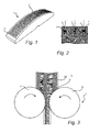
Fig. 1 shows a test device in a perspective view. -
Fig. 2 shows a section through the test device. -
Fig. 3 schematically shows a roller crusher. -
Fig. 4 shows a test arrangement including the test device. -
Fig. 5 shows the test arrangement ofFig. 4 in another position. -
Fig. 6 illustrates a method according to embodiments of the invention. - A test device 1 for a roller crusher comprises a number of pins 2, which extend a
distance 3 from a crushingsurface 4. In this context it may be noted that the test device 1 is equally useful for a roller crusher or a roller grinder or for any type of equipment where materials are crushed, ground or pulverized between two rolls rotating in opposite directions towards each other. The test device may be mounted as part of the crushing surface in a conventional roller crusher or grinder, or it may be part of a specially designed test equipment as is illustrated inFigs 4-5 . - At least one of the pins 2 is connected to a
strain gauge 5, which is arranged to sense the amount of force exerted on the pin or pins 2' which are connected tostrain gauges 5. - As noted above, the crushing
surface 4 may be the crushing surface of a crushingroll 6 in a roller crusher equipment 7. Such a crushing roll is rotatably mounted opposite a similar crushing roll 8 which is arranged to rotate in the opposite direction so that materials M are crushed or pulverized between the rolls and against each other as the materials M enter agap 9 between therolls 6 and 8. As an option, two test devices could be used, one on eachroll 6 and 8. Thecrushing rolls 6, 8 may be part of a roller crusher equipment used as a test arrangement or used for operational crushing or grinding. - It may be noted that the pins 2 are made of a material such as steel which is harder than the crushing
surface 4, which can be made of steel or other metallic or ceramic material. In a roller crusher used for production purposes the pins are placed over the entire crushing surface and then strengthen the crushing surface in two ways. To start with, the materials that are crushed against the crushing surface primarily bear against the pins and not the crushing surface, which means that the crushing surface is not as subjected to the wear and tear of the materials. Secondly, smaller particles in the materials being crushed will get caught between the pins and create a protecting layer of materials on the crushing surface. - The test device can also be part of a sector shaped
roll part 10 which is used for test purposes in a specially designedtest equipment 11 which is shown inFig. 4 and 5 . The crushingsurface 4 is then the crushing surface of the sector shapedroll part 10. This sector shapedroll part 10 is rotatably mounted opposite a similar sector shapedroll part 12 which is rotatable in an opposite direction. The sector shapedroll parts Fig. 4 , to a second position as shown inFig. 5 , as materials M are fed into thegap 9 and crushed between theroll parts - The strain gauges 5 which are connected to the pins 2' will then, during that test session, sense the force which is exerted upon the pins 2' by the materials M. As an option, two test devices could be used, one on each sector shaped
roll part - Regardless of whether the test device is part of a crushing roll or a sector shaped roll part, the output from the
strain gauges 5 can be sent to a data logger which stores the measured strains. These strain values translate into pressure or force values for the pins 2' and the pressure or force values are then analyzed and used for determining a number of parameters describing the interaction between the test device 1 and the materials M being crushed. This information can then be used for classifying the materials M and for efficiently designing a roller crusher equipment for those particular materials, e.g. when selecting a size and power of a motor driving the rotation. The sensed pressure may also be used when determining a design and/or pin material of pins when designing a roll. - The number of pins 2' connected to
strain gauges 5 as well as the positioning of these among the pins 2 in total may be decided based on the axial position on the roll. The materials M being crushed behave differently at the centre of the roll, at the ends of the roll and in positions there between. The influence of feed, distribution, edge effects etc. may thus be studied. - Another option is to arrange a number of pins 2' connected to strain gauges along a line extending across the width of the rolls or roll parts, or in other words transverse to the rotational direction of the rolls. The pressure sensed at these pins may then be used to analyze the pressure changes over the width of the rolls, e.g. in order to analyze the so called "bathtub effect" which is well known in the art. This information may in turn be useful when selecting end plates for the rolls.
- A sensor (not shown) may in addition be arranged for sensing the rotational position of the rolls or roll parts, and the output from this sensor may be combined with the information from the strain gauges in order to determine pressure curves showing how the pressure on the pins 2' changes as the
roll 6 or rollpart 10 is rotated. -
Fig. 6 illustrates a method according to embodiments of the invention. Instep 13, pins are provided in a crushing surface of either a sector shaped roll part in a test equipment for a roller crusher, or in a crushing roll of a roller crusher. - In
step 14 at least one of the pins is connected to a strain gauge. Instep 15 materials are crushed against the crushing surface, as the materials are fed into a gap between two crushing rolls or between two sector shaped roll parts in a test equipment. - Finally, in
step 16, the pressure exerted on the at least one pin which is connected to the strain gauge is sensed by the strain gauge. The sensed or measured strain values can then be saved by a data logging device and be used for analyzing the interaction between the materials and the test device. The strain values may also, as mentioned above, be combined with information on the rotational position of the rolls or roll parts.
Claims (10)
- A test device for a roller crusher of the type which comprises a pair of crushing rolls rotating in opposite directions towards each other for crushing or pulverizing material, the test device (1) having a crushing surface (4) with a number of pins (2) protruding from the crushing surface (4), wherein at leastone of the pins is connected to a strain gauge (5) which is arranged for sensing a pressure exerted on the pin (2') by materials (M) being crushed against the crushing surface (4).
- The test device of claim 1, wherein the crushing surface (4) is a crushing surface of a crushing roll (6) in a roller crusher (7).
- The test device of claim 1, wherein the crushing surface (4) is a crushing surface of a sector shaped roll part (10) used for test purposes.
- The test device of any of claims 2-3, further comprising a sensor for sensing a rotational position of the crushing roll or the sector shaped roll part.
- The test device of any of the preceding claims, wherein a plurality of pins (2') connected to strain gauges (5) are arranged along a line extending across a width of the crushing roll (6) or roll part (10).
- The test device of any of the preceding claims, wherein the strain gauge (5) is connected to a data logging device for storing sensed values from the strain gauge (5).
- A test method for a roller crusher of the type which comprises a pair of crushing rolls rotating in opposite directions towards each other for crushing or pulverizing material, comprising
providing a number of pins (2) protruding from a crushing surface (4),
connecting at least one of the pins (2') to a strain gauge (5),
crushing materials against the crushing surface (4), and
sensing the pressure exerted on the pin (2') connected to the strain gauge (5) by the materials (M) during the crushing. - The method of claim 7, further comprising using the sensed pressure when determining a pressure build-up created by rotation of the rolls.
- The method of any of claims 7-8, further comprising using the sensed pressure when determining characteristics of the materials (M).
- The method of any of claims7-9, further comprising using the sensed pressure when determining a design and/or pin material of pins when designing a roll.
Priority Applications (5)
| Application Number | Priority Date | Filing Date | Title |
|---|---|---|---|
| EP12164956.0A EP2653225A1 (en) | 2012-04-20 | 2012-04-20 | Test device and method for a roller crusher or grinder |
| AU2013205192A AU2013205192A1 (en) | 2012-04-20 | 2013-04-14 | Test device and method for a roller crusher or grinder |
| PCT/IB2013/053097 WO2013156966A1 (en) | 2012-04-20 | 2013-04-19 | Test device and method for a roller crusher or grinder |
| ARP130101299 AR090754A1 (en) | 2012-04-20 | 2013-04-19 | DEVICE AND TEST METHOD FOR A ROLLER CRUSHER OR RECTIFIER |
| CN 201320199472 CN203274989U (en) | 2012-04-20 | 2013-04-19 | Testing device used for roller breaking device or grinding machine |
Applications Claiming Priority (1)
| Application Number | Priority Date | Filing Date | Title |
|---|---|---|---|
| EP12164956.0A EP2653225A1 (en) | 2012-04-20 | 2012-04-20 | Test device and method for a roller crusher or grinder |
Publications (1)
| Publication Number | Publication Date |
|---|---|
| EP2653225A1 true EP2653225A1 (en) | 2013-10-23 |
Family
ID=48536967
Family Applications (1)
| Application Number | Title | Priority Date | Filing Date |
|---|---|---|---|
| EP12164956.0A Withdrawn EP2653225A1 (en) | 2012-04-20 | 2012-04-20 | Test device and method for a roller crusher or grinder |
Country Status (5)
| Country | Link |
|---|---|
| EP (1) | EP2653225A1 (en) |
| CN (1) | CN203274989U (en) |
| AR (1) | AR090754A1 (en) |
| AU (1) | AU2013205192A1 (en) |
| WO (1) | WO2013156966A1 (en) |
Cited By (2)
| Publication number | Priority date | Publication date | Assignee | Title |
|---|---|---|---|---|
| WO2017102736A1 (en) * | 2015-12-14 | 2017-06-22 | Think And Vision Gmbh | Device and method for analyzing drilling mud |
| EP4042137A4 (en) * | 2019-10-04 | 2024-03-13 | Minpraxis Solutions Ltd. | Rock hardness measurement |
Families Citing this family (4)
| Publication number | Priority date | Publication date | Assignee | Title |
|---|---|---|---|---|
| CN107233959A (en) * | 2017-06-21 | 2017-10-10 | 河池市森机械有限责任公司 | Kibbler roll |
| CN108097372A (en) * | 2018-01-30 | 2018-06-01 | 中国矿业大学 | A kind of ring gear adjustable crusher experimental test platform |
| US11802824B2 (en) * | 2020-02-18 | 2023-10-31 | Geopyörä Oy | Test arrangement and method for testing breakage and mechanical properties of rock particles |
| CN112454749A (en) * | 2020-11-06 | 2021-03-09 | 湖南省新基源新材料科技有限公司 | Plastic particle crushing device |
Citations (7)
| Publication number | Priority date | Publication date | Assignee | Title |
|---|---|---|---|---|
| DE2758042A1 (en) * | 1977-12-24 | 1979-06-28 | Peter Voelskow | Bulky scrap crushing and disintegrating machine - uses two interdigitating jaw segments with shredding teeth |
| GB2117268A (en) * | 1982-03-31 | 1983-10-12 | Parry And Associates Limited J | Crushing machinery |
| DE3520929C1 (en) * | 1985-06-07 | 1986-12-11 | Gerhard Dr.-Ing. 1000 Berlin Lechler | Roller |
| US5078327A (en) * | 1987-05-19 | 1992-01-07 | Kemetter Georg L | Device for the processing of materials |
| US5562027A (en) * | 1995-02-16 | 1996-10-08 | Stowe Woodward Licensco, Inc. | Dynamic nip pressure and temperature sensing system |
| DE102007004004A1 (en) * | 2007-01-26 | 2008-07-31 | Polysius Ag | rolling mill |
| US20110259983A1 (en) * | 2010-04-23 | 2011-10-27 | Flsmidth A/S | Wearable Surface For A Device Configured For Material Comminution |
-
2012
- 2012-04-20 EP EP12164956.0A patent/EP2653225A1/en not_active Withdrawn
-
2013
- 2013-04-14 AU AU2013205192A patent/AU2013205192A1/en not_active Abandoned
- 2013-04-19 AR ARP130101299 patent/AR090754A1/en unknown
- 2013-04-19 WO PCT/IB2013/053097 patent/WO2013156966A1/en active Application Filing
- 2013-04-19 CN CN 201320199472 patent/CN203274989U/en not_active Expired - Lifetime
Patent Citations (7)
| Publication number | Priority date | Publication date | Assignee | Title |
|---|---|---|---|---|
| DE2758042A1 (en) * | 1977-12-24 | 1979-06-28 | Peter Voelskow | Bulky scrap crushing and disintegrating machine - uses two interdigitating jaw segments with shredding teeth |
| GB2117268A (en) * | 1982-03-31 | 1983-10-12 | Parry And Associates Limited J | Crushing machinery |
| DE3520929C1 (en) * | 1985-06-07 | 1986-12-11 | Gerhard Dr.-Ing. 1000 Berlin Lechler | Roller |
| US5078327A (en) * | 1987-05-19 | 1992-01-07 | Kemetter Georg L | Device for the processing of materials |
| US5562027A (en) * | 1995-02-16 | 1996-10-08 | Stowe Woodward Licensco, Inc. | Dynamic nip pressure and temperature sensing system |
| DE102007004004A1 (en) * | 2007-01-26 | 2008-07-31 | Polysius Ag | rolling mill |
| US20110259983A1 (en) * | 2010-04-23 | 2011-10-27 | Flsmidth A/S | Wearable Surface For A Device Configured For Material Comminution |
Cited By (2)
| Publication number | Priority date | Publication date | Assignee | Title |
|---|---|---|---|---|
| WO2017102736A1 (en) * | 2015-12-14 | 2017-06-22 | Think And Vision Gmbh | Device and method for analyzing drilling mud |
| EP4042137A4 (en) * | 2019-10-04 | 2024-03-13 | Minpraxis Solutions Ltd. | Rock hardness measurement |
Also Published As
| Publication number | Publication date |
|---|---|
| AU2013205192A1 (en) | 2013-11-07 |
| AR090754A1 (en) | 2014-12-03 |
| CN203274989U (en) | 2013-11-06 |
| WO2013156966A1 (en) | 2013-10-24 |
Similar Documents
| Publication | Publication Date | Title |
|---|---|---|
| EP2653225A1 (en) | Test device and method for a roller crusher or grinder | |
| Morrison et al. | Modelling of incremental rock breakage by impact–for use in DEM models | |
| Rodriguez et al. | Insights into advanced ball mill modelling through discrete element simulations | |
| US20230009484A1 (en) | Rock hardness measurement | |
| CN115335152B (en) | Test device and method for testing fragmentation and mechanical properties of rock particles | |
| AU2013205189B2 (en) | Test device for roller crusher | |
| US20130277467A1 (en) | Test device for roller crusher | |
| Sesemann et al. | A new laboratory test for the estimation of wear in high pressure grinding rolls | |
| Radziszewski et al. | Tumbling mill steel media abrasion wear test development | |
| Mwanga | Test methods for characterising ore comminution behavior in geometallurgy | |
| WO2013156964A1 (en) | Test device for roller crusher | |
| EP3137218B1 (en) | A method and an arrangement for determining a degree of fullness of a large grinding mill drum, and a large grinding mill drum | |
| Voicu et al. | Grinding characteristics of wheat in industrial mills | |
| de Magalhães et al. | Rapid ore breakage parameter estimation from a laboratory crushing test | |
| FI126803B (en) | Method and Arrangement for Determining the Filling Rate of a Large Grinder and a Large Grinder | |
| Ali et al. | A standardised method for the precise quantification of practical minimum comminution energy | |
| Yahyaei et al. | Characterisation of superficial breakage using multi-size pilot mills | |
| JP3991284B1 (en) | Rice grain continuous hardness measuring device | |
| JP5223506B2 (en) | Crushing mill life evaluation method | |
| Ali et al. | Assessing the Precision Rolls Crusher relative to other Laboratory tests | |
| Alatalo | Charge dynamics in tumbling mills: simulation and measurements with an in-mill sensor | |
| Muhayimana et al. | Effects of lifter configuration on power consumption of small scale ball mill | |
| Bergerman et al. | Development of a simplified test for the determination of the Bond Ball Mill Work Index using a modified Hardgrove test | |
| Ali et al. | Assessing comminution circuit performance using precision measurement of size specific energy | |
| Reja et al. | Double impact breakage: Comparison and extension of size specific energy methodology |
Legal Events
| Date | Code | Title | Description |
|---|---|---|---|
| PUAI | Public reference made under article 153(3) epc to a published international application that has entered the european phase |
Free format text: ORIGINAL CODE: 0009012 |
|
| 17P | Request for examination filed |
Effective date: 20130412 |
|
| AK | Designated contracting states |
Kind code of ref document: A1 Designated state(s): AL AT BE BG CH CY CZ DE DK EE ES FI FR GB GR HR HU IE IS IT LI LT LU LV MC MK MT NL NO PL PT RO RS SE SI SK SM TR |
|
| AX | Request for extension of the european patent |
Extension state: BA ME |
|
| 17Q | First examination report despatched |
Effective date: 20141118 |
|
| GRAP | Despatch of communication of intention to grant a patent |
Free format text: ORIGINAL CODE: EPIDOSNIGR1 |
|
| INTG | Intention to grant announced |
Effective date: 20150625 |
|
| STAA | Information on the status of an ep patent application or granted ep patent |
Free format text: STATUS: THE APPLICATION IS DEEMED TO BE WITHDRAWN |
|
| 18D | Application deemed to be withdrawn |
Effective date: 20151103 |