EP2653055B1 - Dispositif de blocage d'une poignée d'une cassette de transport sécurisé - Google Patents
Dispositif de blocage d'une poignée d'une cassette de transport sécurisé Download PDFInfo
- Publication number
- EP2653055B1 EP2653055B1 EP13164136.7A EP13164136A EP2653055B1 EP 2653055 B1 EP2653055 B1 EP 2653055B1 EP 13164136 A EP13164136 A EP 13164136A EP 2653055 B1 EP2653055 B1 EP 2653055B1
- Authority
- EP
- European Patent Office
- Prior art keywords
- transport
- opening
- locking
- internal compartment
- lid
- Prior art date
- Legal status (The legal status is an assumption and is not a legal conclusion. Google has not performed a legal analysis and makes no representation as to the accuracy of the status listed.)
- Not-in-force
Links
- 238000000429 assembly Methods 0.000 description 2
- 230000000712 assembly Effects 0.000 description 2
- 230000000903 blocking effect Effects 0.000 description 2
- 238000000151 deposition Methods 0.000 description 2
- 238000006386 neutralization reaction Methods 0.000 description 2
- 239000007921 spray Substances 0.000 description 2
Images

Classifications
-
- A—HUMAN NECESSITIES
- A45—HAND OR TRAVELLING ARTICLES
- A45C—PURSES; LUGGAGE; HAND CARRIED BAGS
- A45C5/00—Rigid or semi-rigid luggage
- A45C5/03—Suitcases
-
- A—HUMAN NECESSITIES
- A45—HAND OR TRAVELLING ARTICLES
- A45C—PURSES; LUGGAGE; HAND CARRIED BAGS
- A45C13/00—Details; Accessories
- A45C13/18—Devices to prevent theft or loss of purses, luggage or hand carried bags
-
- A—HUMAN NECESSITIES
- A45—HAND OR TRAVELLING ARTICLES
- A45C—PURSES; LUGGAGE; HAND CARRIED BAGS
- A45C13/00—Details; Accessories
- A45C13/26—Special adaptations of handles
- A45C13/28—Combinations of handles with other devices
-
- E—FIXED CONSTRUCTIONS
- E05—LOCKS; KEYS; WINDOW OR DOOR FITTINGS; SAFES
- E05G—SAFES OR STRONG-ROOMS FOR VALUABLES; BANK PROTECTION DEVICES; SAFETY TRANSACTION PARTITIONS
- E05G1/00—Safes or strong-rooms for valuables
- E05G1/005—Portable strong boxes, e.g. which may be fixed to a wall or the like
-
- E—FIXED CONSTRUCTIONS
- E05—LOCKS; KEYS; WINDOW OR DOOR FITTINGS; SAFES
- E05G—SAFES OR STRONG-ROOMS FOR VALUABLES; BANK PROTECTION DEVICES; SAFETY TRANSACTION PARTITIONS
- E05G1/00—Safes or strong-rooms for valuables
- E05G1/02—Details
-
- A—HUMAN NECESSITIES
- A45—HAND OR TRAVELLING ARTICLES
- A45C—PURSES; LUGGAGE; HAND CARRIED BAGS
- A45C5/00—Rigid or semi-rigid luggage
- A45C5/03—Suitcases
- A45C2005/037—Suitcases with a hard shell, i.e. rigid shell as volume creating element
-
- E—FIXED CONSTRUCTIONS
- E05—LOCKS; KEYS; WINDOW OR DOOR FITTINGS; SAFES
- E05G—SAFES OR STRONG-ROOMS FOR VALUABLES; BANK PROTECTION DEVICES; SAFETY TRANSACTION PARTITIONS
- E05G1/00—Safes or strong-rooms for valuables
- E05G1/12—Safes or strong-rooms for valuables with fluent-material releasing, generating or distributing means, e.g. fire-retardant or fire extinguishing means
-
- E—FIXED CONSTRUCTIONS
- E05—LOCKS; KEYS; WINDOW OR DOOR FITTINGS; SAFES
- E05Y—INDEXING SCHEME ASSOCIATED WITH SUBCLASSES E05D AND E05F, RELATING TO CONSTRUCTION ELEMENTS, ELECTRIC CONTROL, POWER SUPPLY, POWER SIGNAL OR TRANSMISSION, USER INTERFACES, MOUNTING OR COUPLING, DETAILS, ACCESSORIES, AUXILIARY OPERATIONS NOT OTHERWISE PROVIDED FOR, APPLICATION THEREOF
- E05Y2201/00—Constructional elements; Accessories therefor
- E05Y2201/60—Suspension or transmission members; Accessories therefor
- E05Y2201/622—Suspension or transmission members elements
- E05Y2201/676—Transmission of human force
- E05Y2201/68—Handles, cranks
Definitions
- the present invention relates to a carrier handle locking device of a cassette (or container) for securely storing and transporting valuables in bulk or in bags.
- the invention also relates to a cassette provided with such a transport handle locking device.
- cassette or container
- This type of secured cassette most often includes an opening closed by a movable cover, this opening for depositing inside the container the tickets to be transported.
- one or more neutralization modules are arranged inside the container, each of these modules consisting of a chamber filled for example with ink and connected to a spray boom, and means for driving the container. ink from the chamber to the spray boom in case of fracturing of the enclosure of the container or following a remote control.
- US5176281 discloses a cassette with a lid and a pivoting handle.
- the purpose of the present invention is to provide a cassette carrying handle locking device for securely storing and transporting valuables in bulk or in bags being reliable and making the port and / or or the transport of said cassette less easy or impossible when the lid of said cassette is open.
- the device makes it possible to prevent a thieving candidate from grabbing the cassette by the handle and transporting it without being noticed; this deters the theft of the cassette and also reduces internal fraud within the banking and CIT companies.
- the subject of the present invention is a device for blocking a handle for transporting a cassette for storing and securely transporting valuables, in particular banknotes in bulk or housed in bags, comprising at least one internal compartment arranged to contain said values and having an opening of generally rectangular shape, a lid disposed at the opening and articulated around one of the longitudinal edges of said opening to allow access to the interior the inner compartment and a carrying handle pivotable relative to said inner compartment, by means of two arms and two axes each pivoted on one of the side walls of the inner compartment about an axis substantially parallel to the hinge axis of said cover, said transport handle being able to pivot between a "transport” position in which its arms are substantially d in the longitudinal plane of the internal compartment containing the pivot axis of said transport handle and an "opening" position in which, on the one hand, its arms are substantially in a plane perpendicular to said longitudinal plane of the inner compartment and, on the other hand, the lid can then be opened.
- Said locking device is remarkable in that it is of the mechanical snap type and allows, on the one hand, when the lid is closed to release the transport handle that can pivot between its "transport” and “opening” positions and on the other hand, when the lid begins to open, to lock the transport handle in the "open” position.
- the locking device comprises at least one wheel fixed on one of the axes and having a notch, an arm articulated to the inner compartment about an axis substantially parallel to the axis of rotation of the carrying handle and having at one of its ends a bearing zone and at the other end a flange adapted to cooperate with said notch, a pin secured to the lid and adapted to cooperate with said bearing zone to pivot said arm, and a return member fixed between said arm and the side wall of the inner compartment, said arm being able to pivot between a "locking" position in which the flange is engaged in the notch of the wheel and a "free” position in which the rim is clear of the notch of the wheel.
- the return member exerts a restoring force tending to bring the arm into its "locking" position.
- the return member is advantageously a spring.
- the wheel comprises at least one light capable of cooperating with an axis fixed perpendicular to the side wall of the internal compartment to limit the rotation of the carrying handle between its "transport” and “transport” positions. "opening".
- the locking device comprises two wheel-arm-tenon-return member assemblies, each wheel-arm-pin-return member assembly being associated with one of the arms of the carrying handle.
- the invention also relates to a cassette intended to be used for the secure transport of valuables
- a cassette intended to be used for the secure transport of valuables
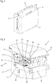
- the cassette 1 for the storage and secure transport of valuables, in particular of banknotes in bulk or housed in bags comprises an internal compartment 2 arranged to contain said values and having an opening 3 of generally rectangular shape allowing depositing said values inside said inner compartment 2, an outer envelope 4 surrounding said inner compartment 2, a cover 5 disposed in line with the opening 3 hinged around one of the longitudinal edges of said opening 3 to allow accessing the interior of the inner compartment 2 and a hinged transport handle 6, via two arms 7, to said inner compartment 2 about an axis substantially parallel to the axis of rotation of said cover 5.
- the carrying handle 6 is pivotable between a "transport” position in which its arms 7 are substantially in the longitudinal plane of the inner compartment 2 and an “opening" position in which its arms 7 are substantially in a plane perpendicular to the longitudinal plane of the inner compartment 2.
- the carrying handle 6 and its arms 7 are dimensioned so that the lid 5 can open only when the carrying handle 6 is in abutment position "opening".
- each arm 7 is integral with an axis 8 pivotally mounted on one of side walls 9 of the inner compartment 2.
- the locking device 10 of the carrying handle 6 comprises at least one wheel 11 fixed on one of the pins 8 and having a notch 12, an arm 13 hinged to the inner compartment 2 about an axis substantially parallel to the axis rotation of the carrying handle 6 and having at one of its ends a bearing zone 14 and at the other end a flange 15 adapted to cooperate with said notch 12, a pin 16 secured to the cover 5 and adapted to cooperate with said bearing zone 14 to pivot said arm 13, and a return member (not shown in the figures) fixed between said arm 13 and the side wall 9 of the inner compartment 2.
- the arm 13 is pivotable between a "lock” position in which the carrying handle 6 is locked in abutment position "opening” and a “free” position in which the carrying handle 6 is free to pivot between its positions "transport” and “opening".
- the return member which is preferably a spring, exerts a restoring force tending to bring the arm 13 back into its "locking" position.
- the locking device 10 blocks the transport handle 6 in the "open” position and, when the cover 5 is closed, the transport handle 6 is free to pivot between its "transport” positions. and "opening".
- the handle locking device is particularly effective since from a very small opening angle of the lid 5, less than one degree, the handle lock 6 is active.
- the wheel 11 comprises at least one slot 17 adapted to cooperate with an axis 18 fixed perpendicular to the side wall 9 of the inner compartment 2 to limit the rotation of the carrying handle 6 between its "transport” and “opening” positions.
- the locking device 10 comprises two wheel assemblies 11-arm 13-pin 16-return member, each wheel assembly 11-arm 13-pin 16-return member being associated with one of the arms 7 of the carrying handle 6.
- the locking device 10 may include electrical components such as, for example, micromotors or electromagnets, to lock and release the carrying handle 6, without departing from the scope of the present invention.
- the locking device 10 of the mechanical latching type comprising at least one wheel assembly 11-arm 13-pin 16-return member, is simpler to achieve and less prone to failures. Moreover, this type of blocking device 10 does not require an additional source of energy to activate or deactivate them.
- the locking device 10 of the carrying handle 6 of a cassette 1 is mainly intended to be used for the secure transport of valuables, in particular loose bank notes or housed in bags, but it can also be used for the transport of sensitive or dangerous products.
Landscapes
- Purses, Travelling Bags, Baskets, Or Suitcases (AREA)
Description
- La présente invention concerne un dispositif de blocage de poignée de transport d'une cassette (ou container) servant à stocker et transporter de manière sécurisée des objets de valeur disposés en vrac ou dans des sacs. L'invention concerne également une cassette munie d'un tel dispositif de blocage de poignée de transport.
- De façon connue, le stockage et le transport sécurisé d'objets de valeur, notamment de billets de banque en vrac ou logés dans des sacs, se fait par l'intermédiaire d'une cassette (ou container) que l'on peut déplacer manuellement. Ce type de cassette sécurisée comprend le plus souvent une ouverture fermée par un couvercle mobile, cette ouverture permettant de déposer à l'intérieur du container les billets à transporter.
- En cas de tentative de vol ou d'ouverture par effraction du container, il est généralement prévu de neutraliser les billets notamment par maculage. A cet effet, un ou plusieurs modules de neutralisation sont disposés à l'intérieur du container, chacun de ces modules se composant d'une chambre remplie par exemple d'encre et connectée à une rampe d'aspersion, et de moyens pour chasser l'encre de la chambre vers la rampe d'aspersion en cas de fracturation de l'enceinte du container ou suite à une commande à distance.
- C'est pourquoi afin d'éviter la neutralisation des valeurs contenues dans la cassette, certains voleurs attendent que les employés de banque ouvrent normalement le couvercle de la cassette pour s'emparer de la cassette et s'enfuir en prenant soin de ne pas refermer ledit couvercle.
- Par exemple,
US5176281 divulgue une cassette avec un couvercle et une poignée pivotante. - Ainsi, le but de la présente invention est de proposer un dispositif de blocage de poignée de transport d'une cassette servant à stocker et transporter de manière sécurisée des objets de valeur disposés en vrac ou dans des sacs étant fiable et rendant le port et/ou le transport de ladite cassette moins aisé voire impossible lorsque le couvercle de ladite cassette est ouvert. En outre, le dispositif permet d'éviter qu'un candidat voleur ne puisse se saisir de la cassette par la poignée et la transporter sans être remarqué ; ceci dissuade le vol de la cassette et réduit aussi les fraudes internes au sein des sociétés bancaires et de transport de fonds.
- A cet effet, la présente invention a pour objet un dispositif de blocage d'une poignée de transport d'une cassette de stockage et de transport sécurisé d'objets de valeur, notamment de billets de banque en vrac ou logés dans des sacs, comportant au moins un compartiment interne agencé pour contenir lesdites valeurs et présentant une ouverture de forme globalement rectangulaire, un couvercle disposé au droit de l'ouverture et articulé autour de l'un des bords longitudinaux de ladite ouverture pour permettre d'accéder à l'intérieur du compartiment interne et une poignée de transport apte à pivoter par rapport audit compartiment interne, par l'intermédiaire de deux bras et de deux axes montés chacun pivotant sur l'une des parois latérales du compartiment interne autour d'un axe sensiblement parallèle à l'axe d'articulation dudit couvercle, ladite poignée de transport étant apte à pivoter entre une position "transport" dans laquelle ses bras se trouvent sensiblement dans le plan longitudinal du compartiment interne contenant l'axe de pivotement de ladite poignée de transport et une position "ouverture" dans laquelle, d'une part, ses bras se trouvent sensiblement dans un plan perpendiculaire audit plan longitudinal du compartiment interne et, d'autre part, le couvercle peut alors être ouvert. Ledit dispositif de blocage est remarquable en ce qu'il est du type mécanique à encliquetage et permet, d'une part, lorsque le couvercle est fermé de libérer la poignée de transport qui peut pivoter entre ses positions "transport" et "ouverture" et, d'autre part, lorsque le couvercle commence à s'ouvrir, de bloquer la poignée de transport en position "ouverture".
- De manière avantageuse, le dispositif de blocage selon comporte au moins une roue fixée sur l'un des axes et présentant un cran, un bras articulé au compartiment interne autour d'un axe sensiblement parallèle à l'axe de rotation de la poignée de transport et comportant à l'une de ses extrémités une zone d'appui et à l'autre extrémité un rebord apte à coopérer avec ledit cran, un tenon solidaire du couvercle et apte à coopérer avec ladite zone d'appui pour faire pivoter ledit bras, et un organe de rappel fixé entre ledit bras et la paroi latérale du compartiment interne, ledit bras étant apte à pivoter entre une position "blocage" dans laquelle le rebord est engagé dans le cran de la roue et une position "libre" dans laquelle le rebord est dégagé du cran de la roue.
- De préférence, l'organe de rappel exerce une force de rappel tendant à ramener le bras dans sa position "blocage". L'organe de rappel est avantageusement un ressort.
- La roue comporte au moins une lumière apte à coopérer avec un axe fixé perpendiculairement à la paroi latérale du compartiment interne pour limiter la rotation de la poignée de transport entre ses positions "transport" et "ouverture".
- Selon un mode préféré, le dispositif de blocage comporte deux ensembles roue-bras-tenon-organe de rappel, chaque ensemble roue-bras-tenon-organe de rappel étant associé à l'un des bras de la poignée de transport.
- L'invention concerne également une cassette destinée à être utilisée pour le transport sécurisé d'objets de valeur comportant au moins un compartiment interne agencé pour contenir lesdites valeurs et présentant une ouverture de forme globalement rectangulaire, un couvercle disposé au droit de l'ouverture et articulé autour de l'un des bords longitudinaux de ladite ouverture pour permettre d'accéder à l'intérieur du compartiment interne et une poignée de transport apte à pivoter, par l'intermédiaire de deux bras et de deux axes, par rapport audit compartiment interne autour d'un axe sensiblement parallèle à l'axe de rotation dudit couvercle, ladite poignée de transport étant apte à pivoter entre une position "transport" et une position "ouverture"; ladite cassette est remarquable en ce qu'elle comporte un dispositif de blocage de poignée de transport selon l'invention.
- D'autres avantages et caractéristiques ressortiront mieux de la description qui va suivre d'une variante d'exécution d'un dispositif de blocage de poignée de transport selon l'invention en référence aux figures annexées sur lesquelles :
- la
figure 1 est une vue de perspective d'une cassette de transport sécurisé muni du dispositif de blocage de poignée de transport selon l'invention ; - la
figure 2 est une vue de détail de la cassette de lafigure 1 sans son enveloppe externe avec sa poignée en position "ouverture" libre et son couvercle fermé ; - la
figure 3 est une vue de détail de la cassette de lafigure 1 sans son enveloppe externe avec sa poignée en position "ouverture" bloquée et son couvercle ouvert. - En référence aux
figures 1 à 3 , la cassette 1 pour le stockage et le transport sécurisé d'objets de valeur, notamment de billets de banque en vrac ou logés dans des sacs, comprend un compartiment interne 2 agencé pour contenir lesdites valeurs et présentant une ouverture 3 de forme globalement rectangulaire permettant de déposer lesdites valeurs à l'intérieur dudit compartiment interne 2, une enveloppe externe 4 entourant ledit compartiment interne 2, un couvercle 5 disposé au droit de l'ouverture 3 articulé autour de l'un des bords longitudinaux de ladite ouverture 3 pour permettre d'accéder à l'intérieur du compartiment interne 2 et une poignée de transport 6 articulée, par l'intermédiaire de deux bras 7, audit compartiment interne 2 autour d'un axe sensiblement parallèle à l'axe de rotation dudit couvercle 5. - La poignée de transport 6 est apte à pivoter entre une position "transport" dans laquelle ses bras 7 se trouvent sensiblement dans le plan longitudinal du compartiment interne 2 et une position "ouverture" dans laquelle ses bras 7 se trouvent sensiblement dans un plan perpendiculaire au plan longitudinal du compartiment interne 2. La poignée de transport 6 et ses bras 7 sont dimensionnés de sorte que le couvercle 5 ne puisse s'ouvrir que lorsque la poignée de transport 6 se trouve en butée en position "ouverture".
- En référence à la
figure 2 , pour réaliser l'articulation de la poignée de transport 6, chaque bras 7 est solidaire d'un axe 8 monté pivotant sur l'une des parois latérales 9 du compartiment interne 2. - Le dispositif de blocage 10 de la poignée de transport 6 comprend au moins une roue 11 fixée sur l'un des axes 8 et présentant un cran 12, un bras 13 articulé au compartiment interne 2 autour d'un axe sensiblement parallèle à l'axe de rotation de la poignée de transport 6 et comportant à l'une de ses extrémités une zone d'appui 14 et à l'autre extrémité un rebord 15 apte à coopérer avec ledit cran 12, un tenon 16 solidaire du couvercle 5 et apte à coopérer avec ladite zone d'appui 14 pour faire pivoter ledit bras 13, et un organe de rappel (non représenté sur les figures) fixé entre ledit bras 13 et la paroi latérale 9 du compartiment interne 2.
- Le bras 13 est apte à pivoter entre une position "blocage" dans laquelle la poignée de transport 6 se trouve bloquée en butée en position "ouverture" et une position "libre" dans laquelle la poignée de transport 6 est libre de pivoter entre ses positions "transport" et "ouverture".
- L'organe de rappel, qui est de préférence un ressort, exerce une force de rappel tendant à ramener le bras 13 dans sa position "blocage".
- Lorsque le couvercle 5 commence à s'ouvrir, le dispositif de blocage 10 bloque la poignée de transport 6 en position "ouverture" et, lorsque le couvercle 5 est fermé, la poignée de transport 6 est libre de pivoter entre ses positions "transport" et "ouverture".
- Pour ce faire, lorsque le couvercle 5 est fermé, le tenon 16 est en contact avec la zone d'appui 14 du bras 13 et maintient le bras 13 dans sa position "libre" dans laquelle le rebord 15 est dégagé du cran 12 de la roue 11 et afin de libérer la rotation de cette dernière et donc la rotation de l'axe 8 et de la poignée de transport 6. En revanche, lorsque la poignée de transport 6 est en position "ouverture" et que le couvercle 5 commence à s'ouvrir, le tenon 16 se déplace jusqu'à ne plus être en contact avec la zone d'appui 14 du bras 13 qui est ramené sous l'action de l'organe de rappel vers sa position "blocage" dans laquelle le rebord 15 est engagé dans le cran 12 de la roue 11 et pour bloquer la rotation de cette dernière et donc maintenir la poignée de transport 6 dans sa position "ouverture".
- Le dispositif de blocage de poignée est particulièrement efficace puisqu'à partir d'un angle d'ouverture du couvercle 5 très faible, moins d'un degré, le blocage de poignée de transport 6 est actif.
- La roue 11 comporte au moins une lumière 17 apte à coopérer avec un axe 18 fixé perpendiculairement à la paroi latérale 9 du compartiment interne 2 pour limiter la rotation de la poignée de transport 6 entre ses positions "transport" et "ouverture".
- Selon un mode de réalisation préféré, le dispositif de blocage 10 comporte deux ensembles roue 11-bras 13-tenon 16-organe de rappel, chaque ensemble roue 11-bras 13-tenon 16-organe de rappel étant associé à l'un des bras 7 de la poignée de transport 6.
- Le dispositif de blocage 10 pourra comporter des organes électriques tels que, par exemple, des micromoteurs ou encore des électro-aimants, pour bloquer et libérer la poignée de transport 6, sans sortir du cadre de la présente invention.
- Toutefois, le dispositif de blocage 10 du type mécanique à encliquetage, comportant au moins un ensemble roue 11-bras 13-tenon 16-organe de rappel, est plus simple à réaliser et moins sujet à des pannes. Par ailleurs, ce type de dispositif de blocage 10 ne nécessite pas de source d'énergie supplémentaire pour les activer ou désactiver.
- Enfin, on comprend bien que lorsque le couvercle 5 est ouvert et que la poignée de transport 6 est bloquée en position "ouverture", le port et le transport de la cassette 1 est rendu difficile voire impossible car ladite poignée de transport 6 et ses bras 7 se trouvent orienter perpendiculairement au plan longitudinal du compartiment interne 2. Un voleur qui s'emparerait de la cassette 1 dans cette configuration ne passerait sûrement pas inaperçu.
- Comme décrit précédemment, le dispositif de blocage 10 de poignée de transport 6 d'une cassette 1 selon l'invention est principalement destiné à être utilisé pour le transport sécurisé d'objets de valeur, notamment de billets de banque en vrac ou logés dans des sacs, mais il peut également être utilisé pour le transport de produits sensibles ou dangereux.
- Enfin, il est clair que la présente invention ne se limite pas aux seules formes d'exécution de ces dispositifs de blocage 10 et cassette 1; elle en embrasse, au contraire, toutes les variantes de réalisation et d'application respectant le même principe.
Claims (7)
- Dispositif de blocage (10) d'une poignée de transport (6) d'une cassette (1) de stockage et de transport sécurisé d'objets de valeur, notamment de billets de banque en vrac ou logés dans des sacs, comportant au moins un compartiment interne (2) agencé pour contenir lesdites valeurs et présentant une ouverture (3) de forme globalement rectangulaire, un couvercle (5) disposé au droit de l'ouverture (3) et articulé autour de l'un des bords longitudinaux de ladite ouverture (3) pour permettre d'accéder à l'intérieur du compartiment interne (2) et une poignée de transport (6) apte à pivoter par rapport audit compartiment interne (2), par l'intermédiaire de deux bras (7) et de deux axes (8) montés chacun pivotant sur l'une des parois latérales (9) du compartiment interne (2), autour d'un axe sensiblement parallèle à l'axe d'articulation dudit couvercle (5), ladite poignée de transport (6) étant apte à pivoter entre une position "transport" dans laquelle ses bras (7) se trouvent sensiblement dans le plan longitudinal du compartiment interne (2) contenant l'axe de pivotement de ladite poignée de transport (6) et une position "ouverture" dans laquelle, d'une part, ses bras (7) se trouvent sensiblement dans un plan perpendiculaire audit plan longitudinal du compartiment interne (2) et, d'autre part, le couvercle (5) peut alors être ouvert, ledit dispositif de blocage (10) étant tel qu'il est du type mécanique à encliquetage et permet, lorsque le couvercle (5) est fermé de libérer la poignée de transport (6) qui peut pivoter entre ses positions "transport" et "ouverture" et caractérisé en ce que lorsque le couvercle (5) commence à s'ouvrir, permet de bloquer la poignée de transport (6) en position "ouverture".
- Dispositif de blocage (10) selon la revendication 1 caractérisé en ce qu'il comporte au moins une roue (11) fixée sur l'un des axes 8 et présentant un cran (12), un bras (13) articulé au compartiment interne (2) autour d'un axe sensiblement parallèle à l'axe de rotation de la poignée de transport (6) et comportant à l'une de ses extrémités une zone d'appui (14) et à l'autre extrémité un rebord (15) apte à coopérer avec ledit cran (12), un tenon (16) solidaire du couvercle (5) et apte à coopérer avec ladite zone d'appui (14) pour faire pivoter ledit bras (13), et un organe de rappel fixé entre ledit bras (13) et la paroi latérale (9) du compartiment interne (2), ledit bras (13) étant apte à pivoter entre une position "blocage" dans laquelle le rebord (15) est engagé dans le cran (12) de la roue (11) et une position "libre" dans laquelle le rebord (15) est dégagé du cran (12) de la roue (11).
- Dispositif de blocage (10) selon la revendication 2 caractérisé en ce que l'organe de rappel exerce une force de rappel tendant à ramener le bras (13) dans sa position "blocage".
- Dispositif de blocage (10) selon la revendication 3 caractérisé en ce que l'organe de rappel est un ressort.
- Dispositif de blocage (10) selon l'une quelconque des revendications 2 à 4 caractérisé en ce que la roue (11) comporte au moins une lumière (17) apte à coopérer avec un axe (18) fixé perpendiculairement à la paroi latérale (9) du compartiment interne (2) pour limiter la rotation de la poignée de transport (6) entre ses positions "transport" et "ouverture"
- Dispositif de blocage (10) selon l'une quelconque des revendications 2 à 5 caractérisé en ce qu'il comporte deux ensembles roue (11)-bras (13)-tenon (16)-organe de rappel, chaque ensemble roue (11)-bras (13)-tenon (16)-organe de rappel étant associé à l'un des bras (7) de la poignée de transport (6).
- Cassette (1) destinée à être utilisée pour le transport sécurisé d'objets de valeur comportant au moins un compartiment interne (2) agencé pour contenir lesdites valeurs et présentant une ouverture (3) de forme globalement rectangulaire, un couvercle (5) disposé au droit de l'ouverture (3) et articulé autour de l'un des bords longitudinaux de ladite ouverture (3) pour permettre d'accéder à l'intérieur du compartiment interne (2) et une poignée de transport (6) apte à pivoter, par l'intermédiaire de deux bras (7) et de deux axes (8), par rapport audit compartiment interne (2) autour d'un axe sensiblement parallèle à l'axe de rotation dudit couvercle (5), ladite poignée de transport (6) étant apte à pivoter entre une position "transport" et une position "ouverture", ladite cassette (1) étant caractérisée en ce qu'elle comporte un dispositif de blocage (10) de poignée de transport (6) selon l'une quelconque des revendications 1 à 6.
Applications Claiming Priority (1)
| Application Number | Priority Date | Filing Date | Title |
|---|---|---|---|
| FR1253613A FR2989562B1 (fr) | 2012-04-19 | 2012-04-19 | Dispositif de blocage d'une poignee d'une cassette de transport securise |
Publications (2)
| Publication Number | Publication Date |
|---|---|
| EP2653055A1 EP2653055A1 (fr) | 2013-10-23 |
| EP2653055B1 true EP2653055B1 (fr) | 2018-07-18 |
Family
ID=48087476
Family Applications (1)
| Application Number | Title | Priority Date | Filing Date |
|---|---|---|---|
| EP13164136.7A Not-in-force EP2653055B1 (fr) | 2012-04-19 | 2013-04-17 | Dispositif de blocage d'une poignée d'une cassette de transport sécurisé |
Country Status (2)
| Country | Link |
|---|---|
| EP (1) | EP2653055B1 (fr) |
| FR (1) | FR2989562B1 (fr) |
Citations (1)
| Publication number | Priority date | Publication date | Assignee | Title |
|---|---|---|---|---|
| EP0398433A1 (fr) * | 1989-05-18 | 1990-11-22 | Curver Rubbermaid B.V. | Récipient muni d'un couvercle verrouillable |
Family Cites Families (2)
| Publication number | Priority date | Publication date | Assignee | Title |
|---|---|---|---|---|
| US5176281A (en) * | 1991-09-20 | 1993-01-05 | Woodstream Corporation | Tackle box with lid-latching handle and removable carrying case |
| US7246718B2 (en) * | 2003-10-02 | 2007-07-24 | Zag Industries Ltd. | Toolbox with handle having cover locking mechanism |
-
2012
- 2012-04-19 FR FR1253613A patent/FR2989562B1/fr not_active Expired - Fee Related
-
2013
- 2013-04-17 EP EP13164136.7A patent/EP2653055B1/fr not_active Not-in-force
Patent Citations (1)
| Publication number | Priority date | Publication date | Assignee | Title |
|---|---|---|---|---|
| EP0398433A1 (fr) * | 1989-05-18 | 1990-11-22 | Curver Rubbermaid B.V. | Récipient muni d'un couvercle verrouillable |
Also Published As
| Publication number | Publication date |
|---|---|
| FR2989562B1 (fr) | 2014-11-14 |
| FR2989562A1 (fr) | 2013-10-25 |
| EP2653055A1 (fr) | 2013-10-23 |
Similar Documents
| Publication | Publication Date | Title |
|---|---|---|
| EP3393294B1 (fr) | Bagage muni d'un dispositif de verrouillage de fermeture à glissière | |
| FR2893345A1 (fr) | Cadenas commande par une cle et muni d'un indicateur visuel | |
| EP3245914A1 (fr) | Systeme d'ouverture et de fermeture pour autocuiseur | |
| EP0168279B1 (fr) | Coffret, en particulier pour compteur électrique ou analogue | |
| FR2553980A1 (fr) | Mecanisme de verrouillage pour valise | |
| FR2510965A3 (fr) | Dispositif pour fixer un element amovible au corps d'un vehicule a moteur a deux roues | |
| EP4176756B1 (fr) | Insert pour un bracelet de montre | |
| WO2022023149A1 (fr) | Colis pliable pourvu de moyens de colis pliable pourvu de moyens de verrouillage | |
| EP2653055A1 (fr) | Dispositif de blocage d'une poignée d'une cassette de transport sécurisé | |
| EP3556263A1 (fr) | Boîte comprenant un dispositif de maintien en position d'un composant horloger | |
| CA2572368A1 (fr) | Procede de transport securise de documents ou d'objets de valeur et caissette utilisable lors de la mise en oeuvre dudit procede | |
| EP0539300B1 (fr) | Dispositif de fermeture de porte d'enceintes isolées. | |
| EP3491327A1 (fr) | Dispositif de blocage d'un obus et civière comportant un tel dispositif de blocage | |
| FR2650566A1 (fr) | Emballage rigide de securite pour le transport et le stockage de valeurs | |
| FR2500878A1 (fr) | Systeme de ceinture antivol pour bagages | |
| EP3738463B1 (fr) | Valise de collecte avec double porte | |
| EP2230372B1 (fr) | Sas de sécurité | |
| WO2025262027A1 (fr) | Dispositif de déclipsage d'un ouvrant par rotation contre un dormant | |
| FR3163356A1 (fr) | Dispositif de déclipsage d’un ouvrant par rotation contre un dormant | |
| FR2743841A1 (fr) | Coffre de protection d'objets | |
| FR3145153A1 (fr) | Élément de stockage d’objets sécurisé | |
| EP3324377B1 (fr) | Dispositif de court-circuit pour système securisé | |
| FR3073963A1 (fr) | Piege a cambrioleurs | |
| WO2001075829A1 (fr) | Dispositif d'alarme pour la protection d'un conteneur contre une intrusion | |
| EP0555108A1 (fr) | Dispositif antivol pour porte de véhicule utilitaire ou de conteneur |
Legal Events
| Date | Code | Title | Description |
|---|---|---|---|
| PUAI | Public reference made under article 153(3) epc to a published international application that has entered the european phase |
Free format text: ORIGINAL CODE: 0009012 |
|
| AK | Designated contracting states |
Kind code of ref document: A1 Designated state(s): AL AT BE BG CH CY CZ DE DK EE ES FI FR GB GR HR HU IE IS IT LI LT LU LV MC MK MT NL NO PL PT RO RS SE SI SK SM TR |
|
| AX | Request for extension of the european patent |
Extension state: BA ME |
|
| 17P | Request for examination filed |
Effective date: 20140204 |
|
| RBV | Designated contracting states (corrected) |
Designated state(s): AL AT BE BG CH CY CZ DE DK EE ES FI FR GB GR HR HU IE IS IT LI LT LU LV MC MK MT NL NO PL PT RO RS SE SI SK SM TR |
|
| GRAP | Despatch of communication of intention to grant a patent |
Free format text: ORIGINAL CODE: EPIDOSNIGR1 |
|
| STAA | Information on the status of an ep patent application or granted ep patent |
Free format text: STATUS: GRANT OF PATENT IS INTENDED |
|
| INTG | Intention to grant announced |
Effective date: 20180410 |
|
| GRAS | Grant fee paid |
Free format text: ORIGINAL CODE: EPIDOSNIGR3 |
|
| GRAA | (expected) grant |
Free format text: ORIGINAL CODE: 0009210 |
|
| STAA | Information on the status of an ep patent application or granted ep patent |
Free format text: STATUS: THE PATENT HAS BEEN GRANTED |
|
| AK | Designated contracting states |
Kind code of ref document: B1 Designated state(s): AL AT BE BG CH CY CZ DE DK EE ES FI FR GB GR HR HU IE IS IT LI LT LU LV MC MK MT NL NO PL PT RO RS SE SI SK SM TR |
|
| REG | Reference to a national code |
Ref country code: GB Ref legal event code: FG4D Free format text: NOT ENGLISH |
|
| REG | Reference to a national code |
Ref country code: CH Ref legal event code: EP |
|
| REG | Reference to a national code |
Ref country code: IE Ref legal event code: FG4D Free format text: LANGUAGE OF EP DOCUMENT: FRENCH |
|
| REG | Reference to a national code |
Ref country code: AT Ref legal event code: REF Ref document number: 1018424 Country of ref document: AT Kind code of ref document: T Effective date: 20180815 |
|
| REG | Reference to a national code |
Ref country code: DE Ref legal event code: R096 Ref document number: 602013040340 Country of ref document: DE |
|
| REG | Reference to a national code |
Ref country code: NL Ref legal event code: MP Effective date: 20180718 |
|
| REG | Reference to a national code |
Ref country code: LT Ref legal event code: MG4D |
|
| REG | Reference to a national code |
Ref country code: AT Ref legal event code: MK05 Ref document number: 1018424 Country of ref document: AT Kind code of ref document: T Effective date: 20180718 |
|
| PG25 | Lapsed in a contracting state [announced via postgrant information from national office to epo] |
Ref country code: NL Free format text: LAPSE BECAUSE OF FAILURE TO SUBMIT A TRANSLATION OF THE DESCRIPTION OR TO PAY THE FEE WITHIN THE PRESCRIBED TIME-LIMIT Effective date: 20180718 |
|
| PG25 | Lapsed in a contracting state [announced via postgrant information from national office to epo] |
Ref country code: BG Free format text: LAPSE BECAUSE OF FAILURE TO SUBMIT A TRANSLATION OF THE DESCRIPTION OR TO PAY THE FEE WITHIN THE PRESCRIBED TIME-LIMIT Effective date: 20181018 Ref country code: RS Free format text: LAPSE BECAUSE OF FAILURE TO SUBMIT A TRANSLATION OF THE DESCRIPTION OR TO PAY THE FEE WITHIN THE PRESCRIBED TIME-LIMIT Effective date: 20180718 Ref country code: IS Free format text: LAPSE BECAUSE OF FAILURE TO SUBMIT A TRANSLATION OF THE DESCRIPTION OR TO PAY THE FEE WITHIN THE PRESCRIBED TIME-LIMIT Effective date: 20181118 Ref country code: AT Free format text: LAPSE BECAUSE OF FAILURE TO SUBMIT A TRANSLATION OF THE DESCRIPTION OR TO PAY THE FEE WITHIN THE PRESCRIBED TIME-LIMIT Effective date: 20180718 Ref country code: LT Free format text: LAPSE BECAUSE OF FAILURE TO SUBMIT A TRANSLATION OF THE DESCRIPTION OR TO PAY THE FEE WITHIN THE PRESCRIBED TIME-LIMIT Effective date: 20180718 Ref country code: PL Free format text: LAPSE BECAUSE OF FAILURE TO SUBMIT A TRANSLATION OF THE DESCRIPTION OR TO PAY THE FEE WITHIN THE PRESCRIBED TIME-LIMIT Effective date: 20180718 Ref country code: NO Free format text: LAPSE BECAUSE OF FAILURE TO SUBMIT A TRANSLATION OF THE DESCRIPTION OR TO PAY THE FEE WITHIN THE PRESCRIBED TIME-LIMIT Effective date: 20181018 Ref country code: FI Free format text: LAPSE BECAUSE OF FAILURE TO SUBMIT A TRANSLATION OF THE DESCRIPTION OR TO PAY THE FEE WITHIN THE PRESCRIBED TIME-LIMIT Effective date: 20180718 Ref country code: GR Free format text: LAPSE BECAUSE OF FAILURE TO SUBMIT A TRANSLATION OF THE DESCRIPTION OR TO PAY THE FEE WITHIN THE PRESCRIBED TIME-LIMIT Effective date: 20181019 Ref country code: SE Free format text: LAPSE BECAUSE OF FAILURE TO SUBMIT A TRANSLATION OF THE DESCRIPTION OR TO PAY THE FEE WITHIN THE PRESCRIBED TIME-LIMIT Effective date: 20180718 |
|
| PG25 | Lapsed in a contracting state [announced via postgrant information from national office to epo] |
Ref country code: LV Free format text: LAPSE BECAUSE OF FAILURE TO SUBMIT A TRANSLATION OF THE DESCRIPTION OR TO PAY THE FEE WITHIN THE PRESCRIBED TIME-LIMIT Effective date: 20180718 Ref country code: AL Free format text: LAPSE BECAUSE OF FAILURE TO SUBMIT A TRANSLATION OF THE DESCRIPTION OR TO PAY THE FEE WITHIN THE PRESCRIBED TIME-LIMIT Effective date: 20180718 Ref country code: HR Free format text: LAPSE BECAUSE OF FAILURE TO SUBMIT A TRANSLATION OF THE DESCRIPTION OR TO PAY THE FEE WITHIN THE PRESCRIBED TIME-LIMIT Effective date: 20180718 |
|
| REG | Reference to a national code |
Ref country code: DE Ref legal event code: R097 Ref document number: 602013040340 Country of ref document: DE |
|
| PG25 | Lapsed in a contracting state [announced via postgrant information from national office to epo] |
Ref country code: EE Free format text: LAPSE BECAUSE OF FAILURE TO SUBMIT A TRANSLATION OF THE DESCRIPTION OR TO PAY THE FEE WITHIN THE PRESCRIBED TIME-LIMIT Effective date: 20180718 Ref country code: IT Free format text: LAPSE BECAUSE OF FAILURE TO SUBMIT A TRANSLATION OF THE DESCRIPTION OR TO PAY THE FEE WITHIN THE PRESCRIBED TIME-LIMIT Effective date: 20180718 Ref country code: RO Free format text: LAPSE BECAUSE OF FAILURE TO SUBMIT A TRANSLATION OF THE DESCRIPTION OR TO PAY THE FEE WITHIN THE PRESCRIBED TIME-LIMIT Effective date: 20180718 Ref country code: CZ Free format text: LAPSE BECAUSE OF FAILURE TO SUBMIT A TRANSLATION OF THE DESCRIPTION OR TO PAY THE FEE WITHIN THE PRESCRIBED TIME-LIMIT Effective date: 20180718 Ref country code: ES Free format text: LAPSE BECAUSE OF FAILURE TO SUBMIT A TRANSLATION OF THE DESCRIPTION OR TO PAY THE FEE WITHIN THE PRESCRIBED TIME-LIMIT Effective date: 20180718 |
|
| PLBE | No opposition filed within time limit |
Free format text: ORIGINAL CODE: 0009261 |
|
| STAA | Information on the status of an ep patent application or granted ep patent |
Free format text: STATUS: NO OPPOSITION FILED WITHIN TIME LIMIT |
|
| PG25 | Lapsed in a contracting state [announced via postgrant information from national office to epo] |
Ref country code: DK Free format text: LAPSE BECAUSE OF FAILURE TO SUBMIT A TRANSLATION OF THE DESCRIPTION OR TO PAY THE FEE WITHIN THE PRESCRIBED TIME-LIMIT Effective date: 20180718 Ref country code: SM Free format text: LAPSE BECAUSE OF FAILURE TO SUBMIT A TRANSLATION OF THE DESCRIPTION OR TO PAY THE FEE WITHIN THE PRESCRIBED TIME-LIMIT Effective date: 20180718 Ref country code: SK Free format text: LAPSE BECAUSE OF FAILURE TO SUBMIT A TRANSLATION OF THE DESCRIPTION OR TO PAY THE FEE WITHIN THE PRESCRIBED TIME-LIMIT Effective date: 20180718 |
|
| 26N | No opposition filed |
Effective date: 20190423 |
|
| PGFP | Annual fee paid to national office [announced via postgrant information from national office to epo] |
Ref country code: DE Payment date: 20190418 Year of fee payment: 7 |
|
| PG25 | Lapsed in a contracting state [announced via postgrant information from national office to epo] |
Ref country code: SI Free format text: LAPSE BECAUSE OF FAILURE TO SUBMIT A TRANSLATION OF THE DESCRIPTION OR TO PAY THE FEE WITHIN THE PRESCRIBED TIME-LIMIT Effective date: 20180718 |
|
| REG | Reference to a national code |
Ref country code: CH Ref legal event code: PL |
|
| GBPC | Gb: european patent ceased through non-payment of renewal fee |
Effective date: 20190417 |
|
| PG25 | Lapsed in a contracting state [announced via postgrant information from national office to epo] |
Ref country code: MC Free format text: LAPSE BECAUSE OF FAILURE TO SUBMIT A TRANSLATION OF THE DESCRIPTION OR TO PAY THE FEE WITHIN THE PRESCRIBED TIME-LIMIT Effective date: 20180718 Ref country code: LU Free format text: LAPSE BECAUSE OF NON-PAYMENT OF DUE FEES Effective date: 20190417 |
|
| PG25 | Lapsed in a contracting state [announced via postgrant information from national office to epo] |
Ref country code: GB Free format text: LAPSE BECAUSE OF NON-PAYMENT OF DUE FEES Effective date: 20190417 Ref country code: CH Free format text: LAPSE BECAUSE OF NON-PAYMENT OF DUE FEES Effective date: 20190430 Ref country code: LI Free format text: LAPSE BECAUSE OF NON-PAYMENT OF DUE FEES Effective date: 20190430 |
|
| PG25 | Lapsed in a contracting state [announced via postgrant information from national office to epo] |
Ref country code: TR Free format text: LAPSE BECAUSE OF FAILURE TO SUBMIT A TRANSLATION OF THE DESCRIPTION OR TO PAY THE FEE WITHIN THE PRESCRIBED TIME-LIMIT Effective date: 20180718 |
|
| PG25 | Lapsed in a contracting state [announced via postgrant information from national office to epo] |
Ref country code: IE Free format text: LAPSE BECAUSE OF NON-PAYMENT OF DUE FEES Effective date: 20190417 |
|
| PG25 | Lapsed in a contracting state [announced via postgrant information from national office to epo] |
Ref country code: PT Free format text: LAPSE BECAUSE OF FAILURE TO SUBMIT A TRANSLATION OF THE DESCRIPTION OR TO PAY THE FEE WITHIN THE PRESCRIBED TIME-LIMIT Effective date: 20181118 |
|
| REG | Reference to a national code |
Ref country code: DE Ref legal event code: R119 Ref document number: 602013040340 Country of ref document: DE |
|
| PG25 | Lapsed in a contracting state [announced via postgrant information from national office to epo] |
Ref country code: DE Free format text: LAPSE BECAUSE OF NON-PAYMENT OF DUE FEES Effective date: 20201103 |
|
| PG25 | Lapsed in a contracting state [announced via postgrant information from national office to epo] |
Ref country code: CY Free format text: LAPSE BECAUSE OF FAILURE TO SUBMIT A TRANSLATION OF THE DESCRIPTION OR TO PAY THE FEE WITHIN THE PRESCRIBED TIME-LIMIT Effective date: 20180718 |
|
| PG25 | Lapsed in a contracting state [announced via postgrant information from national office to epo] |
Ref country code: MT Free format text: LAPSE BECAUSE OF FAILURE TO SUBMIT A TRANSLATION OF THE DESCRIPTION OR TO PAY THE FEE WITHIN THE PRESCRIBED TIME-LIMIT Effective date: 20180718 Ref country code: HU Free format text: LAPSE BECAUSE OF FAILURE TO SUBMIT A TRANSLATION OF THE DESCRIPTION OR TO PAY THE FEE WITHIN THE PRESCRIBED TIME-LIMIT; INVALID AB INITIO Effective date: 20130417 |
|
| PG25 | Lapsed in a contracting state [announced via postgrant information from national office to epo] |
Ref country code: MK Free format text: LAPSE BECAUSE OF FAILURE TO SUBMIT A TRANSLATION OF THE DESCRIPTION OR TO PAY THE FEE WITHIN THE PRESCRIBED TIME-LIMIT Effective date: 20180718 |
|
| PGFP | Annual fee paid to national office [announced via postgrant information from national office to epo] |
Ref country code: FR Payment date: 20230106 Year of fee payment: 11 |
|
| PGFP | Annual fee paid to national office [announced via postgrant information from national office to epo] |
Ref country code: BE Payment date: 20230308 Year of fee payment: 11 |
|
| REG | Reference to a national code |
Ref country code: BE Ref legal event code: MM Effective date: 20240430 |
|
| PG25 | Lapsed in a contracting state [announced via postgrant information from national office to epo] |
Ref country code: BE Free format text: LAPSE BECAUSE OF NON-PAYMENT OF DUE FEES Effective date: 20240430 |
|
| PG25 | Lapsed in a contracting state [announced via postgrant information from national office to epo] |
Ref country code: FR Free format text: LAPSE BECAUSE OF NON-PAYMENT OF DUE FEES Effective date: 20240430 |
|
| PG25 | Lapsed in a contracting state [announced via postgrant information from national office to epo] |
Ref country code: FR Free format text: LAPSE BECAUSE OF NON-PAYMENT OF DUE FEES Effective date: 20240430 Ref country code: BE Free format text: LAPSE BECAUSE OF NON-PAYMENT OF DUE FEES Effective date: 20240430 |