EP2652858B1 - VERFAHREN, UND GERäT ZUR STEUERUNG EINES STROMWANDLERS WÄHREND EINES NIEDRIG- (NULL-) SPANNUNGS-FEHLERDURCHLAUFS - Google Patents
VERFAHREN, UND GERäT ZUR STEUERUNG EINES STROMWANDLERS WÄHREND EINES NIEDRIG- (NULL-) SPANNUNGS-FEHLERDURCHLAUFS Download PDFInfo
- Publication number
- EP2652858B1 EP2652858B1 EP11799223.0A EP11799223A EP2652858B1 EP 2652858 B1 EP2652858 B1 EP 2652858B1 EP 11799223 A EP11799223 A EP 11799223A EP 2652858 B1 EP2652858 B1 EP 2652858B1
- Authority
- EP
- European Patent Office
- Prior art keywords
- voltage
- network
- phase
- power
- fault
- Prior art date
- Legal status (The legal status is an assumption and is not a legal conclusion. Google has not performed a legal analysis and makes no representation as to the accuracy of the status listed.)
- Active
Links
Images


Classifications
-
- H02J3/0014—
-
- F—MECHANICAL ENGINEERING; LIGHTING; HEATING; WEAPONS; BLASTING
- F03—MACHINES OR ENGINES FOR LIQUIDS; WIND, SPRING, OR WEIGHT MOTORS; PRODUCING MECHANICAL POWER OR A REACTIVE PROPULSIVE THRUST, NOT OTHERWISE PROVIDED FOR
- F03D—WIND MOTORS
- F03D9/00—Adaptations of wind motors for special use; Combinations of wind motors with apparatus driven thereby; Wind motors specially adapted for installation in particular locations
- F03D9/20—Wind motors characterised by the driven apparatus
- F03D9/25—Wind motors characterised by the driven apparatus the apparatus being an electrical generator
- F03D9/255—Wind motors characterised by the driven apparatus the apparatus being an electrical generator connected to electrical distribution networks; Arrangements therefor
-
- H—ELECTRICITY
- H02—GENERATION; CONVERSION OR DISTRIBUTION OF ELECTRIC POWER
- H02H—EMERGENCY PROTECTIVE CIRCUIT ARRANGEMENTS
- H02H7/00—Emergency protective circuit arrangements specially adapted for specific types of electric machines or apparatus or for sectionalised protection of cable or line systems, and effecting automatic switching in the event of an undesired change from normal working conditions
- H02H7/10—Emergency protective circuit arrangements specially adapted for specific types of electric machines or apparatus or for sectionalised protection of cable or line systems, and effecting automatic switching in the event of an undesired change from normal working conditions for converters; for rectifiers
- H02H7/12—Emergency protective circuit arrangements specially adapted for specific types of electric machines or apparatus or for sectionalised protection of cable or line systems, and effecting automatic switching in the event of an undesired change from normal working conditions for converters; for rectifiers for static converters or rectifiers
- H02H7/122—Emergency protective circuit arrangements specially adapted for specific types of electric machines or apparatus or for sectionalised protection of cable or line systems, and effecting automatic switching in the event of an undesired change from normal working conditions for converters; for rectifiers for static converters or rectifiers for inverters, i.e. DC/AC converters
-
- H—ELECTRICITY
- H02—GENERATION; CONVERSION OR DISTRIBUTION OF ELECTRIC POWER
- H02J—CIRCUIT ARRANGEMENTS OR SYSTEMS FOR SUPPLYING OR DISTRIBUTING ELECTRIC POWER; SYSTEMS FOR STORING ELECTRIC ENERGY
- H02J3/00—Circuit arrangements for AC mains or AC distribution networks
- H02J3/38—Arrangements for parallely feeding a single network by two or more generators, converters or transformers
- H02J3/40—Synchronising a generator for connection to a network or to another generator
-
- H—ELECTRICITY
- H02—GENERATION; CONVERSION OR DISTRIBUTION OF ELECTRIC POWER
- H02P—CONTROL OR REGULATION OF ELECTRIC MOTORS, ELECTRIC GENERATORS OR DYNAMO-ELECTRIC CONVERTERS; CONTROLLING TRANSFORMERS, REACTORS OR CHOKE COILS
- H02P9/00—Arrangements for controlling electric generators for the purpose of obtaining a desired output
- H02P9/10—Control effected upon generator excitation circuit to reduce harmful effects of overloads or transients, e.g. sudden application of load, sudden removal of load, sudden change of load
- H02P9/105—Control effected upon generator excitation circuit to reduce harmful effects of overloads or transients, e.g. sudden application of load, sudden removal of load, sudden change of load for increasing the stability
-
- F—MECHANICAL ENGINEERING; LIGHTING; HEATING; WEAPONS; BLASTING
- F05—INDEXING SCHEMES RELATING TO ENGINES OR PUMPS IN VARIOUS SUBCLASSES OF CLASSES F01-F04
- F05B—INDEXING SCHEME RELATING TO WIND, SPRING, WEIGHT, INERTIA OR LIKE MOTORS, TO MACHINES OR ENGINES FOR LIQUIDS COVERED BY SUBCLASSES F03B, F03D AND F03G
- F05B2270/00—Control
- F05B2270/10—Purpose of the control system
- F05B2270/107—Purpose of the control system to cope with emergencies
- F05B2270/1071—Purpose of the control system to cope with emergencies in particular sudden load loss
- F05B2270/10711—Purpose of the control system to cope with emergencies in particular sudden load loss applying a low voltage ride through method
-
- Y—GENERAL TAGGING OF NEW TECHNOLOGICAL DEVELOPMENTS; GENERAL TAGGING OF CROSS-SECTIONAL TECHNOLOGIES SPANNING OVER SEVERAL SECTIONS OF THE IPC; TECHNICAL SUBJECTS COVERED BY FORMER USPC CROSS-REFERENCE ART COLLECTIONS [XRACs] AND DIGESTS
- Y02—TECHNOLOGIES OR APPLICATIONS FOR MITIGATION OR ADAPTATION AGAINST CLIMATE CHANGE
- Y02E—REDUCTION OF GREENHOUSE GAS [GHG] EMISSIONS, RELATED TO ENERGY GENERATION, TRANSMISSION OR DISTRIBUTION
- Y02E10/00—Energy generation through renewable energy sources
- Y02E10/70—Wind energy
- Y02E10/72—Wind turbines with rotation axis in wind direction
-
- Y—GENERAL TAGGING OF NEW TECHNOLOGICAL DEVELOPMENTS; GENERAL TAGGING OF CROSS-SECTIONAL TECHNOLOGIES SPANNING OVER SEVERAL SECTIONS OF THE IPC; TECHNICAL SUBJECTS COVERED BY FORMER USPC CROSS-REFERENCE ART COLLECTIONS [XRACs] AND DIGESTS
- Y02—TECHNOLOGIES OR APPLICATIONS FOR MITIGATION OR ADAPTATION AGAINST CLIMATE CHANGE
- Y02E—REDUCTION OF GREENHOUSE GAS [GHG] EMISSIONS, RELATED TO ENERGY GENERATION, TRANSMISSION OR DISTRIBUTION
- Y02E10/00—Energy generation through renewable energy sources
- Y02E10/70—Wind energy
- Y02E10/76—Power conversion electric or electronic aspects
Definitions
- the present invention generally relates to the field of power electronics.
- the present invention is directed to methods, systems, and software for controlling a power converter during low(zero)-voltage ride-through conditions.
- a disturbance occurs on a utility system, or other power network, that results in a significant voltage drop for a short duration (typically less than 500ms).
- a disturbance is generally caused by a fault some place in the transmission or distribution system.
- Faults can be caused, for example, by a single phase conductor being inadvertently connected to ground or the inadvertent connection or short circuiting of multiple phase conductors. These types of faults commonly occur due to equipment failure, bad weather, a vehicular accident, etc.
- a significant reduction in voltage sometimes referred to as a sag, can also occur when a large electrical load is energized, such a large motor, or when a large power plant is suddenly disconnected.
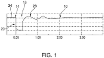
- FIG. 1 is an exemplary plot 10 of the voltage level over time across the AC terminals of a power source, such as a wind power unit, connected to a utility grid for an exemplary voltage disturbance caused by a fault.
- faults cause a generally square-shaped dip or sag 20 in the voltage level between the pre-fault voltage level 24 and the voltage level during recovery 28.
- EP1931009 discloses a method of synchronising a plurality of generators, connected in parallel to a supply network, in which a synchronisation signal based on a stored phase and frequency is transmitted to the generators during a fault condition on the network.
- US2010/001527 A1 discloses a method of correcting AC output of a power convertor, in which a phase angle correction is carried out to avoid a power surge after the fault is remedied.
- the present disclosure is directed to a method of controlling the AC output of a power converter connected to an AC power network subject to a voltage fault that causes a network voltage on the AC power network to drop below a normal operating level during a fault period.
- the method is characterised by estimating the phase angle of the voltage anticipated to be present on the AC power network when the network voltage recovers from the voltage fault; and controlling a current of the AC output during the voltage fault as a function of the phase angle estimated; wherein the network voltage has an amplitude and said estimating includes tracking the phase with a response time and changing the response time in inverse proportion to the amplitude of the network voltage.
- the present disclosure is directed to an apparatus for controlling the AC output of a power converter connected to an AC power network subject to a voltage fault, in accordance with claim 13.
- the present disclosure is directed to a machine-readable storage medium containing machine-executable instructions for performing the claimed method of controlling the AC output of a power converter connected to an AC power network subject to a voltage fault.
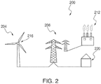
- FIG. 2 this figure illustrates an exemplary alternating current (AC) power system 200 that includes a wind power unit (WPU) 204 that delivers electrical energy to a power network 208, which is also supplied with power by one or more additional power sources, such as a coal fired power plant 212.
- a power converter 216 is coupled between WPU 204 and power network 208 for controlling electrical characteristics of the power delivered by the WPU to the network and that is ultimately delivered to end users, for example, utility customers, collectively represented in FIG. 2 by element 220.
- power converter 216 provides ride-through capabilities for WPU 204 during certain events that result in low voltage and/or zero voltage on power network 208.
- power converter 216 is designed and configured to allow WPU 204 to remain connected, and continue supplying power, to power network 208 during such events. In this manner, power converter 216 can provide support and stability for AC power system 200 by assisting in the stabilization of the voltage on power network 208 during smaller voltage drops and improving the recovery of the network after larger faults.
- aspects of the present invention may be applied to power generators such as, but not limited to, WPUs, solar power generators, fuels cells, micro-turbines, or flow batteries; energy storage systems such as, but not limited to, batteries, ultra-capacitors, superconducting energy storage, or flywheels; and loads, such as, but not limited to, electronic ballasted lighting systems, motor drives, etc.
- AC power system 200 can be, for example, a conventional utility grid or an isolated power network.
- Power converter 216 works for both single and multi-phase systems. In power networks containing groups of WPUs or other power generators, the energy output of a plurality of generators can have their power output controlled by a single inverter control system configured as described herein.
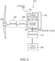
- FIG. 3 shows some of the mechanical and electrical components of a particular embodiment of WPU 204.
- WPU 204 includes a wind turbine 300 that rotates in response to the wind.
- Wind turbine 300 is coupled to a generator 304, which converts the rotational energy of the wind turbine into electrical energy in AC form.
- a rectifier 308 converts the AC power produced by generator 304 to direct current (DC), which is then further conditioned by power converter 216 from DC to AC power at a frequency and phase angle appropriate for transmission onto power network 208 ( FIG. 2 ).
- Power converter 216 is coupled to a transformer 312, which modifies the converter output 316 (i.e., voltage produced by WPU 204) to the voltage on utility grid 208.
- Power converter 216 includes converter circuitry 320 and a control system 324 and is capable of regulating currents provided to power network 208 by following a set of reference currents generated by the control system.
- Power converter 216 is typically a current regulated power inverter.
- Converter circuitry 320 is electronically coupled to and controlled by control system 324 (an example of which is shown in detail in FIG. 4 ) using a command signal 328, which is a control signal based on the phase of the voltage on power network 208 ( FIG. 2 ).
- Control system 324 is configured to essentially provide an estimate of the phase angle of the current at the time of recovery from a fault, for example time 16 in FIG. 1 .
- such estimate can be achieved by providing a phase tracking system that responds so slowly to voltage changes on power network 208 at all times of operation that it continues at about the same speed (frequency) during the fault, generally not being affected by the voltage disturbance.
- Such estimate can alternatively be provided by essentially freezing the value of command signal 328 to the value that exists when a voltage drop indicative of a ride-through event occurring on power network 208 ( FIG. 2 ) is experienced.
- PLL phase-locked loop
- control system 324 includes a controller 400 and a phase tracker 404.
- Controller 400 receives several input signals including, but not limited to, a network voltage signal 408 and a current signal 412 representative of the voltage and current at the output terminals of the WPU 204 or converter 216, respectively.
- Controller 400 also receives a real current command 416 and a reactive current command 420 from system level controls (not shown), as those skilled in the art will appreciate.
- Controller 400 further receives a controller phase reference signal 424 from phase tracker 404 that is used in an algorithm, along with the aforementioned signals and commands, to instruct converter circuitry 320 as to the proper phase and frequency of the current output sent to utility grid 208.
- controller 400 implements control code in a digital processor or other digital device; however, those of ordinary skill in the art would recognize that the controller can alternatively be implemented using analog circuitry.
- controller 400 may be the controller described in U.S. Patent No. 6,693,409 to Lynch et al. entitled “Control System For a Power Converter and Method of Controlling Operation of a Power Converter” or the controller described in U.S. Patent No. 7,492,617 to Petter et al. entitled “Frequency Control and Power Balancing in Disturbed Power Inverter System and Method Thereof".
- control system 324 is made to respond so slowly to changes in the frequency of the voltage on power network 208 at all times during operation that it is largely not affected by a voltage sag or drop.
- phase tracker 404 can be designed to be slow at all times of its operation, i.e., not only during low(zero)-voltage ride through events, but also while tracking the frequency of the voltage when the network voltage is at its normal level.
- "nominal frequency tracking time constant” is defined as the time constant of phase tracker 404 when the network voltage is nominal. It is noted that this time constant drops proportionally with grid voltage during a low voltage event.
- the present inventor has empirically found that a suitable definition of "slow" relative to the tracking of the frequency of the network voltage is that the response time of phase tracker, i.e., the nominal frequency tracking time constant, should be about 1/4 to about 2 times the maximum ride-through fault period.
- the maximum ride-through fault period is defined as the maximum time that the voltage is below 1/3 of nominal for which the system is to stay connected.
- the ride-through fault time over voltage curve is typically defined by one or more utilities or other entities responsible for setting the operating parameters and criteria for the power network at issue, here, power network 208.
- the maximum ride though fault period for FERC Order 661-A is about 1 second and in some codes as short as 0.3 seconds.
- fault disturbances with large voltage-phase shifts are short in duration, typically less than 100ms and virtually always less than 500ms.
- the present inventor has also empirically found that workable values of the nominal frequency tracking time constant for phase tracker 404 in this example range from about 25ms to about 2s. In one implementation, the response time is about 300mS.
- the nominal frequency tracking time constant should be from about 1 to about 5 times the length of the desired time that the system is to ride through a very low voltage event. For convenience, this time is referred to herein as the "very low voltage time,” or "VLVT,” for short.
- the VLVT is the time that the system needs to ride through at a level of less than about 15% to 20% of nominal voltage.
- FIG. 7 shows a graph 700 illustrating exemplary voltage ride-through requirements. Those skilled in the art may recognize that graph 700 is taken from the 2009 FERC draft standard PRC-024-1.
- Graph 700 is a graph of voltage per unit (PU), with the voltage taken at the point of interconnect (POI), versus time, and shows both a low-voltage-event curve 704 and a high-voltage-event curve 708.
- the region between curves 704 and 708 is the no trip zone, or ride-through region 712.
- the VLVT of this example is 0.15s, such that the nominal frequency tracking time constant according to the teaching of this example should be about 0.15s to about 0.75s, i.e., about 1 to about 5 times the VLVT, here 0.15s.
- phase tracker 404 will understand how to adjust the value of the nominal frequency tracking time constant of phase tracker 404 given the conditions and characteristics of the power network at issue, as well as the parameters of phase tracker.
- the choice of the time constant is a tradeoff between fast response which is need for fast power changes during normal operation and slower response for good LVRT performance.
- this scheme of implementing slow tracking times is contrary to typical conventional power converter control schemes that use fast tracking speeds and various state machines to deal with ride-through requirements.
- an augmentation to the disclosed slow-tracking scheme is to provide phase tracker 404 with the innate ability to slow its response time from an already slow value to a slower value in proportion to the voltage at the terminals of the wind turbine.
- a simple way of implementing this slowdown feature using a PLL is describe below in connection with FIG. 5 .
- phase tracker 404 can be provided with a ride-through-event detector 432 designed and configured, for example, to detect via network voltage signal 408 when the network voltage has dropped below a preset level.
- a ride-through-event detector 432 designed and configured, for example, to detect via network voltage signal 408 when the network voltage has dropped below a preset level.
- the present inventor has empirically determined that values of the preset level useful in the context of this feature include values that fall in the range of about 25% to about 50% of the normal operating voltage level on the power network at issue, here, power network 208. That said, others may find values of the preset level outside of the range provided to be useful.
- ride-through-event detector 432 is a voltage comparator that compares the voltage of network voltage signal 408 to a reference voltage set to the preset level just described. When the network voltage falls below the preset level, ride-through-event detector 432 triggers phase tracker 404 to freeze the frequency of controller phase reference signal 424 at its then-current value.
- phase tracker 404 including a PLL is described below in connection with FIG. 5 . That said, those skilled in the art should be able to devise alternative ways of achieving this freezing of frequency of controller phase reference signal 424.
- phase reference signal 424 when frozen during the fault event, will have substantially the same value as it does during periods of normal network voltage.
- controller phase reference signal 424 can be unfrozen when the voltage recovers back above the preset level.
- phase tracker 404 includes a PLL.
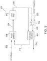
- FIG. 5 illustrates an exemplary PLL 500 suitable for use in phase tracker 404. Similar to controller 400, those skilled in the art that PLL 500 will typically be implemented in software, but can alternatively be implemented in hardware. As seen in FIG. 5 , PLL 500 includes three primary components: a controlled oscillator 504; a phase detector 508; and a loop filter 512. As those skilled in the art will understand, controlled oscillator 504 generates an AC reference signal 516 as a function of a phase error signal 520. Phase detector 508 outputs a detector signal 524 that is a function of the phase difference between AC voltage signal 332 and AC reference signal 516.
- phase detector 508 is a multiplier that multiplies AC reference signal 516 and AC voltage signal 332 with one another.
- This simple type of phase error detector has the characteristic of the phase error being proportional to the amplitude of the voltage as well as the phase error. This is what gives the PLL the innate characteristic of having its frequency and phase tracking response time a function of the voltage level Detector signal 524 is then operated on by loop filter 512 to remove unwanted features of detector signal 524.
- loop filter 512 is a low-pass filter designed and configured to rid detector signal 514 of the double-frequency term that results from the multiplication.
- the output of loop filter 512 is phase-error signal 520.
- PLL 500 can operate using an optional centering frequency signal 528 generated, for example, by operator-programmable hardware or software (not shown).
- centering frequency signal 528 gives PLL 500 a reference point and maintains the output of loop filter 512 near zero.
- frequency error signal 520 is combined with the center frequency signal in summation circuit 532, and the resultant signal 536 is output to controlled oscillator 504.
- Controlled oscillator 504 also outputs a phase reference signal 540 that is the phase of the AC reference signal 516 used in the feedback loop to phase detector 508.
- phase reference signal 540 corresponds to controller phase reference signal 424
- controller 400 uses the controller phase reference signal to generate current commands 428 ( FIG. 4 ), which include a real current waveform and a reactive current waveform, for converter circuitry 320 ( FIGS. 3 and 4 ).
- phase tracking system 404 ( FIG. 4 ) is designed and configured to track the phase of the voltage on power network 208 slowly so as to largely keep controller phase reference signal 424 unaffected by a fast voltage sag or dip due to a ride-through fault voltage disturbance.
- this slowness can be achieved by selecting the appropriate gain constants and other operating parameters of the PLL.
- Those skilled in the art will readily understand how to tune the response time of PLL 500 according to the guidance provided above on response times of phase tracker 404 ( FIG. 4 ) for a given PLL design.
- converter control system 216 FIGS. 2-4
- phase tracker 404 of FIG. 4 can be enhanced by designing and configuring it to slow its response as a function of the network voltage.
- this can be achieved by making phase detector 508 an amplitude-sensitive phase detector such that its phase error output is a function of both phase error and voltage level.
- the speed of PLL 500 would decrease with the decreased amplitude of the network voltage, represented by AC voltage 332, during the sag or drop thus slowing the response time to phase and frequency changes.
- Amplitude-sensitive phase detectors are known in the art, and, therefore, further details are not needed for those skilled in the art to implement PLL 500 with a suitable amplitude-sensitive phase detector for phase detector 508.
- phase tracker 404 ( FIG. 4 ) is designed and configured so that once it detects that the network voltage on network 208 drops below a certain level, it maintains the frequency of controller phase reference signal 424 ( FIG. 4 ) then current at substantially the time of the detection.
- phase tracker 404 is implemented as a PLL, such as PLL 500 of FIG. 5
- the freezing of phase reference signal 540 (which, again, corresponds to controller phase reference signal 424 of FIG. 4 in the context of phase tracker 404) can be achieved by setting the value of either phase error signal 520 or detector signal 524 ( FIG.
- phase error signal 520 or detector signal 524 to zero effectively holds the frequency of phase reference signal 540 at the frequency at the time of freezing. If the response time of PLL 500 is suitably slow as described above, the frequency of frozen phase reference signal 540 will be roughly the frequency that was present just prior to the occurrence of the fault that caused the sag or drop.
- phase error signal 520 or detector signal 424 can be achieved in a variety of ways.
- a multiplexer (not shown) that selects between a live value of phase error signal 520 and a constant-zero signal as a function of a selection signal, for example from ride-through-event detector 432 ( FIG. 4 ) could be added between loop filter 512 and controlled oscillator 504.
- a register that holds a value of phase error signal could be temporarily loaded with the value of zero during the freezing period.
- phase error signal 520 is set to zero in response to a voltage ride-through event, similar techniques can be used for returning phase error signal to live values when appropriate. Similar schemes could be applied to detector signal 424, as well.
- control system 324 ( FIG. 3 ) generates command signal 328 that instructs converter circuitry 320 to deliver a current waveform at a particular phase relative to the voltage existing on utility grid 208.
- Command signal 328 may be generated digitally using look-up tables, using analog circuitry, or it may be a software routine executing, for example, a trigonometric sine and cosine function.
- the strategy is to let the AC current command phase be controlled by the phase of phase reference signal 540.
- phase tracker 404 FIG.
- Control system 324 ( FIGS. 3 and 4 ) can be relatively simple or very complex, incorporating many functions of wind-turbine control.
- Control system 324 may be an independent circuit simply for the functions related to the technique of the present invention or may simply be a part of the converter or some other component of the wind turbine system or aspects of the converter control circuit spread out among components.
- Control system 324, as shown in FIG. 4 may be embodied as a physical hardware component or it can be implemented in software using, for example, a microprocessor.
- any one or more of the aspects and embodiments described herein may be conveniently implemented using one or more machines (e.g., one or more computing devices that are utilized as a user computing device for an electronic document, one or more server devices, such as a document server) programmed according to the teachings of the present specification, as will be apparent to those of ordinary skill in the computer art.
- Appropriate software coding can readily be prepared by skilled programmers based on the teachings of the present disclosure, as will be apparent to those of ordinary skill in the software art.
- Aspects and implementations discussed above employing software and/or software modules may also include appropriate hardware for assisting in the implementation of the machine executable instructions of the software and/or software module.
- Such software may be a computer program product that employs a machine-readable storage medium.
- a machine-readable storage medium may be any medium that is capable of storing and/or encoding a sequence of instructions for execution by a machine (e.g., a computing device) and that causes the machine to perform any one of the methodologies and/or embodiments described herein.
- Examples of a machine-readable storage medium include, but are not limited to, a magnetic disk (e.g., a conventional floppy disk, a hard drive disk), an optical disk (e.g., a compact disk “CD”, such as a readable, writeable, and/or re-writable CD; a digital video disk “DVD”, such as a readable, writeable, and/or rewritable DVD), a magneto-optical disk, a read-only memory "ROM” device, a random access memory “RAM” device, a magnetic card, an optical card, a solid-state memory device (e.g., a flash memory), an EPROM, an EEPROM, and any combinations thereof.
- a magnetic disk e.g., a conventional floppy disk, a hard drive disk
- an optical disk e.g., a compact disk "CD”, such as a readable, writeable, and/or re-writable CD; a digital video disk “DVD”,
- a machine-readable medium is intended to include a single medium as well as a collection of physically separate media, such as, for example, a collection of compact disks or one or more hard disk drives in combination with a computer memory.
- a machine-readable storage medium does not include a signal and information carried on a carrier wave.
- Such software may also include information (e.g., data) carried as a data signal on a data carrier, such as a carrier wave.
- a data carrier such as a carrier wave.
- machine-executable information may be included as a data-carrying signal embodied in a data carrier in which the signal encodes a sequence of instruction, or portion thereof, for execution by a machine (e.g., a computing device) and any related information (e.g., data structures and data) that causes the machine to perform any one of the methodologies and/or embodiments described herein.
- Examples of a computing device include, but are not limited to, an electronic book reading device, a computer workstation, a terminal computer, a server computer, a handheld device (e.g., a tablet computer, a personal digital assistant "PDA", a mobile telephone, a smartphone, etc.), a web appliance, a network router, a network switch, a network bridge, any machine capable of executing a sequence of instructions that specify an action to be taken by that machine, and any combinations thereof.
- a computing device may include and/or be included in a kiosk.
- FIG. 6 shows a diagrammatic representation of one embodiment of a computing device in the exemplary form of a computer system 600 within which a set of instructions for causing a control system, such as converter control system 324 of FIG. 3 , to perform any one or more of the aspects and/or methodologies of the present disclosure may be executed. It is also contemplated that multiple computing devices may be utilized to implement a specially configured set of instructions for causing the device to perform any one or more of the aspects and/or methodologies of the present disclosure.
- Computer system 600 includes a processor 604 and a memory 608 that communicate with each other, and with other components, via a bus 612.
- Bus 612 may include any of several types of bus structures including, but not limited to, a memory bus, a memory controller, a peripheral bus, a local bus, and any combinations thereof, using any of a variety of bus architectures.
- Memory 608 may include various components (e.g., machine readable media) including, but not limited to, a random access memory component (e.g, a static RAM “SRAM”, a dynamic RAM “DRAM”, etc.), a read only component, and any combinations thereof.
- a basic input/output system 616 (BIOS), including basic routines that help to transfer information between elements within computer system 600, such as during start-up, may be stored in memory 608.
- BIOS basic input/output system
- Memory 608 may also include (e.g., stored on one or more machine-readable media) instructions (e.g., software) 620 embodying any one or more of the aspects and/or methodologies of the present disclosure.
- memory 608 may further include any number of program modules including, but not limited to, an operating system, one or more application programs, other program modules, program data, and any combinations thereof.
- Computer system 600 may also include a storage device 624.
- a storage device e.g., storage device 624.
- Examples of a storage device include, but are not limited to, a hard disk drive for reading from and/or writing to a hard disk, a magnetic disk drive for reading from and/or writing to a removable magnetic disk, an optical disk drive for reading from and/or writing to an optical medium (e.g., a CD, a DVD, etc.), a solid-state memory device, and any combinations thereof.
- Storage device 624 may be connected to bus 612 by an appropriate interface (not shown).
- Example interfaces include, but are not limited to, SCSI, advanced technology attachment (ATA), serial ATA, universal serial bus (USB), IEEE 1394 (FIREWIRE), and any combinations thereof.
- storage device 624 (or one or more components thereof) may be removably interfaced with computer system 600 (e.g., via an external port connector (not shown)).
- storage device 624 and an associated machine-readable storage medium 628 may provide nonvolatile and/or volatile storage of machine-readable instructions, data structures, program modules, and/or other data for computer system 600.
- software 620 may reside, completely or partially, within machine-readable storage medium 628.
- software 620 may reside, completely or partially, within processor 604. It is noted that the term "machine-readable storage medium” does not include transitory signals, such as carrier-wave based signals and carrierless signals.
- Computer system 600 may also include an input device 632.
- a user of computer system 600 may enter commands and/or other information into computer system 600 via input device 632.
- Examples of an input device 632 include, but are not limited to, an alpha-numeric input device (e.g., a keyboard), a pointing device, a joystick, a gamepad, an audio input device (e.g., a microphone, a voice response system, etc.), a cursor control device (e.g., a mouse), a touchpad, an optical scanner, a video capture device (e.g., a still camera, a video camera), touchscreen, and any combinations thereof.
- an alpha-numeric input device e.g., a keyboard
- a pointing device e.g., a joystick, a gamepad
- an audio input device e.g., a microphone, a voice response system, etc.
- a cursor control device e.g., a mouse
- Input device 632 may be interfaced to bus 612 via any of a variety of interfaces (not shown) including, but not limited to, a serial interface, a parallel interface, a game port, a USB interface, a FIREWIRE interface, a direct interface to bus 612, and any combinations thereof.
- Input device 632 may include a touch screen interface that may be a part of or separate from display 636, discussed further below.
- Input device 632 may be utilized as a user selection device for selecting one or more graphical representations in a graphical interface as described above.
- a user may also input commands and/or other information to computer system 600 via storage device 624 (e.g., a removable disk drive, a flash drive, etc.) and/or network interface device 640.
- a network interface device such as network interface device 640 may be utilized for connecting computer system 600 to one or more of a variety of networks, such as network 644, and one or more remote devices 648 connected thereto. Examples of a network interface device include, but are not limited to, a network interface card (e.g., a mobile network interface card, a LAN card), a modem, and any combination thereof.
- Examples of a network include, but are not limited to, a wide area network (e.g., the Internet, an enterprise network), a local area network (e.g., a network associated with an office, a building, a campus or other relatively small geographic space), a telephone network, a data network associated with a telephone/voice provider (e.g., a mobile communications provider data and/or voice network), a direct connection between two computing devices, and any combinations thereof.
- a network such as network 644, may employ a wired and/or a wireless mode of communication. In general, any network topology may be used.
- Information e.g., data, software 620, etc.
- Computer system 600 may further include a video display adapter 652 for communicating a displayable image to a display device, such as display device 636.
- a display device include, but are not limited to, a liquid crystal display (LCD), a cathode ray tube (CRT), a plasma display, a light emitting diode (LED) display, and any combinations thereof.
- Display adapter 652 and display device 636 may be utilized in combination with processor 604 to provide a graphical representation of a utility resource, a location of a land parcel, and/or a location of an easement to a user.
- a computer system 600 may include one or more other peripheral output devices including, but not limited to, an audio speaker, a printer, and any combinations thereof.
- peripheral output devices may be connected to bus 612 via a peripheral interface 656. Examples of a peripheral interface include, but are not limited to, a serial port, a USB connection, a FIREWIRE connection, a parallel connection, and any combinations thereof.
Landscapes
- Engineering & Computer Science (AREA)
- Power Engineering (AREA)
- Life Sciences & Earth Sciences (AREA)
- Sustainable Development (AREA)
- Sustainable Energy (AREA)
- Chemical & Material Sciences (AREA)
- Combustion & Propulsion (AREA)
- Mechanical Engineering (AREA)
- General Engineering & Computer Science (AREA)
- Inverter Devices (AREA)
- Supply And Distribution Of Alternating Current (AREA)
- Ac-Ac Conversion (AREA)
Claims (15)
- Verfahren zur Steuerung des Wechselstromausgangs eines Stromwandlers (216), der mit einem Wechselstromnetz (208) verbunden ist, das einer Spannungsstörung unterliegt, die eine Netzwerkspannung auf dem Wechselstromnetz unter ein Normal-Betriebsniveau während einer Störungsperiode fallen lässt, gekennzeichnet durch:Abschätzen des Phasenwinkels der Spannung, die voraussichtlich auf dem Wechselstromnetz vorhanden ist, wenn sich die Netzspannung von der Spannungsstörung erholt; undSteuern eines Stromes der Wechselstromausgabe während der Spannungsstörung als eine Funktion des geschätzten Phasenwinkels;wobei die Netzspannung eine Amplitude aufweist und wobei das Abschätzen ein Nachführen der Phase mit einer Ansprechzeit und ein Ändern der Ansprechzeit umgekehrt proportional zur Amplitude der Netzspannung umfasst.
- Verfahren nach Anspruch 1, wobei erforderlich ist, dass der Stromwandler (216) mit dem Wechselstromnetz (208) während einer maximalen Durchlauf-Störungsperiode mit sehr geringem zeitlichen Spannungsverlauf verbunden bleibt, und wobei das Abschätzen ein Nachführen einer Phase der Netzspannung mit einer Zeitkonstanten gleich etwa dem 1-fachen des sehr geringen zeitlichen Spannungsverlaufs bis etwa dem 5-fachen des sehr geringen zeitlichen Spannungsverlaufs umfasst.
- Verfahren nach Anspruch 1, wobei erforderlich ist, dass der Stromwandler (216) mit dem Wechselstromnetz (208) während einer maximalen Durchlauf-Störungsperiode mit sehr geringem zeitlichen Spannungsverlauf verbunden bleibt, und wobei das Abschätzen ein Nachführen einer Phase der Netzspannung mit einer Ansprechzeit von etwa ¼ bis etwa dem 2-fachen der maximalen Durchlauf-Störungsperiode umfasst.
- Verfahren nach einem der Ansprüche 1 bis 3, wobei der Phasenwinkel unter Verwendung eines Phasenregelkreises (500) abgeschätzt wird.
- Verfahren nach einem der Ansprüche 1 bis 4, wobei das Ändern der Ansprechzeit unter Verwendung eines Phasenregelkreises (500) mit einem Amplitudensensitiven Phasendetektor (500) umfasst.
- Verfahren nach Anspruch 4 oder 5, wobei das Abschätzen unter Verwendung eines Abschätzverfahrens durchgeführt wird, das Betriebsparameter verwendet, welche die gleichen sind wie vor, während und nach der Störungsperiode.
- Verfahren nach einem der Ansprüche 1 bis 6, wobei die Ansprechzeit wenigstens 25 Millisekunden beträgt.
- Verfahren nach Anspruch 7, wobei die Ansprechzeit wenigstens 100 Millisekunden beträgt.
- Verfahren nach Anspruch 8, wobei die Ansprechzeit wenigstens 1 Sekunde beträgt.
- Verfahren nach Anspruch 4, wobei die Frequenz-Nachführ-Zeitkonstante gleich etwa dem 1-fachen des sehr geringen zeitlichen Spannungsverlaufs bis etwa dem 5-fachen des sehr geringen zeitlichen Spannungsverlaufs ist.
- Verfahren nach Anspruch 4, wobei das Abschätzen ein Nachführen einer Phase der Netzspannung mit einer Ansprechzeit von etwa ¼ bis etwa dem 2-fachen der maximalen Durchlauf-Störungsperiode umfasst.
- Verfahren nach Anspruch 1, wobei das Abschätzen ein Nachführen einer Phase der Spannung mit einem Phasenregelkreis umfasst, welcher Betriebsparameter aufweist, welche die gleichen sind sowohl in der Störungsperiode als auch während des Nachführens, wenn sich die Netzspannung auf dem Normal-Betriebsniveau befindet.
- Vorrichtung zum Steuern des Wechselstromausgangs eines Stromwandlers, der mit einem Wechselstromnetz verbunden ist, das einer Spannungsstörung unterliegt, die eine Netzwerkspannung auf dem Wechselstromnetz unter ein Normal-Betriebsniveau während einer Störungsperiode fallen lässt, wobei die Vorrichtung gekennzeichnet ist, indem sie umfasst:ein Steuersystem, welches dazu ausgebildet ist:den Phasenwinkel der Spannung abzuschätzen, der voraussichtlich auf dem Wechselstromnetz vorhanden ist, wenn sich die Netzspannung von der Spannungsstörung erholt; undeinen Strom der Wechselstromausgabe während der Spannungsstörung als eine Funktion des geschätzten Phasenwinkels zu steuern, wobei die Netzspannung eine Amplitude aufweist und wobei das Abschätzen ein Nachführen der Phase mit einer Ansprechzeit und ein Ändern der Ansprechzeit umgekehrt proportional zur Amplitude der Netzspannung umfasst.
- Vorrichtung nach Anspruch 13, wobei die Vorrichtung weiterhin dazu ausgebildet ist, das Verfahren nach einem der Ansprüche 2 bis 11 auszuführen.
- Maschinenlesbares Speichermedium, welches maschinenausführbare Anweisungen enthält, um ein Verfahren zum Steuern des Wechselstromausgangs eines Stromwandlers nach einem der Ansprüche 1 bis 12 durchzuführen.
Applications Claiming Priority (4)
| Application Number | Priority Date | Filing Date | Title |
|---|---|---|---|
| US42245110P | 2010-12-13 | 2010-12-13 | |
| US201061425510P | 2010-12-21 | 2010-12-21 | |
| US13/275,362 US20120147637A1 (en) | 2010-12-13 | 2011-10-18 | Methods, Systems, and Software for Controlling a Power Converter During Low (Zero)-Voltage Ride-Through Conditions |
| PCT/US2011/063252 WO2012082430A2 (en) | 2010-12-13 | 2011-12-05 | Methods, systems, and software for controlling a power converter during low (zero)-voltage ride-through conditions |
Publications (2)
| Publication Number | Publication Date |
|---|---|
| EP2652858A2 EP2652858A2 (de) | 2013-10-23 |
| EP2652858B1 true EP2652858B1 (de) | 2017-10-11 |
Family
ID=46199242
Family Applications (1)
| Application Number | Title | Priority Date | Filing Date |
|---|---|---|---|
| EP11799223.0A Active EP2652858B1 (de) | 2010-12-13 | 2011-12-05 | VERFAHREN, UND GERäT ZUR STEUERUNG EINES STROMWANDLERS WÄHREND EINES NIEDRIG- (NULL-) SPANNUNGS-FEHLERDURCHLAUFS |
Country Status (6)
| Country | Link |
|---|---|
| US (3) | US20120147637A1 (de) |
| EP (1) | EP2652858B1 (de) |
| CN (1) | CN103314498B (de) |
| BR (1) | BR112013014419B1 (de) |
| CA (1) | CA2818939C (de) |
| WO (1) | WO2012082430A2 (de) |
Families Citing this family (30)
| Publication number | Priority date | Publication date | Assignee | Title |
|---|---|---|---|---|
| JP3918837B2 (ja) * | 2004-08-06 | 2007-05-23 | 株式会社日立製作所 | 風力発電装置 |
| US20120147637A1 (en) * | 2010-12-13 | 2012-06-14 | Northern Power Systems, Inc. | Methods, Systems, and Software for Controlling a Power Converter During Low (Zero)-Voltage Ride-Through Conditions |
| KR101260611B1 (ko) * | 2011-07-20 | 2013-05-03 | 엘에스산전 주식회사 | 고압 인버터의 제어장치 및 방법 |
| CN102966336B (zh) * | 2012-01-10 | 2015-11-04 | 邱永安 | 风力直驱抽油机 |
| US20130270823A1 (en) * | 2012-04-17 | 2013-10-17 | Clipper Windpower, Llc | Method for Enhancing Low Voltage Ride Through Capability on a Wind Turbine |
| GB2503262B (en) * | 2012-06-20 | 2020-04-01 | Nidec Control Techniques Ltd | System and method for managing recovery of control in an electrical system |
| US9312699B2 (en) | 2012-10-11 | 2016-04-12 | Flexgen Power Systems, Inc. | Island grid power supply apparatus and methods using energy storage for transient stabilization |
| US10289080B2 (en) | 2012-10-11 | 2019-05-14 | Flexgen Power Systems, Inc. | Multi-generator applications using variable speed and solid state generators for efficiency and frequency stabilization |
| US9244506B2 (en) * | 2012-11-16 | 2016-01-26 | Siemens Aktiengesellschaft | Method of controlling a power plant |
| US9553517B2 (en) | 2013-03-01 | 2017-01-24 | Fllexgen Power Systems, Inc. | Hybrid energy storage system and methods |
| US9593672B2 (en) * | 2013-08-07 | 2017-03-14 | Siemens Aktiengesellschaft | Isochronous wind turbine generator capable of stand-alone operation |
| CN103501015B (zh) * | 2013-09-03 | 2015-09-30 | 国家电网公司 | 一种平抑光伏波动的储能系统控制方法 |
| US10544780B2 (en) * | 2013-10-21 | 2020-01-28 | Vestas Wind Systems A/S | Method for controlling a wind power plant and a wind power plant |
| CN103683333A (zh) * | 2013-12-31 | 2014-03-26 | 一重集团大连设计研究院有限公司 | 一种低电压穿越下变流器的控制系统和控制方法 |
| CN103825300B (zh) * | 2014-03-12 | 2015-09-30 | 浙江埃菲生能源科技有限公司 | 一种用于光伏并网逆变器零电压穿越的电网电压锁相方法 |
| US9157415B1 (en) | 2014-03-21 | 2015-10-13 | General Electric Company | System and method of controlling an electronic component of a wind turbine using contingency communications |
| CN103972904A (zh) * | 2014-04-28 | 2014-08-06 | 上海电力学院 | 一种光伏发电系统对称跌落低电压穿越无功控制方法 |
| TWI522767B (zh) * | 2014-06-17 | 2016-02-21 | 國立中央大學 | 太陽光能發電系統 |
| CN104158394A (zh) * | 2014-07-08 | 2014-11-19 | 安徽金峰新能源股份有限公司 | 光伏逆变器的自启动控制方法 |
| CN107534294B (zh) | 2014-12-30 | 2021-07-30 | 弗莱斯金电力系统公司 | 具有有功和无功功率控制的暂态功率稳定化设备 |
| CN106654330B (zh) * | 2015-11-03 | 2019-03-12 | 大连融科储能技术发展有限公司 | 液流电池交流侧输入输出特性估算方法及其系统 |
| US10024305B2 (en) * | 2015-11-10 | 2018-07-17 | General Electric Company | System and method for stabilizing a wind farm during one or more contingency events |
| CN109962491B (zh) * | 2017-12-22 | 2021-10-15 | 北京金风科创风电设备有限公司 | 风力发电机组的变流器的故障处理方法和故障处理装置 |
| EP3579370A1 (de) * | 2018-06-05 | 2019-12-11 | Nordex Energy GmbH | Verfahren zum betrieb einer windenergieanlage |
| CN110334935B (zh) * | 2019-06-27 | 2021-11-19 | 南方电网科学研究院有限责任公司 | 一种评估并网变换器暂态稳定性的方法、装置及存储介质 |
| CN111245029B (zh) * | 2020-01-15 | 2021-05-11 | 同济大学 | 一种微电源故障控制与微电网保护的协同处理方法 |
| CN112103992A (zh) * | 2020-08-24 | 2020-12-18 | 中国电力科学研究院有限公司 | 一种两级式光伏并网发电优化装置、控制系统及方法 |
| US11698053B2 (en) * | 2020-12-02 | 2023-07-11 | General Electric Renovables Espana, S.L. | System and method for controlling a wind turbine |
| CN113489025B (zh) * | 2021-07-15 | 2023-03-07 | 西安热工研究院有限公司 | 一种用于辅助火电机组agc调频超级电容装置的控制方法 |
| CN113746140B (zh) * | 2021-11-08 | 2022-02-11 | 四川大学 | 一种高压直流输电连续扰动下的双馈风机故障穿越方法 |
Family Cites Families (31)
| Publication number | Priority date | Publication date | Assignee | Title |
|---|---|---|---|---|
| US5239251A (en) | 1989-06-30 | 1993-08-24 | The State Of Oregon Acting By And Through The State Board Of Higher Education On Behalf Of Oregon State University | Brushless doubly-fed motor control system |
| US6784565B2 (en) | 1997-09-08 | 2004-08-31 | Capstone Turbine Corporation | Turbogenerator with electrical brake |
| JP4034458B2 (ja) * | 1999-01-20 | 2008-01-16 | 中部電力株式会社 | 自励式交直変換器制御装置および遮断器回路制御装置 |
| US6600973B1 (en) * | 1999-11-24 | 2003-07-29 | American Supercondutor Corporation | Method and apparatus for providing power to a utility network |
| US6285533B1 (en) | 1999-12-13 | 2001-09-04 | Kabushiki Kaisha Toshiba | Method of and apparatus for controlling the operation of variable speed gearing |
| US6362988B1 (en) * | 2000-06-29 | 2002-03-26 | Ford Global Tech., Inc. | System and method for synchronizing the phase angle for an AC power source in parallel operation with a grid |
| DE10119624A1 (de) | 2001-04-20 | 2002-11-21 | Aloys Wobben | Verfahren zum Betreiben einer Windenergieanlage |
| EP2267859A3 (de) | 2001-07-23 | 2014-08-13 | Northern Power Systems Utility Scale, Inc. | Steuersystem für einen Leistungswandler und Verfahren zur Steuerung des Betriebs eines Leistungswandlers |
| US6531926B1 (en) | 2001-09-13 | 2003-03-11 | Overture Networks, Inc. | Dynamic control of phase-locked loop |
| DK174755B1 (da) | 2002-01-14 | 2003-10-20 | Vestas Wind Sys As | System til at forbinde en vindmøllegenerator med det elektriske forsyningsnet |
| US6919650B2 (en) * | 2002-05-31 | 2005-07-19 | Ballard Power Systems Corporation | Hybrid synchronization phase angle generation method |
| DE10232423A1 (de) | 2002-07-17 | 2004-01-29 | Ge Wind Energy Gmbh | Verfahren zum Betreiben einer Windenergieanlage und Windenergieanlage zum Ausführen derartiger Verfahren |
| US6921985B2 (en) | 2003-01-24 | 2005-07-26 | General Electric Company | Low voltage ride through for wind turbine generators |
| CA2515436C (en) | 2003-02-07 | 2012-04-10 | Vestas Wind Systems A/S | Method for controlling a power-grid connected wind turbine generator during grid faults and apparatus for implementing said method |
| US7233129B2 (en) | 2003-05-07 | 2007-06-19 | Clipper Windpower Technology, Inc. | Generator with utility fault ride-through capability |
| DK1665495T3 (da) | 2003-09-23 | 2012-03-26 | Aloys Wobben | Fremgangsmåde til drift af et vindenergianlæg under en forstyrrelse i nettet |
| EP1831987B2 (de) | 2004-12-28 | 2020-02-05 | Vestas Wind Systems A/S | Verfahren zur regelung einer mit dem netz verbundenen windkraftanlage |
| US7492617B2 (en) | 2005-06-29 | 2009-02-17 | Northern Power Systems, Inc. | Frequency control and power balancing in disturbed power inverter system and method thereof |
| US7253537B2 (en) | 2005-12-08 | 2007-08-07 | General Electric Company | System and method of operating double fed induction generators |
| US7456695B2 (en) * | 2006-01-10 | 2008-11-25 | General Electric Company | Apparatus, method and computer program product for tracking information in an electric grid |
| US7607896B2 (en) | 2006-04-28 | 2009-10-27 | Baker Hughes Incorporated | Systems and methods for power ride-through in variable speed drives |
| US7629705B2 (en) | 2006-10-20 | 2009-12-08 | General Electric Company | Method and apparatus for operating electrical machines |
| DE102006050077A1 (de) * | 2006-10-24 | 2008-05-08 | Repower Systems Ag | Umrichter mit steuerbarem Phasenwinkel |
| WO2008055499A2 (en) * | 2006-11-06 | 2008-05-15 | Gamesa Innovation & Technology, S.L. | Advanced real-time grid monitoring system and method |
| GB2444528B (en) * | 2006-12-09 | 2011-07-06 | Converteam Ltd | Methods for synchronising a plurality of generators |
| EP2122821A1 (de) * | 2007-02-26 | 2009-11-25 | Newcastle Innovation Limited | Integrierter windturbinenregler und umrichter |
| DE102007049251A1 (de) * | 2007-10-12 | 2009-04-23 | Repower Systems Ag | Windenergieanlagen mit Regelung für Netzfehler und Betriebsverfahren hierfür |
| DE102009031017B4 (de) * | 2009-06-29 | 2018-06-21 | Wobben Properties Gmbh | Verfahren und Vorrichtung zur Beobachtung eines dreiphasigen Wechselspannungsnetzes sowie Windenergieanlage |
| US8014181B2 (en) * | 2009-09-29 | 2011-09-06 | General Electric Company | Power conversion control system |
| CN201570870U (zh) * | 2009-11-18 | 2010-09-01 | 华锐风电科技(集团)股份有限公司 | 低电压穿越控制装置和风力发电设备 |
| US20120147637A1 (en) * | 2010-12-13 | 2012-06-14 | Northern Power Systems, Inc. | Methods, Systems, and Software for Controlling a Power Converter During Low (Zero)-Voltage Ride-Through Conditions |
-
2011
- 2011-10-18 US US13/275,362 patent/US20120147637A1/en not_active Abandoned
- 2011-12-05 WO PCT/US2011/063252 patent/WO2012082430A2/en not_active Ceased
- 2011-12-05 EP EP11799223.0A patent/EP2652858B1/de active Active
- 2011-12-05 BR BR112013014419-0A patent/BR112013014419B1/pt active IP Right Grant
- 2011-12-05 CA CA2818939A patent/CA2818939C/en active Active
- 2011-12-05 CN CN201180058940.0A patent/CN103314498B/zh not_active Expired - Fee Related
-
2012
- 2012-05-10 US US13/468,524 patent/US8467205B2/en active Active
-
2013
- 2013-05-29 US US13/904,458 patent/US8792259B2/en active Active
Non-Patent Citations (1)
| Title |
|---|
| None * |
Also Published As
| Publication number | Publication date |
|---|---|
| US8467205B2 (en) | 2013-06-18 |
| WO2012082430A3 (en) | 2012-09-07 |
| CA2818939A1 (en) | 2012-06-21 |
| US20120218791A1 (en) | 2012-08-30 |
| CN103314498A (zh) | 2013-09-18 |
| BR112013014419B1 (pt) | 2020-10-27 |
| EP2652858A2 (de) | 2013-10-23 |
| WO2012082430A2 (en) | 2012-06-21 |
| CN103314498B (zh) | 2015-11-25 |
| BR112013014419A2 (pt) | 2016-09-13 |
| US8792259B2 (en) | 2014-07-29 |
| US20120147637A1 (en) | 2012-06-14 |
| US20130286696A1 (en) | 2013-10-31 |
| CA2818939C (en) | 2019-01-08 |
Similar Documents
| Publication | Publication Date | Title |
|---|---|---|
| EP2652858B1 (de) | VERFAHREN, UND GERäT ZUR STEUERUNG EINES STROMWANDLERS WÄHREND EINES NIEDRIG- (NULL-) SPANNUNGS-FEHLERDURCHLAUFS | |
| US7804184B2 (en) | System and method for control of a grid connected power generating system | |
| CN101929439B (zh) | 风电场中的电流控制 | |
| Yuan et al. | Control of variable pitch and variable speed direct‐drive wind turbines in weak grid systems with active power balance | |
| EP3472908A1 (de) | Energieverwaltungssystem und verfahren zur erzeugung von netzgekoppelter und inselmikroenergie | |
| CN104620460B (zh) | 低电压或高电压事件期间的发电设备控制 | |
| US20100148508A1 (en) | Control method and apparatus | |
| US10236817B2 (en) | Integrated control architecture and method for a bi-directional AC-to-AC converter | |
| CN103580068A (zh) | 用于控制功率转换器的系统和方法 | |
| JP4846450B2 (ja) | インバータ電源制御装置 | |
| US10224831B1 (en) | Control systems, methods, and software for keeping power converters within operating limits during disturbances | |
| Yuan et al. | Control strategies for permanent magnet synchronous generator‐based wind turbine with independent grid‐forming capability in stand‐alone operation mode | |
| Miranbeigi et al. | Collaborative volt-var control using grid-connected PV inverters | |
| Das et al. | Improved RLS algorithm for voltage regulation of wind-solar rural renewable energy system | |
| Fradley et al. | Fast frequency response from MMC-HVDC with varying dead band implementation | |
| Shukla et al. | Control of an Offshore Bipole with AC Interlink Under Dedicated Metallic Return Fault to Improve Energy Availability | |
| CN110061518A (zh) | 用于操作风力涡轮机的方法 | |
| Mohamed et al. | Improved Control Approaches for Dynamic Voltage Restoration in Doubly Fed Induction Generator-Based Wind Turbines | |
| SHABAN et al. | Improved Control Approaches for Dynamic Voltage Restoration in Doubly Fed Induction Generator-Based Wind Turbines | |
| Akinloye et al. | Grid-Forming Inverter through Current-Limiting Strategy for Power Synchronization Control | |
| Fan et al. | Enabling Technology for Energy Sustainability: Power Electronic Converter Control for Renewables | |
| Tsotsopoulou et al. | Transient stability enhancement of multi-infeed AC offshore islands for large-scale HVDC interconnection and wind integration | |
| Liu et al. | Disturbance rejection strategies for AC/DC microgrids | |
| Ramsumar | The control of power electronic converters for grid code compliance in wind energy generation systems | |
| Kumar et al. | energies MDPI |
Legal Events
| Date | Code | Title | Description |
|---|---|---|---|
| PUAI | Public reference made under article 153(3) epc to a published international application that has entered the european phase |
Free format text: ORIGINAL CODE: 0009012 |
|
| 17P | Request for examination filed |
Effective date: 20130712 |
|
| AK | Designated contracting states |
Kind code of ref document: A2 Designated state(s): AL AT BE BG CH CY CZ DE DK EE ES FI FR GB GR HR HU IE IS IT LI LT LU LV MC MK MT NL NO PL PT RO RS SE SI SK SM TR |
|
| DAX | Request for extension of the european patent (deleted) | ||
| RAP1 | Party data changed (applicant data changed or rights of an application transferred) |
Owner name: NORTHERN POWER SYSTEMS, INC. |
|
| GRAP | Despatch of communication of intention to grant a patent |
Free format text: ORIGINAL CODE: EPIDOSNIGR1 |
|
| STAA | Information on the status of an ep patent application or granted ep patent |
Free format text: STATUS: GRANT OF PATENT IS INTENDED |
|
| RIC1 | Information provided on ipc code assigned before grant |
Ipc: F03D 9/25 20160101ALI20170331BHEP Ipc: H02J 3/24 20060101ALI20170331BHEP Ipc: H02P 9/10 20060101ALI20170331BHEP Ipc: H02J 3/40 20060101AFI20170331BHEP |
|
| INTG | Intention to grant announced |
Effective date: 20170421 |
|
| GRAS | Grant fee paid |
Free format text: ORIGINAL CODE: EPIDOSNIGR3 |
|
| GRAA | (expected) grant |
Free format text: ORIGINAL CODE: 0009210 |
|
| STAA | Information on the status of an ep patent application or granted ep patent |
Free format text: STATUS: THE PATENT HAS BEEN GRANTED |
|
| AK | Designated contracting states |
Kind code of ref document: B1 Designated state(s): AL AT BE BG CH CY CZ DE DK EE ES FI FR GB GR HR HU IE IS IT LI LT LU LV MC MK MT NL NO PL PT RO RS SE SI SK SM TR |
|
| RAP1 | Party data changed (applicant data changed or rights of an application transferred) |
Owner name: WEG ELECTRIC CORP. |
|
| REG | Reference to a national code |
Ref country code: GB Ref legal event code: FG4D |
|
| REG | Reference to a national code |
Ref country code: CH Ref legal event code: EP |
|
| REG | Reference to a national code |
Ref country code: IE Ref legal event code: FG4D |
|
| REG | Reference to a national code |
Ref country code: AT Ref legal event code: REF Ref document number: 936819 Country of ref document: AT Kind code of ref document: T Effective date: 20171115 |
|
| REG | Reference to a national code |
Ref country code: DE Ref legal event code: R096 Ref document number: 602011042362 Country of ref document: DE |
|
| REG | Reference to a national code |
Ref country code: FR Ref legal event code: PLFP Year of fee payment: 7 |
|
| REG | Reference to a national code |
Ref country code: NL Ref legal event code: MP Effective date: 20171011 |
|
| REG | Reference to a national code |
Ref country code: LT Ref legal event code: MG4D |
|
| REG | Reference to a national code |
Ref country code: AT Ref legal event code: MK05 Ref document number: 936819 Country of ref document: AT Kind code of ref document: T Effective date: 20171011 |
|
| PG25 | Lapsed in a contracting state [announced via postgrant information from national office to epo] |
Ref country code: NL Free format text: LAPSE BECAUSE OF FAILURE TO SUBMIT A TRANSLATION OF THE DESCRIPTION OR TO PAY THE FEE WITHIN THE PRESCRIBED TIME-LIMIT Effective date: 20171011 |
|
| PG25 | Lapsed in a contracting state [announced via postgrant information from national office to epo] |
Ref country code: LT Free format text: LAPSE BECAUSE OF FAILURE TO SUBMIT A TRANSLATION OF THE DESCRIPTION OR TO PAY THE FEE WITHIN THE PRESCRIBED TIME-LIMIT Effective date: 20171011 Ref country code: FI Free format text: LAPSE BECAUSE OF FAILURE TO SUBMIT A TRANSLATION OF THE DESCRIPTION OR TO PAY THE FEE WITHIN THE PRESCRIBED TIME-LIMIT Effective date: 20171011 Ref country code: NO Free format text: LAPSE BECAUSE OF FAILURE TO SUBMIT A TRANSLATION OF THE DESCRIPTION OR TO PAY THE FEE WITHIN THE PRESCRIBED TIME-LIMIT Effective date: 20180111 Ref country code: SE Free format text: LAPSE BECAUSE OF FAILURE TO SUBMIT A TRANSLATION OF THE DESCRIPTION OR TO PAY THE FEE WITHIN THE PRESCRIBED TIME-LIMIT Effective date: 20171011 Ref country code: ES Free format text: LAPSE BECAUSE OF FAILURE TO SUBMIT A TRANSLATION OF THE DESCRIPTION OR TO PAY THE FEE WITHIN THE PRESCRIBED TIME-LIMIT Effective date: 20171011 |
|
| PG25 | Lapsed in a contracting state [announced via postgrant information from national office to epo] |
Ref country code: AT Free format text: LAPSE BECAUSE OF FAILURE TO SUBMIT A TRANSLATION OF THE DESCRIPTION OR TO PAY THE FEE WITHIN THE PRESCRIBED TIME-LIMIT Effective date: 20171011 Ref country code: GR Free format text: LAPSE BECAUSE OF FAILURE TO SUBMIT A TRANSLATION OF THE DESCRIPTION OR TO PAY THE FEE WITHIN THE PRESCRIBED TIME-LIMIT Effective date: 20180112 Ref country code: LV Free format text: LAPSE BECAUSE OF FAILURE TO SUBMIT A TRANSLATION OF THE DESCRIPTION OR TO PAY THE FEE WITHIN THE PRESCRIBED TIME-LIMIT Effective date: 20171011 Ref country code: HR Free format text: LAPSE BECAUSE OF FAILURE TO SUBMIT A TRANSLATION OF THE DESCRIPTION OR TO PAY THE FEE WITHIN THE PRESCRIBED TIME-LIMIT Effective date: 20171011 Ref country code: IS Free format text: LAPSE BECAUSE OF FAILURE TO SUBMIT A TRANSLATION OF THE DESCRIPTION OR TO PAY THE FEE WITHIN THE PRESCRIBED TIME-LIMIT Effective date: 20180211 Ref country code: BG Free format text: LAPSE BECAUSE OF FAILURE TO SUBMIT A TRANSLATION OF THE DESCRIPTION OR TO PAY THE FEE WITHIN THE PRESCRIBED TIME-LIMIT Effective date: 20180111 Ref country code: RS Free format text: LAPSE BECAUSE OF FAILURE TO SUBMIT A TRANSLATION OF THE DESCRIPTION OR TO PAY THE FEE WITHIN THE PRESCRIBED TIME-LIMIT Effective date: 20171011 |
|
| REG | Reference to a national code |
Ref country code: DE Ref legal event code: R097 Ref document number: 602011042362 Country of ref document: DE |
|
| PG25 | Lapsed in a contracting state [announced via postgrant information from national office to epo] |
Ref country code: EE Free format text: LAPSE BECAUSE OF FAILURE TO SUBMIT A TRANSLATION OF THE DESCRIPTION OR TO PAY THE FEE WITHIN THE PRESCRIBED TIME-LIMIT Effective date: 20171011 Ref country code: CZ Free format text: LAPSE BECAUSE OF FAILURE TO SUBMIT A TRANSLATION OF THE DESCRIPTION OR TO PAY THE FEE WITHIN THE PRESCRIBED TIME-LIMIT Effective date: 20171011 Ref country code: SK Free format text: LAPSE BECAUSE OF FAILURE TO SUBMIT A TRANSLATION OF THE DESCRIPTION OR TO PAY THE FEE WITHIN THE PRESCRIBED TIME-LIMIT Effective date: 20171011 Ref country code: DK Free format text: LAPSE BECAUSE OF FAILURE TO SUBMIT A TRANSLATION OF THE DESCRIPTION OR TO PAY THE FEE WITHIN THE PRESCRIBED TIME-LIMIT Effective date: 20171011 |
|
| REG | Reference to a national code |
Ref country code: CH Ref legal event code: PL |
|
| PLBE | No opposition filed within time limit |
Free format text: ORIGINAL CODE: 0009261 |
|
| STAA | Information on the status of an ep patent application or granted ep patent |
Free format text: STATUS: NO OPPOSITION FILED WITHIN TIME LIMIT |
|
| PG25 | Lapsed in a contracting state [announced via postgrant information from national office to epo] |
Ref country code: PL Free format text: LAPSE BECAUSE OF FAILURE TO SUBMIT A TRANSLATION OF THE DESCRIPTION OR TO PAY THE FEE WITHIN THE PRESCRIBED TIME-LIMIT Effective date: 20171011 Ref country code: RO Free format text: LAPSE BECAUSE OF FAILURE TO SUBMIT A TRANSLATION OF THE DESCRIPTION OR TO PAY THE FEE WITHIN THE PRESCRIBED TIME-LIMIT Effective date: 20171011 Ref country code: SM Free format text: LAPSE BECAUSE OF FAILURE TO SUBMIT A TRANSLATION OF THE DESCRIPTION OR TO PAY THE FEE WITHIN THE PRESCRIBED TIME-LIMIT Effective date: 20171011 |
|
| 26N | No opposition filed |
Effective date: 20180712 |
|
| REG | Reference to a national code |
Ref country code: IE Ref legal event code: MM4A |
|
| PG25 | Lapsed in a contracting state [announced via postgrant information from national office to epo] |
Ref country code: LU Free format text: LAPSE BECAUSE OF NON-PAYMENT OF DUE FEES Effective date: 20171205 Ref country code: MT Free format text: LAPSE BECAUSE OF NON-PAYMENT OF DUE FEES Effective date: 20171205 |
|
| REG | Reference to a national code |
Ref country code: BE Ref legal event code: MM Effective date: 20171231 |
|
| PG25 | Lapsed in a contracting state [announced via postgrant information from national office to epo] |
Ref country code: IE Free format text: LAPSE BECAUSE OF NON-PAYMENT OF DUE FEES Effective date: 20171205 |
|
| PG25 | Lapsed in a contracting state [announced via postgrant information from national office to epo] |
Ref country code: BE Free format text: LAPSE BECAUSE OF NON-PAYMENT OF DUE FEES Effective date: 20171231 Ref country code: SI Free format text: LAPSE BECAUSE OF FAILURE TO SUBMIT A TRANSLATION OF THE DESCRIPTION OR TO PAY THE FEE WITHIN THE PRESCRIBED TIME-LIMIT Effective date: 20171011 Ref country code: LI Free format text: LAPSE BECAUSE OF NON-PAYMENT OF DUE FEES Effective date: 20171231 Ref country code: CH Free format text: LAPSE BECAUSE OF NON-PAYMENT OF DUE FEES Effective date: 20171231 |
|
| PG25 | Lapsed in a contracting state [announced via postgrant information from national office to epo] |
Ref country code: MC Free format text: LAPSE BECAUSE OF FAILURE TO SUBMIT A TRANSLATION OF THE DESCRIPTION OR TO PAY THE FEE WITHIN THE PRESCRIBED TIME-LIMIT Effective date: 20171011 Ref country code: HU Free format text: LAPSE BECAUSE OF FAILURE TO SUBMIT A TRANSLATION OF THE DESCRIPTION OR TO PAY THE FEE WITHIN THE PRESCRIBED TIME-LIMIT; INVALID AB INITIO Effective date: 20111205 |
|
| PG25 | Lapsed in a contracting state [announced via postgrant information from national office to epo] |
Ref country code: CY Free format text: LAPSE BECAUSE OF NON-PAYMENT OF DUE FEES Effective date: 20171011 |
|
| PG25 | Lapsed in a contracting state [announced via postgrant information from national office to epo] |
Ref country code: MK Free format text: LAPSE BECAUSE OF FAILURE TO SUBMIT A TRANSLATION OF THE DESCRIPTION OR TO PAY THE FEE WITHIN THE PRESCRIBED TIME-LIMIT Effective date: 20171011 |
|
| PG25 | Lapsed in a contracting state [announced via postgrant information from national office to epo] |
Ref country code: TR Free format text: LAPSE BECAUSE OF FAILURE TO SUBMIT A TRANSLATION OF THE DESCRIPTION OR TO PAY THE FEE WITHIN THE PRESCRIBED TIME-LIMIT Effective date: 20171011 |
|
| PG25 | Lapsed in a contracting state [announced via postgrant information from national office to epo] |
Ref country code: PT Free format text: LAPSE BECAUSE OF FAILURE TO SUBMIT A TRANSLATION OF THE DESCRIPTION OR TO PAY THE FEE WITHIN THE PRESCRIBED TIME-LIMIT Effective date: 20171011 |
|
| PG25 | Lapsed in a contracting state [announced via postgrant information from national office to epo] |
Ref country code: AL Free format text: LAPSE BECAUSE OF FAILURE TO SUBMIT A TRANSLATION OF THE DESCRIPTION OR TO PAY THE FEE WITHIN THE PRESCRIBED TIME-LIMIT Effective date: 20171011 |
|
| PGFP | Annual fee paid to national office [announced via postgrant information from national office to epo] |
Ref country code: FR Payment date: 20211227 Year of fee payment: 11 Ref country code: GB Payment date: 20211227 Year of fee payment: 11 |
|
| PGFP | Annual fee paid to national office [announced via postgrant information from national office to epo] |
Ref country code: IT Payment date: 20211221 Year of fee payment: 11 |
|
| GBPC | Gb: european patent ceased through non-payment of renewal fee |
Effective date: 20221205 |
|
| PG25 | Lapsed in a contracting state [announced via postgrant information from national office to epo] |
Ref country code: GB Free format text: LAPSE BECAUSE OF NON-PAYMENT OF DUE FEES Effective date: 20221205 |
|
| PG25 | Lapsed in a contracting state [announced via postgrant information from national office to epo] |
Ref country code: FR Free format text: LAPSE BECAUSE OF NON-PAYMENT OF DUE FEES Effective date: 20221231 |
|
| PG25 | Lapsed in a contracting state [announced via postgrant information from national office to epo] |
Ref country code: IT Free format text: LAPSE BECAUSE OF NON-PAYMENT OF DUE FEES Effective date: 20221205 |
|
| PGFP | Annual fee paid to national office [announced via postgrant information from national office to epo] |
Ref country code: DE Payment date: 20241227 Year of fee payment: 14 |