EP2652313B1 - Spiralgehäuse einer strömungsmaschine und verfahren zur fertigung eines spiralgehäuses einer strömungsmaschine - Google Patents
Spiralgehäuse einer strömungsmaschine und verfahren zur fertigung eines spiralgehäuses einer strömungsmaschine Download PDFInfo
- Publication number
- EP2652313B1 EP2652313B1 EP11805368.5A EP11805368A EP2652313B1 EP 2652313 B1 EP2652313 B1 EP 2652313B1 EP 11805368 A EP11805368 A EP 11805368A EP 2652313 B1 EP2652313 B1 EP 2652313B1
- Authority
- EP
- European Patent Office
- Prior art keywords
- segments
- guide
- spiral casing
- guide segments
- spiral
- Prior art date
- Legal status (The legal status is an assumption and is not a legal conclusion. Google has not performed a legal analysis and makes no representation as to the accuracy of the status listed.)
- Not-in-force
Links
- 238000004519 manufacturing process Methods 0.000 title claims description 8
- 238000005266 casting Methods 0.000 claims description 6
- 238000000034 method Methods 0.000 claims description 5
- 238000009415 formwork Methods 0.000 claims 1
- 230000002349 favourable effect Effects 0.000 description 4
- 238000003801 milling Methods 0.000 description 4
- XLYOFNOQVPJJNP-UHFFFAOYSA-N water Substances O XLYOFNOQVPJJNP-UHFFFAOYSA-N 0.000 description 4
- 239000000463 material Substances 0.000 description 2
- 238000005457 optimization Methods 0.000 description 2
- 238000004382 potting Methods 0.000 description 2
- 239000011265 semifinished product Substances 0.000 description 2
- 229910000831 Steel Inorganic materials 0.000 description 1
- 230000006978 adaptation Effects 0.000 description 1
- 239000003795 chemical substances by application Substances 0.000 description 1
- 230000007423 decrease Effects 0.000 description 1
- 238000003754 machining Methods 0.000 description 1
- 238000009416 shuttering Methods 0.000 description 1
- 239000010959 steel Substances 0.000 description 1
- 238000003466 welding Methods 0.000 description 1
Images



Classifications
-
- F—MECHANICAL ENGINEERING; LIGHTING; HEATING; WEAPONS; BLASTING
- F03—MACHINES OR ENGINES FOR LIQUIDS; WIND, SPRING, OR WEIGHT MOTORS; PRODUCING MECHANICAL POWER OR A REACTIVE PROPULSIVE THRUST, NOT OTHERWISE PROVIDED FOR
- F03B—MACHINES OR ENGINES FOR LIQUIDS
- F03B3/00—Machines or engines of reaction type; Parts or details peculiar thereto
- F03B3/16—Stators
- F03B3/18—Stator blades; Guide conduits or vanes, e.g. adjustable
- F03B3/186—Spiral or volute casings
-
- F—MECHANICAL ENGINEERING; LIGHTING; HEATING; WEAPONS; BLASTING
- F05—INDEXING SCHEMES RELATING TO ENGINES OR PUMPS IN VARIOUS SUBCLASSES OF CLASSES F01-F04
- F05B—INDEXING SCHEME RELATING TO WIND, SPRING, WEIGHT, INERTIA OR LIKE MOTORS, TO MACHINES OR ENGINES FOR LIQUIDS COVERED BY SUBCLASSES F03B, F03D AND F03G
- F05B2280/00—Materials; Properties thereof
- F05B2280/40—Organic materials
- F05B2280/4003—Synthetic polymers, e.g. plastics
-
- Y—GENERAL TAGGING OF NEW TECHNOLOGICAL DEVELOPMENTS; GENERAL TAGGING OF CROSS-SECTIONAL TECHNOLOGIES SPANNING OVER SEVERAL SECTIONS OF THE IPC; TECHNICAL SUBJECTS COVERED BY FORMER USPC CROSS-REFERENCE ART COLLECTIONS [XRACs] AND DIGESTS
- Y02—TECHNOLOGIES OR APPLICATIONS FOR MITIGATION OR ADAPTATION AGAINST CLIMATE CHANGE
- Y02E—REDUCTION OF GREENHOUSE GAS [GHG] EMISSIONS, RELATED TO ENERGY GENERATION, TRANSMISSION OR DISTRIBUTION
- Y02E10/00—Energy generation through renewable energy sources
- Y02E10/20—Hydro energy
-
- Y—GENERAL TAGGING OF NEW TECHNOLOGICAL DEVELOPMENTS; GENERAL TAGGING OF CROSS-SECTIONAL TECHNOLOGIES SPANNING OVER SEVERAL SECTIONS OF THE IPC; TECHNICAL SUBJECTS COVERED BY FORMER USPC CROSS-REFERENCE ART COLLECTIONS [XRACs] AND DIGESTS
- Y02—TECHNOLOGIES OR APPLICATIONS FOR MITIGATION OR ADAPTATION AGAINST CLIMATE CHANGE
- Y02P—CLIMATE CHANGE MITIGATION TECHNOLOGIES IN THE PRODUCTION OR PROCESSING OF GOODS
- Y02P70/00—Climate change mitigation technologies in the production process for final industrial or consumer products
- Y02P70/50—Manufacturing or production processes characterised by the final manufactured product
Definitions
- the invention relates to a volute casing of a turbomachine, in particular turbine, pump or pump turbine, which consists of a number of circumferentially successively arranged and interconnected at the respective end faces segments, with guide means at the inlet to the support blades. Furthermore, the invention relates to a method for producing a spiral casing of a turbomachine and its guide devices.
- Such spiral housing are eg from the DE-AS 1 258 360 known.
- the support blade cheeks (Vorleitschaufelringkränze) are executed here as a parallel plate.
- baffles are used, which are fastened by means of screwing to welded ribs.
- These baffles have some disadvantages. Due to the relatively high inaccuracy in statements on the hydraulic load of the baffles, the previous design is prone to notch stresses that can lead to crack growth and thus failure of the baffles under the present dynamic load. Furthermore, failure of the attachment of the baffles may result in greater damage to the turbine.
- the aim of the invention is to achieve an improvement in the hydraulic efficiency while reducing the susceptibility to damage.
- the invention is therefore characterized in that individual guide segments are provided, which consist of plastic.
- the damage frequency on the one hand and the damage height on the other hand can be significantly reduced.
- a favorable development of the invention is characterized in that the guide segments are molded from plastic. As a result, a simple and cost-effective production of the guide segments is possible.
- a favorable embodiment of the invention is characterized in that the guide segments are screwed to the arranged at the inlet of the support blade supporting blade cheek, wherein the guide segments can have sockets for screwing.
- a favorable development of the invention is characterized in that the guide segments are adapted to the shape of the spiral housing. As a result, the individual guide element segments then have the appropriate shape.
- the invention also relates to a method for producing a volute casing of a turbomachine and its guide devices. It is inventively characterized in that guide segments are molded from plastic. As a result, a simple and cost-effective production of the guide segments is possible.
- An advantageous development of the invention is characterized in that in the spiral housing a casing, in particular segmentally mounted and poured with plastic, whereby guide segments are formed, wherein the guide segments produced can then be removed from the casing and plastered.
- a favorable embodiment of the invention is characterized in that the guide segments are screwed to the arranged at the inlet of the support blade supporting blade cheek.
- An alternative embodiment of the method according to the invention is characterized in that the guide segments are cast in a mold, wherein the cast guide segments can be adapted by mechanical processing to the circumferentially changing spiral contour.
- Fig. 1 an inlet spiral of a water turbine, in which the invention is used
- Fig. 2 the area of the spiral with support blade and support blade cheek and a guide element according to the prior art
- Fig. 3 a section from Fig. 2
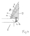
- Fig. 4 a section according to the invention analog Fig. 3
- Fig. 5 a and Fig. 5b Represent views of the leading segments according to the invention.
- Fig. 1 shows an inlet spiral 1 of a water turbine, in which the invention is used. This consists of a number of segments 2, the cross-sectional area decreases in the circumferential direction from the inlet ago.
- the inlet spiral 1 also has support blades 3, which are welded firmly to the support blade cheeks.
- Fig. 2 the region of the spiral 1 according to the prior art with support blade 3 and support blade cheek 4 and a guide element 5, which is designed here as a baffle, shown.
- the guide element 5 is cylindrical and attached via a plurality of circumferentially arranged and connected to the support blade cheek mounting ribs 6.
- Fig. 3 shows this attachment again in detail.
- Fig. 3 shows this attachment again in detail.
- Fig. 4 shows a section according to Fig. 3 with a guide segment 9 according to the invention. It can be seen here the contour 10 of the guide segments 9, which are adapted to the spiral skin 7. With the narrower cross-section of the spiral, the position of the spiral skin 7 'and the contour 10' of the corresponding guide segment 9 adapted thereto are obtained.
- the guide element is composed according to the invention of a plurality of guide segments 9, which are connected by screws 11 to the support blade cheek 4. The screws 11 are fixed in the guide segment 9 by a bush 12 and are secured in the support blade cheek 4 by a plug 13.
- the guide segments 9 are made of plastic, wherein the socket 12 is already poured during casting. There are several possibilities for producing the guide segments 9 according to the invention.
- the existing plastic guide segments 9 can be generated by a potting on the site.
- the bushes 12 for screwing through the support blade cheek 4 are screwed here in advance with the retaining screws 11.
- the individual guide segments then have the appropriate shape and there are no cavities between the guide segment 9 and spiral skin 7.
- the guide segments can be cast in a mold that is the same for all segments and subsequently by machining to the circumferentially changing contour of the Spiral skin 7, 7 'are adjusted.
- the sockets 12 for screwing with the support blade cheek 4 are also cast here with the same. It is also possible here to optimize the casting volume with a view to saving material.
- the guide segments 9 can also be produced by milling from a semifinished product, for example on a CNC milling machine.
- the sockets 12 a cutout 13 (see Fig. 5a, 5b ), in which the sockets 12 are used for screwing before mounting. It can also ring segments and cylinders made of plastic for forming a guide segment 9 are welded, with an additional welding of stiffening ribs is possible.
- Fig. 5a shows a 3-D view of a guide segment 9 of plastic according to the invention from the spiral side, wherein here, the milling cutouts 13 are also shown as an example by milling from a semifinished product. When casting the guide segments 9, of course, the cutouts 13 omitted.
- Fig. 5b shows the 3-D view from the water side. From these figures, an optimization of the volume can be seen.
Landscapes
- Engineering & Computer Science (AREA)
- Chemical & Material Sciences (AREA)
- Combustion & Propulsion (AREA)
- Mechanical Engineering (AREA)
- General Engineering & Computer Science (AREA)
- Structures Of Non-Positive Displacement Pumps (AREA)
Description
- Die Erfindung betrifft ein Spiralgehäuse einer Strömungsmaschine, insbesondere Turbine, Pumpe oder Pumpturbine, die aus einer Anzahl von in Umfangsrichtung hintereinander angeordneten und an den jeweiligen Stirnseiten miteinander verbundenen Segmenten besteht, mit Leiteinrichtungen am Einlauf zu den Stützschaufeln. Weiters betrifft die Erfindung ein Verfahren zur Fertigung eines Spiralgehäuses einer Strömungsmaschine und deren Leiteinrichtungen.
- Derartige Spiralgehäuse sind z.B. aus der
DE-AS 1 258 360 bekannt. Die Stützschaufelwangen (Vorleitschaufelringkränze) werden hier als Parallelplatte ausgeführt. Zur Verbesserung des hydraulischen Wirkungsgrades werden Leitbleche aus Stahl eingesetzt, die mittels Verschraubung an angeschweißten Rippen befestigt sind. Diese Leitbleche weisen einige Nachteile auf. Aufgrund der relativ hohen Ungenauigkeit bei Aussagen zur hydraulischen Belastung der Leitbleche ist die bisherige Konstruktion anfällig für Kerbspannungen, die unter der vorliegenden dynamischen Belastung zu einem Risswachstum und damit Versagen der Leitbleche führen können. Weiters kann es bei einem Versagen der Befestigung der Leitbleche zu einem größeren Schaden in der Turbine kommen.
Ziel der Erfindung ist es, eine Verbesserung des hydraulischen Wirkungsgrades bei gleichzeitiger Reduktion der Schadensanfälligkeit zu erreichen.
Die Erfindung ist daher dadurch gekennzeichnet, dass einzelne Leitsegmente vorgesehen sind, die aus Kunststoff bestehen.
Durch die Fertigung der einzelnen Leitsegmente aus Kunststoff kann die Schadenshäufigkeit einerseits und die Schadenshöhe andererseits wesentlich reduziert werden.
Eine günstige Weiterbildung der Erfindung ist dadurch gekennzeichnet, dass die Leitsegmente aus Kunststoff gegossen sind. Dadurch ist eine einfache und kostengünstige Herstellung der Leitsegmente möglich.
Eine günstige Ausgestaltung der Erfindung ist dadurch gekennzeichnet, dass die Leitsegmente mit der am Einlauf der Stützschaufel angeordneten Stützschaufelwange verschraubt sind, wobei die Leitsegmente Buchsen zur Verschraubung aufweisen können.
Eine günstige Weiterbildung der Erfindung ist dadurch gekennzeichnet, dass die Leitsegmente an die Form des Spiralgehäuses angepasst sind. Dadurch weisen die einzelnen Leitelementsegmente dann die passende Form auf.
Die Erfindung betrifft auch ein Verfahren zur Fertigung eines Spiralgehäuses einer Strömungsmaschine und deren Leiteinrichtungen. Es ist erfindungsgemäß dadurch gekennzeichnet, dass Leitsegmente aus Kunststoff gegossen werden. Dadurch ist eine einfache und kostengünstige Herstellung der Leitsegmente möglich.
Eine vorteilhafte Weiterbildung der Erfindung ist dadurch gekennzeichnet, dass im Spiralgehäuse eine Verschalung, insbesondere segmentweise, angebracht und mit Kunststoff ausgegossen wird, wodurch Leitsegmente geformt werden, wobei die erzeugten Leitsegmente anschließend aus der Verschalung entnommen und verputzt werden können.
Eine günstige Ausgestaltung der Erfindung ist dadurch gekennzeichnet, dass die Leitsegmente mit der am Einlauf der Stützschaufel angeordneten Stützschaufelwange verschraubt werden.
Eine alternative Ausgestaltung des erfindungsgemäßen Verfahrens ist dadurch gekennzeichnet, dass die Leitsegmente in einer Form gegossen werden, wobei die gegossenen Leitsegmente durch mechanische Bearbeitung an die sich umlaufend verändernde Spiralkontur angepasst werden können. Durch das Giessen der Segmente in eine Form, die für alle Segmente gleich ist und eine nachträgliche Anpassung an die Spiralkontur, ist eine Optimierung der Kosten (Serienfertigung) sowie auch des Gussvolumens mit Hinblick auf Materialeinsparung möglich. - Die Erfindung wird nun anhand der Zeichnungen beispielhaft beschrieben, wobei
Fig. 1 eine Einlaufspirale einer Wasserturbine, bei der die Erfindung eingesetzt wird,Fig. 2 den Bereich der Spirale mit Stützschaufel und Stützschaufelwange sowie einem Leitelement nach dem Stand der Technik,Fig. 3 einen Ausschnitt ausFig. 2 ,Fig. 4 einen Ausschnitt gemäß der Erfindung analogFig. 3 ,Fig. 5 a undFig. 5b Ansichten der Leitsegmente gemäß der Erfindung darstellen. -
Fig. 1 zeigt eine Einlaufspirale 1 einer Wasserturbine, bei der die Erfindung eingesetzt wird. Diese besteht aus einer Anzahl von Segmenten 2, deren Querschnittsfläche in Umfangrichtung vom Einlauf her abnimmt. Die Einlaufspirale 1 weist auch Stützschaufeln 3 auf, die fix mit den Stützschaufelwangen verschweisst sind. InFig. 2 ist der Bereich der Spirale 1 nach dem Stand der Technik mit Stützschaufel 3 und Stützschaufelwange 4 sowie einem Leitelement 5, das hier als Leitblech ausgebildet ist, dargestellt. Das Leitelement 5 ist zylinderförmig ausgeführt und über mehrere am Umfang angeordnete und mit der Stützschaufelwange verbundene Befestigungsrippen 6 befestigt.Fig. 3 zeigt diese Befestigung nochmals im Detail. Hier ist auch sehr deutlich der in Umfangsrichtung variierende Querschnitt der Spiralhaut 7 zu sehen. Problematisch bei dieser Ausführung ist auch, dass durch schwankende Drücke beim Wasserzustrom im Einlauf die Gefahr besteht, dass sich die Befestigungsschrauben 8 lockern und herausfallen. Durch die losen Leitbleche können Zerstörungen in der Turbine entstehen. Weiters wird der Wirkungsgrad der Anlage durch das dann nicht mehr korrekt befestigte Leitblech 5 reduziert. -
Fig. 4 zeigt einen Ausschnitt gemäßFig. 3 mit einem erfindungsgemäßen Leitsegment 9. Man erkennt hier die Kontur 10 der Leitsegmente 9, die an die Spiralhaut 7 angepasst sind. Beim engeren Querschnitt der Spirale ergibt sich die Position der Spiralhaut 7' und die daran angepasste Kontur 10' des entsprechenden Leitsegmentes 9.
Das Leitelement setzt sich erfindungsgemäß aus einer Vielzahl von Leitsegmenten 9 zusammen, die mittels Schrauben 11 mit der Stützschaufelwange 4 verbunden sind. Die Schrauben 11 sind im Leitsegment 9 durch eine Buchse 12 fixiert und werden in der Stützschaufelwange 4 durch einen Stopfen 13 gesichert. Die Leitsegmente 9 bestehen aus Kunststoff, wobei beim Gießen die Buchse 12 bereits eingegossen wird.
Zur Herstellung der erfindungsgemäßen Leitsegmente 9 gibt es mehrere Möglichkeiten.
Die aus Kunststoff bestehenden Leitsegmente 9 können durch einen Verguss auf der Baustelle erzeugt werden. Die Buchsen 12 zur Verschraubung durch die Stützschaufelwange 4 werden hier vorab mit den Halteschrauben 11 verschraubt. Es erfolgt eine segmentweise Verschalung in der Spirale 1, die mit Kunststoff ausgegossen wird, wobei vor dem Verguss ein Trennmittel auf die Innenseite der Spiralhaut 7 und Stützschaufelwange 4 aufgebracht wird, um die Leitsegmente nach dem Verguss aus dieser Form zu entnehmen und entsprechend für die Endmontage vorzubereiten. Dadurch weisen die einzelnen Leitsegmente dann die passende Form auf und es gibt keinerlei Hohlräume zwischen Leitsegment 9 und Spiralhaut 7. Alternativ können die Leitsegmente in einer Form gegossen werden, die für alle Segmente gleich ist und nachträglich durch mechanische Bearbeitung an die sich umlaufend ändernde Kontur der Spiralhaut 7, 7' angepasst werden. Die Buchsen 12 zur Verschraubung mit der Stützschaufelwange 4 werden hier ebenfalls gleich mit eingegossen. Es ist hier auch eine Optimierung des Gussvolumens mit Hinblick auf eine Materialeinsparung möglich. - Die Leitsegmente 9 können auch durch Fräsen aus einem Halbzeug z.B. auf einer CNC Fräsmaschine, erzeugt werden. Hier ist für die Buchsen 12 eine Ausfräsung 13 (siehe
Fig. 5a, 5b ) vorzusehen, in die die Buchsen 12 zur Verschraubung vor der Montage eingesetzt werden. Es können auch Ringsegmente und Zylinder aus Kunststoff zur Formung eines Leitsegmentes 9 verschweißt werden, wobei auch ein zusätzliches Einschweißen von Aussteifungsrippen möglich ist.
Fig. 5a zeigt eine 3-D-Ansicht eines erfindungsgemäßen Leitsegmentes 9 aus Kunststoff von der Spiralseite, wobei hier auch beispielhaft die Aüsfräsungen 13 bei einer Herstellung durch Fräsen aus einem Halbzeug dargestellt sind. Beim Gießen der Leitsegmente 9 entfallen natürlich die Ausfräsungen 13.
Fig. 5b zeigt die 3-D-Ansicht von der Wasserseite. Aus diesen Figuren ist auch eine Optimierung des Volumens erkennbar.
Claims (10)
- Spiralgehäuse einer Strömungsmaschine, insbesondere Turbine, Pumpe oder Pumpturbine, die aus einer Anzahl von in Umfangsrichtung hintereinander angeordneten und an den jeweiligen Stirnseiten miteinander verbundenen Segmenten (2) besteht, mit Leiteinrichtungen am Einlauf zu den Stützschaufeln (3), dadurch gekennzeichnet, dass einzelne Leitsegmente (9) vorgesehen sind, die aus Kunststoff bestehen.
- Spiralgehäuse nach Anspruch 1, dadurch gekennzeichnet, dass die Leitsegmente (9) aus Kunststoff gegossen sind.
- Spiralgehäuse nach einem der Ansprüche 1 oder 2, dadurch gekennzeichnet, dass die Leitsegmente (9) mit der am Einlauf der Stützschaufel (3) angeordneten Stützschaufelwange (4) verschraubt sind.
- Spiralgehäuse nach Anspruch 3, dadurch gekennzeichnet, dass die Leitsegmente (9) Buchsen (12) zur Verschraubung aufweisen.
- Spiralgehäuse nach einem der Ansprüche 1 bis 4, dadurch gekennzeichnet, dass die Leitsegmente (9) an die Form des Spiralgehäuses (1) angepasst sind.
- Verfahren zur Fertigung eines Spiralgehäuses einer Strömungsmaschine und deren Leiteinrichtungen nach Anspruch 1, dadurch gekennzeichnet, dass die Leitsegmente (9) aus Kunststoff gegossen werden.
- Verfahren nach Anspruch 6, dadurch gekennzeichnet, dass im Spiralgehäuse (1) eine Verschalung, insbesondere segmentweise, angebracht und mit Kunststoff ausgegossen wird, wodurch die Leitsegmente (9) geformt werden.
- Verfahren nach Anspruch 7, dadurch gekennzeichnet, dass die Leitsegmente (9) mit der am Einlauf der Stützschaufel (3) angeordneten Stützschaufelwange (4) verschraubt werden.
- Verfahren nach Anspruch 6, dadurch gekennzeichnet, dass die Leitsegmente (9) in einer Form gegossen werden.
- Verfahren nach Anspruch 9, dadurch gekennzeichnet, dass die gegossenen Leitsegmente (9) durch mechanische Bearbeitung an die sich umlaufend verändernde Spiralkontur (7, 7') angepasst werden.
Applications Claiming Priority (2)
| Application Number | Priority Date | Filing Date | Title |
|---|---|---|---|
| ATA2083/2010A AT510878B1 (de) | 2010-12-17 | 2010-12-17 | Spiralgehäuse einer strömungsmaschine und verfahren zur fertigung eines spiralgehäuses einer strömungsmaschine |
| PCT/AT2011/000486 WO2012079098A1 (de) | 2010-12-17 | 2011-12-06 | Spiralgehäuse einer strömungsmaschine und verfahren zur fertigung eines spiralgehäuses einer strömungsmaschine |
Publications (2)
| Publication Number | Publication Date |
|---|---|
| EP2652313A1 EP2652313A1 (de) | 2013-10-23 |
| EP2652313B1 true EP2652313B1 (de) | 2015-02-11 |
Family
ID=45463118
Family Applications (1)
| Application Number | Title | Priority Date | Filing Date |
|---|---|---|---|
| EP11805368.5A Not-in-force EP2652313B1 (de) | 2010-12-17 | 2011-12-06 | Spiralgehäuse einer strömungsmaschine und verfahren zur fertigung eines spiralgehäuses einer strömungsmaschine |
Country Status (9)
| Country | Link |
|---|---|
| EP (1) | EP2652313B1 (de) |
| CN (1) | CN103328813A (de) |
| AT (1) | AT510878B1 (de) |
| BR (1) | BR112013014950A2 (de) |
| CA (1) | CA2820992A1 (de) |
| ES (1) | ES2535953T3 (de) |
| MX (1) | MX2013006721A (de) |
| PT (1) | PT2652313E (de) |
| WO (1) | WO2012079098A1 (de) |
Family Cites Families (9)
| Publication number | Priority date | Publication date | Assignee | Title |
|---|---|---|---|---|
| DE1066149B (de) * | 1959-09-24 | |||
| GB254464A (en) * | 1925-05-13 | 1926-07-08 | English Electric Co Ltd | An improved construction of casing for hydraulic turbines and for other purposes |
| US1762121A (en) * | 1928-02-29 | 1930-06-03 | Allis Chalmers Mfg Co | Hydraulic machine |
| CH322758A (fr) * | 1955-02-14 | 1957-06-30 | Charmilles Sa Ateliers | Bâche spirale de machine hydraulique |
| DE1258360B (de) | 1962-09-15 | 1968-01-04 | Voith Gmbh J M | Spiralgehaeuse fuer Stroemungsmaschinen, insbesondere Turbinen, Pumpen oder Pumpenturbinen |
| SE401022C (sv) * | 1976-03-30 | 1982-01-18 | Karlstad Mekaniska Ab | Stagkrans for turbiner, pumpturbiner och pumpar |
| GB9218115D0 (en) * | 1992-08-26 | 1992-10-14 | Formulated Resins Ltd | Hard composition |
| WO2010122026A1 (en) * | 2009-04-22 | 2010-10-28 | Dsm Ip Assets B.V. | Plastic housing of a radial flow compressor |
| CN101786143B (zh) * | 2010-03-02 | 2012-05-02 | 中国农业大学 | 一种微型水轮机蜗壳和座环的可调模具 |
-
2010
- 2010-12-17 AT ATA2083/2010A patent/AT510878B1/de not_active IP Right Cessation
-
2011
- 2011-12-06 CN CN201180060932XA patent/CN103328813A/zh active Pending
- 2011-12-06 BR BR112013014950A patent/BR112013014950A2/pt not_active IP Right Cessation
- 2011-12-06 CA CA2820992A patent/CA2820992A1/en not_active Abandoned
- 2011-12-06 EP EP11805368.5A patent/EP2652313B1/de not_active Not-in-force
- 2011-12-06 MX MX2013006721A patent/MX2013006721A/es not_active Application Discontinuation
- 2011-12-06 ES ES11805368.5T patent/ES2535953T3/es active Active
- 2011-12-06 WO PCT/AT2011/000486 patent/WO2012079098A1/de not_active Ceased
- 2011-12-06 PT PT118053685T patent/PT2652313E/pt unknown
Also Published As
| Publication number | Publication date |
|---|---|
| EP2652313A1 (de) | 2013-10-23 |
| MX2013006721A (es) | 2013-09-13 |
| AT510878A1 (de) | 2012-07-15 |
| AT510878B1 (de) | 2013-02-15 |
| WO2012079098A1 (de) | 2012-06-21 |
| BR112013014950A2 (pt) | 2016-09-13 |
| CA2820992A1 (en) | 2012-06-21 |
| CN103328813A (zh) | 2013-09-25 |
| ES2535953T3 (es) | 2015-05-19 |
| PT2652313E (pt) | 2015-06-03 |
Similar Documents
| Publication | Publication Date | Title |
|---|---|---|
| EP2329150B1 (de) | Axiale strömungsmaschine mit asymmetrischem verdichtereintrittsleitgitter | |
| EP2886961B1 (de) | Unterlegscheibe einer Brennkammerschindel einer Gasturbine | |
| EP2035694B1 (de) | Rotornabe einer windenergieanlage | |
| EP2725193B1 (de) | Verfahren zur Verstimmung der Schaufeln eines Gasturbinenkraftwerks. | |
| EP1985803A1 (de) | Verfahren zum Herstellen von beschichteten Turbinenlaufschaufeln | |
| EP3803104B1 (de) | Windenergieanlagen-rotorblatt | |
| WO2012045609A1 (de) | Verfahren zur herstellung eines turboladergehäuses | |
| EP2617945B1 (de) | Rotor für eine Strömungsmaschine sowie Verfahren zu dessen Herstellung | |
| DE102008037554A1 (de) | Schwalbenschwanzbefestigung zur Verwendung mit Turbinenanordnungen und Verfahren zur Montage von Turbinenanordnungen | |
| EP2268902A1 (de) | Strebe für ein turbinenzwischengehäuse, turbinenzwischengehäuse und verfahren zur herstellung eines turbinenzwischengehäuses | |
| EP1022439B1 (de) | Gehäuse für eine Dampf- oder eine Gasturbine | |
| EP3559417B1 (de) | Verfahren zum herstellen eines windenergieanlagen-rotorblattes und windenergieanlagen-rotorblatt | |
| EP2505851A2 (de) | Stator einer Axialverdichterstufe einer Turbomaschine | |
| EP3390784B1 (de) | Strömungsmaschine mit mehreren leitschaufelstufen und verfahren zur teilweisen demontage einer solchen strömungsmaschine | |
| AT519606B1 (de) | Lagerdeckel | |
| EP2505784A1 (de) | Rotor für eine Turbomaschine und zugehöriges Modernisierungsverfahren | |
| AT510878B1 (de) | Spiralgehäuse einer strömungsmaschine und verfahren zur fertigung eines spiralgehäuses einer strömungsmaschine | |
| EP2992588B1 (de) | Synchrongenerator-stator und synchrongenerator | |
| DE60002781T2 (de) | Nabe-Achse Verbindung | |
| EP3421229A1 (de) | Verfahren zum positionieren von faserbauteilen | |
| DE19544188C2 (de) | Hydrodynamischer Retarder oder hydrodynamische Kupplung | |
| DE102010047612A1 (de) | Laufrad als Verdichter- oder Turbinenrad | |
| AT413427B (de) | Leitschaufelgehäuse einer pumpenstufe | |
| EP1617086B1 (de) | Tragstrebe für Schutzgitter und Verfahren zu ihrer Herstellung | |
| EP3362648B1 (de) | Verfahren zum herstellen eines grundkörpers einer turbinenschaufel |
Legal Events
| Date | Code | Title | Description |
|---|---|---|---|
| PUAI | Public reference made under article 153(3) epc to a published international application that has entered the european phase |
Free format text: ORIGINAL CODE: 0009012 |
|
| 17P | Request for examination filed |
Effective date: 20130710 |
|
| AK | Designated contracting states |
Kind code of ref document: A1 Designated state(s): AL AT BE BG CH CY CZ DE DK EE ES FI FR GB GR HR HU IE IS IT LI LT LU LV MC MK MT NL NO PL PT RO RS SE SI SK SM TR |
|
| DAX | Request for extension of the european patent (deleted) | ||
| GRAP | Despatch of communication of intention to grant a patent |
Free format text: ORIGINAL CODE: EPIDOSNIGR1 |
|
| INTG | Intention to grant announced |
Effective date: 20140819 |
|
| GRAS | Grant fee paid |
Free format text: ORIGINAL CODE: EPIDOSNIGR3 |
|
| GRAA | (expected) grant |
Free format text: ORIGINAL CODE: 0009210 |
|
| AK | Designated contracting states |
Kind code of ref document: B1 Designated state(s): AL AT BE BG CH CY CZ DE DK EE ES FI FR GB GR HR HU IE IS IT LI LT LU LV MC MK MT NL NO PL PT RO RS SE SI SK SM TR |
|
| REG | Reference to a national code |
Ref country code: GB Ref legal event code: FG4D Free format text: NOT ENGLISH |
|
| REG | Reference to a national code |
Ref country code: CH Ref legal event code: EP |
|
| REG | Reference to a national code |
Ref country code: IE Ref legal event code: FG4D Free format text: LANGUAGE OF EP DOCUMENT: GERMAN |
|
| REG | Reference to a national code |
Ref country code: AT Ref legal event code: REF Ref document number: 710019 Country of ref document: AT Kind code of ref document: T Effective date: 20150315 |
|
| REG | Reference to a national code |
Ref country code: DE Ref legal event code: R096 Ref document number: 502011005871 Country of ref document: DE Effective date: 20150326 |
|
| REG | Reference to a national code |
Ref country code: ES Ref legal event code: FG2A Ref document number: 2535953 Country of ref document: ES Kind code of ref document: T3 Effective date: 20150519 |
|
| REG | Reference to a national code |
Ref country code: PT Ref legal event code: SC4A Free format text: AVAILABILITY OF NATIONAL TRANSLATION Effective date: 20150429 |
|
| REG | Reference to a national code |
Ref country code: NL Ref legal event code: VDEP Effective date: 20150211 |
|
| REG | Reference to a national code |
Ref country code: NO Ref legal event code: T2 Effective date: 20150211 |
|
| REG | Reference to a national code |
Ref country code: LT Ref legal event code: MG4D |
|
| PG25 | Lapsed in a contracting state [announced via postgrant information from national office to epo] |
Ref country code: LT Free format text: LAPSE BECAUSE OF FAILURE TO SUBMIT A TRANSLATION OF THE DESCRIPTION OR TO PAY THE FEE WITHIN THE PRESCRIBED TIME-LIMIT Effective date: 20150211 Ref country code: HR Free format text: LAPSE BECAUSE OF FAILURE TO SUBMIT A TRANSLATION OF THE DESCRIPTION OR TO PAY THE FEE WITHIN THE PRESCRIBED TIME-LIMIT Effective date: 20150211 Ref country code: FI Free format text: LAPSE BECAUSE OF FAILURE TO SUBMIT A TRANSLATION OF THE DESCRIPTION OR TO PAY THE FEE WITHIN THE PRESCRIBED TIME-LIMIT Effective date: 20150211 Ref country code: SE Free format text: LAPSE BECAUSE OF FAILURE TO SUBMIT A TRANSLATION OF THE DESCRIPTION OR TO PAY THE FEE WITHIN THE PRESCRIBED TIME-LIMIT Effective date: 20150211 |
|
| PG25 | Lapsed in a contracting state [announced via postgrant information from national office to epo] |
Ref country code: RS Free format text: LAPSE BECAUSE OF FAILURE TO SUBMIT A TRANSLATION OF THE DESCRIPTION OR TO PAY THE FEE WITHIN THE PRESCRIBED TIME-LIMIT Effective date: 20150211 Ref country code: LV Free format text: LAPSE BECAUSE OF FAILURE TO SUBMIT A TRANSLATION OF THE DESCRIPTION OR TO PAY THE FEE WITHIN THE PRESCRIBED TIME-LIMIT Effective date: 20150211 Ref country code: GR Free format text: LAPSE BECAUSE OF FAILURE TO SUBMIT A TRANSLATION OF THE DESCRIPTION OR TO PAY THE FEE WITHIN THE PRESCRIBED TIME-LIMIT Effective date: 20150512 Ref country code: NL Free format text: LAPSE BECAUSE OF FAILURE TO SUBMIT A TRANSLATION OF THE DESCRIPTION OR TO PAY THE FEE WITHIN THE PRESCRIBED TIME-LIMIT Effective date: 20150211 |
|
| PG25 | Lapsed in a contracting state [announced via postgrant information from national office to epo] |
Ref country code: CZ Free format text: LAPSE BECAUSE OF FAILURE TO SUBMIT A TRANSLATION OF THE DESCRIPTION OR TO PAY THE FEE WITHIN THE PRESCRIBED TIME-LIMIT Effective date: 20150211 Ref country code: RO Free format text: LAPSE BECAUSE OF FAILURE TO SUBMIT A TRANSLATION OF THE DESCRIPTION OR TO PAY THE FEE WITHIN THE PRESCRIBED TIME-LIMIT Effective date: 20150211 Ref country code: SK Free format text: LAPSE BECAUSE OF FAILURE TO SUBMIT A TRANSLATION OF THE DESCRIPTION OR TO PAY THE FEE WITHIN THE PRESCRIBED TIME-LIMIT Effective date: 20150211 Ref country code: DK Free format text: LAPSE BECAUSE OF FAILURE TO SUBMIT A TRANSLATION OF THE DESCRIPTION OR TO PAY THE FEE WITHIN THE PRESCRIBED TIME-LIMIT Effective date: 20150211 Ref country code: EE Free format text: LAPSE BECAUSE OF FAILURE TO SUBMIT A TRANSLATION OF THE DESCRIPTION OR TO PAY THE FEE WITHIN THE PRESCRIBED TIME-LIMIT Effective date: 20150211 |
|
| REG | Reference to a national code |
Ref country code: DE Ref legal event code: R097 Ref document number: 502011005871 Country of ref document: DE |
|
| PG25 | Lapsed in a contracting state [announced via postgrant information from national office to epo] |
Ref country code: PL Free format text: LAPSE BECAUSE OF FAILURE TO SUBMIT A TRANSLATION OF THE DESCRIPTION OR TO PAY THE FEE WITHIN THE PRESCRIBED TIME-LIMIT Effective date: 20150211 |
|
| PLBE | No opposition filed within time limit |
Free format text: ORIGINAL CODE: 0009261 |
|
| STAA | Information on the status of an ep patent application or granted ep patent |
Free format text: STATUS: NO OPPOSITION FILED WITHIN TIME LIMIT |
|
| PG25 | Lapsed in a contracting state [announced via postgrant information from national office to epo] |
Ref country code: IT Free format text: LAPSE BECAUSE OF FAILURE TO SUBMIT A TRANSLATION OF THE DESCRIPTION OR TO PAY THE FEE WITHIN THE PRESCRIBED TIME-LIMIT Effective date: 20150211 |
|
| 26N | No opposition filed |
Effective date: 20151112 |
|
| PG25 | Lapsed in a contracting state [announced via postgrant information from national office to epo] |
Ref country code: SI Free format text: LAPSE BECAUSE OF FAILURE TO SUBMIT A TRANSLATION OF THE DESCRIPTION OR TO PAY THE FEE WITHIN THE PRESCRIBED TIME-LIMIT Effective date: 20150211 |
|
| PG25 | Lapsed in a contracting state [announced via postgrant information from national office to epo] |
Ref country code: BE Free format text: LAPSE BECAUSE OF NON-PAYMENT OF DUE FEES Effective date: 20151231 |
|
| REG | Reference to a national code |
Ref country code: DE Ref legal event code: R119 Ref document number: 502011005871 Country of ref document: DE |
|
| PG25 | Lapsed in a contracting state [announced via postgrant information from national office to epo] |
Ref country code: LU Free format text: LAPSE BECAUSE OF FAILURE TO SUBMIT A TRANSLATION OF THE DESCRIPTION OR TO PAY THE FEE WITHIN THE PRESCRIBED TIME-LIMIT Effective date: 20151206 Ref country code: MC Free format text: LAPSE BECAUSE OF FAILURE TO SUBMIT A TRANSLATION OF THE DESCRIPTION OR TO PAY THE FEE WITHIN THE PRESCRIBED TIME-LIMIT Effective date: 20150211 |
|
| REG | Reference to a national code |
Ref country code: CH Ref legal event code: PL |
|
| REG | Reference to a national code |
Ref country code: NO Ref legal event code: MMEP |
|
| GBPC | Gb: european patent ceased through non-payment of renewal fee |
Effective date: 20151206 |
|
| REG | Reference to a national code |
Ref country code: IE Ref legal event code: MM4A |
|
| REG | Reference to a national code |
Ref country code: FR Ref legal event code: ST Effective date: 20160831 |
|
| PG25 | Lapsed in a contracting state [announced via postgrant information from national office to epo] |
Ref country code: GB Free format text: LAPSE BECAUSE OF NON-PAYMENT OF DUE FEES Effective date: 20151206 Ref country code: NO Free format text: LAPSE BECAUSE OF NON-PAYMENT OF DUE FEES Effective date: 20151231 Ref country code: LI Free format text: LAPSE BECAUSE OF NON-PAYMENT OF DUE FEES Effective date: 20151231 Ref country code: IE Free format text: LAPSE BECAUSE OF NON-PAYMENT OF DUE FEES Effective date: 20151206 Ref country code: CH Free format text: LAPSE BECAUSE OF NON-PAYMENT OF DUE FEES Effective date: 20151231 Ref country code: DE Free format text: LAPSE BECAUSE OF NON-PAYMENT OF DUE FEES Effective date: 20160701 |
|
| PG25 | Lapsed in a contracting state [announced via postgrant information from national office to epo] |
Ref country code: FR Free format text: LAPSE BECAUSE OF NON-PAYMENT OF DUE FEES Effective date: 20151231 Ref country code: PT Free format text: LAPSE BECAUSE OF NON-PAYMENT OF DUE FEES Effective date: 20160907 |
|
| REG | Reference to a national code |
Ref country code: ES Ref legal event code: FD2A Effective date: 20170126 |
|
| PG25 | Lapsed in a contracting state [announced via postgrant information from national office to epo] |
Ref country code: ES Free format text: LAPSE BECAUSE OF NON-PAYMENT OF DUE FEES Effective date: 20151207 |
|
| PG25 | Lapsed in a contracting state [announced via postgrant information from national office to epo] |
Ref country code: BG Free format text: LAPSE BECAUSE OF FAILURE TO SUBMIT A TRANSLATION OF THE DESCRIPTION OR TO PAY THE FEE WITHIN THE PRESCRIBED TIME-LIMIT Effective date: 20150211 Ref country code: SM Free format text: LAPSE BECAUSE OF FAILURE TO SUBMIT A TRANSLATION OF THE DESCRIPTION OR TO PAY THE FEE WITHIN THE PRESCRIBED TIME-LIMIT Effective date: 20150211 Ref country code: HU Free format text: LAPSE BECAUSE OF FAILURE TO SUBMIT A TRANSLATION OF THE DESCRIPTION OR TO PAY THE FEE WITHIN THE PRESCRIBED TIME-LIMIT; INVALID AB INITIO Effective date: 20111206 |
|
| PG25 | Lapsed in a contracting state [announced via postgrant information from national office to epo] |
Ref country code: IS Free format text: LAPSE BECAUSE OF NON-PAYMENT OF DUE FEES Effective date: 20160630 Ref country code: CY Free format text: LAPSE BECAUSE OF FAILURE TO SUBMIT A TRANSLATION OF THE DESCRIPTION OR TO PAY THE FEE WITHIN THE PRESCRIBED TIME-LIMIT Effective date: 20150211 |
|
| PG25 | Lapsed in a contracting state [announced via postgrant information from national office to epo] |
Ref country code: MT Free format text: LAPSE BECAUSE OF FAILURE TO SUBMIT A TRANSLATION OF THE DESCRIPTION OR TO PAY THE FEE WITHIN THE PRESCRIBED TIME-LIMIT Effective date: 20150211 |
|
| REG | Reference to a national code |
Ref country code: AT Ref legal event code: MM01 Ref document number: 710019 Country of ref document: AT Kind code of ref document: T Effective date: 20161206 |
|
| PG25 | Lapsed in a contracting state [announced via postgrant information from national office to epo] |
Ref country code: AT Free format text: LAPSE BECAUSE OF NON-PAYMENT OF DUE FEES Effective date: 20161206 |
|
| PG25 | Lapsed in a contracting state [announced via postgrant information from national office to epo] |
Ref country code: MK Free format text: LAPSE BECAUSE OF FAILURE TO SUBMIT A TRANSLATION OF THE DESCRIPTION OR TO PAY THE FEE WITHIN THE PRESCRIBED TIME-LIMIT Effective date: 20150211 |
|
| PG25 | Lapsed in a contracting state [announced via postgrant information from national office to epo] |
Ref country code: AL Free format text: LAPSE BECAUSE OF FAILURE TO SUBMIT A TRANSLATION OF THE DESCRIPTION OR TO PAY THE FEE WITHIN THE PRESCRIBED TIME-LIMIT Effective date: 20150211 |
|
| PG25 | Lapsed in a contracting state [announced via postgrant information from national office to epo] |
Ref country code: TR Free format text: LAPSE BECAUSE OF NON-PAYMENT OF DUE FEES Effective date: 20151206 |