EP2652233B1 - Vorrichtung zum befestigen der führrungsschiene enes behangs - Google Patents
Vorrichtung zum befestigen der führrungsschiene enes behangs Download PDFInfo
- Publication number
- EP2652233B1 EP2652233B1 EP13708871.2A EP13708871A EP2652233B1 EP 2652233 B1 EP2652233 B1 EP 2652233B1 EP 13708871 A EP13708871 A EP 13708871A EP 2652233 B1 EP2652233 B1 EP 2652233B1
- Authority
- EP
- European Patent Office
- Prior art keywords
- channel
- support
- rail
- elongate
- screen
- Prior art date
- Legal status (The legal status is an assumption and is not a legal conclusion. Google has not performed a legal analysis and makes no representation as to the accuracy of the status listed.)
- Not-in-force
Links
Images




Classifications
-
- E—FIXED CONSTRUCTIONS
- E06—DOORS, WINDOWS, SHUTTERS, OR ROLLER BLINDS IN GENERAL; LADDERS
- E06B—FIXED OR MOVABLE CLOSURES FOR OPENINGS IN BUILDINGS, VEHICLES, FENCES OR LIKE ENCLOSURES IN GENERAL, e.g. DOORS, WINDOWS, BLINDS, GATES
- E06B9/00—Screening or protective devices for wall or similar openings, with or without operating or securing mechanisms; Closures of similar construction
- E06B9/56—Operating, guiding or securing devices or arrangements for roll-type closures; Spring drums; Tape drums; Counterweighting arrangements therefor
- E06B9/58—Guiding devices
-
- E—FIXED CONSTRUCTIONS
- E06—DOORS, WINDOWS, SHUTTERS, OR ROLLER BLINDS IN GENERAL; LADDERS
- E06B—FIXED OR MOVABLE CLOSURES FOR OPENINGS IN BUILDINGS, VEHICLES, FENCES OR LIKE ENCLOSURES IN GENERAL, e.g. DOORS, WINDOWS, BLINDS, GATES
- E06B9/00—Screening or protective devices for wall or similar openings, with or without operating or securing mechanisms; Closures of similar construction
- E06B9/56—Operating, guiding or securing devices or arrangements for roll-type closures; Spring drums; Tape drums; Counterweighting arrangements therefor
- E06B9/58—Guiding devices
- E06B2009/587—Mounting of guiding devices to supporting structure
Definitions
- the present invention relates to a novel screen system employing a zip-like retention device such as a screen, a method of mounting the same, and particularly but not exclusively apparatus for mounting a rail for guiding one lateral side of a zip-like screen.
- the novel screen system comprises a particular form of roller blind and a pair of guide rails disposed on either side of an aperture to control blind position as it is deployed/retracted to cover/uncover the aperture.
- the blind fabric has flexible strips on its lateral sides which are trapped within, but free to slide along, a specially shaped groove or keyway in each of the rails.
- Each flexible strip typically is one half of a zipper, but could be manufactured by moulding a soft or semi-rigid high polymer such as hot-melt synthetic resin or rubber.
- a roller blind with such flexible strips for engaging corresponding rails is hereinafter referred to as a zip-like screen.
- US 4,638,844 discloses an early form of screen system, with a simple bracket for loosely mounting a guide rail.
- GB 2 235 005 discloses an improved bracket for loosely mounting a guide rail.
- Figures 1A and 1B show existing brackets for loosely mounting a guide rail.
- the bracket 10 of Figure 1A is configured to be secured to a surface forming part of the inner periphery of the aperture to be screened, whereas the bracket 20 of Figure 1B is configured to be secured via an additional flange 22 to a surface extending away from the aperture to be screened.
- Each bracket 10,20 comprises an aluminium extrusion 30 and a pair of clip-on strips of plastics material 32, which together define a channel 33 for receiving a rail 34 (shown in dotted lines).
- the rail 34 is supported within the channel 33 by pairs of resilient foam strips 36 which provide some flexibility and allow the depth D of the rail 34 within the channel 33 to vary if required.
- a blind system with a zip-like screen is only able to control blind position as it is deployed and retracted if the guide rails are correctly positioned. Even though the rails are loosely mounted in the brackets, a small angular misalignment of the brackets (leading to rails which are not parallel or skewed to one side) can result in blind creasing or jamming. The problem is exacerbated in such blind systems for apertures with a high aspect ratio. A novel bracket for preventing such misalignment was proposed in WO 2009/098433 . However, the success of the system relied upon careful installation by an experienced workman, so it did not lend itself to the mass DIY market. Accordingly, the present invention has been devised with a view to addressing or at least ameliorating this problem in a more user friendly way.
- apparatus for mounting a rail for guiding one lateral side of a zip-like screen comprising: an elongate body having a channel for receiving the rail, the channel having an open top extending in a first direction along the elongate body and a depth extending in a second direction from the open top towards an opposing base of the channel; and a support mechanism, configured to be positioned in the channel, for supporting the rail when received in the channel; characterised in that the support mechanism comprises at least one support member having a plurality of profiles spaced in the second direction when positioned in the channel, with each profile being configured to support the rail at a different depth in the channel.
- the or each support member enables the localised position (i.e. depth) of the rail within the channel to be adjusted during installation in order to achieve correct alignment with the one lateral side of the zip-like screen.
- the plurality of profiles of the or each support member may be configured to support the rail in one of at least two different depths in the channel, such as three or even four different depths in the channel.
- the support member(s) may be used to compensate for the misalignment and help ensure the zip-like screen is able to be guided by the rail without creasing or jamming.
- the at least one support member may comprise a resilient portion for resiliently supporting the rail when received in the channel.
- the resilient portion maybe configured to allow movement of the plurality of profiles towards the open top of the channel in response to an applied load on the rail tending to pull the rail towards the open top of the channel. The degree of such movement may be less than the span of the plurality of profiles in the second direction.
- the resilient portion may comprise a spring member.
- At least one side wall of the channel may be shaped to retain the at least one support member within the channel in use.
- the at least one side wall of the channel may include a groove extending therealong for engaging one side of the at least one support member.
- the at least one side of the at least one support member may be a sliding fit within the groove.
- the at least one side of the at least one support member may be resiliently biased within the groove by the resilient portion of the at least one support member.
- the elongate body may comprise a first elongate part and a second elongate part which in use is coupled to the first elongate part, with the first elongate part defining a first side wall of the channel and the second elongate part defining a second side wall of the channel.
- the first and second elongate parts may have interengageable profiles for releasably coupling the second elongate part to the first elongate part.
- the first elongate part may comprise a first wall inclined relative to a second wall, with each of the first and second walls being configured to receive a fixture therethrough for securing the first elongate part to a support surface.
- the first wall may be inclined at about 90° to the second wall.
- the first elongate part may be fitted to a support surface either forming part of the inner periphery of the aperture to be screened (e.g. a window reveal) or extending laterally away therefrom simply by using fixing means extending through the first or second walls.
- the first elongate part may have a substantially "L"-shaped cross-section, allowing unhindered access to each of the first and second walls.
- the second elongate part need only be coupled to the first elongate part once the latter has been secured in place and the support mechanism and rail have been put into position relative to the first elongate part.
- the support mechanism may comprise a pair of support members, each having a plurality of profiles spaced in the second direction when positioned in the channel and configured to support the rail at a different depth within the channel, the pair of support members being spaced apart in the first direction.
- the rail may be supported at a first depth in the channel by one of the pair of support members, and at a second depth in the channel by another of the pair of support members.
- the first and second depths may be the same or different. If the first and second depths are different, at least a portion of the rail will be supported at an angle within the channel.
- the pair of support members may be spaced apart using a solid spacer member configured to abut one side wall of the channel between the pair of support members.
- the solid spacer member may help to prevent light passing between the pair of support members which may be important if the zip-like screen is being used as a blackout blind.
- the solid spacer member may have at least one recess on one side which in use abuts the side wall of the channel, the at least one recess being configured to encourage localised deformation and countersinking of a screw driven through the solid spacer member from an opposing side, for example when securing the apparatus to a support surface.
- the at least one support member may have a substantially "U"-shaped cross section, and comprise a first support part and a second support part which in use engages the first support part, with each support part comprising complementary components of the plurality of profiles. With such an arrangement, the at least one support member may be introduced into the channel one part at a time.
- the first and second support parts may have male and female interengageable profiles for engaging the second support part to the first support part.
- the first and second support parts may be identical, with each part having both male and female interengageable profiles.
- a method of installing a screen system comprising: providing a zip-like screen which includes a blind mounted on a roller, the blind having flexible strips on each lateral side thereof, each of the flexible strips being configured to engage a keyway in a rail; mounting the zip-like screen with its roller in its intended position; providing the apparatus in accordance with a first aspect of the invention; mounting the elongate body of the apparatus to one side of the zip-like screen; selecting one of the profiles of the at least one support member which will maintain the rail at an appropriate depth within the channel to enable one lateral side of the blind to slidingly engage the keyway of the rail when coupled to the at least one support member; and coupling the rail to the selected profile of the at least one support member.
- the second aspect of the invention may comprise any of the features described with reference to the first aspect of the invention.
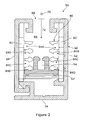
- FIG. 2 illustrates a cross-sectional view of apparatus 50 embodying the present invention which is configured to mount a rail 52 with a keyway 54 for guiding one lateral side of a zip-like screen (not shown).
- the apparatus 50 comprises an elongate body 60, comprising a first elongate part 62 and a second elongate part 64, having a channel 66 for receiving the rail 52.
- the channel 66 has an open top 68 extending in a first direction 70 along the elongate body (i.e. perpendicular to the page as shown in Figure 2 ), and a depth extending in a second direction 72 perpendicular to the first direction 70, from the open top 68 towards the opposing base 74 of the channel 66.
- the rail 52 is supported in the channel 66 by a support mechanism 80 comprising at least one support member 82 having a plurality of profiles 84A, 84B, 84C, 84D spaced in the second direction 72 when positioned in the channel 66.
- Each profile 84A, 84B, 84C, 84D is configured to support the rail 52 at a different depth in the channel 66.
- the support member 82 has four profiles 84A, 84B, 84C, 84D, with the rail 52 being supported by the lowest profile 84D in the deepest position within the channel 66.
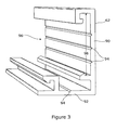
- the first elongate part 62 of the elongate body 60 is illustrated in Figure 3 .
- the first elongate comprises a first wall 90 and a second wall 92 angled at about 90° to the first wall 90, giving rise to an "L" -shaped cross section.
- Both the first and second walls 90, 92 include notches 94 for receiving screws when fixing one or other wall 90, 92 to a support surface.
- the first wall 90 of the first elongate part 62 defines a first side wall 96 of the channel 66.
- the first side wall 96 of the channel 66 includes a groove 98 for retaining the support mechanism 80 in the channel 66.
- each support member 82 of the support mechanism 82 has a substantially "U"-shaped cross-section in use and comprises a first support part 100 and a second support part 102.
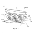
- the first and second support parts 100, 102 are identical, and thus each comprises a body 105 with complementary components 104 of the plurality of profiles 84A, 84B, 84C, 84D, together with both male and female connectors 106, 108 for releasably interconnecting the first and second support parts 100, 102 together.
- the structure of the first and second support parts 100, 102 is shown in more detail in Figure 5 .
- the components 104 of the profiles 84A, 84B, 84C, 84D are in the form of a series of tabs 110 projecting from the body 105.
- Each tab 110 has an enlarged leading portion 112 to define a constriction in the space between adjacent tabs 110.
- the body 105 includes a resilient portion provided in the form of spring member 114 which is configured to flex under an applied load L.
- the body 105 is a sliding fit in the groove 98 of the first elongate part 62.
- first support parts 100, 100' are introduced into the groove 98 of the first elongate part 62.
- the two first support parts 100, 100' are separated by a solid spacer member 120 which is also a sliding fit in the groove 98.
- the solid spacer member 120 not only maintains a minimum separation between the two first support parts 100, 100' during use, but also helps to block passage of light between the two first support parts 100, 100'.
- the first elongate part 62 may be fixed to a support surface 122 using screws 124 which pass through the solid spacer member 120.
- the marks 126 on the visible surface of the solid spacer member 120 register with the notches 94 to help with driving the screws through the wall 90.
- the marks 126 also register with recesses 128 on the underside of the solid spacer member 120, as shown in Figure 7 .
- the recesses 128 encourage local deformation of the solid spacer member 120 when driving screws therethrough to allow screw countersinking, without compromising the light blocking role of the solid spacer member 120.
- the next step in assembling the apparatus 50 involves coupling the rail52 to selected components 104 of the profiles 84A, 84B, 84C, 84D of the two first support parts 100, 100'.
- the rail 52 has a lateral flange 130 with an enlarged edge portion 132 which is configured to engage a space between the tabs 110 with a snap-fit action. When unconstrained, the rail 52 is able to flex along its length, meaning that it need not be installed parallel to the first elongate part 62.
- a first end 134 of the rail 52 may be urged into engagement with the components 104 of the profile 84A towards the top of the first support part 100, whereas a second end 136 of the rail 52 may be urged into engagement with the components 104 of the profile 84C towards the bottom of the first support part 100'. It may be necessary to incline the rail 52 relative to the first elongate part 62 in such a manner in order to ensure the zip-like screen is able to be guided by the rail 52 without creasing or jamming, as will be explained in more detail below.
- Figure 8 illustrates the rail 52 engaging the components 104 of the profile 84D of both the first support parts 100, 100', meaning that the rail 52 is parallel to the first elongate part 62.
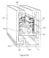
- two second support parts 102, 102' are coupled to the rail 52 as shown in Figure 9 .
- One second support part 102 is registered with the first support part 100, and the other second support part 102' is registered with the first support part 100'.
- the rail has a second lateral flange 140 with an enlarged edge portion 142 which is configured to engage a space between tabs 110 with a snap-fit action.
- corresponding pairs of male and female connectors 106, 108 interconnect.
- the assembly of the apparatus 50 is completed by coupling the second elongate part 64 to the first elongate part 62 using interengageable profiles 150, 152.
- the spring member 114 of each second support part 102, 102' is introduced into a groove 154 extending along an upper portion of the second elongate part 64.
- Pressure is applied to the second elongate part 64 to compress the spring members 114 to enable hook-like profile 152 extending along a lower portion of the second elongate part 64 to engage a corresponding hook-like profile 150 protruding from the second wall 94 of the first elongate part 62.
- a filler strip may be introduced into gap 156 to resist disengagement of the first and second elongate parts 62, 64.
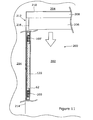
- a method of mounting the apparatus 50 to the inner periphery of a window reveal will now be described with reference to Figure 11 .
- a screen system 200 is to be used to screen a window 202 in a wall 204.
- the screen system 200 includes a zip-like screen 206 mounted on a roller in a housing 208.
- the housing is fixed horizontally to the underside 210 of the window reveal 212, and the first elongate part 62 (complete with the first support parts 100, 100' and spacer member 120) is fixed substantially vertically to one inner side 214 of the window reveal 212.
- Figure 11 only shows a section of the first elongate part 62; in practice, it would be longer and include many pairs of the first support parts 100, 100' and spacer member 120.
- the rail 52 is then coupled to the first support parts 100, 100' in exactly the correct position to ensure the zip-like screen 206 is able to be guided by the rail 52 without creasing or jamming.
- the first elongate part 62 will also be vertical and the rail 52 will be mounted vertically by engaging components 104 of the same profile (e.g. profile 84C) of each first support part 100, 100'.
- the inner side 214 of the window reveal 212 is slightly inclined to the vertical
- the first elongate part 62 may also be slightly inclined to the vertical. Nevertheless, the rail 52 may still be mounted vertically in the first elongate part 62 by coupling it to components 104 of different profiles (e.g. profile 84A and profile 84C) of the first support parts 100, 100'.
- the assembly of the apparatus may be completed as described with reference to Figures 2-10 .
- a corresponding assembly 50 is fixed to an opposing side of the window reveal 212.
- the zip-like screen is then ready to be guided as it is deployed/retracted.
- the spring members 114 of the first and second support parts 100, 100', 102, 102' are able to flex within the elongate body 60, allowing small lateral movements of the rail 52 relative to the first and second elongate parts 62, 64 to help keep the zip-like screen 206 taut without causing it to jam when deployed/retracted.
Landscapes
- Engineering & Computer Science (AREA)
- Structural Engineering (AREA)
- Architecture (AREA)
- Civil Engineering (AREA)
- Operating, Guiding And Securing Of Roll- Type Closing Members (AREA)
- Blinds (AREA)
- Curtains And Furnishings For Windows Or Doors (AREA)
Claims (15)
- Vorrichtung (50) zum Montieren einer Schiene (52) zum Führen einer lateralen Seite eines reißverschlussähnlichen Behangs, die Folgendes umfasst:einen länglichen Körper (60) mit einem Kanal (66) zur Aufnahme der Schiene (52), wobei der Kanal (66) eine in einer ersten Richtung (70) entlang dem länglichen Körper (60) verlaufende offene Oberseite (68) und eine Tiefe hat, die in einer zweiten Richtung (72) von der offenen Oberseite (68) in Richtung auf eine gegenüberliegende Basis (74) des Kanals (66) verläuft; undeinen Tragmechanismus (80), der zum Positionieren in dem Kanal (66) konfiguriert ist, zum Tragen der Schiene (52), wenn sie in dem Kanal (66) aufgenommen ist;dadurch gekennzeichnet, dass der Tragmechanismus (80) wenigstens ein Tragelement (82) mit mehreren Profilen (84A, 84B, 84C, 84D) umfasst, die in der zweiten Richtung (72) beabstandet sind, wenn sie in dem Kanal (66) positioniert sind, wobei jedes Profil zum Tragen der Schiene (52) in einer anderen Tiefe in dem Kanal (66) konfiguriert ist.
- Vorrichtung (50) nach Anspruch 1, wobei das wenigstens eine Tragelement (82) einen elastischen Abschnitt zum elastischen Tragen der Schiene (52) umfasst, wenn sie in dem Kanal (66) aufgenommen wird.
- Vorrichtung (50) nach Anspruch 2, wobei der elastische Teil ein Federelement (14) umfasst.
- Vorrichtung (50) nach einem der Ansprüche 1 bis 3, wobei wenigstens eine Seitenwand (96) des Kanals (66) zum Halten des wenigstens einen Tragelements (82) in dem Kanal beim Gebrauch geformt ist.
- Vorrichtung (50) nach Anspruch 4, wobei die wenigstens eine Seitenwand (96) des Kanals (66) eine Rille (98) aufweist, die daran entlang verläuft, um in eine Seite des wenigstens einen Tragelements (82) einzugreifen.
- Vorrichtung (50) nach einem der vorherigen Ansprüche, wobei der längliche Körper (60) einen ersten länglichen Teil (62) und einen zweiten länglichen Teil (64) umfasst, der beim Gebrauch mit dem ersten länglichen Teil (62) gekoppelt ist, wobei der erste längliche Teil (62) eine erste Seitenwand (96) des Kanals (66) definiert und der zweite längliche Teil (64) eine zweite Seitenwand des Kanals (66) definiert.
- Vorrichtung nach Anspruch 6, wobei der erste und der zweite längliche Teil (62, 64) ineinander eingreifbare Profile (150, 152) zum lösbaren Koppeln des zweiten länglichen Teils (64) am ersten länglichen Teil (62) aufweist.
- Vorrichtung (50) nach Anspruch 6 oder Anspruch 7, wobei der erste längliche Teil (62) eine erste Wand (90) umfasst, die relativ zu einer zweiten Wand (92) geneigt ist, wobei die erste und die zweite Wand (90, 92) jeweils zum Aufnehmen einer Befestigungsvorrichtung durch sie zum Befestigen des ersten länglichen Teils (62) an einer Tragfläche konfiguriert ist.
- Vorrichtung (50) nach einem der vorherigen Ansprüche, wobei der Tragmechanismus (80) ein Paar Tragelemente (82) umfasst, jeweils mit mehreren Profilen (84A, 84B, 84C, 84D), die in der zweiten Richtung (72) beabstandet sind, wenn sie in dem Kanal (66) positioniert sind, und zum Tragen der Schiene (52) in einer anderen Tiefe in dem Kanal (66) konfiguriert ist, wobei das Paar Tragelemente (82) in der ersten Richtung (70) beabstandet ist.
- Vorrichtung (50) nach Anspruch 9, wobei das Paar Tragelemente (82) mit einem festen Abstandshalterelement (120) beabstandet ist, das zum Anstoßen an einer Seitenwand (96) des Kanals (66) zwischen dem Paar Tragelementen (82) konfiguriert ist.
- Vorrichtung (50) nach Anspruch 10, wobei das feste Abstandshalterelement (120) wenigstens eine Aussparung (128) auf einer Seite hat, die beim Gebrauch an der Seitenwand (96) des Kanals (66) anstößt, wobei die wenigstens eine Aussparung (128) so konfiguriert ist, dass eine lokalisierte Verformung und ein Gegensenken einer Schraube gefördert wird, die von einer gegenüberliegenden Seite des festen Abstandshalterelements (120) durch das feste Abstandshalterelement (120) getrieben wird.
- Vorrichtung (50) nach einem der vorherigen Ansprüche, wobei das wenigstens eine Tragelement (82) einen ersten Tragteil (100) und einen zweiten Tragteil (102) umfasst, der beim Gebrauch in den ersten Tragteil eingreift, wobei jeder Tragteil komplementäre Komponenten der mehreren Profile (84A, 84B, 84C, 84D) umfasst.
- Vorrichtung (50) nach Anspruch 12, wobei der erste und zweite Tragteil (100, 102) miteinander in Eingriff bringbare Steck- und Aufnahmeprofile (106, 108) zum Ineingriffbringen des zweiten Tragteils am ersten Tragteil aufweisen.
- Vorrichtung nach Anspruch 12 oder Anspruch 13, wobei der erste und zweite Tragteil (106, 108) identisch sind.
- Verfahren zum Installieren eines Behangsystems (200), das Folgendes beinhaltet:Bereitstellen eines reißverschlussähnlichen Behangs (206), der einen an einer Rolle montierten Vorhang beinhaltet, wobei der Vorhang flexible Bänder auf jeder lateralen Seite davon aufweist, wobei jedes der flexiblen Bänder zum Eingreifen in eine Keilnut in einer Schiene (52) konfiguriert ist;Montieren des reißverschlussähnlichen Behangs (206) mit seiner Rolle in der beabsichtigten Position;Bereitstellen einer Vorrichtung (50) nach einem der Ansprüche 1 bis 14;Montieren des länglichen Körpers (60) der Vorrichtung (50) auf einer Seite des reißverschlussähnlichen Behangs; Auswählen von einem der Profile (84A, 84B, 84C, 84D) des wenigstens einen Tragelements (82), das die Schiene (52) in einer geeigneten Tiefe in dem Kanal (66) hält, so dass eine laterale Seite des Vorhangs gleitend in die Keilnut der Schiene (52) eingreift, wenn sie an dem wenigstens einen Tragelement gekoppelt ist; undKoppeln der Schiene (52) mit dem gewählten Profil des wenigstens einen Tragelements (82).
Applications Claiming Priority (2)
| Application Number | Priority Date | Filing Date | Title |
|---|---|---|---|
| GB1203480.7A GB2502039B (en) | 2012-02-29 | 2012-02-29 | Apparatus for mounting a screen guide rail |
| PCT/GB2013/050216 WO2013128160A1 (en) | 2012-02-29 | 2013-01-31 | Arrangement for mounting a screen guide rail |
Publications (2)
| Publication Number | Publication Date |
|---|---|
| EP2652233A1 EP2652233A1 (de) | 2013-10-23 |
| EP2652233B1 true EP2652233B1 (de) | 2014-10-01 |
Family
ID=45991884
Family Applications (1)
| Application Number | Title | Priority Date | Filing Date |
|---|---|---|---|
| EP13708871.2A Not-in-force EP2652233B1 (de) | 2012-02-29 | 2013-01-31 | Vorrichtung zum befestigen der führrungsschiene enes behangs |
Country Status (7)
| Country | Link |
|---|---|
| US (1) | US9512673B2 (de) |
| EP (1) | EP2652233B1 (de) |
| JP (1) | JP6141337B2 (de) |
| AU (1) | AU2013206333B2 (de) |
| ES (1) | ES2522875T3 (de) |
| GB (1) | GB2502039B (de) |
| WO (1) | WO2013128160A1 (de) |
Families Citing this family (17)
| Publication number | Priority date | Publication date | Assignee | Title |
|---|---|---|---|---|
| CH706619B1 (it) * | 2012-06-05 | 2014-10-15 | Plastex Sa | Ammortizzatore per un sistema oscurante. |
| US11434692B2 (en) | 2012-06-05 | 2022-09-06 | Plastex Sa | Cushion for shading system |
| US9458666B2 (en) * | 2014-02-27 | 2016-10-04 | Michael Murray | Tension adjustable retractable screen assembly |
| JP6228506B2 (ja) * | 2014-04-30 | 2017-11-08 | フクビ化学工業株式会社 | スクリーン装置 |
| AU2014203018B2 (en) * | 2014-06-03 | 2019-07-18 | Infinity Retractable Screens Pty Ltd | Apparatus for retaining a blind, and blind assembly |
| AU2014268200A1 (en) | 2014-11-26 | 2016-06-09 | Infinity Retractable Screens Pty Ltd | Mounting arrangement |
| AU361739S (en) * | 2015-02-20 | 2015-05-08 | Acmeda Pty Ltd | Guide track assembly for a blind system |
| EP3098376A1 (de) * | 2015-05-29 | 2016-11-30 | Plastex SA | Pfosten für ein beschattungssystem, entfernbarer flansch des pfostens und entsprechendes kopplungsteil |
| BE1023552B1 (nl) * | 2015-10-30 | 2017-05-02 | Renson Sunprotection Screens Nv. | Geleidingsinrichting voor het geleiden van een opgericht scherm en werkwijze voor het monteren van een geleidingsprofiel van een dergelijke geleidingsinrichting aan een deur- of raamprofiel |
| US20190017320A1 (en) * | 2016-04-08 | 2019-01-17 | Plastex Sa | Cushion for profile of a shade for doors or windows |
| US10253563B2 (en) * | 2017-01-03 | 2019-04-09 | Mechoshade Systems, Llc | Base channel coupling |
| US20190048658A1 (en) * | 2017-08-09 | 2019-02-14 | Professional Blinds System Inc. | Construction assembly for installing a roller blind or the like |
| US11643864B2 (en) | 2018-01-23 | 2023-05-09 | Pella Corporation | Screen edge retention and screen rethreading features for a hidden screen assembly and a fenestration assembly |
| US11965381B2 (en) | 2018-10-19 | 2024-04-23 | Plastex Sa | Upright for a shading system |
| BE1026543B1 (nl) * | 2019-02-15 | 2020-03-10 | Renson Sunprotection Screens Nv | Zijgeleider voor scherminrichting |
| US12000208B2 (en) | 2020-01-31 | 2024-06-04 | Pella Corporation | Integrated pleated screen assembly |
| EP4481132A1 (de) * | 2023-06-19 | 2024-12-25 | VKR Holding A/S | Innendachfensterabdeckungsanordnung mit einem verbindungsteil mit einrastmitteln zum eingriff mit einer seitenschiene |
Family Cites Families (30)
| Publication number | Priority date | Publication date | Assignee | Title |
|---|---|---|---|---|
| JPS61179989A (ja) * | 1985-02-01 | 1986-08-12 | 林口 精三 | 建物・機器類の開口部遮断装置 |
| JPH0315999A (ja) * | 1989-06-14 | 1991-01-24 | Hitachi Ltd | 取引処理設備 |
| JP2511406Y2 (ja) * | 1989-06-30 | 1996-09-25 | 立川ブラインド工業株式会社 | ロ―ルブラインド |
| GB2235005B (en) | 1989-08-03 | 1993-11-24 | Seizo Hayashiguchi | Screen |
| US5482104A (en) * | 1993-06-04 | 1996-01-09 | Lichy; Dale M. | Guide system for vertically moveable flexible door |
| US6267168B1 (en) * | 1994-07-28 | 2001-07-31 | 420820 Ontario Limited | Screen cassette and compatible framing section therefor |
| DE59600003D1 (de) * | 1996-01-31 | 1997-08-07 | Norbert Lamsfuss | Rolltor |
| DE19724433A1 (de) * | 1997-06-10 | 1998-12-17 | Schanz Hans | Führungsanordnung für einen Rolladen |
| US6138739A (en) * | 1999-01-15 | 2000-10-31 | Grant W. Crider | Portal covering |
| US6065525A (en) * | 1999-02-04 | 2000-05-23 | Overhead Door Corporation | Rollup door assembly |
| AU752127B2 (en) * | 1999-04-14 | 2002-09-05 | Hunter Douglas Industries Bv | Side guide for a roller covering |
| EP1087094B1 (de) * | 1999-09-24 | 2009-06-10 | Roma Rolladensysteme GmbH | Rolladen für von der Rechteckform abweichende Formen von Gebäudeöffnungen |
| US6666414B2 (en) * | 2002-02-21 | 2003-12-23 | Hewlett-Packard Development Company, L.P. | Deformable mounting bracket |
| US6631749B1 (en) * | 2002-05-22 | 2003-10-14 | Jaime Zabala | Wind resistant rolling shutter assembly |
| JP3977737B2 (ja) * | 2002-12-26 | 2007-09-19 | 立川ブラインド工業株式会社 | ロールブラインドのスクリーン案内装置 |
| CN1580479B (zh) * | 2003-08-12 | 2010-06-23 | 三和控股株式会社 | 薄板卷帘门装置 |
| ITBO20040762A1 (it) * | 2004-12-10 | 2005-03-10 | Corradi S R L | Gruppo di guida per tende avvolgibili |
| FR2887578B1 (fr) * | 2005-06-27 | 2007-09-28 | Freddy Dubuy | Coulisse pour caisson de volet roulant |
| FR2909408A1 (fr) * | 2006-11-30 | 2008-06-06 | Bubendorff Sa | Coulisse de guidage pour element de fermeture et/ou d'occultation |
| EP1953018B1 (de) * | 2007-01-31 | 2010-03-17 | ArvinMeritor GmbH | Führungssystem für ein Rollo eines Schiebedachsystems |
| GB0802263D0 (en) * | 2008-02-07 | 2008-03-12 | Dibben Martin | Zip screen system |
| PL2236731T3 (pl) * | 2009-03-13 | 2019-12-31 | Hunter Douglas Industries B.V. | Układ pokrycia do otworów architektonicznych |
| USD616567S1 (en) * | 2009-09-28 | 2010-05-25 | Dallaire Industries Ltd. | Pull rail for patio door sash |
| AU2010100720B4 (en) * | 2009-10-29 | 2011-09-08 | Acmeda Pty Ltd | A blind system |
| TW201241296A (en) * | 2011-04-06 | 2012-10-16 | Komatsu Denki Sangyo Kabushiki Kaisha | Sheet shutter |
| JP5647683B2 (ja) * | 2011-06-24 | 2015-01-07 | 林口工業株式会社 | ロールスクリーン装置 |
| CA2801443A1 (en) * | 2012-01-10 | 2013-07-10 | Stoebich Brandschutz Gmbh | Fire and smoke protection system |
| AU343761S (en) * | 2012-02-29 | 2012-08-08 | Ideas By Design Ltd | Clip for roller-blind rail |
| USD696814S1 (en) * | 2012-11-26 | 2013-12-31 | Jose Orlando Matus, Jr. | Extruded housing for light emitting diode lighting system |
| AU2014203018B2 (en) * | 2014-06-03 | 2019-07-18 | Infinity Retractable Screens Pty Ltd | Apparatus for retaining a blind, and blind assembly |
-
2012
- 2012-02-29 GB GB1203480.7A patent/GB2502039B/en not_active Expired - Fee Related
-
2013
- 2013-01-31 ES ES13708871.2T patent/ES2522875T3/es active Active
- 2013-01-31 AU AU2013206333A patent/AU2013206333B2/en not_active Ceased
- 2013-01-31 WO PCT/GB2013/050216 patent/WO2013128160A1/en not_active Ceased
- 2013-01-31 EP EP13708871.2A patent/EP2652233B1/de not_active Not-in-force
- 2013-01-31 US US13/994,516 patent/US9512673B2/en not_active Expired - Fee Related
- 2013-01-31 JP JP2014559289A patent/JP6141337B2/ja not_active Expired - Fee Related
Also Published As
| Publication number | Publication date |
|---|---|
| US9512673B2 (en) | 2016-12-06 |
| GB201203480D0 (en) | 2012-04-11 |
| AU2013206333B2 (en) | 2017-04-20 |
| US20140076507A1 (en) | 2014-03-20 |
| GB2502039A (en) | 2013-11-20 |
| AU2013206333A1 (en) | 2013-09-19 |
| WO2013128160A1 (en) | 2013-09-06 |
| JP2015508852A (ja) | 2015-03-23 |
| EP2652233A1 (de) | 2013-10-23 |
| ES2522875T3 (es) | 2014-11-18 |
| JP6141337B2 (ja) | 2017-06-07 |
| GB2502039B (en) | 2017-11-15 |
Similar Documents
| Publication | Publication Date | Title |
|---|---|---|
| AU2013206333B2 (en) | Apparatus for mounting a screen guide rail | |
| EP2238309A1 (de) | Bildschirmsystem mit einer klammer zur montage einer führungsschiene | |
| EP2054579B1 (de) | Blenden und komponenten davon | |
| US8833843B2 (en) | Sunroof unit and vehicle with a sunroof unit | |
| CA2846841C (en) | Telescoping door integrated hardware | |
| UA67808C2 (uk) | Опорний засіб для екрануючого пристрою | |
| US8584729B2 (en) | Mechanism for raising and lowering a dual shade covering a window | |
| WO2016081983A1 (en) | Mounting arrangement | |
| US10920489B2 (en) | Upright for a shading system, removable flange of the upright and corresponding coupling means | |
| EP3330476B1 (de) | Spannseilmontage | |
| RU2577687C2 (ru) | Дверной блок для душа с согласующим управлением | |
| WO2024257687A1 (ja) | 遮蔽部材支持装置 | |
| US8579003B2 (en) | Mechanism for raising and lowering a dual shade covering a window | |
| EP3385492B1 (de) | Schnurhalterung | |
| EP3409873B1 (de) | Spannseilmontagevorrichtung für eine architektonische abdeckung | |
| WO2008015442A1 (en) | Blinds and components thereof | |
| KR101995627B1 (ko) | 창호 또는 방충망의 이탈 방지용 브래킷 | |
| US20260117584A1 (en) | Shutter Attachment Arrangement and a Shutter Assembly Comprising a Shutter Attachment Arrangement | |
| AU684575B2 (en) | Window stile | |
| JP2021123998A (ja) | 建具 | |
| EP2011951A2 (de) | Halterung zum Lagern einer Abdeckeinrichtung | |
| JP2016067801A (ja) | スクリーン装置 | |
| KR20180002369A (ko) | 스크린 가이드장치 및 이를 포함하는 블라인드 | |
| NZ617517B (en) | A retention system for a pliable sheet |
Legal Events
| Date | Code | Title | Description |
|---|---|---|---|
| PUAI | Public reference made under article 153(3) epc to a published international application that has entered the european phase |
Free format text: ORIGINAL CODE: 0009012 |
|
| 17P | Request for examination filed |
Effective date: 20130619 |
|
| AK | Designated contracting states |
Kind code of ref document: A1 Designated state(s): AL AT BE BG CH CY CZ DE DK EE ES FI FR GB GR HR HU IE IS IT LI LT LU LV MC MK MT NL NO PL PT RO RS SE SI SK SM TR |
|
| GRAP | Despatch of communication of intention to grant a patent |
Free format text: ORIGINAL CODE: EPIDOSNIGR1 |
|
| DAX | Request for extension of the european patent (deleted) | ||
| INTG | Intention to grant announced |
Effective date: 20140604 |
|
| GRAS | Grant fee paid |
Free format text: ORIGINAL CODE: EPIDOSNIGR3 |
|
| GRAA | (expected) grant |
Free format text: ORIGINAL CODE: 0009210 |
|
| AK | Designated contracting states |
Kind code of ref document: B1 Designated state(s): AL AT BE BG CH CY CZ DE DK EE ES FI FR GB GR HR HU IE IS IT LI LT LU LV MC MK MT NL NO PL PT RO RS SE SI SK SM TR |
|
| REG | Reference to a national code |
Ref country code: GB Ref legal event code: FG4D |
|
| REG | Reference to a national code |
Ref country code: CH Ref legal event code: EP Ref country code: AT Ref legal event code: REF Ref document number: 689651 Country of ref document: AT Kind code of ref document: T Effective date: 20141015 |
|
| REG | Reference to a national code |
Ref country code: IE Ref legal event code: FG4D |
|
| REG | Reference to a national code |
Ref country code: ES Ref legal event code: FG2A Ref document number: 2522875 Country of ref document: ES Kind code of ref document: T3 Effective date: 20141118 |
|
| REG | Reference to a national code |
Ref country code: DE Ref legal event code: R096 Ref document number: 602013000307 Country of ref document: DE Effective date: 20141120 |
|
| REG | Reference to a national code |
Ref country code: NL Ref legal event code: VDEP Effective date: 20141001 |
|
| REG | Reference to a national code |
Ref country code: AT Ref legal event code: MK05 Ref document number: 689651 Country of ref document: AT Kind code of ref document: T Effective date: 20141001 |
|
| REG | Reference to a national code |
Ref country code: LT Ref legal event code: MG4D |
|
| PG25 | Lapsed in a contracting state [announced via postgrant information from national office to epo] |
Ref country code: NL Free format text: LAPSE BECAUSE OF FAILURE TO SUBMIT A TRANSLATION OF THE DESCRIPTION OR TO PAY THE FEE WITHIN THE PRESCRIBED TIME-LIMIT Effective date: 20141001 |
|
| PG25 | Lapsed in a contracting state [announced via postgrant information from national office to epo] |
Ref country code: PT Free format text: LAPSE BECAUSE OF FAILURE TO SUBMIT A TRANSLATION OF THE DESCRIPTION OR TO PAY THE FEE WITHIN THE PRESCRIBED TIME-LIMIT Effective date: 20150202 Ref country code: LT Free format text: LAPSE BECAUSE OF FAILURE TO SUBMIT A TRANSLATION OF THE DESCRIPTION OR TO PAY THE FEE WITHIN THE PRESCRIBED TIME-LIMIT Effective date: 20141001 Ref country code: NO Free format text: LAPSE BECAUSE OF FAILURE TO SUBMIT A TRANSLATION OF THE DESCRIPTION OR TO PAY THE FEE WITHIN THE PRESCRIBED TIME-LIMIT Effective date: 20150101 Ref country code: IS Free format text: LAPSE BECAUSE OF FAILURE TO SUBMIT A TRANSLATION OF THE DESCRIPTION OR TO PAY THE FEE WITHIN THE PRESCRIBED TIME-LIMIT Effective date: 20150201 Ref country code: FI Free format text: LAPSE BECAUSE OF FAILURE TO SUBMIT A TRANSLATION OF THE DESCRIPTION OR TO PAY THE FEE WITHIN THE PRESCRIBED TIME-LIMIT Effective date: 20141001 Ref country code: CZ Free format text: LAPSE BECAUSE OF FAILURE TO SUBMIT A TRANSLATION OF THE DESCRIPTION OR TO PAY THE FEE WITHIN THE PRESCRIBED TIME-LIMIT Effective date: 20141001 |
|
| PG25 | Lapsed in a contracting state [announced via postgrant information from national office to epo] |
Ref country code: SE Free format text: LAPSE BECAUSE OF FAILURE TO SUBMIT A TRANSLATION OF THE DESCRIPTION OR TO PAY THE FEE WITHIN THE PRESCRIBED TIME-LIMIT Effective date: 20141001 Ref country code: HR Free format text: LAPSE BECAUSE OF FAILURE TO SUBMIT A TRANSLATION OF THE DESCRIPTION OR TO PAY THE FEE WITHIN THE PRESCRIBED TIME-LIMIT Effective date: 20141001 Ref country code: CY Free format text: LAPSE BECAUSE OF FAILURE TO SUBMIT A TRANSLATION OF THE DESCRIPTION OR TO PAY THE FEE WITHIN THE PRESCRIBED TIME-LIMIT Effective date: 20141001 Ref country code: LV Free format text: LAPSE BECAUSE OF FAILURE TO SUBMIT A TRANSLATION OF THE DESCRIPTION OR TO PAY THE FEE WITHIN THE PRESCRIBED TIME-LIMIT Effective date: 20141001 Ref country code: RS Free format text: LAPSE BECAUSE OF FAILURE TO SUBMIT A TRANSLATION OF THE DESCRIPTION OR TO PAY THE FEE WITHIN THE PRESCRIBED TIME-LIMIT Effective date: 20141001 Ref country code: AT Free format text: LAPSE BECAUSE OF FAILURE TO SUBMIT A TRANSLATION OF THE DESCRIPTION OR TO PAY THE FEE WITHIN THE PRESCRIBED TIME-LIMIT Effective date: 20141001 Ref country code: GR Free format text: LAPSE BECAUSE OF FAILURE TO SUBMIT A TRANSLATION OF THE DESCRIPTION OR TO PAY THE FEE WITHIN THE PRESCRIBED TIME-LIMIT Effective date: 20150102 Ref country code: PL Free format text: LAPSE BECAUSE OF FAILURE TO SUBMIT A TRANSLATION OF THE DESCRIPTION OR TO PAY THE FEE WITHIN THE PRESCRIBED TIME-LIMIT Effective date: 20141001 |
|
| REG | Reference to a national code |
Ref country code: DE Ref legal event code: R097 Ref document number: 602013000307 Country of ref document: DE |
|
| PG25 | Lapsed in a contracting state [announced via postgrant information from national office to epo] |
Ref country code: RO Free format text: LAPSE BECAUSE OF FAILURE TO SUBMIT A TRANSLATION OF THE DESCRIPTION OR TO PAY THE FEE WITHIN THE PRESCRIBED TIME-LIMIT Effective date: 20141001 Ref country code: EE Free format text: LAPSE BECAUSE OF FAILURE TO SUBMIT A TRANSLATION OF THE DESCRIPTION OR TO PAY THE FEE WITHIN THE PRESCRIBED TIME-LIMIT Effective date: 20141001 Ref country code: DK Free format text: LAPSE BECAUSE OF FAILURE TO SUBMIT A TRANSLATION OF THE DESCRIPTION OR TO PAY THE FEE WITHIN THE PRESCRIBED TIME-LIMIT Effective date: 20141001 Ref country code: SK Free format text: LAPSE BECAUSE OF FAILURE TO SUBMIT A TRANSLATION OF THE DESCRIPTION OR TO PAY THE FEE WITHIN THE PRESCRIBED TIME-LIMIT Effective date: 20141001 |
|
| PLBE | No opposition filed within time limit |
Free format text: ORIGINAL CODE: 0009261 |
|
| STAA | Information on the status of an ep patent application or granted ep patent |
Free format text: STATUS: NO OPPOSITION FILED WITHIN TIME LIMIT |
|
| PG25 | Lapsed in a contracting state [announced via postgrant information from national office to epo] |
Ref country code: LU Free format text: LAPSE BECAUSE OF FAILURE TO SUBMIT A TRANSLATION OF THE DESCRIPTION OR TO PAY THE FEE WITHIN THE PRESCRIBED TIME-LIMIT Effective date: 20150131 |
|
| 26N | No opposition filed |
Effective date: 20150702 |
|
| PG25 | Lapsed in a contracting state [announced via postgrant information from national office to epo] |
Ref country code: MC Free format text: LAPSE BECAUSE OF FAILURE TO SUBMIT A TRANSLATION OF THE DESCRIPTION OR TO PAY THE FEE WITHIN THE PRESCRIBED TIME-LIMIT Effective date: 20141001 |
|
| REG | Reference to a national code |
Ref country code: IE Ref legal event code: MM4A |
|
| REG | Reference to a national code |
Ref country code: FR Ref legal event code: PLFP Year of fee payment: 4 |
|
| PG25 | Lapsed in a contracting state [announced via postgrant information from national office to epo] |
Ref country code: IE Free format text: LAPSE BECAUSE OF NON-PAYMENT OF DUE FEES Effective date: 20150131 |
|
| PG25 | Lapsed in a contracting state [announced via postgrant information from national office to epo] |
Ref country code: SI Free format text: LAPSE BECAUSE OF FAILURE TO SUBMIT A TRANSLATION OF THE DESCRIPTION OR TO PAY THE FEE WITHIN THE PRESCRIBED TIME-LIMIT Effective date: 20141001 |
|
| REG | Reference to a national code |
Ref country code: CH Ref legal event code: PL |
|
| PG25 | Lapsed in a contracting state [announced via postgrant information from national office to epo] |
Ref country code: CH Free format text: LAPSE BECAUSE OF NON-PAYMENT OF DUE FEES Effective date: 20160131 Ref country code: LI Free format text: LAPSE BECAUSE OF NON-PAYMENT OF DUE FEES Effective date: 20160131 |
|
| PG25 | Lapsed in a contracting state [announced via postgrant information from national office to epo] |
Ref country code: MT Free format text: LAPSE BECAUSE OF FAILURE TO SUBMIT A TRANSLATION OF THE DESCRIPTION OR TO PAY THE FEE WITHIN THE PRESCRIBED TIME-LIMIT Effective date: 20141001 |
|
| REG | Reference to a national code |
Ref country code: FR Ref legal event code: PLFP Year of fee payment: 5 |
|
| PG25 | Lapsed in a contracting state [announced via postgrant information from national office to epo] |
Ref country code: HU Free format text: LAPSE BECAUSE OF FAILURE TO SUBMIT A TRANSLATION OF THE DESCRIPTION OR TO PAY THE FEE WITHIN THE PRESCRIBED TIME-LIMIT; INVALID AB INITIO Effective date: 20130131 Ref country code: BG Free format text: LAPSE BECAUSE OF FAILURE TO SUBMIT A TRANSLATION OF THE DESCRIPTION OR TO PAY THE FEE WITHIN THE PRESCRIBED TIME-LIMIT Effective date: 20141001 |
|
| PG25 | Lapsed in a contracting state [announced via postgrant information from national office to epo] |
Ref country code: TR Free format text: LAPSE BECAUSE OF FAILURE TO SUBMIT A TRANSLATION OF THE DESCRIPTION OR TO PAY THE FEE WITHIN THE PRESCRIBED TIME-LIMIT Effective date: 20141001 |
|
| PG25 | Lapsed in a contracting state [announced via postgrant information from national office to epo] |
Ref country code: BE Free format text: LAPSE BECAUSE OF FAILURE TO SUBMIT A TRANSLATION OF THE DESCRIPTION OR TO PAY THE FEE WITHIN THE PRESCRIBED TIME-LIMIT Effective date: 20141001 |
|
| REG | Reference to a national code |
Ref country code: FR Ref legal event code: PLFP Year of fee payment: 6 |
|
| PG25 | Lapsed in a contracting state [announced via postgrant information from national office to epo] |
Ref country code: SM Free format text: LAPSE BECAUSE OF FAILURE TO SUBMIT A TRANSLATION OF THE DESCRIPTION OR TO PAY THE FEE WITHIN THE PRESCRIBED TIME-LIMIT Effective date: 20141001 |
|
| PG25 | Lapsed in a contracting state [announced via postgrant information from national office to epo] |
Ref country code: MK Free format text: LAPSE BECAUSE OF FAILURE TO SUBMIT A TRANSLATION OF THE DESCRIPTION OR TO PAY THE FEE WITHIN THE PRESCRIBED TIME-LIMIT Effective date: 20141001 |
|
| PG25 | Lapsed in a contracting state [announced via postgrant information from national office to epo] |
Ref country code: AL Free format text: LAPSE BECAUSE OF FAILURE TO SUBMIT A TRANSLATION OF THE DESCRIPTION OR TO PAY THE FEE WITHIN THE PRESCRIBED TIME-LIMIT Effective date: 20141001 |
|
| PGFP | Annual fee paid to national office [announced via postgrant information from national office to epo] |
Ref country code: ES Payment date: 20240206 Year of fee payment: 12 |
|
| PGFP | Annual fee paid to national office [announced via postgrant information from national office to epo] |
Ref country code: DE Payment date: 20240110 Year of fee payment: 12 Ref country code: GB Payment date: 20240102 Year of fee payment: 12 |
|
| PGFP | Annual fee paid to national office [announced via postgrant information from national office to epo] |
Ref country code: IT Payment date: 20240104 Year of fee payment: 12 Ref country code: FR Payment date: 20240103 Year of fee payment: 12 |
|
| REG | Reference to a national code |
Ref country code: DE Ref legal event code: R119 Ref document number: 602013000307 Country of ref document: DE |
|
| GBPC | Gb: european patent ceased through non-payment of renewal fee |
Effective date: 20250131 |
|
| PG25 | Lapsed in a contracting state [announced via postgrant information from national office to epo] |
Ref country code: DE Free format text: LAPSE BECAUSE OF NON-PAYMENT OF DUE FEES Effective date: 20250801 |
|
| PG25 | Lapsed in a contracting state [announced via postgrant information from national office to epo] |
Ref country code: GB Free format text: LAPSE BECAUSE OF NON-PAYMENT OF DUE FEES Effective date: 20250131 |
|
| PG25 | Lapsed in a contracting state [announced via postgrant information from national office to epo] |
Ref country code: FR Free format text: LAPSE BECAUSE OF NON-PAYMENT OF DUE FEES Effective date: 20250131 |
|
| PG25 | Lapsed in a contracting state [announced via postgrant information from national office to epo] |
Ref country code: IT Free format text: LAPSE BECAUSE OF NON-PAYMENT OF DUE FEES Effective date: 20250131 |
|
| REG | Reference to a national code |
Ref country code: ES Ref legal event code: FD2A Effective date: 20260304 |
|
| PG25 | Lapsed in a contracting state [announced via postgrant information from national office to epo] |
Ref country code: ES Free format text: LAPSE BECAUSE OF NON-PAYMENT OF DUE FEES Effective date: 20250201 |