EP2652017B1 - Verfahren zur herstellung eines wischerelementpaars - Google Patents
Verfahren zur herstellung eines wischerelementpaars Download PDFInfo
- Publication number
- EP2652017B1 EP2652017B1 EP11794765.5A EP11794765A EP2652017B1 EP 2652017 B1 EP2652017 B1 EP 2652017B1 EP 11794765 A EP11794765 A EP 11794765A EP 2652017 B1 EP2652017 B1 EP 2652017B1
- Authority
- EP
- European Patent Office
- Prior art keywords
- ion bombardment
- notch
- notches
- coating
- pair
- Prior art date
- Legal status (The legal status is an assumption and is not a legal conclusion. Google has not performed a legal analysis and makes no representation as to the accuracy of the status listed.)
- Active
Links
Images

Classifications
-
- C—CHEMISTRY; METALLURGY
- C08—ORGANIC MACROMOLECULAR COMPOUNDS; THEIR PREPARATION OR CHEMICAL WORKING-UP; COMPOSITIONS BASED THEREON
- C08J—WORKING-UP; GENERAL PROCESSES OF COMPOUNDING; AFTER-TREATMENT NOT COVERED BY SUBCLASSES C08B, C08C, C08F, C08G or C08H
- C08J7/00—Chemical treatment or coating of shaped articles made of macromolecular substances
- C08J7/12—Chemical modification
- C08J7/123—Treatment by wave energy or particle radiation
-
- B—PERFORMING OPERATIONS; TRANSPORTING
- B60—VEHICLES IN GENERAL
- B60S—SERVICING, CLEANING, REPAIRING, SUPPORTING, LIFTING, OR MANOEUVRING OF VEHICLES, NOT OTHERWISE PROVIDED FOR
- B60S1/00—Cleaning of vehicles
- B60S1/02—Cleaning windscreens, windows or optical devices
- B60S1/04—Wipers or the like, e.g. scrapers
- B60S1/32—Wipers or the like, e.g. scrapers characterised by constructional features of wiper blade arms or blades
- B60S1/38—Wiper blades
- B60S1/3848—Flat-type wiper blade, i.e. without harness
-
- B—PERFORMING OPERATIONS; TRANSPORTING
- B60—VEHICLES IN GENERAL
- B60S—SERVICING, CLEANING, REPAIRING, SUPPORTING, LIFTING, OR MANOEUVRING OF VEHICLES, NOT OTHERWISE PROVIDED FOR
- B60S1/00—Cleaning of vehicles
- B60S1/02—Cleaning windscreens, windows or optical devices
- B60S1/04—Wipers or the like, e.g. scrapers
- B60S1/32—Wipers or the like, e.g. scrapers characterised by constructional features of wiper blade arms or blades
- B60S1/38—Wiper blades
- B60S2001/3827—Wiper blades characterised by the squeegee or blade rubber or wiping element
- B60S2001/3829—Wiper blades characterised by the squeegee or blade rubber or wiping element characterised by the material of the squeegee or coating thereof
-
- B—PERFORMING OPERATIONS; TRANSPORTING
- B60—VEHICLES IN GENERAL
- B60S—SERVICING, CLEANING, REPAIRING, SUPPORTING, LIFTING, OR MANOEUVRING OF VEHICLES, NOT OTHERWISE PROVIDED FOR
- B60S1/00—Cleaning of vehicles
- B60S1/02—Cleaning windscreens, windows or optical devices
- B60S1/04—Wipers or the like, e.g. scrapers
- B60S1/32—Wipers or the like, e.g. scrapers characterised by constructional features of wiper blade arms or blades
- B60S1/38—Wiper blades
- B60S2001/3898—Wiper blades method for manufacturing wiper blades
Definitions
- the present invention relates to a wiper member for a surface to be wiped, in particular a wiper blade for a motor vehicle wiper, the member comprising an elastomer-based material (s) having a surface treatment specific.
- the invention also relates to a method for obtaining this organ and the use thereof.
- halogens which are covalently attached to the elastomer, in particular by nucleophilic addition to the unsaturations of the carbon chains, which confers on the surface of the material a more hydrophilic nature which tends to capture the water and which can cause a slight fog during operation and therefore reduce the visibility of the driver of the vehicle.
- halogenation is not always feasible on elastomers having no or little unsaturations on their carbon chains such as silicones or EPDM rubber.
- the invention aims to provide a simpler manufacturing process and a member for improving the sound comfort of the occupant of the vehicle.
- the subject of the invention is a method for manufacturing an organ according to claim 1.
- the method according to the invention makes it possible to continuously treat a binocular of wiping members. It is not necessary, unlike the method of the state of the art to treat each organ individually, resulting in a saving of time. Each notch thus allows a surface treatment of the wiping wafer without having to separate the two bodies from one another.
- the method of the invention it is possible to easily treat the external surface of the notch which is intended to form the surface which will be in contact with the surface to be wiped.
- the treatment of the surface of the notch makes it possible to generate an increased crosslinking on a superficial thickness of the external surface. This guarantees an increased resistance on the parts of the wiper member most mechanically stressed.
- the ion bombardment treatment is carried out using a device comprising an ion generator and an ion applicator such as for example those described in FIG. FR-A-2,899,242 or US20060042745
- the ion applicator usually comprises means selected for example from electrostatic ion beam shaping lenses, a diaphragm, a shutter, a collimator, an ion beam analyzer, and an ion beam controller.
- the ion generator usually comprises means selected for example from an ionization chamber, a source of electron cyclotron resonance or electron cyclotron resonance ions or an impulse plasma system, an ion accelerator and in some cases a separator. ion.
- Ion bombardment is usually carried out under vacuum.
- FR-A-2,899,242 proposes to house all the ion bombardment means (ion generator and ion applicator) as well as the object to be treated in a vacuum chamber. Vacuum means are connected to this chamber. These means of evacuation must allow to obtain a relatively high vacuum in the chamber, for example of the order of 10 -2 mbar to 10 -6 mbar.
- the ion bombardment is carried out by means of single or multi-energy ion beams derived from gases such as helium, neon, krypton, argon, xenon, dioxygen or dinitrogen, alone or in mixture.
- gases such as helium, neon, krypton, argon, xenon, dioxygen or dinitrogen, alone or in mixture.
- the dinitrogen and / or the helium alone or as a mixture, preferably the dinitrogen.
- the ion bombardment will take place at a pressure of between 1 mbar and 10 -5 mbar, preferably between 10 -2 mbar and 5 ⁇ 10 -4 mbar, and transmitting to the material an energy of the order of 0.1 to 100 keV, preferably of 0.3 to 30 keV .
- the material is implanted between 10 14 and 10 16 ions / cm 2 .
- elastomer (s) is meant a polymer having "hyper-elastic” properties, obtained after crosslinking the polymer.
- elastomers comprise natural or synthetic elastomers, alone or as a mixture, in particular the elastomers chosen from the group consisting of natural rubbers (NR), polychloroprenes (CR), ethylene-propylene-diene monomers (EPDM), rubbers nitriles (NBR, HNBR, XNBR), polybutadienes (BR), butyl rubbers, epichlorohydrins (ECO / GECO), ethylene-acrylate copolymers (VAMAC type), polyurethanes (PU), fluorinated elastomers and silicone elastomers (VMQ / FMQ).
- NR natural rubbers
- CR polychloroprenes
- EPDM ethylene-propylene-diene monomers
- BR butadienes
- BR butyl rubbers
- ECO / GECO
- the elastomers are chosen from the group consisting of NRs, EPDMs, CRs and mixtures based on these elastomers.
- elastomer preferably at least 20%, more preferably at least 35%.
- the material comprises at least one basic elastomer, synthetic or natural, and different fillers and / or additives to ensure its mechanical performance and compatibility with various climatic environments.
- the fillers used for the material are generally carbon black, graphite, silica, talc or chalk and their derivatives and / or mixtures.
- the additives include, inter alia, protective agents, for example para-phenylenediamine derivatives which trap UV.
- the additives also include waxes that migrate to the surface to protect the material.
- the additives may comprise plasticizers to improve the cold resistance and the use of the elastomer.
- the most commonly used plasticisers are naphthenic oil, aromatic oil, paraphenic oil or ester oil.
- the additives comprise a vulcanization system, for example comprising sulfur and / or different molecules improving the reaction efficiency or peroxide derivatives.
- a coating is deposited to reduce friction on an outer surface of the organ binocular after the ion bombardment treatment step.
- a coating comprising at least one binder and / or at least one filler is deposited on the elastomer-based material.
- This coating makes it possible to reduce the friction between the wiper member and the surface to be wiped and thus to maintain the wiper's wiper quality longer.
- the coating used to be that defined in the patent example US 5883168 .
- the binder or binders comprise a polymer whose function is to retain the sliding charges, such as graphite or other lubricating particles, on the wiper member. It is incorporated as a suspension, dispersion or powder depending on the application of the coating.
- the binder polymer is chosen from acrylic derivatives, styrene acrylic derivatives, acrylonitriles and their derivatives, ester or ether polyurethanes and their derivatives and polyvinyl chloride (PVC).
- the binder may also comprise at least one fluorinated elastomer as well as silicones or siloxanes. Elastomeric latexes can also be used as well as powders of polyamide, polyethylene or polypropylene.
- the binder may also comprise at least one crosslinking agent of melamine, isocyanate or epoxy type to impart increased mechanical and chemical resistance properties to the coating and wax to improve the impermeability of the film formed by the binders.
- the charge or charges introduced into the coating make it possible to lower the coefficient of friction of the wiper member.
- MoS 2 molybdenum disulphide
- talc polytetrafluoroethylene
- Teflon® ultra high molecular weight polyethylene particles (Ultra High Molecular Weight).
- Polyethylene - UHMWPE polyethylene, polypropylene, silicones, nanostructured fillers such as fullerenes, carbon nanotubes (CNT) or their mixtures.
- the coating comprises graphite.
- the graphite is, for example, in powder form dispersed in a matrix. The presence of graphite makes it possible to improve the reduction of the friction between the body and the surface to be wiped and thus to improve the sound comfort of the occupant of the vehicle.
- the members of the binocular being movable relative to each other between an open position of the notch in which the portion of the outer surface is exposed to the ion bombardment treatment and a closing position of the notch in which the portion of the outer surface is masked, is treated by ion bombardment the portion of the outer surface of the notch in the open position.
- the notch By positioning the notch in the open position, the largest possible area of the notch is exposed to ion bombardment. The inside of the notch is thus treated as well as the portions of the lateral faces of the organ located at neighborhood of the notch.
- the method comprises a step of slitting the binoculars. We then obtain two independent wipers.
- the invention also relates to a binocular of wipers according to claim 6.
- Crosslinking is defined as a densification of the bonds between the macromolecular chains constituting the polymer.
- increased crosslinking is meant a degree of crosslinking greater than that of the polymer (s) present in the rest of the material.
- the degree of crosslinking of the polymer (s) present in the rest of the material will correspond to the degree of crosslinking obtained under the usual conditions of vulcanization or chemical crosslinking of the polymer (s), it is that is, without additional specific treatment of the polymer (s).
- the term “over-crosslinked” can also be used.
- the degree of crosslinking D can be measured by the solubility in a solvent of the polymer or polymers. Since the polymer is soluble in the solvent, the crosslinked portions will be insoluble.
- D weight of the treated polymer insoluble in a solvent / total weight of the polymer .
- the degree of crosslinking of the organ elastomer in the superficial thickness is 10% greater than that of the polymer (s) present in the rest of the elastomer-based material. preferably 50%, more preferably 95%.
- the crosslinking of the material can also be demonstrated by DSC (Differential Scanning Calorimetry).
- DSC Different Scanning Calorimetry
- a comparison of the treated and untreated material shows that the increase in the degree of crosslinking of the material has the effect of eliminating the glass transition temperature "T g " (endothermic change in heat capacity).
- the increased crosslinking is achieved by ion bombardment of energy sufficient to generate recombinations in the material and increase covalent bridging.
- Crosslinking is obtained whose crosslinking intensity is greater than that obtained by other means such as crosslinking by means of a chemical agent.
- it is independent of the chemical nature of the polymer to be irradiated. For example, it will be effective on both a silicone polymer and an acrylic polymer or polyurethane.
- the term "superficial thickness” means a thickness located at the surface of the material.
- this thickness is less than 3 microns from the outer surface of the coating, more preferably less than 1 micron.
- the superficial thickness is equal to or greater than 3 ⁇ m and less than 5 ⁇ m.
- the increased cross-linking of this superficial thickness makes it possible to increase the hardness and abrasion resistance, in particular of the coating and / or the material.
- One of the effects of this increase in hardness is to reduce the noise that the organ is likely to produce by rubbing on the surface to be wiped.
- the member according to the invention therefore makes it possible to improve the sound comfort of the occupant of the vehicle.
- Another effect of this increased crosslinking is to increase the abrasion resistance of the organ according to the invention and consequently its service life.
- the surface thickness having increased crosslinking forms a barrier which prevents the migration of chemical species, especially the species used in the windshield washer or window washer, to the interior of the organ.
- these chemical species can degrade the material based on elastomer (s).
- Another object of the invention is a wiping member comprising a material based on elastomer (s) that can be obtained by the process as defined above.
- Wiper members more particularly targeted by the invention are a blade wiper blade.
- the invention relates to a wiper device comprising a wiper member as defined above. It is more particularly a wiper blade, particularly for a motor vehicle.
- the broom may be either a conventional broom or a flat broom.
- conventional broom means a broom donations the pressure distribution printed by the arm supporting the broom is provided by spreaders distributed along the broom.
- the pressure distribution printed by the arm supporting the blade is provided by a metal vertebra having a curvature and a calculated pressure.
- a metal vertebra having a curvature and a calculated pressure.
- the invention also relates to the use of the member as defined above to reduce the noise that can be produced during the friction of a wiper member with the surface to be wiped.
- the organs described above make it possible to reduce these noises. Indeed, these bodies are deformed less under the friction forces because they are harder and the friction between the body and the surface to be wiped is optimized.
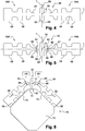
- FIGs 1a and 1b a classic wiper blade ( figure 1a ) and a flat windscreen wiper blade ( figure 1b ) according to the invention and designated by the general reference 8.
- the blade 8 comprises a wiper member 10.
- the member 10 is a blade wiper blade.
- the member 10 has a conventional shape extending in a main direction X.
- the member 10 comprises a heel 11 for attachment to the wiper blade, a hinge 12 and a lip 14 wiping a surface to be wiped.
- the lip 14 comprises a front end 16 wiping and first and second side faces 18, 20 wiping. The intersection of each first and second side faces 18, 20 with the end face 16 respectively defines a ridge 22, 24 for wiping.
- the member 10 comprises a material M based on elastomer (s), for example natural rubber having an outer surface 25.
- Each side face 18, 20 respectively comprises a lateral portion 26, 27 on which the material based on elastomer (s) has a surface thickness E having increased crosslinking.
- the end face 16 comprises two end portions 28, 29 on which the elastomer-based material (s) has a surface thickness E 'with increased crosslinking.
- E is substantially equal to E '.
- the intersection of each portion 26, 27 with each portion 28, 29 respectively defines each edge 22, 24 of wiping.
- the member 10 also comprises a coating 30 of at least a portion of the outer surface 25 of the lip 14.
- the coating 30 is intended to reduce the friction of the member 10 with the surface to be wiped.
- the member 10 is obtainable by this manufacturing method.
- the installation 34 comprises an extrusion device 36 of a binocular 38 made of elastomer-based material (s).
- the installation 34 also comprises two pre-cutting devices 40, 41 of the binoculars 38 and a device 43 for turning the binoculars 38.
- the installation 34 comprises devices 44, 45 for generating a beam of ions for ion bombardment on the binoculars 38.
- the installation 34 comprises two devices 46, 47 for positioning the binocular 38 with respect to each device 44, 45 respectively.
- the installation finally comprises a device 48 for cutting the binoculars 38.
- the installation also comprises means for moving and guiding (not shown) the extruded binoculars 38.
- the elastomer-based material (s) is extruded to obtain the binoculars 38 by means of the extrusion device 36.
- the binoculars 38 are made from the material of the invention. elastomer (s). After extrusion, the binocular 38 is vulcanized.
- binocular 38 comprising two bare and untreated members 48A, 48B for forming two treated and coated wipers 10.
- the members 48A, 48B are substantially identical and mechanically interconnected by a sacrificial connecting element 50 comprising a central leg 52.
- the binoculars 38 is substantially symmetrical with respect to two median transverse planes T and longitudinal L substantially parallel to the main direction X of each member 10.
- Each heel 11 and the central leg 52 respectively comprise bearing surfaces 58, 60 of the binoculars 38.
- the connecting element 50 is pre-cut on either side of the longitudinal plane L between each wiping member 48A, 48B that is bare and untreated, and the central leg 52 by means of pre-cutting device 40 comprising, for example, fixed pre-cutting blades, rotating blades or razor blades.
- the precision of the pre-cutting device 40 has an accuracy of 0.10 mm, or even less than 0.05 mm, which makes it possible to adjust the depth of the notches.
- the pre-cutting step is carried out continuously by moving the binocular 38 in contact with the blades of the devices 40, 41.
- the moving means of the binoculars 38 comprise drive rollers of the binoculars.
- the pre-cut-out binocular 62 shown in FIG. figure 5 thus comprises four notches 64, 66 that are symmetrical two by two with respect to the transverse median T and longitudinal L planes.
- the notches 64 are disposed on the side opposite the notches 66 with respect to the longitudinal median plane T.
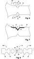
- Each notch 64 , 66 has an outer surface 68 to be treated by ion bombardment.
- This material bridge 67 is generally between 0.02 and 0.2 mm, preferably between 0.05 and 0.1 mm in order to guarantee easy separation of the members 10 while ensuring good cohesion of the pre-cut binoculars in the case. process
- each outer surface 68 includes one of the front portions 28, 29 and one of the side portions 26, 27 defining one of the wiping edges 22 , 24.
- This outer surface 68 has a general V shape.
- Each naked and untreated member 48A, 48B of the binocular 38 is movable relative to the other member 48A, 48B bare and untreated between an open position of the notch in which the outer surface 68 is exposed to the treatment by ion bombardment and a closing position of the notch in which the outer surface 68 of the notch is masked.
- each bare and untreated member 10 is moved relative to each other by means of the device. 46.
- the positioning device 46 is arranged so that the outer surface 68 of the notches 64 to be treated by ion bombardment is exposed to the ion beam generated by the device 44.
- the device 46 comprises a support 70 having a support surface 72 of the bearing surface 60 of the central leg and two support surfaces 74 of each bearing surface 58 of each heel 11.
- Each support surface 74 forms a predetermined angle with the surface 72. This angle is between 20 ° and 60 °, in this case the angle is substantially equal to 45 °.
- each outer surface 68 of each notch 66 defines an angle substantially equal to 45 °.
- a first step of treatment by ion bombardment is treated by ion bombardment the binocular 38 including the outer surface 68 of the notches 64 in the open position.
- the angle of incidence of the ion beam with respect to the external surface to be treated is between 0 and 45 °, here 20 °.
- the binocular 38 is moved continuously, by means of guiding and moving means, substantially parallel to the direction X with respect to the device 44 so as to expose the entirety of the external surface 68 of the devices. Notches 64.
- the displacement of the binocular 38 relative to the device 44 is performed in a vacuum chamber in which the pressure is substantially equal to 10 -3 mbar.
- the speed of movement is such that the treatment time per cm 2 of binoculars 38 is substantially equal to 2 seconds.
- the ion bombardment is carried out by micro-sources which may be based, for example, on a filament technology or on a technology type ECR (Electron Cylonic Resonance) with multi-energy ions of nitrogen.
- these micro-sources allow to design a device whose size is small.
- several ion beams can be used in series so as to obtain a treatment intensity adapted to the speed of movement of the binocular 38.
- the number of sources and the speed of displacement of the binoculars 38 can be implanted in the material between 10 14 and 10 16 ions / cm 2 .
- the extraction voltage is between 35kV and 100kV, here 50 kV.
- Part 29 of the outer surface 25 from which the material M extends has a surface thickness with increased crosslinking.
- the binocular 38 is turned over with respect to the longitudinal median plane T by means of the device 43 for reversing the binoculars 38.
- a second step of positioning the binocular 38 similar to the first positioning step the binocular 38 is positioned relative to the device 45 for generating an ion beam.
- each naked member is moved relative to each other by means of the displacement device 47 so that the outer surface 68 of the nicks 66 to be treated by ion bombardment is exposed to the ion beam generated. by the device 45.
- the binoculars 38 are treated by ion bombardment, in particular the external surfaces 68 of the notches 66 in the open position.
- Part 28 of the outer surface 25 from which the material M extends has a surface thickness with increased crosslinking.
- the coating 30 is deposited on the outer surface 25 of the member 10.
- each precursor 48A, 48B is separated from the sacrificial connecting element 50 by means of the device 48 which ruptures the material bridge 67.
- the sacrificial element 50 between the wiping members 48A, 48B is optional, it allows in particular better guidance of the binocular 38.
- there is no element 50 there is only one only pre-cut between each each wiper member 48A, 48B on either side of the longitudinal plane L. It is also possible to treat the entire lip, see the entire surface of the part and not only the parts in the vicinity of the cuts.
- Sample A corresponds to a wiper member manufactured by the process according to the invention described above but during which the coating step was omitted.
- Sample B corresponds to a body without a coating made during a process in which the notch is cut after ionically bombarding the binocular from which the organ is derived.
- Sample C corresponds to a wiper member 10 made by the process according to the invention described above.
- Sample D corresponds to an organ comprising a coating as described above and manufactured during a process in which the notch is cut after ionically bombarding the binocular from which the organ is derived.
- the binocular is ionically bombarded under a nitrogen atmosphere at an extraction voltage of 50 kV at a working pressure of 10 -3 bar and with an angle of incidence of 10 °.
- the acoustic performances of the samples are tested by means of a test making it possible to quantify the occurrences of vibration noise of each sample displaced in translation on a flat pane at speeds and by applying predetermined pressures simulating conditions of use under lubricated conditions. .
- the test is described in detail in the publication "Wiper rubber blade squeal noise test: a methodology for its characterization and influential factors study” by A. Sanon and presented at the "Automotive and Rail comfort, acoustics, vibrations & thermal issues” conference held in October 2010.
- the acoustic performances are tested on new samples (occurrence of the initial noise) and on worn samples (occurrence of the noise after 50,000 cycles).
- the wear of the samples is carried out by means of an alternating friction machine moving an ice square of 10 cm 2 over a course of 10 cm.
- the sample is positioned on the ice with a pressure of 15g.cm -1 and the speed is 45 roundtrips (one cycle) per minute.
- Table 1 Comparison of vibration noise occurrences obtained with different wipers.
- Table 1 shows that, when ionically bombarding the notch, the occurrence of the vibration noise decreases.
- Table 1 shows that the presence of a coating, in particular a graphite coating, also reduces the occurrence of vibration noise. .
- a coating improves the sound comfort of the occupant of the vehicle regardless of the wear of the body.
- Table 1 shows that the combination of the order of the pre-slit and ion bombardment steps and the use of the coating has a synergistic effect of reducing the occurrence of vibration noise. This synergistic effect is particularly present when the member has advanced wear. Indeed, without coating, the reduction of the vibration noise with respect to the sample B is of the order of 25-30% for the sample A manufactured with a process during which the notch is ionically bombarded. With a coating, the reduction of the vibration noise with respect to the sample D is of the order of 50% for the sample C manufactured with a process during which the notch is ionically bombarded.
- Samples A to D are worn using the alternative friction machine described in Example 1. Wear is monitored hourly. The number of cycles necessary to obtain a used volume of 0.5 mm 3 is determined . This volume corresponds to significant wear beyond which the wiping performance is degraded. Table 2: Comparison of wear resistances (number of cycles to achieve 0.5mm3 of wear) obtained with different wipers.
- Table 1 shows that when ionically bombarding the notch, the wear resistance increases.
- Table 1 shows that the presence of a coating, in particular a graphite coating, improves the wear resistance.
- a coating improves the strength of the organ.
- Table 1 shows that the combination of the order of the pre-slit and ion bombardment steps and the use of the coating has a synergistic effect of increasing the wear resistance.
- the increase of the wear resistance with respect to the sample B is of the order of 30% for the sample A manufactured with a method during which the notch is ionically bombarded.
- the increase of the wear resistance with respect to the sample D is of the order of 50% for the sample C manufactured with a process during which the notch is ionically bombarded.
- Table 2 Comparison of wear resistances (number of cycles to achieve 0.5mm3 of wear) obtained with different wipers.
- Table 1 shows that when ionically bombarding the notch, the wear resistance increases.
- Table 1 shows that the presence of a coating, in particular a graphite coating, improves the wear resistance.
- a coating improves the strength of the organ.
- Table 1 shows that the combination of the order of the pre-slit and ion bombardment steps and the use of the coating has a synergistic effect of increasing the wear resistance.
- the increase of the wear resistance with respect to the sample B is of the order of 30% for the sample A manufactured with a method during which the notch is ionically bombarded.
- the increase of the wear resistance with respect to the sample D is of the order of 50% for the sample C manufactured with a process during which the notch is ionically bombarded.
Landscapes
- Chemical & Material Sciences (AREA)
- Organic Chemistry (AREA)
- Health & Medical Sciences (AREA)
- Chemical Kinetics & Catalysis (AREA)
- Medicinal Chemistry (AREA)
- Polymers & Plastics (AREA)
- General Chemical & Material Sciences (AREA)
- Engineering & Computer Science (AREA)
- Mechanical Engineering (AREA)
- Treatments Of Macromolecular Shaped Articles (AREA)
- Laminated Bodies (AREA)
- Lining Or Joining Of Plastics Or The Like (AREA)
- Manufacture Of Macromolecular Shaped Articles (AREA)
Claims (9)
- Verfahren zur Herstellung eines Wischerelements (10) aus einem Material auf Basis von Elastomer(en) aus einem Paar (38) von miteinander verbundenen Wischerelementen (10), wobei das Paar (38) durch vier zwei und zwei zu den Quer-(T) und Längsmittelebenen (L) symmetrische Kerben (64, 66) vorgespalten sind, wobei erste Kerben (64) auf der gegenüberliegenden Seite von zweiten Kerben (66) in Bezug zur Längsmittelebene (T) angeordnet und durch eine Restmaterialbrücke (67) getrennt sind, die eine spätere Trennung der Elemente (10) voneinander ermöglichen soll, wobei bei dem Verfahren mindestens ein Teil (28, 29) einer Außenfläche (68) der Kerbe (64, 66) durch Ionenbeschuss behandelt wird, wobei der Ionenbeschuss mit einer Extraktionsspannung zwischen 35 und 100 kV durchgeführt wird, damit der mindestens eine Teil (28, 29) eine höhere Vernetzung auf einer Oberflächendicke (E') von weniger als 5 µm ausgehend von der Außenfläche aufweist, wobei die Elemente des Paars (38) zueinander zwischen einer Öffnungsposition der Kerbe (64, 66), in der der Teil der Außenfläche (68) der Behandlung durch Ionenbeschuss ausgesetzt ist, und einer Verschlussposition der Kerbe (64, 66), in der der Teil der Außenfläche (68) verdeckt ist, beweglich sind, wobei der Teil der Außenfläche (68) der Kerbe (64, 66) in der Öffnungsposition durch Ionenbeschuss behandelt wird.
- Verfahren nach Anspruch 1, bei dem der Ionenbeschuss mit Hilfe von Ionenstrahlen durchgeführt wird, die von Gasen wie Helium, Neon, Krypton, Argon, Xenon, Disauerstoff oder Distickstoff allein oder im Gemisch stammen.
- Verfahren nach Anspruch 1 oder 2, bei dem eine Verkleidung (30) aufgebracht wird, die die Reibung auf einer Außenfläche (25) des Paars (38) von Elementen (10) nach dem Behandlungsschritt mit Ionenbeschuss verringern soll.
- Verfahren nach einem der vorhergehenden Ansprüche, umfassend nach dem Schritt des Ionenbeschusses und des Aufbringens der Verkleidung (30) einen Schritt der Trennung des Paars (38).
- Verfahren nach einem der vorhergehenden Ansprüche, bei dem zwischen 1014 und 1016 Ionen/cm2 in das Material implantiert werden.
- Paar (38) von Wischerelementen aus einem Material auf Basis von Elastomer(en), dadurch gekennzeichnet, dass es vier zwei und zwei zu den Quer-(T) und Längsmittelebenen (L) symmetrische Kerben (64, 66) umfasst, wobei erste Kerben (64) auf der gegenüberliegenden Seite von zweiten Kerben (66) in Bezug zur Längsmittelebene (T) angeordnet und durch eine Restmaterialbrücke (67) getrennt sind, und wobei die Kerben mindestens einen Teil (28, 29) einer Außenfläche (68) aufweisen, von dem aus sich das Material auf Basis von Elastomer(en) erstreckt, wobei die Außenfläche eine höhere Vernetzung auf einer Oberflächendicke (E') von weniger als 5 µm ausgehend von der Außenfläche aufweist.
- Wischerelement (10), umfassend ein Material auf Basis von Elastomer(en), das geeignet ist, durch das Verfahren nach einem der Ansprüche 1 bis 5 erhalten zu werden.
- Wischervorrichtung (8), umfassend ein Wischerelement (10) nach dem vorhergehenden Anspruch.
- Verwendung eines Verfahrens nach einem der Ansprüche 1 bis 5, um die Häre und die Abriebfestigkeit der Verkleidung (30) und/oder des Materials eines Wischerelements (10), wie in Anspruch 7 definiert, zu erhöhen, wobei diese Erhöhung bewirkt, dass das Geräusch, das das Element (10) beim Reiben auf der zu wischenden Fläche erzeugen kann, verringert wird, wobei es das Element (10) somit ermöglicht, den Geräuschkomfort für den Insassen des Fahrzeugs zu verbessern.
Applications Claiming Priority (2)
| Application Number | Priority Date | Filing Date | Title |
|---|---|---|---|
| FR1004904A FR2969079B1 (fr) | 2010-12-15 | 2010-12-15 | Procede de fabrication d'une jumelle d'organes d'essuyage |
| PCT/EP2011/072743 WO2012080322A1 (fr) | 2010-12-15 | 2011-12-14 | Procédé de fabrication d'une jumelle d'organes d'essuyage |
Publications (2)
| Publication Number | Publication Date |
|---|---|
| EP2652017A1 EP2652017A1 (de) | 2013-10-23 |
| EP2652017B1 true EP2652017B1 (de) | 2018-11-07 |
Family
ID=44343968
Family Applications (1)
| Application Number | Title | Priority Date | Filing Date |
|---|---|---|---|
| EP11794765.5A Active EP2652017B1 (de) | 2010-12-15 | 2011-12-14 | Verfahren zur herstellung eines wischerelementpaars |
Country Status (5)
| Country | Link |
|---|---|
| EP (1) | EP2652017B1 (de) |
| CN (1) | CN103380169B (de) |
| FR (1) | FR2969079B1 (de) |
| MX (1) | MX2013006879A (de) |
| WO (1) | WO2012080322A1 (de) |
Families Citing this family (2)
| Publication number | Priority date | Publication date | Assignee | Title |
|---|---|---|---|---|
| FR2969078B1 (fr) | 2010-12-15 | 2013-04-12 | Valeo Systemes Dessuyage | Organe d'essuyage en materiau a base d'elastomere(s) sur-reticule |
| DE102012209953A1 (de) * | 2012-06-14 | 2013-12-19 | Robert Bosch Gmbh | Verfahren zum Herstellen einer Wischleiste und eine Wischleiste |
Family Cites Families (6)
| Publication number | Priority date | Publication date | Assignee | Title |
|---|---|---|---|---|
| JPS6393650A (ja) * | 1986-10-09 | 1988-04-23 | Nippon Waipabureede Kk | ワイパブレ−ド用ゴム |
| FR2749852B1 (fr) | 1996-06-13 | 2004-01-23 | Valeo Systemes Dessuyage | Solution pour realiser un revetement sur un profile, lame d'essuyage revetue d'une telle solution, procede pour revetir un profile d'un tel revetement et lame d'essuyage revetue d'un revetement, obtenue par un tel procede |
| DE19814805A1 (de) * | 1998-04-02 | 1999-10-07 | Bosch Gmbh Robert | Beschichtungsverfahren eines Wischergummis |
| DE10025689A1 (de) * | 2000-05-24 | 2001-12-06 | Bosch Gmbh Robert | Verfahren und Vorrichtung zum Beschichten von mindestens einem Wischgummi |
| KR100500040B1 (ko) | 2003-05-09 | 2005-07-18 | 주식회사 케이핍 | 전자파 차단, 대전방지, 표면경화를 위한 고분자재료성형품의 표면 이온화 방법 |
| FR2899242B1 (fr) | 2007-04-05 | 2010-10-22 | Quertech Ingenierie | Procede de durcissement par implantation d'ions d'helium dans une piece metallique |
-
2010
- 2010-12-15 FR FR1004904A patent/FR2969079B1/fr active Active
-
2011
- 2011-12-14 EP EP11794765.5A patent/EP2652017B1/de active Active
- 2011-12-14 WO PCT/EP2011/072743 patent/WO2012080322A1/fr not_active Ceased
- 2011-12-14 CN CN201180067646.6A patent/CN103380169B/zh active Active
- 2011-12-14 MX MX2013006879A patent/MX2013006879A/es unknown
Non-Patent Citations (1)
| Title |
|---|
| None * |
Also Published As
| Publication number | Publication date |
|---|---|
| CN103380169B (zh) | 2015-08-26 |
| EP2652017A1 (de) | 2013-10-23 |
| FR2969079A1 (fr) | 2012-06-22 |
| FR2969079B1 (fr) | 2013-04-12 |
| MX2013006879A (es) | 2013-07-05 |
| CN103380169A (zh) | 2013-10-30 |
| WO2012080322A1 (fr) | 2012-06-21 |
Similar Documents
| Publication | Publication Date | Title |
|---|---|---|
| EP2652019B1 (de) | Behandlungsverfahren für scheibenwischerblatt | |
| EP2403899B1 (de) | Verfahren zur behandlung einer oberfläche eines elastomerteils mit multienergetischen ionen he+ und he2+ | |
| EP2652017B1 (de) | Verfahren zur herstellung eines wischerelementpaars | |
| EP2652018B1 (de) | Wischelement aus einem material auf der basis von übervernetzten elastomer(en) | |
| FR2555698A1 (fr) | Garniture de glissement et d'etancheite | |
| FR2977258A1 (fr) | Composition de renovation d'un organe d'essuyage | |
| FR2988354A1 (fr) | Procede de realisation d'une lame d'essuyage avec un fluide surcritique | |
| WO2024200825A1 (fr) | Composition de revêtement pour lame d'essuyage de balai d'essuie-glace | |
| FR2969080A1 (fr) | Procede de traitement de balai essuie glace | |
| FR2966533A1 (fr) | Organe de frottement pour l'assemblage de deux pieces. | |
| EP3078554B1 (de) | Scheibenwischerblatt für scheibenwischerarm | |
| FR2976536A1 (fr) | Procede de traitement d'un organe d'essuyage | |
| EP3336448B1 (de) | Klemmvorrichtung für ein fotovoltaikmodul mit vier klemmbacken | |
| EP1783403B1 (de) | Dichtungsprofil zur Sicherung einer wasserdichten Übergangsfläche zwischen zwei beweglichen Strukturen, dessen Herstellungsverfahren und ein Dichtungsmodul mit diesem Profil | |
| WO2024213611A1 (fr) | Composition de revêtement pour lame d'essuyage de balai d'essuie-glace | |
| FR3143619A1 (fr) | Composition de revêtement pour lame d'essuyage de balai d'essuie-glace | |
| FR3124775A1 (fr) | Lame d’essuyage comportant un corps de base et un corps lubrifiant réticulés | |
| EP2709823A1 (de) | Abdichtungsvorrichtung zur vakuumbehandlung einer objektoberfläche | |
| JP2016215848A (ja) | ブレードラバー | |
| FR2914725A3 (fr) | Joint de boitier de troisieme feu stop | |
| FR2749013A1 (fr) | Piece moulee en materiau traite a l'iode et procede de fabrication de ce materiau |
Legal Events
| Date | Code | Title | Description |
|---|---|---|---|
| PUAI | Public reference made under article 153(3) epc to a published international application that has entered the european phase |
Free format text: ORIGINAL CODE: 0009012 |
|
| 17P | Request for examination filed |
Effective date: 20130531 |
|
| AK | Designated contracting states |
Kind code of ref document: A1 Designated state(s): AL AT BE BG CH CY CZ DE DK EE ES FI FR GB GR HR HU IE IS IT LI LT LU LV MC MK MT NL NO PL PT RO RS SE SI SK SM TR |
|
| DAX | Request for extension of the european patent (deleted) | ||
| 17Q | First examination report despatched |
Effective date: 20170307 |
|
| GRAP | Despatch of communication of intention to grant a patent |
Free format text: ORIGINAL CODE: EPIDOSNIGR1 |
|
| INTG | Intention to grant announced |
Effective date: 20180605 |
|
| GRAS | Grant fee paid |
Free format text: ORIGINAL CODE: EPIDOSNIGR3 |
|
| GRAA | (expected) grant |
Free format text: ORIGINAL CODE: 0009210 |
|
| AK | Designated contracting states |
Kind code of ref document: B1 Designated state(s): AL AT BE BG CH CY CZ DE DK EE ES FI FR GB GR HR HU IE IS IT LI LT LU LV MC MK MT NL NO PL PT RO RS SE SI SK SM TR |
|
| REG | Reference to a national code |
Ref country code: GB Ref legal event code: FG4D Free format text: NOT ENGLISH |
|
| REG | Reference to a national code |
Ref country code: CH Ref legal event code: EP Ref country code: AT Ref legal event code: REF Ref document number: 1062008 Country of ref document: AT Kind code of ref document: T Effective date: 20181115 |
|
| REG | Reference to a national code |
Ref country code: IE Ref legal event code: FG4D Free format text: LANGUAGE OF EP DOCUMENT: FRENCH |
|
| REG | Reference to a national code |
Ref country code: DE Ref legal event code: R096 Ref document number: 602011053678 Country of ref document: DE |
|
| REG | Reference to a national code |
Ref country code: NL Ref legal event code: MP Effective date: 20181107 |
|
| REG | Reference to a national code |
Ref country code: LT Ref legal event code: MG4D |
|
| REG | Reference to a national code |
Ref country code: AT Ref legal event code: MK05 Ref document number: 1062008 Country of ref document: AT Kind code of ref document: T Effective date: 20181107 |
|
| PG25 | Lapsed in a contracting state [announced via postgrant information from national office to epo] |
Ref country code: IS Free format text: LAPSE BECAUSE OF FAILURE TO SUBMIT A TRANSLATION OF THE DESCRIPTION OR TO PAY THE FEE WITHIN THE PRESCRIBED TIME-LIMIT Effective date: 20190307 Ref country code: ES Free format text: LAPSE BECAUSE OF FAILURE TO SUBMIT A TRANSLATION OF THE DESCRIPTION OR TO PAY THE FEE WITHIN THE PRESCRIBED TIME-LIMIT Effective date: 20181107 Ref country code: NO Free format text: LAPSE BECAUSE OF FAILURE TO SUBMIT A TRANSLATION OF THE DESCRIPTION OR TO PAY THE FEE WITHIN THE PRESCRIBED TIME-LIMIT Effective date: 20190207 Ref country code: LT Free format text: LAPSE BECAUSE OF FAILURE TO SUBMIT A TRANSLATION OF THE DESCRIPTION OR TO PAY THE FEE WITHIN THE PRESCRIBED TIME-LIMIT Effective date: 20181107 Ref country code: BG Free format text: LAPSE BECAUSE OF FAILURE TO SUBMIT A TRANSLATION OF THE DESCRIPTION OR TO PAY THE FEE WITHIN THE PRESCRIBED TIME-LIMIT Effective date: 20190207 Ref country code: HR Free format text: LAPSE BECAUSE OF FAILURE TO SUBMIT A TRANSLATION OF THE DESCRIPTION OR TO PAY THE FEE WITHIN THE PRESCRIBED TIME-LIMIT Effective date: 20181107 Ref country code: AT Free format text: LAPSE BECAUSE OF FAILURE TO SUBMIT A TRANSLATION OF THE DESCRIPTION OR TO PAY THE FEE WITHIN THE PRESCRIBED TIME-LIMIT Effective date: 20181107 Ref country code: LV Free format text: LAPSE BECAUSE OF FAILURE TO SUBMIT A TRANSLATION OF THE DESCRIPTION OR TO PAY THE FEE WITHIN THE PRESCRIBED TIME-LIMIT Effective date: 20181107 Ref country code: FI Free format text: LAPSE BECAUSE OF FAILURE TO SUBMIT A TRANSLATION OF THE DESCRIPTION OR TO PAY THE FEE WITHIN THE PRESCRIBED TIME-LIMIT Effective date: 20181107 |
|
| PG25 | Lapsed in a contracting state [announced via postgrant information from national office to epo] |
Ref country code: SE Free format text: LAPSE BECAUSE OF FAILURE TO SUBMIT A TRANSLATION OF THE DESCRIPTION OR TO PAY THE FEE WITHIN THE PRESCRIBED TIME-LIMIT Effective date: 20181107 Ref country code: RS Free format text: LAPSE BECAUSE OF FAILURE TO SUBMIT A TRANSLATION OF THE DESCRIPTION OR TO PAY THE FEE WITHIN THE PRESCRIBED TIME-LIMIT Effective date: 20181107 Ref country code: AL Free format text: LAPSE BECAUSE OF FAILURE TO SUBMIT A TRANSLATION OF THE DESCRIPTION OR TO PAY THE FEE WITHIN THE PRESCRIBED TIME-LIMIT Effective date: 20181107 Ref country code: PT Free format text: LAPSE BECAUSE OF FAILURE TO SUBMIT A TRANSLATION OF THE DESCRIPTION OR TO PAY THE FEE WITHIN THE PRESCRIBED TIME-LIMIT Effective date: 20190307 Ref country code: GR Free format text: LAPSE BECAUSE OF FAILURE TO SUBMIT A TRANSLATION OF THE DESCRIPTION OR TO PAY THE FEE WITHIN THE PRESCRIBED TIME-LIMIT Effective date: 20190208 Ref country code: NL Free format text: LAPSE BECAUSE OF FAILURE TO SUBMIT A TRANSLATION OF THE DESCRIPTION OR TO PAY THE FEE WITHIN THE PRESCRIBED TIME-LIMIT Effective date: 20181107 |
|
| REG | Reference to a national code |
Ref country code: DE Ref legal event code: R119 Ref document number: 602011053678 Country of ref document: DE |
|
| PG25 | Lapsed in a contracting state [announced via postgrant information from national office to epo] |
Ref country code: IT Free format text: LAPSE BECAUSE OF FAILURE TO SUBMIT A TRANSLATION OF THE DESCRIPTION OR TO PAY THE FEE WITHIN THE PRESCRIBED TIME-LIMIT Effective date: 20181107 Ref country code: DK Free format text: LAPSE BECAUSE OF FAILURE TO SUBMIT A TRANSLATION OF THE DESCRIPTION OR TO PAY THE FEE WITHIN THE PRESCRIBED TIME-LIMIT Effective date: 20181107 Ref country code: PL Free format text: LAPSE BECAUSE OF FAILURE TO SUBMIT A TRANSLATION OF THE DESCRIPTION OR TO PAY THE FEE WITHIN THE PRESCRIBED TIME-LIMIT Effective date: 20181107 Ref country code: CZ Free format text: LAPSE BECAUSE OF FAILURE TO SUBMIT A TRANSLATION OF THE DESCRIPTION OR TO PAY THE FEE WITHIN THE PRESCRIBED TIME-LIMIT Effective date: 20181107 |
|
| REG | Reference to a national code |
Ref country code: CH Ref legal event code: PL |
|
| PG25 | Lapsed in a contracting state [announced via postgrant information from national office to epo] |
Ref country code: SM Free format text: LAPSE BECAUSE OF FAILURE TO SUBMIT A TRANSLATION OF THE DESCRIPTION OR TO PAY THE FEE WITHIN THE PRESCRIBED TIME-LIMIT Effective date: 20181107 Ref country code: SK Free format text: LAPSE BECAUSE OF FAILURE TO SUBMIT A TRANSLATION OF THE DESCRIPTION OR TO PAY THE FEE WITHIN THE PRESCRIBED TIME-LIMIT Effective date: 20181107 Ref country code: EE Free format text: LAPSE BECAUSE OF FAILURE TO SUBMIT A TRANSLATION OF THE DESCRIPTION OR TO PAY THE FEE WITHIN THE PRESCRIBED TIME-LIMIT Effective date: 20181107 Ref country code: LU Free format text: LAPSE BECAUSE OF NON-PAYMENT OF DUE FEES Effective date: 20181214 Ref country code: RO Free format text: LAPSE BECAUSE OF FAILURE TO SUBMIT A TRANSLATION OF THE DESCRIPTION OR TO PAY THE FEE WITHIN THE PRESCRIBED TIME-LIMIT Effective date: 20181107 Ref country code: MC Free format text: LAPSE BECAUSE OF FAILURE TO SUBMIT A TRANSLATION OF THE DESCRIPTION OR TO PAY THE FEE WITHIN THE PRESCRIBED TIME-LIMIT Effective date: 20181107 |
|
| PLBE | No opposition filed within time limit |
Free format text: ORIGINAL CODE: 0009261 |
|
| STAA | Information on the status of an ep patent application or granted ep patent |
Free format text: STATUS: NO OPPOSITION FILED WITHIN TIME LIMIT |
|
| REG | Reference to a national code |
Ref country code: IE Ref legal event code: MM4A |
|
| REG | Reference to a national code |
Ref country code: BE Ref legal event code: MM Effective date: 20181231 |
|
| 26N | No opposition filed |
Effective date: 20190808 |
|
| GBPC | Gb: european patent ceased through non-payment of renewal fee |
Effective date: 20190207 |
|
| PG25 | Lapsed in a contracting state [announced via postgrant information from national office to epo] |
Ref country code: SI Free format text: LAPSE BECAUSE OF FAILURE TO SUBMIT A TRANSLATION OF THE DESCRIPTION OR TO PAY THE FEE WITHIN THE PRESCRIBED TIME-LIMIT Effective date: 20181107 Ref country code: DE Free format text: LAPSE BECAUSE OF NON-PAYMENT OF DUE FEES Effective date: 20190702 Ref country code: IE Free format text: LAPSE BECAUSE OF NON-PAYMENT OF DUE FEES Effective date: 20181214 |
|
| PG25 | Lapsed in a contracting state [announced via postgrant information from national office to epo] |
Ref country code: BE Free format text: LAPSE BECAUSE OF NON-PAYMENT OF DUE FEES Effective date: 20181231 |
|
| PG25 | Lapsed in a contracting state [announced via postgrant information from national office to epo] |
Ref country code: LI Free format text: LAPSE BECAUSE OF NON-PAYMENT OF DUE FEES Effective date: 20181231 Ref country code: CH Free format text: LAPSE BECAUSE OF NON-PAYMENT OF DUE FEES Effective date: 20181231 |
|
| PG25 | Lapsed in a contracting state [announced via postgrant information from national office to epo] |
Ref country code: MT Free format text: LAPSE BECAUSE OF FAILURE TO SUBMIT A TRANSLATION OF THE DESCRIPTION OR TO PAY THE FEE WITHIN THE PRESCRIBED TIME-LIMIT Effective date: 20181107 Ref country code: GB Free format text: LAPSE BECAUSE OF NON-PAYMENT OF DUE FEES Effective date: 20190207 |
|
| PG25 | Lapsed in a contracting state [announced via postgrant information from national office to epo] |
Ref country code: TR Free format text: LAPSE BECAUSE OF FAILURE TO SUBMIT A TRANSLATION OF THE DESCRIPTION OR TO PAY THE FEE WITHIN THE PRESCRIBED TIME-LIMIT Effective date: 20181107 |
|
| PG25 | Lapsed in a contracting state [announced via postgrant information from national office to epo] |
Ref country code: HU Free format text: LAPSE BECAUSE OF FAILURE TO SUBMIT A TRANSLATION OF THE DESCRIPTION OR TO PAY THE FEE WITHIN THE PRESCRIBED TIME-LIMIT; INVALID AB INITIO Effective date: 20111214 Ref country code: CY Free format text: LAPSE BECAUSE OF FAILURE TO SUBMIT A TRANSLATION OF THE DESCRIPTION OR TO PAY THE FEE WITHIN THE PRESCRIBED TIME-LIMIT Effective date: 20181107 Ref country code: MK Free format text: LAPSE BECAUSE OF NON-PAYMENT OF DUE FEES Effective date: 20181107 |
|
| P01 | Opt-out of the competence of the unified patent court (upc) registered |
Effective date: 20230528 |
|
| PGFP | Annual fee paid to national office [announced via postgrant information from national office to epo] |
Ref country code: FR Payment date: 20251230 Year of fee payment: 15 |