EP2650549A2 - Agencement électro-hydraulique, procédé de commande de l'agencement électro-hydraulique et machine de travail mobile dotée de l'arrangement électro-hydraulique - Google Patents
Agencement électro-hydraulique, procédé de commande de l'agencement électro-hydraulique et machine de travail mobile dotée de l'arrangement électro-hydraulique Download PDFInfo
- Publication number
- EP2650549A2 EP2650549A2 EP20130158868 EP13158868A EP2650549A2 EP 2650549 A2 EP2650549 A2 EP 2650549A2 EP 20130158868 EP20130158868 EP 20130158868 EP 13158868 A EP13158868 A EP 13158868A EP 2650549 A2 EP2650549 A2 EP 2650549A2
- Authority
- EP
- European Patent Office
- Prior art keywords
- valves
- valve
- valve group
- free flow
- effective free
- Prior art date
- Legal status (The legal status is an assumption and is not a legal conclusion. Google has not performed a legal analysis and makes no representation as to the accuracy of the status listed.)
- Withdrawn
Links
Images

Classifications
-
- B—PERFORMING OPERATIONS; TRANSPORTING
- B62—LAND VEHICLES FOR TRAVELLING OTHERWISE THAN ON RAILS
- B62D—MOTOR VEHICLES; TRAILERS
- B62D5/00—Power-assisted or power-driven steering
- B62D5/06—Power-assisted or power-driven steering fluid, i.e. using a pressurised fluid for most or all the force required for steering a vehicle
- B62D5/09—Power-assisted or power-driven steering fluid, i.e. using a pressurised fluid for most or all the force required for steering a vehicle characterised by means for actuating valves
- B62D5/091—Hydraulic steer-by-wire systems, e.g. the valve being actuated by an electric motor
-
- F—MECHANICAL ENGINEERING; LIGHTING; HEATING; WEAPONS; BLASTING
- F15—FLUID-PRESSURE ACTUATORS; HYDRAULICS OR PNEUMATICS IN GENERAL
- F15B—SYSTEMS ACTING BY MEANS OF FLUIDS IN GENERAL; FLUID-PRESSURE ACTUATORS, e.g. SERVOMOTORS; DETAILS OF FLUID-PRESSURE SYSTEMS, NOT OTHERWISE PROVIDED FOR
- F15B19/00—Testing; Calibrating; Fault detection or monitoring; Simulation or modelling of fluid-pressure systems or apparatus not otherwise provided for
- F15B19/005—Fault detection or monitoring
-
- F—MECHANICAL ENGINEERING; LIGHTING; HEATING; WEAPONS; BLASTING
- F15—FLUID-PRESSURE ACTUATORS; HYDRAULICS OR PNEUMATICS IN GENERAL
- F15B—SYSTEMS ACTING BY MEANS OF FLUIDS IN GENERAL; FLUID-PRESSURE ACTUATORS, e.g. SERVOMOTORS; DETAILS OF FLUID-PRESSURE SYSTEMS, NOT OTHERWISE PROVIDED FOR
- F15B2211/00—Circuits for servomotor systems
- F15B2211/30—Directional control
- F15B2211/305—Directional control characterised by the type of valves
- F15B2211/3056—Assemblies of multiple valves
- F15B2211/30565—Assemblies of multiple valves having multiple valves for a single output member, e.g. for creating higher valve function by use of multiple valves like two 2/2-valves replacing a 5/3-valve
- F15B2211/30575—Assemblies of multiple valves having multiple valves for a single output member, e.g. for creating higher valve function by use of multiple valves like two 2/2-valves replacing a 5/3-valve in a Wheatstone Bridge arrangement (also half bridges)
-
- F—MECHANICAL ENGINEERING; LIGHTING; HEATING; WEAPONS; BLASTING
- F15—FLUID-PRESSURE ACTUATORS; HYDRAULICS OR PNEUMATICS IN GENERAL
- F15B—SYSTEMS ACTING BY MEANS OF FLUIDS IN GENERAL; FLUID-PRESSURE ACTUATORS, e.g. SERVOMOTORS; DETAILS OF FLUID-PRESSURE SYSTEMS, NOT OTHERWISE PROVIDED FOR
- F15B2211/00—Circuits for servomotor systems
- F15B2211/30—Directional control
- F15B2211/32—Directional control characterised by the type of actuation
- F15B2211/327—Directional control characterised by the type of actuation electrically or electronically
- F15B2211/328—Directional control characterised by the type of actuation electrically or electronically with signal modulation, e.g. pulse width modulation [PWM]
-
- F—MECHANICAL ENGINEERING; LIGHTING; HEATING; WEAPONS; BLASTING
- F15—FLUID-PRESSURE ACTUATORS; HYDRAULICS OR PNEUMATICS IN GENERAL
- F15B—SYSTEMS ACTING BY MEANS OF FLUIDS IN GENERAL; FLUID-PRESSURE ACTUATORS, e.g. SERVOMOTORS; DETAILS OF FLUID-PRESSURE SYSTEMS, NOT OTHERWISE PROVIDED FOR
- F15B2211/00—Circuits for servomotor systems
- F15B2211/60—Circuit components or control therefor
- F15B2211/63—Electronic controllers
- F15B2211/6303—Electronic controllers using input signals
- F15B2211/6336—Electronic controllers using input signals representing a state of the output member, e.g. position, speed or acceleration
-
- F—MECHANICAL ENGINEERING; LIGHTING; HEATING; WEAPONS; BLASTING
- F15—FLUID-PRESSURE ACTUATORS; HYDRAULICS OR PNEUMATICS IN GENERAL
- F15B—SYSTEMS ACTING BY MEANS OF FLUIDS IN GENERAL; FLUID-PRESSURE ACTUATORS, e.g. SERVOMOTORS; DETAILS OF FLUID-PRESSURE SYSTEMS, NOT OTHERWISE PROVIDED FOR
- F15B2211/00—Circuits for servomotor systems
- F15B2211/60—Circuit components or control therefor
- F15B2211/665—Methods of control using electronic components
-
- F—MECHANICAL ENGINEERING; LIGHTING; HEATING; WEAPONS; BLASTING
- F15—FLUID-PRESSURE ACTUATORS; HYDRAULICS OR PNEUMATICS IN GENERAL
- F15B—SYSTEMS ACTING BY MEANS OF FLUIDS IN GENERAL; FLUID-PRESSURE ACTUATORS, e.g. SERVOMOTORS; DETAILS OF FLUID-PRESSURE SYSTEMS, NOT OTHERWISE PROVIDED FOR
- F15B2211/00—Circuits for servomotor systems
- F15B2211/80—Other types of control related to particular problems or conditions
- F15B2211/86—Control during or prevention of abnormal conditions
- F15B2211/863—Control during or prevention of abnormal conditions the abnormal condition being a hydraulic or pneumatic failure
- F15B2211/8636—Circuit failure, e.g. valve or hose failure
Definitions
- the invention relates to an electro-hydraulic arrangement according to the preamble of claim 1, a method for controlling such an electro-hydraulic arrangement and a mobile machine with such an electro-hydraulic arrangement.
- EP 2 388 178 A2 is disclosed an electro-hydraulic arrangement in the form of an electro-hydraulic steering.
- This has a trained as a synchronous cylinder steering cylinder with a piston which separates two cylinder chambers from each other.
- a respective cylinder chamber is connected to a supply line in each of which a first and a second valve is arranged fluidly parallel.
- a pressure medium supply of the cylinder chambers is controllable, whereby each cylinder chamber can be supplied with pressure medium.
- each cylinder chamber is connected to a return line, wherein in a respective return line, two valves are also arranged fluidly in parallel through which a connection to a tank up and is zuu Kunststoffbar. If a valve fails, for example by a valve spool of a valve jamming in an unactuated position, its function is simply taken over by the fluidically arranged parallel valve.
- WO 2007/028863 A1 Another electrohydraulic arrangement is disclosed.
- This has a hydraulic cylinder in the form of a differential cylinder with a one-sided piston rod, wherein a piston connected to the piston rod separates two cylinder chambers from each other.
- a connection of a respective cylinder chamber is connected via a respective supply line with a pressure medium source.
- switching valves are arranged fluidically in parallel in a respective supply line.
- the connection of a respective cylinder chamber is connected via a return line to a tank.
- switching valves are also arranged fluidly parallel.
- Valve slide valves of the supply and Return lines are acted upon by a spring in the direction of a closed position with a spring force and can be brought via an electric actuator in an open position.
- a self-test of the assembly is made which is not active during normal operation of the assembly. If a valve fails, this is detected by the system in the self-test due to pressure changes by tapping a pressure at several points of the electrohydraulic assembly and comparing it with previously calculated quantities. After fault detection, the failed valve is compensated by a new control of the other valves.
- the invention has for its object to provide an electro-hydraulic arrangement which is simple in terms of device design and has a high level of security. Furthermore, the invention has for its object to provide a method for controlling the electro-hydraulic arrangement, which leads to the safe use of an electro-hydraulic arrangement and can be executed with little effort. Further, the invention has for its object to provide a mobile machine with the electro-hydraulic arrangement, which is safe to use with low device complexity.
- a pressure medium supply which may be, for example, a hydraulic pump.
- a first supply line is a first connection of an actuator for adjusting the actuator in a first direction connectable to the pressure medium supply.
- a second connection of the actuator for adjusting the actuator in a second direction can be connected via a second supply line to the pressure medium supply.
- the first connection can be connected via a first return line and the second connection can be connected via a second return line to a pressure medium sink, in particular to a tank.
- a valve group is provided with a plurality of fluidically arranged in parallel valves for controlling a pressure medium volume flow.
- a valve group in this case preferably has two valves each.
- Via a sensor a position actual value of the actuator is detected.
- the position actual value is, for example, an adjustment position of the actuator.
- a control device With a control device, a control difference is formed from the actual position value and a predetermined position setpoint. Depending on the control difference, the control device controls an effective free flow cross-section of the valves. For example, the control device can simply regulate the valves as a P regulator.
- valves are automatically controlled by the control device according to the control difference and a safe adjustment of the actuator is achieved with low device technology and low control engineering effort.
- this automatic compensation of valve errors leads to a deterioration of the control quality and the maximum adjustment speed compared to the error-free system.
- the residual control quality is sufficient to continue to drive the hydraulic consumer or the actuator transitionally until a safe state has been reached.
- the effective free flow cross-section of the valves of a respective valve group is preferably changed as a function of the size of the control difference.
- the dependence is such that the greater the control difference, the more greater is then the effective free flow cross section of the controlled by the control device valves.
- the dependency can be simply linear.
- valves of a valve group can be controlled in terms of their effective free flow cross-section equal or in a fixed ratio to each other. As a result, the control effort for the control device is extremely low.
- the valves of a valve group are thus controlled in such a way that they have the same effective free flow cross section or a fixed relationship to one another with regard to their effective free flow cross section.
- the actuator is a steering cylinder, in particular a synchronous cylinder, which has a piston separating two control chambers from one another, the control chambers being connected to a respective connection. Since there are high safety requirements in terms of steerability in case of failure for a steering cylinder, which can be used in particular for mobile machines, they can be met with low device complexity by the electro-hydraulic arrangement according to the invention. A failure of a valve in the form that the valve spool of a valve remains in its closed position, resulting in the worst case that a maximum steering speed of the steering cylinder is no longer achieved. However, the maximum steering speed is needed in the mobile work machine mainly when turning, at a standstill or at slow speeds.
- the sensor is preferably a position transducer which measures a displacement path of the piston of the steering cylinder as position actual value.
- an effective free flow cross section of the valves of the valve group in the first supply line to the valves of the valve group in the second return line and / or the valves of the valve group in the second supply line to the valves of the valve group in the first return line can be adjusted in a simple manner, a pressure in the terminals of the actuator or in the control chambers of the steering cylinder.
- the maximum effective free flow cross section of the valves of the valve group in the first supply line is greater than that of the valves of the valve group in the second return line and / or the valves of the valve group in the second supply line is greater than that of the valves of the valve group in the first return line.
- valve in the supply line fails in that its valve spool remains in the open position, an adjustment of the actuator or a displacement of the piston of the steering cylinder takes place through the valves of the return line having a smaller effective free flow cross-section in a comparatively safe speed.
- the maximum effective free flow area of each valve of the valve group in the first return line can be a fixed factor less than the largest effective free flow area of each valve of the valve group in the second supply line and / or the maximum effective free flow area of each valve of the valve group can be the second return line to be a fixed factor smaller than the largest effective free flow area of each valve of the valve group in the first supply line.
- the factor is constructive or created by different control of the valves by the control device.
- the factor can be formed by the use of different valves by smaller valves in the return lines than in the supply lines are used. It would also be conceivable, in addition to the smaller valves or alternatively, for valves of equal size, to reduce the effective free flow cross section by diaphragms with a fixed cross section.
- the factor can be implemented by control technology in that the control device opens the valves of the supply and return lines differently wide.
- the valves of at least one or all valve groups can be configured as proportional valves.
- the control device can control the valves designed as proportional valves in each case with a current signal which is variable as a function of the control difference.
- the size of the current signal is then preferably approximately proportional to the free flow cross section of the controlled valves. In other words, the larger the current signal, the greater the effective free flow cross section.
- the size of the current signal may be approximately proportional to the control difference, in which case the size of the control difference increases the size of the current signal.
- valve at least one valve group or all valve groups can then be controlled by the control device with a pulse width modulated current signal.
- the effective free flow cross section of the valves designed as switching valves can then be approximately proportional to the control difference.
- valves are designed as seat valves.
- Poppet valves have an extremely low leakage, whereby when using the actuator as a steering cylinder this can be clamped substantially leak-free. Furthermore, the poppet valves have a relatively low likelihood that their plunger jams in an open position, making them more robust and safer.
- valves of the valve group in the first supply line and the valves of the valve group in the second return line and / or the valves of the valve group in the second supply line and the valves of the valve group in the first return line are advantageously identical trained and provided in an equal number, which leads to an extremely low device complexity of the electro-hydraulic arrangement.
- the effective free flow cross section of the valves of a respective valve group is controlled by the control device as a function of the control difference between the actual position value and the predetermined position setpoint.
- a mobile working machine has at least one steerable wheel. This is advantageously coupled to the electrohydraulic arrangement according to the invention, as a result of which the working machine can be used extremely reliably with little device complexity.
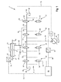
- FIG. 1 an electro-hydraulic arrangement in the form of an electro-hydraulic steering device 1 is shown.
- This has an actuator in the form of a trained as a synchronous cylinder steering cylinder 2, which is controlled by a valve assembly 4.
- the steering cylinder 2 has a piston 6 of the both sides of a piston rod 8 and 10 projects away.
- the piston 6 is limited together with the piston rod 8 and 10, two annular control chambers 12 and 14.
- Die in the FIG. 1 Left control chamber 12 is connected via a first port A1 to a connecting line 16 and the right control chamber 14 via a second port A2 to a connecting line 18.
- the first connecting line 16 branches into a first feed line 20 and a first return line 22.
- the second connecting line 18 branches into a second feed line 24 and a second return line 26.
- the first feed line 20 is connected to a pump line 30 via a first valve group 28.
- the second supply line 24 is likewise connected to the pump line 30 via a second valve group 32.
- the first return line 22 is connected via a third valve group 34 to a tank line 36, which is in fluid communication with a tank 38.
- the second return line 26 is also connected via a fourth valve group 40 to a tank line 42 which is connected to the tank 38.
- the pump line 30 is connected to a pump connection P of an adjustable hydraulic pump 44, via which pressure medium from the tank 38, a tank line 46 and a tank connection T of the hydraulic pump 44 into the pump line 30 can be conveyed.
- the valve groups 28, 32, 34, 40 each have two fluidically parallel valves 48, 50; 52, 54; 56, 58 and 60, 62, respectively.
- the valves designed as switching valves 48 to 62 are 2/2-way valves whose valve slide via a valve spring 64 (see, for example, valve 60) is acted upon in a closed position with a spring force and can be brought via an electric actuator 66 in an open position. It would also be conceivable to provide an additional redundant valve spring to a respective valve spring of the valves 48 to 62, so that upon failure of a valve spring, a further valve spring is provided to act on the valve spool in the direction of its closed position with a spring force.
- the valves 48 to 62 are designed as seat valves.
- a control device 68 in particular a Electronic Control Unit (ECU)
- the controller 68 may be a P controller.
- the effective free flow cross section of the valves 48 to 62 is in this pulsed control of the time-averaged flow cross-section of these valves.
- the control device 68 is connected via a respective electrical control line 70 with a respective electric actuator 66 of the valves 48 to 62, wherein the better representability half only a control line 70 in the FIG. 1 between the control device 68 and the valve 58 is located. For better representability, only one electric actuator 66 is provided with a reference numeral.
- the control device 68 is connected via a signal line 72 to a sensor in the form of a displacement transducer 74. This measures a displacement of the piston 6 via its in the FIG. 1 left piston rod 8 and reports this as Stellungsistwert x_ist to the control device 68. If the piston 6 in the center in its neutral position, the Stellungsistwert x_ist is zero. If the piston 6 in the FIG. 1 shifted to the right, that is, pressure medium flows into the control chamber 12 and from the control chamber 14, so the Stellungsistwert x_ist is greater than zero and increases substantially linearly to the displacement. If the piston 6 from its neutral position in the FIG.
- the Stellungsistwert x_ist is less than zero and decreases substantially linearly with the displacement of the piston 6.
- the Stellungsistwert x_ist is in the control device 8 with a predetermined position setpoint value x_soll is compared and from this a control difference of actual position value x_act and the desired position value x_set is calculated in order to calculate therefrom a manipulated variable u for controlling the valves 48 to 62 in accordance with the control law, the manipulated variable u having a specific pulse-pause ratio in the pulse-width-modulated actuation equivalent.
- the position setpoint x_soll is predetermined, for example, by an operator of the electrohydraulic steering device 1 by pivoting a steering wheel or a control lever.
- the control device 68 for example, simply used as a P controller.
- the adjustable hydraulic pump 44 is set in a conventional manner via a pressure regulator 75, to which via a load-sensing (LS) line 76, the highest load pressure of the control chambers 12 and 14 is reported.
- the LS line 76 is for this purpose connected to an output of a shuttle valve 78, whose first input port 80 with the in the FIG. 1 left connecting line 16 and the second input terminal 82 is connected to the right connecting line 18.
- the pressure regulator 75 is connected to a pressure signaling line 84, which taps the pressure from the pump line 30. Via a pressure sensor 86, the pressure is also tapped from the pump line 30 and reported via a signal line 88 of the control device 68.
- the steering cylinder 2 is coupled to at least one steerable wheel of a mobile work machine, whereby the wheel is deflected at a deflection of the piston 6.
- the control device 68 via in the FIG. 1 not shown means the position setpoint x_soll given, which is greater than zero.
- the actual position value x_ist is measured continuously and a control difference is formed. This is greater than zero as long as the actual position value x_ist differs from the position setpoint x_soll. If the manipulated variable u formed from the control difference is greater than zero, the valves 48 and 50 of the first valve group 28 and the valves 60 and 62 of the fourth valve group 40 are opened, whereby pressure medium from the hydraulic pump 44 into the left control chamber 12 and from the right control chamber 14 flows to the tank 38.
- An effective free flow cross section of the opened valves 48, 50, 60 and 62 is substantially proportional to the size of the manipulated variable u. This means that the larger the manipulated variable u, ie the larger the control difference, the greater the effective free flow cross section. If the manipulated variable u is zero, that is, the position setpoint x_soll corresponds to the actual position value x_act, then the valves 48, 50, 60 and 62 are closed again.
- valves 52, 54 the second valve group and the valves 56 and 58 of the third valve group are opened.
- This allows pressure fluid from the pump 44 in the in the FIG. 1 right control chamber 14 and from the left control chamber 12 to the tank 38 to flow.
- an effective free flow area of the valves 48, 50, 56 and 58 is substantially proportional to the manipulated variable u.
- FIG. 2 is the regulation of the electro-hydraulic steering device 1 from FIG. 1 schematically shown in a block diagram.
- the controller 68 has as an input, as discussed above in FIG. 1 explains, a Stellungsistwert x_ist and a position setpoint x_soll. From this, the control difference is formed and formed according to the governing law a manipulated variable u. If the manipulated variable u is greater than zero, the first valve group 28 and the fourth valve group 40 are actuated and their valves 48, 50 and 60, 62 are opened, whereby the piston 6 of the steering cylinder 2 off FIG. 1 is moved to the right. The second and third valve group 32 and 34 are not driven, whereby their valves 52, 54 and 56, 58 are closed.
- the second valve group 32 and the third valve group 34 are activated, as a result of which their valves 52, 54 and 56, 58 are opened.
- the piston 6 is thereby moved to the left.
- the first and fourth valve group 28, 40 are not driven, whereby their valves 48, 50 and 60, 62 are closed.
- the effective free flow cross-section of the valves 60 and 62 of the fourth valve group 40 and the valves 56 and 58 of the third valve group 34, each open a connection to the tank 38, is smaller by a factor K than the effective free flow area of the remaining valves 48, 50th , 52 and 54 of the first valve group 28 and the second valve group 32.
- the factor K can be selected, for example, such that the effective free flow cross section of the valves 56, 58, 60 and 62 is approximately 70 percent of the effective free flow cross section of the remaining valves 48 to 54.
- valves 56 to 62 are smaller, they have an additional aperture with a fixed cross-section or are controlled differently by the control device 68. If shutters are provided, then it is conceivable to design all valves 48 to 62 the same. Due to the lower effective free Flow cross-section of the valves 56 to 62 prevails in the return, so in the control chamber 12 or 14, which is connected to the tank 38, a higher back pressure. This results in that the piston 6 is subjected to higher compressive forces and thus has a high stability to external forces, which are transmitted, for example, by the at least one steerable wheel of the mobile working machine on this.
- the following describes the operation of the electro-hydraulic steering device 1 when a failure occurs on one of the valves 48 to 62.
- valve 60 in the second return line 26 is defective, in which its valve slide remains in a closed position, the regulation causes the remaining valves 48, 50 and 62 to be opened further.
- valves 48, 50 and 62 are more closed. It is conceivable that a back pressure in the control chamber 14 is no longer sufficient to counteract steering forces acting on the piston. This in turn has the consequence that the piston 6 would move too fast. Too fast movement leads to a sign reversal of the control difference and thus to a connection of the hydraulic pump with the control chamber 14, in which the valves 52 and 54 of the second valve group 32 are opened, while the control chamber 12 is relieved via the valves 56 and 58 of the third valve group 34 to the tank 38. The other valves 48, 50 and 62 are correspondingly closed with the exception of the defective valve 60. The piston 6 can thereby be effectively stopped, whereby a dangerous steering movement is prevented.
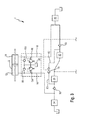
- FIG. 3 a second embodiment of the electro-hydraulic steering device 1 is shown.
- the valve groups 28, 32, 34 and 40 are shown here as blocks. Downstream of the first valve group 28, a check valve 90 which opens in a pressure medium flow direction to the control chamber 12 of the steering cylinder 2 is arranged. Downstream of the second valve group 32, a check valve 92 is also arranged, which opens in a pressure medium flow direction toward the control chamber 14.
- the shuttle valve 78 is connected at its first input port 80 to the pressure medium flow path between the first valve group 28 and the check valve 90 and with its second input port 82 in the pressure medium flow path between the second valve group 32 and the check valve 92.
- the tap of the LS-pressure should only be provided in the inlet, which is why the check valves 90 and 92 are provided.
- pressure regulating valves 94 and 96 and sucking valves 98 and 100 prescribed by law for a steering apparatus are arranged in the electro-hydraulic steering apparatus 1. That in the FIG. 3 Left pressure relief valve 94 opens from a certain pressure in the connecting line 16, a pressure medium connection between the connecting line 16 and the tank 38. Mit the right pressure relief valve 96, a pressure medium connection between the connecting line 18 and the tank 38 is opened at a certain pressure in the connecting line 18. That in the FIG. 3 left Nachsaugventil 98 is designed as a check valve, which opens in a pressure fluid flow direction to the connecting line 16, whereby pressure medium from the tank 38 can be sucked. The right-hand suction valve 100 is designed as a non-return valve opening in the direction of the pressure medium flow toward the connection line 18, via which pressure medium can likewise be sucked in to the tank 38.
- the pressure relief valves 94 and 96 and the Nachsaugventile 98 and 100 according to in the steering apparatus 1 according to FIG. 1 provide by placing these between the connecting lines 16 and 18 in FIG. 1 are arranged.
- the LS pressure in the steering device 1 can be off FIG. 1 in accordance with the steering device FIG. 3 be tapped.
- the check valves 90 and 92 are simply off FIG. 2 in the steering device in FIG. 1 used in the pressure medium flow path between the valve group 28 and 32 and the respective connecting line 16 and 18 respectively.
- the input port 80 and 82 of the shuttle valve 78 from FIG. 1 are then connected in the pressure medium flow path between the valve group 28 and the check valve 90 and between the valve group 32 and the check valve 92.
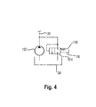
- a hydraulic pump 102 is shown in the form of a fixed displacement pump, which instead of the hydraulic pump 44 from FIG. 1 can be used.
- a proportionally adjustable 2/2-way valve 104 is provided, the valve spool is acted upon in the direction of its closed position with a spring force of a valve spring 106.
- the valve spool is acted upon by the LS pressure via the LS line 76 in the direction of its closed position.
- Via the directional control valve 104 a connection between the pump line 30 and the tank 38 is then controllable.
- valves 48 to 62 off FIG. 1 may alternatively be designed as proportional valves.
- the controller 68 would then valves 48 to 62 each with to drive a current signal that is a function of the control difference.
- a size of the current signal is then approximately proportional to the effective free flow cross section of the actuated valves 48 to 62.
- an electro-hydraulic arrangement in particular an electro-hydraulic steering device, which has an actuator, in particular in the form of a steering cylinder.
- an actuator in particular in the form of a steering cylinder.
- a first connection of the actuator via a first supply line to a pressure medium supply in particular in the form of a hydraulic pump, connectable.
- a second connection of the actuator via a second supply line is also connected to the pressure medium supply.
- the first connection can be connected via a first return line and the second connection can be connected via a second return line to a pressure medium sink.
- a valve group is arranged, each having a plurality of fluidly arranged parallel valves for controlling a pressure medium volume flow.
- a position actual value, in particular an adjustment position, of the actuator is determined and reported to a control device. This forms a control difference from the actual position value and a preset position setpoint. Based on the control difference, an effective free flow cross-section of the valves and thus the actuator is controlled.
- valve assembly 1 electro-hydraulic steering device 2 steering cylinder 4 valve assembly 6 piston 8th piston rod 10 piston rod 12 control chamber 14 control chamber 16 connecting cable 18 connecting cable 20 first supply line 22 first return 24 second supply line 26 second return 28 first valve group 30 pump line 32 second valve group 34 third valve group 36 tank line 38 tank 40 fourth valve group 42 tank line 44 hydraulic pump 46 tank line 48 Valve 50 Valve 52 Valve 54 Valve 56 Valve 58 Valve 60 Valve 62 Valve 64 valve spring 66 electrical actuator 68 control device 70 control line 72 signal line 74 transducer 75 pressure regulator 76 74 input port 84 Pressure signaling line 86 pressure sensor 88 signal line 90 check valve 92 check valve 94 Pressure relief valve 96 Pressure relief valve 98 cavitation valve 100 cavitation valve 102 hydraulic pump 104 way valve 106 valve spring A1 first connection A2 second connection P pump connection T tank connection x_ist Actual position X_SOLL Position setpoint u manipulated variable K factor
Landscapes
- Engineering & Computer Science (AREA)
- Mechanical Engineering (AREA)
- Chemical & Material Sciences (AREA)
- Combustion & Propulsion (AREA)
- Transportation (AREA)
- Physics & Mathematics (AREA)
- Fluid Mechanics (AREA)
- General Engineering & Computer Science (AREA)
- Fluid-Pressure Circuits (AREA)
Applications Claiming Priority (1)
| Application Number | Priority Date | Filing Date | Title |
|---|---|---|---|
| DE102012205939A DE102012205939A1 (de) | 2012-04-12 | 2012-04-12 | Elektrohydraulische Anordnung, Verfahren zur Steuerung der elektrohydraulischen Anordnung und mobile Arbeitsmaschine mit der elektrohydraulischen Anordnung |
Publications (1)
| Publication Number | Publication Date |
|---|---|
| EP2650549A2 true EP2650549A2 (fr) | 2013-10-16 |
Family
ID=47900748
Family Applications (1)
| Application Number | Title | Priority Date | Filing Date |
|---|---|---|---|
| EP20130158868 Withdrawn EP2650549A2 (fr) | 2012-04-12 | 2013-03-13 | Agencement électro-hydraulique, procédé de commande de l'agencement électro-hydraulique et machine de travail mobile dotée de l'arrangement électro-hydraulique |
Country Status (2)
| Country | Link |
|---|---|
| EP (1) | EP2650549A2 (fr) |
| DE (1) | DE102012205939A1 (fr) |
Cited By (7)
| Publication number | Priority date | Publication date | Assignee | Title |
|---|---|---|---|---|
| CN105402205A (zh) * | 2015-12-25 | 2016-03-16 | 江苏恒立液压有限公司 | 油缸负载回路模拟试验装置 |
| CN105736515A (zh) * | 2014-12-08 | 2016-07-06 | 特斯科(上海)机电测试技术有限公司 | 一种下线液压缸的漂移测试方法 |
| CN106640844A (zh) * | 2015-10-30 | 2017-05-10 | 中石化石油工程技术服务有限公司 | 旋转导向液压系统电磁阀组测试装置 |
| US10194430B2 (en) | 2010-03-10 | 2019-01-29 | Lg Electronics Inc. | Method and apparatus for transmitting uplink control information in a wireless communication system |
| EP3397842A4 (fr) * | 2015-12-31 | 2019-08-28 | Westinghouse Electric Company Llc | Appareil hydraulique et machine hydraulique utilisable en son sein |
| CN110520635A (zh) * | 2017-04-28 | 2019-11-29 | 川崎重工业株式会社 | 液压驱动系统 |
| CN115163600A (zh) * | 2022-09-07 | 2022-10-11 | 浙大城市学院 | 一种基于流体控制的大范围纳米级定位系统 |
Families Citing this family (1)
| Publication number | Priority date | Publication date | Assignee | Title |
|---|---|---|---|---|
| CN111677717B (zh) * | 2020-05-19 | 2022-04-08 | 江苏理工学院 | 一种液压阀测试试验台的液压系统 |
Citations (2)
| Publication number | Priority date | Publication date | Assignee | Title |
|---|---|---|---|---|
| WO2007028863A1 (fr) | 2005-09-06 | 2007-03-15 | Lauri Siivonen | Détection de pannes dans un système de valves et contrôle avec tolérance des pannes |
| EP2388178A2 (fr) | 2010-05-17 | 2011-11-23 | Robert Bosch GmbH | Direction électrohydraulique |
Family Cites Families (4)
| Publication number | Priority date | Publication date | Assignee | Title |
|---|---|---|---|---|
| US6575263B2 (en) * | 2001-04-26 | 2003-06-10 | Eaton Corporation | Torque device for electronic steer-by wire steering systems |
| DE102007033986A1 (de) * | 2006-08-08 | 2008-02-14 | Bosch Rexroth Aktiengesellschaft | Hydraulische Lenkeinrichtung mit Stromverstärkung und hydraulischer Sicherheitsfunktion |
| DE102008021973A1 (de) * | 2008-05-02 | 2009-11-05 | Bayerische Motoren Werke Aktiengesellschaft | Fahrzeug- Lenksystem der by-wire-Bauart |
| US8397858B2 (en) * | 2010-06-04 | 2013-03-19 | Eaton Corporation | Hydro-mechanical steering unit with integrated emergency steering capability |
-
2012
- 2012-04-12 DE DE102012205939A patent/DE102012205939A1/de not_active Withdrawn
-
2013
- 2013-03-13 EP EP20130158868 patent/EP2650549A2/fr not_active Withdrawn
Patent Citations (2)
| Publication number | Priority date | Publication date | Assignee | Title |
|---|---|---|---|---|
| WO2007028863A1 (fr) | 2005-09-06 | 2007-03-15 | Lauri Siivonen | Détection de pannes dans un système de valves et contrôle avec tolérance des pannes |
| EP2388178A2 (fr) | 2010-05-17 | 2011-11-23 | Robert Bosch GmbH | Direction électrohydraulique |
Cited By (9)
| Publication number | Priority date | Publication date | Assignee | Title |
|---|---|---|---|---|
| US10194430B2 (en) | 2010-03-10 | 2019-01-29 | Lg Electronics Inc. | Method and apparatus for transmitting uplink control information in a wireless communication system |
| CN105736515A (zh) * | 2014-12-08 | 2016-07-06 | 特斯科(上海)机电测试技术有限公司 | 一种下线液压缸的漂移测试方法 |
| CN106640844A (zh) * | 2015-10-30 | 2017-05-10 | 中石化石油工程技术服务有限公司 | 旋转导向液压系统电磁阀组测试装置 |
| CN105402205A (zh) * | 2015-12-25 | 2016-03-16 | 江苏恒立液压有限公司 | 油缸负载回路模拟试验装置 |
| EP3397842A4 (fr) * | 2015-12-31 | 2019-08-28 | Westinghouse Electric Company Llc | Appareil hydraulique et machine hydraulique utilisable en son sein |
| US10900504B2 (en) | 2015-12-31 | 2021-01-26 | Westinghouse Electric Company Llc | Hydraulic apparatus and hydraulic appliance usable therein |
| CN110520635A (zh) * | 2017-04-28 | 2019-11-29 | 川崎重工业株式会社 | 液压驱动系统 |
| CN110520635B (zh) * | 2017-04-28 | 2020-11-06 | 川崎重工业株式会社 | 液压驱动系统 |
| CN115163600A (zh) * | 2022-09-07 | 2022-10-11 | 浙大城市学院 | 一种基于流体控制的大范围纳米级定位系统 |
Also Published As
| Publication number | Publication date |
|---|---|
| DE102012205939A1 (de) | 2013-10-17 |
Similar Documents
| Publication | Publication Date | Title |
|---|---|---|
| EP2650549A2 (fr) | Agencement électro-hydraulique, procédé de commande de l'agencement électro-hydraulique et machine de travail mobile dotée de l'arrangement électro-hydraulique | |
| DE102005035171A1 (de) | Elektrohydraulische Lenkung | |
| EP0850151A1 (fr) | Dispositif antiroulis d'un vehicule | |
| EP2650548A2 (fr) | Système hydraulique, procédé de commande d'un tel système hydraulique et machine de travail mobile dotée d'un tel système hydraulique | |
| EP3748168B1 (fr) | Système d'entraînement hydraulique à deux pompes et à récupération d'énergie | |
| DE2642337B2 (de) | Steuereinrichtung für einen doppeltwirkenden hydraulischen Motor | |
| DE112013005318T5 (de) | Fluiddruck-Steuervorrichtung für einen Löffelbagger | |
| DE112018002880B4 (de) | Lenksteuerungssystem | |
| EP1722110A2 (fr) | Vanne de contrôle de fluide avec circuit pilote électro-rhéologique ou magnéto-rhéologique | |
| DE19931143A1 (de) | Hydraulische Lenkeinrichtung | |
| EP0628730B1 (fr) | Système hydraulique, particulièrement pour une presse plieuse | |
| WO2013037582A1 (fr) | Dispositif de réglage pour une machine hydrostatique et machine hydrostatique | |
| DE102016205582A1 (de) | Hydraulische Antriebsvorrichtung mit Regenerationsbetrieb | |
| DE102004027971B4 (de) | Hydraulische Lenkeinrichtung | |
| EP1954949B1 (fr) | Dispositif hydraulique de commande | |
| EP2613059A2 (fr) | Dispositif de commande d'un actionneur actionné par un fluide pour un appareil de travail | |
| WO2022089862A1 (fr) | Dispositif de direction hydraulique | |
| DE10011016A1 (de) | Verfahren und hydraulische Lenkeinrichtung zur Notlenkung mit einem Lenkhandrad | |
| DE3844399C2 (de) | Steueranordnung für mehrere unabhängig voneinander betätigbare hydraulische Verbraucher und deren Verwendung | |
| DE60108309T2 (de) | Hydraulischer Schaltkreis einer Arbeitsmaschine | |
| DE4435750C1 (de) | Steuervorrichtung für eine hydrostatische Maschine | |
| DE3418261A1 (de) | Ventilanordnung zur steuerung und ueberwachung des arbeitsdruckes eines hydraulischen verbrauchers | |
| EP1178943A1 (fr) | Dispositif servant a reguler la fonction d'inclinaison d'un mat de levage, notamment pour un chariot a fourche | |
| DE102021208330B3 (de) | Hydraulische Steueranordnung | |
| DE102016209509A1 (de) | Hydraulisches Antriebssystem für Gabelstapler |
Legal Events
| Date | Code | Title | Description |
|---|---|---|---|
| PUAI | Public reference made under article 153(3) epc to a published international application that has entered the european phase |
Free format text: ORIGINAL CODE: 0009012 |
|
| AK | Designated contracting states |
Kind code of ref document: A2 Designated state(s): AL AT BE BG CH CY CZ DE DK EE ES FI FR GB GR HR HU IE IS IT LI LT LU LV MC MK MT NL NO PL PT RO RS SE SI SK SM TR |
|
| AX | Request for extension of the european patent |
Extension state: BA ME |
|
| STAA | Information on the status of an ep patent application or granted ep patent |
Free format text: STATUS: THE APPLICATION HAS BEEN WITHDRAWN |
|
| 18W | Application withdrawn |
Effective date: 20150529 |