EP2650486A2 - Système d'étanchéité d'arbre pour turbines à vapeur - Google Patents
Système d'étanchéité d'arbre pour turbines à vapeur Download PDFInfo
- Publication number
- EP2650486A2 EP2650486A2 EP13163217.6A EP13163217A EP2650486A2 EP 2650486 A2 EP2650486 A2 EP 2650486A2 EP 13163217 A EP13163217 A EP 13163217A EP 2650486 A2 EP2650486 A2 EP 2650486A2
- Authority
- EP
- European Patent Office
- Prior art keywords
- seal
- turbine
- shaft
- disposed
- steam
- Prior art date
- Legal status (The legal status is an assumption and is not a legal conclusion. Google has not performed a legal analysis and makes no representation as to the accuracy of the status listed.)
- Withdrawn
Links
- 238000007789 sealing Methods 0.000 title claims abstract description 23
- 238000000034 method Methods 0.000 claims abstract 5
- 239000003570 air Substances 0.000 claims description 44
- 239000012080 ambient air Substances 0.000 claims description 5
- OKTJSMMVPCPJKN-UHFFFAOYSA-N Carbon Chemical compound [C] OKTJSMMVPCPJKN-UHFFFAOYSA-N 0.000 claims description 4
- 229910052799 carbon Inorganic materials 0.000 claims description 4
- 238000012856 packing Methods 0.000 description 6
- 210000004907 gland Anatomy 0.000 description 3
- 239000013618 particulate matter Substances 0.000 description 3
- 238000004891 communication Methods 0.000 description 2
- 230000003247 decreasing effect Effects 0.000 description 2
- 239000002184 metal Substances 0.000 description 2
- 229910052751 metal Inorganic materials 0.000 description 2
- 230000004323 axial length Effects 0.000 description 1
- 239000002817 coal dust Substances 0.000 description 1
- 230000001627 detrimental effect Effects 0.000 description 1
- 230000000694 effects Effects 0.000 description 1
- 239000012530 fluid Substances 0.000 description 1
- 238000012423 maintenance Methods 0.000 description 1
- 239000000463 material Substances 0.000 description 1
- 238000005259 measurement Methods 0.000 description 1
- 150000002739 metals Chemical class 0.000 description 1
- 238000012986 modification Methods 0.000 description 1
- 230000004048 modification Effects 0.000 description 1
- 239000003607 modifier Substances 0.000 description 1
- 238000005192 partition Methods 0.000 description 1
Images


Classifications
-
- F—MECHANICAL ENGINEERING; LIGHTING; HEATING; WEAPONS; BLASTING
- F01—MACHINES OR ENGINES IN GENERAL; ENGINE PLANTS IN GENERAL; STEAM ENGINES
- F01D—NON-POSITIVE DISPLACEMENT MACHINES OR ENGINES, e.g. STEAM TURBINES
- F01D11/00—Preventing or minimising internal leakage of working-fluid, e.g. between stages
- F01D11/003—Preventing or minimising internal leakage of working-fluid, e.g. between stages by packing rings; Mechanical seals
-
- F—MECHANICAL ENGINEERING; LIGHTING; HEATING; WEAPONS; BLASTING
- F01—MACHINES OR ENGINES IN GENERAL; ENGINE PLANTS IN GENERAL; STEAM ENGINES
- F01D—NON-POSITIVE DISPLACEMENT MACHINES OR ENGINES, e.g. STEAM TURBINES
- F01D11/00—Preventing or minimising internal leakage of working-fluid, e.g. between stages
- F01D11/02—Preventing or minimising internal leakage of working-fluid, e.g. between stages by non-contact sealings, e.g. of labyrinth type
- F01D11/04—Preventing or minimising internal leakage of working-fluid, e.g. between stages by non-contact sealings, e.g. of labyrinth type using sealing fluid, e.g. steam
-
- F—MECHANICAL ENGINEERING; LIGHTING; HEATING; WEAPONS; BLASTING
- F02—COMBUSTION ENGINES; HOT-GAS OR COMBUSTION-PRODUCT ENGINE PLANTS
- F02C—GAS-TURBINE PLANTS; AIR INTAKES FOR JET-PROPULSION PLANTS; CONTROLLING FUEL SUPPLY IN AIR-BREATHING JET-PROPULSION PLANTS
- F02C7/00—Features, components parts, details or accessories, not provided for in, or of interest apart form groups F02C1/00 - F02C6/00; Air intakes for jet-propulsion plants
- F02C7/28—Arrangement of seals
-
- F—MECHANICAL ENGINEERING; LIGHTING; HEATING; WEAPONS; BLASTING
- F05—INDEXING SCHEMES RELATING TO ENGINES OR PUMPS IN VARIOUS SUBCLASSES OF CLASSES F01-F04
- F05D—INDEXING SCHEME FOR ASPECTS RELATING TO NON-POSITIVE-DISPLACEMENT MACHINES OR ENGINES, GAS-TURBINES OR JET-PROPULSION PLANTS
- F05D2220/00—Application
- F05D2220/30—Application in turbines
- F05D2220/31—Application in turbines in steam turbines
-
- F—MECHANICAL ENGINEERING; LIGHTING; HEATING; WEAPONS; BLASTING
- F05—INDEXING SCHEMES RELATING TO ENGINES OR PUMPS IN VARIOUS SUBCLASSES OF CLASSES F01-F04
- F05D—INDEXING SCHEME FOR ASPECTS RELATING TO NON-POSITIVE-DISPLACEMENT MACHINES OR ENGINES, GAS-TURBINES OR JET-PROPULSION PLANTS
- F05D2240/00—Components
- F05D2240/60—Shafts
- F05D2240/63—Glands for admission or removal of fluids from shafts
-
- F—MECHANICAL ENGINEERING; LIGHTING; HEATING; WEAPONS; BLASTING
- F05—INDEXING SCHEMES RELATING TO ENGINES OR PUMPS IN VARIOUS SUBCLASSES OF CLASSES F01-F04
- F05D—INDEXING SCHEME FOR ASPECTS RELATING TO NON-POSITIVE-DISPLACEMENT MACHINES OR ENGINES, GAS-TURBINES OR JET-PROPULSION PLANTS
- F05D2260/00—Function
- F05D2260/60—Fluid transfer
- F05D2260/602—Drainage
- F05D2260/6022—Drainage of leakage having past a seal
Definitions
- the invention relates generally to steam turbines, and more particularly, to a self-contained shaft sealing system for a steam turbine.
- shaft sealing systems have been employed including, for example, labyrinth seals disposed about the shaft ends.
- Labyrinth seals include teeth which enclose but do not contact the shaft, thus forming leakage paths between the seal and the shaft.
- Shaft sealing systems further include air seals, which function mainly to prevent air from entering the steam turbine. Disposed axially inward of the air seals are steam seals, which prevent steam from escaping to the outside of the steam turbine.
- accessories including piping systems, steam seal regulators, gland condensers, and auxiliary boilers are required to support turbine function.
- a brush seal is used with labyrinth seals to reduce leakage, but the foregoing accessories remain necessary to provide proper turbine function.
- the gland condenser is employed to maintain a slight vacuum to draw out air that has passed the air seal in the direction of entering the casing, and to exhaust out steam that has passed the steam seal in the direction of exiting the casing.
- a seal header is typically maintained at a positive pressure and either supplies steam to the annulus inward of the steam seal or dumps steam from the annulus, as required in dependence upon whether steam leakage across the steam seal is exceeds or is exceeded by the leakage out of the internal section of the steam turbine. The positive pressure at the annulus inward of the steam seal precludes entry of air into the turbine.
- labyrinth shaft sealing systems such as those described require the support of an extensive accessory system which does not contribute to the work performed by the turbine. These features increase the footprint of a plant, as well as the maintenance requirements without making any direct contribution to turbine output.
- labyrinth seals or brush seals are used in one alternative to labyrinth seals or brush seals, which have smaller effective clearances than the typical 0.75 mm to 1 mm clearances found in labyrinth seal designs.
- the clearances of labyrinth seals allow for particulate matter in the ambient air to pass through the seals without a problem.
- seal system designs that utilize carbon seals having much smaller clearances however, particulate matter may become trapped in the clearance space, causing seal damage. This presents a challenge, particularly for plants such as, for example, coal-fired plants where particulate matter such as coal dust is common in ambient air.
- a first aspect of the invention provides a first turbine section having a rotating member including a shaft, and a stationary member surrounding the rotating member and defining a steam flow path, and a shaft sealing system.
- the shaft sealing system comprises at least one seal disposed about each of a first end and a second end of the shaft; a first connection line for conducting steam from the first turbine section to a downstream portion of the turbine; wherein the first turbine section is at a low pressure, and each of the first and the second ends of the shaft are at a pressure lower than atmospheric pressure, and wherein the downstream portion of the turbine has a pressure below a pressure of the first turbine section.
- a second aspect of the invention provides a first turbine section having a rotating member including a shaft, and a stationary member surrounding the rotating member and defining a steam flow path, and a shaft sealing system.
- the shaft sealing system comprises at least one seal disposed about each of a first end and a second end of the shaft; a first buffer seal disposed axially outboard of the at least one seal disposed about the first end of the shaft; a second buffer seal disposed axially outboard of the at least one seal disposed about the second end of the shaft; a first connection line for conducting steam from the first turbine section to a downstream portion of the turbine, wherein the downstream portion of the turbine has a pressure below a pressure of the first turbine section, and wherein the first turbine section is at a low pressure, and each of the first and the second ends of the shaft are at a pressure lower than atmospheric pressure.
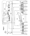
- FIGS. 1-5 show shaft sealing systems in accordance with embodiments of the invention.
- At least one embodiment of the present invention is described below in reference to its application in connection with the operation of a steam turbine. Although embodiments of the invention are illustrated relative to a steam turbine, it is understood that the teachings are equally applicable to other turbomachines including, but not limited to, compressors. Further, at least one embodiment of the present invention is described below in reference to a nominal size and including a set of nominal dimensions. However, it should be apparent to those skilled in the art that the present invention is likewise applicable to any suitable turbine and/or compressor. Further, it should be apparent to those skilled in the art that the present invention is likewise applicable to various scales of the nominal size and/or nominal dimensions.
- Shaft sealing system 100 is self-contained in that the sealing system 100 seals the shaft of a turbine system at the points where the shaft penetrates the casing, preventing steam from escaping the casing and air from entering the casing, without the use of external supporting accessories such as piping systems, steam seal regulators, gland condensers, auxiliary boilers, and the like, which do not contribute to the work performed by the turbine. Therefore, a turbine system including self-contained shaft-sealing system 100 is unencumbered by the previously mentioned accessories and their associated drawbacks.
- a first turbine section 110 having a rotating member 120 including a shaft 130, and a stationary member 140 surrounding the rotating member 120.
- Rotating member 120 and stationary member 140 may be any known rotor and stator structure, respectively.
- First turbine section 110 may be any of a variety of types of turbine sections including but not limited to a low pressure turbine section as shown in FIGS. 1 and 5 , an intermediate pressure turbine section or a high pressure section or a super high pressure section as shown in FIG. 2 , or a high pressure or super high pressure turbine section as shown in FIGS. 3-4 .
- Stationary member 140 further defines a steam flow path 150 having an inlet 160 and an outlet 170 of first turbine section 110.
- Shaft sealing system 100 is disposed about first and second ends 172, 174 of shaft 130.
- first turbine section 110 may be a low pressure turbine section.
- self-contained shaft sealing system 100 may include at least one seal, such as first main seal 180, disposed about first end 172, and at least one seal such as second main seal 181 disposed about second end 174 of shaft 130.
- First and second main seals 180, 181 may each include a single seal or a group of seals.
- First and second main seals 180, 181 may be designed to withstand the main pressure loading in the endpacking, i.e., they withstand significant pressure difference between either side of the seals 180, 181.
- First and second main seals 180, 181 may further include a plurality of packing rings, and in some embodiments may include leak-off lines between each of the plurality of packing rings that loop back into turbine sections to set pressure partition among seal groups and route leakage back to the flowpath to do more work.
- first connection line 200 may be provided at both outlets 170 as shown.
- First connection line 200 is provided for conducting steam from first turbine section 110 to a downstream portion of the turbine.
- the downstream portion may be a condenser 220.
- first connection lines 200 may be disposed axially inboard of each of first and second main seals 180, 181, such that a substantial volume of steam is conducted downstream before reaching main seals 180, 181.
- First connection lines 200 also provide for flow passage in this case.
- the downstream portion of the turbine has a pressure that is lower than that of first turbine section 110, and each end 172, 174 of shaft 130 is maintained at a pressure lower than atmospheric or ambient pressure. Further, in the embodiment of FIG. 1 , all pressure zones located along the axial length of shaft 130 between first end 172 and turbine exhaust, and second end 174 and turbine exhaust are at a pressure that is less than ambient pressure.
- first air seal 184 and second air seal 185 may be provided.
- First and second air seals 184, 185 may be disposed axially outboard of first and second main seals 180, 181 respectively.
- First and second air seals 184, 185 substantially prevent the ingress of ambient air into end packings disposed about shaft 130 ends 172, 174. Egress of steam is substantially prevented in this embodiment by main seals 180, 181 and by a pressure gradient drawing steam from outlet 170 of first turbine section 110 to condenser 220.
- steam enters first turbine section 110 at inlet 160, and follows steam path 150 through successive stages of first turbine section 110 to outlet 170.
- the comparatively low pressure of condenser 220 relative to the pressure in first turbine section 110 causes a majority of the steam to proceed along first connection lines 200 to condenser 220 via outlet 170.
- a small portion of steam may leak off, and rather than proceeding to outlet 170, may reach one of first or second main seals 180, 181.
- Main seals 180, 181, together with the decreasing pressure gradient from first turbine section 110 to condenser 220 substantially cause steam not escape beyond main seals 180, 181, and to be drawn back toward condenser 220.
- first turbine section 110 may be one of a high pressure (HP) or intermediate pressure (IP) section, or a super high pressure (SHP) section in a super critical steam turbine.
- self-contained shaft sealing system 100 may include at least one seal, such as first main seal 180, disposed about first end 172, and at least one seal, such as second main seal 181, disposed about second end 174 of shaft 130.
- first turbine section 110 is a SHP, or HP, or IP turbine section
- the downstream portion may be a low pressure turbine section 210 as shown in FIG. 2 .
- first turbine section 110 may be a HP or SHP turbine section, and the downstream portion may be a combined IP/LP turbine section 215 where the inlet end pressure is above ambient pressure while the exhaust end pressure is below ambient pressure.
- the downstream portion of the turbine i.e. low or intermediate pressure section 210 or 215, has a pressure that is lower than the lowest pressure in the first turbine section 110.
- each end 172, 174 of shaft 130 is maintained at a pressure greater than atmospheric or ambient pressure.
- First and second main seals 180, 181 take the main pressure loading in the endpacking, i.e., they withstand significant pressure difference between either side of the first and second main seals 180, 181. Taking the example of first main seal 180 in FIG. 3 , the pressure on the inside of first main seal 180, i.e.
- First and second main seals 180, 181 may further include a plurality of packing rings, and in some embodiments may include leak-off lines between each of the plurality of packing rings that loop back leakage into turbine sections to do more work.
- first turbine section 110 may further include a first and second steam seal 182, 183 disposed axially outboard of each of the main seals 180, 181 at first and second ends 172, 174 respectively.
- First and second steam seals 182, 183 substantially prevent the egress of steam from first turbine section 110.
- a first annulus 230 may be disposed between first main seal 180 and first steam seal 182 at first end 172 of shaft 130; and a second annulus 240 may be disposed between second main seal 181 and second steam seal 183 at second end 174 of shaft 130.
- a first connection line 200 may further be provided for conducting steam from first turbine section 110 to a downstream portion of the turbine.
- First connection line 200 is disposed such that a first end fluidly connects first and second annuli 230, 240 with each other and with a first stage in low pressure section 210 ( FIG. 2 ) or combined IP/LP section 215 ( FIG. 3 ).
- a first and second air seal 184, 185 may further be provided outboard of first and second steam seals respectively at each end 172, 174 of shaft 130.
- First and second air seals 184, 185 substantially prevent the ingress of air into end packings disposed about shaft 130 ends 172, 174.
- a third annulus 250 may be disposed between first air seal 184 and first steam seal 182 at first end 172 of shaft 130; and a fourth annulus 260 may be disposed between second air seal 185 and second steam seal 183 at second end 174 of shaft 130.
- Third and fourth annuli 250, 260 are fluidly connected by a second connection line 270, to one another and with a second stage 212 in low pressure section 210 ( FIG. 2 ) or IP section 215 ( FIG. 3 ) as applicable.
- the second stage 212 is downstream of first stage 211, and has a lower pressure than both ambient pressure and pressure of the first stage 211. This produces a stronger vacuum effect at third and fourth annuli 250, 260 than at first and second annuli 230, 240.
- first turbine section 110 In operation, with reference to FIGS. 2-3 , steam enters first turbine section 110 at inlet 160, and follows steam path 150 through successive stages of first turbine section 110 to outlet 170.
- the comparatively low pressure of low pressure section 210 ( FIG. 2 ) or intermediate pressure section 215 ( FIG. 3 ) relative to the pressure in first turbine section 110 causes a majority of the steam to proceed along to the respective lower pressure section 210, 215 via outlet 170.
- a small portion of steam may leak off, however, and rather than proceeding to outlet 170, may reach one of first or second main seals 180, 181.
- Main seals 180, 181 together with the decreasing pressure gradient from first turbine section 110 to intermediate 215 ( FIG. 3 ) or low 210 ( FIG.
- First and second annuli 230, 240 in communication with first connection line 200, provide a conduit for delivering this steam into a first stage 211 of low pressure section 210 ( FIG. 2 ) or IP section 215 ( FIG. 3 ) as applicable.
- a vacuum is created at first and second annuli 230, 240, as a result of the comparatively low pressure in first stage 211 as compared to first and second annuli 230, 240, thus drawing the steam into low pressure section 210 ( FIG. 2 ) or IP section 215 ( FIG. 3 ) as applicable.
- First and second steam seals 182, 183 serve to further reduce the amount of steam which may escape first turbine section 110.
- Second connection line 270 together with third and fourth annuli 250, 260, provides a mechanism for capturing any steam which has escaped beyond first and second steam seals 182, 183 and the vacuum created at first and second annuli 230, 240.
- Second connection line 270 delivers steam from third and fourth annuli 250, 260 to a second stage 212 of low pressure section 210 ( FIG. 2 ) or IP section 215 ( FIG. 3 ) as applicable. Because second stage 212 is a later stage in low pressure section 210 ( FIG. 2 ) or IP section 215 ( FIG.
- first and second stages 211, 212 of low pressure section 210 ( FIG. 2 ) or IP section 215 ( FIG. 3 ) provide the necessary pressure gradient to substantially prevent the escape of steam from ends 172, 174, in connection with the previously described seals, using the pressure gradient inherently generated by the turbine system.
- each of the foregoing main seals 180, 181, steam seals 182, 183, and air seals 184, 185 disposed about first and second ends 172, 174 of shaft 130 may be a hydrodynamic non-contacting seal.
- main seals 180, 181; steam seals 182, 183; and air seals 184, 185 may be one of a segmented circumferential seal or a face seal.
- the segmented circumferential seal or face seal may further be made of carbon.
- the steam seals 182, 183, and air seals 184, 185 may have very small clearances relative to shaft 130. For example, such clearances may be less than or equal to about 0.025 mm.
- shaft sealing system 100 may further include a first buffer seal 280 disposed axially outward of the at least one seal, including main seal 180 and steam seal 182 and/or air seal 184 where present.
- Shaft sealing system 100 may further include a second buffer seal 290 disposed axially outward of the at least one seal, including second main seal 181 and steam seal 183 and/or air seal 185 where present.
- a filtered air supply 305 and a filtered air supply line 300 may further be provided.
- Filtered air supply line 300 may place filtered air supply 305 in fluid communication with each of a first cavity 310 and a second cavity 320, such that filtered air can be conducted from filtered air supply 305 to first and second cavities 310, 320.
- Filtered air supply line 300 provides clean, substantially particulate-free air to the environment, aiding in providing a tight seal with rotating member 120.
- First cavity 310 may be disposed between first buffer seal 280 and the axially outermost seal of the at least one seal 180, 182, 184; and second cavity 320 may be disposed between the second buffer seal 290 and the axially outermost seal of the at least one seal 181, 183, 185 where present.
- first cavity 310 is disposed between first air seal 184 and first buffer seal 280.
- Second cavity 320 is disposed between second buffer seal 290 and second air seal 185.
- filtered air supply line 300 may deliver filtered air from filtered air supply 305 to each of first and second cavities 310, 320 in first turbine section 110, as well as similarly disposed first and second cavities 310, 320 in a downstream lower pressure section 210.
- the terms “first,” “second,” and the like, do not denote any order, quantity, or importance, but rather are used to distinguish one element from another, and the terms “a” and “an” herein do not denote a limitation of quantity, but rather denote the presence of at least one of the referenced item.
- the modifier “about” used in connection with a quantity is inclusive of the stated value and has the meaning dictated by the context (e.g., includes the degree of error associated with measurement of the particular quantity).
- the suffix "(s)” as used herein is intended to include both the singular and the plural of the term that it modifies, thereby including one or more of that term (e.g., the metal(s) includes one or more metals).
- Ranges disclosed herein are inclusive and independently combinable (e.g., ranges of "up to about 25 mm, or, more specifically, about 5 mm to about 20 mm,” is inclusive of the endpoints and all intermediate values of the ranges of "about 5 mm to about 25 mm,” etc.).
Landscapes
- Engineering & Computer Science (AREA)
- Mechanical Engineering (AREA)
- General Engineering & Computer Science (AREA)
- Chemical & Material Sciences (AREA)
- Combustion & Propulsion (AREA)
- Turbine Rotor Nozzle Sealing (AREA)
- Sealing Using Fluids, Sealing Without Contact, And Removal Of Oil (AREA)
Applications Claiming Priority (1)
| Application Number | Priority Date | Filing Date | Title |
|---|---|---|---|
| US13/446,696 US20130270775A1 (en) | 2012-04-13 | 2012-04-13 | Shaft sealing system for steam turbines |
Publications (2)
| Publication Number | Publication Date |
|---|---|
| EP2650486A2 true EP2650486A2 (fr) | 2013-10-16 |
| EP2650486A3 EP2650486A3 (fr) | 2018-02-21 |
Family
ID=48050573
Family Applications (1)
| Application Number | Title | Priority Date | Filing Date |
|---|---|---|---|
| EP13163217.6A Withdrawn EP2650486A3 (fr) | 2012-04-13 | 2013-04-10 | Système d'étanchéité d'arbre pour turbines à vapeur |
Country Status (5)
| Country | Link |
|---|---|
| US (1) | US20130270775A1 (fr) |
| EP (1) | EP2650486A3 (fr) |
| JP (1) | JP6239844B2 (fr) |
| CN (1) | CN103375189B (fr) |
| RU (1) | RU2013116548A (fr) |
Families Citing this family (2)
| Publication number | Priority date | Publication date | Assignee | Title |
|---|---|---|---|---|
| CN105508621B (zh) * | 2016-02-01 | 2017-12-01 | 重庆齿轮箱有限责任公司 | 一种密封装置及一种油汽组合密封装置 |
| US11199103B2 (en) * | 2018-09-06 | 2021-12-14 | General Electric Company | Seal assembly for a turbomachine |
Family Cites Families (17)
| Publication number | Priority date | Publication date | Assignee | Title |
|---|---|---|---|---|
| US3873817A (en) * | 1972-05-03 | 1975-03-25 | Westinghouse Electric Corp | On-line monitoring of steam turbine performance |
| CH550348A (de) * | 1972-10-11 | 1974-06-14 | Bbc Brown Boveri & Cie | Sperrmedium-labyrinthdichtung. |
| US3885822A (en) * | 1974-06-21 | 1975-05-27 | Westinghouse Electric Corp | Automatic load and vacuum sensitive exhaust hood spray system |
| US3945760A (en) * | 1974-10-29 | 1976-03-23 | Westinghouse Electric Corporation | Outer cylinder for a low pressure turbine apparatus |
| US4350345A (en) * | 1981-04-01 | 1982-09-21 | General Electric Company | Air-sealed oil deflector |
| US4725196A (en) * | 1986-09-19 | 1988-02-16 | Hitachi, Ltd. | Single-shaft multi-stage centrifugal compressor |
| US5137284A (en) * | 1990-03-16 | 1992-08-11 | Stein Seal Company | Stationary seal ring assembly for use in dry gas face seal assemblies |
| US5749227A (en) * | 1995-06-07 | 1998-05-12 | Electric Boat Corporation | Steam seal air removal system |
| CN1399706A (zh) * | 1999-10-12 | 2003-02-26 | Alm开发公司 | 用于涡轮机的轴承润滑系统 |
| JP3877992B2 (ja) * | 2001-10-17 | 2007-02-07 | 株式会社タンケンシールセーコウ | スチームタービン用軸封装置 |
| US20050206088A1 (en) * | 2004-03-16 | 2005-09-22 | Anderson James H | Bearing seal with backup device |
| US20060062504A1 (en) * | 2004-09-23 | 2006-03-23 | Wilton Stephen A | Lubricant distribution weir for lubricating moving machine elements |
| CN2833118Y (zh) * | 2005-09-07 | 2006-11-01 | 朱恒军 | 新型汽轮机轴封系统 |
| CN201292865Y (zh) * | 2008-12-04 | 2009-08-19 | 东北电力科学研究院有限公司 | 汽轮机低压轴封密封装置 |
| JP5738184B2 (ja) * | 2009-06-16 | 2015-06-17 | 三菱重工業株式会社 | 軸シール装置 |
| US8545166B2 (en) * | 2010-07-28 | 2013-10-01 | General Electric Company | System and method for controlling leak steam to steam seal header for improving steam turbine performance |
| JP5714945B2 (ja) * | 2010-12-27 | 2015-05-07 | 株式会社神戸製鋼所 | 水噴射式スクリュ圧縮機 |
-
2012
- 2012-04-13 US US13/446,696 patent/US20130270775A1/en not_active Abandoned
-
2013
- 2013-04-10 EP EP13163217.6A patent/EP2650486A3/fr not_active Withdrawn
- 2013-04-11 JP JP2013082580A patent/JP6239844B2/ja active Active
- 2013-04-12 RU RU2013116548/06A patent/RU2013116548A/ru not_active Application Discontinuation
- 2013-04-12 CN CN201310125994.5A patent/CN103375189B/zh active Active
Non-Patent Citations (1)
| Title |
|---|
| None |
Also Published As
| Publication number | Publication date |
|---|---|
| US20130270775A1 (en) | 2013-10-17 |
| CN103375189B (zh) | 2016-03-16 |
| CN103375189A (zh) | 2013-10-30 |
| JP6239844B2 (ja) | 2017-11-29 |
| EP2650486A3 (fr) | 2018-02-21 |
| RU2013116548A (ru) | 2014-10-20 |
| JP2013221510A (ja) | 2013-10-28 |
Similar Documents
| Publication | Publication Date | Title |
|---|---|---|
| US10151240B2 (en) | Mid-turbine frame buffer system | |
| US9567908B2 (en) | Mitigating vortex pumping effect upstream of oil seal | |
| US8714907B2 (en) | Arrangement comprising a shaft seal | |
| US10344608B2 (en) | Seal arrangement in a turbine and method for confining the operating fluid | |
| US20090050410A1 (en) | Methods and systems for sealing rotating machines | |
| EP2650485B1 (fr) | Système d'étanchéité d'arbre pour turbines à vapeur | |
| CN105587346A (zh) | 密封装置以及涡轮机械 | |
| CN104632290A (zh) | 旋转机器第二密封组件及其组装方法 | |
| US9175576B2 (en) | Turbomachine | |
| RU2560971C2 (ru) | Система, включающая в себя уплотнение вала | |
| JP2003513188A (ja) | ターボマシンで軸方向スラストを補償する装置 | |
| EP2650486A2 (fr) | Système d'étanchéité d'arbre pour turbines à vapeur | |
| US10808725B2 (en) | Turbomachine and method of operating a turbomachine | |
| US10392956B2 (en) | Sealing system for a steam turbine, and steam turbine | |
| US9791047B2 (en) | Magnetic seal system with internal cooling | |
| US5577885A (en) | Condensing turbine having at least two seals for sealing off the turbine casing | |
| JP6896361B2 (ja) | シャフトシールシステム及び排ガスターボチャージャ | |
| US20100284782A1 (en) | Steam turbine, system, and method of operation | |
| RU2657403C1 (ru) | Сальник вала, способ эксплуатации | |
| JP2019127898A (ja) | 遠心圧縮機 | |
| US8123462B2 (en) | Pressurized sealed chamber between multiple pressurized casings of machine and related method |
Legal Events
| Date | Code | Title | Description |
|---|---|---|---|
| PUAI | Public reference made under article 153(3) epc to a published international application that has entered the european phase |
Free format text: ORIGINAL CODE: 0009012 |
|
| AK | Designated contracting states |
Kind code of ref document: A2 Designated state(s): AL AT BE BG CH CY CZ DE DK EE ES FI FR GB GR HR HU IE IS IT LI LT LU LV MC MK MT NL NO PL PT RO RS SE SI SK SM TR |
|
| AX | Request for extension of the european patent |
Extension state: BA ME |
|
| PUAL | Search report despatched |
Free format text: ORIGINAL CODE: 0009013 |
|
| AK | Designated contracting states |
Kind code of ref document: A3 Designated state(s): AL AT BE BG CH CY CZ DE DK EE ES FI FR GB GR HR HU IE IS IT LI LT LU LV MC MK MT NL NO PL PT RO RS SE SI SK SM TR |
|
| AX | Request for extension of the european patent |
Extension state: BA ME |
|
| RIC1 | Information provided on ipc code assigned before grant |
Ipc: F01D 11/00 20060101AFI20180116BHEP Ipc: F01D 11/04 20060101ALI20180116BHEP |
|
| STAA | Information on the status of an ep patent application or granted ep patent |
Free format text: STATUS: REQUEST FOR EXAMINATION WAS MADE |
|
| 17P | Request for examination filed |
Effective date: 20180821 |
|
| RBV | Designated contracting states (corrected) |
Designated state(s): AL AT BE BG CH CY CZ DE DK EE ES FI FR GB GR HR HU IE IS IT LI LT LU LV MC MK MT NL NO PL PT RO RS SE SI SK SM TR |
|
| STAA | Information on the status of an ep patent application or granted ep patent |
Free format text: STATUS: EXAMINATION IS IN PROGRESS |
|
| 17Q | First examination report despatched |
Effective date: 20181012 |
|
| STAA | Information on the status of an ep patent application or granted ep patent |
Free format text: STATUS: EXAMINATION IS IN PROGRESS |
|
| STAA | Information on the status of an ep patent application or granted ep patent |
Free format text: STATUS: THE APPLICATION IS DEEMED TO BE WITHDRAWN |
|
| 18D | Application deemed to be withdrawn |
Effective date: 20210611 |