EP2650182A1 - Brake control system - Google Patents
Brake control system Download PDFInfo
- Publication number
- EP2650182A1 EP2650182A1 EP13175609.0A EP13175609A EP2650182A1 EP 2650182 A1 EP2650182 A1 EP 2650182A1 EP 13175609 A EP13175609 A EP 13175609A EP 2650182 A1 EP2650182 A1 EP 2650182A1
- Authority
- EP
- European Patent Office
- Prior art keywords
- operating voltage
- minimum operating
- actuating
- brake
- hydraulic pressure
- Prior art date
- Legal status (The legal status is an assumption and is not a legal conclusion. Google has not performed a legal analysis and makes no representation as to the accuracy of the status listed.)
- Granted
Links
Images


Classifications
-
- B—PERFORMING OPERATIONS; TRANSPORTING
- B60—VEHICLES IN GENERAL
- B60T—VEHICLE BRAKE CONTROL SYSTEMS OR PARTS THEREOF; BRAKE CONTROL SYSTEMS OR PARTS THEREOF, IN GENERAL; ARRANGEMENT OF BRAKING ELEMENTS ON VEHICLES IN GENERAL; PORTABLE DEVICES FOR PREVENTING UNWANTED MOVEMENT OF VEHICLES; VEHICLE MODIFICATIONS TO FACILITATE COOLING OF BRAKES
- B60T13/00—Transmitting braking action from initiating means to ultimate brake actuator with power assistance or drive; Brake systems incorporating such transmitting means, e.g. air-pressure brake systems
- B60T13/10—Transmitting braking action from initiating means to ultimate brake actuator with power assistance or drive; Brake systems incorporating such transmitting means, e.g. air-pressure brake systems with fluid assistance, drive, or release
- B60T13/66—Electrical control in fluid-pressure brake systems
- B60T13/68—Electrical control in fluid-pressure brake systems by electrically-controlled valves
- B60T13/686—Electrical control in fluid-pressure brake systems by electrically-controlled valves in hydraulic systems or parts thereof
-
- B—PERFORMING OPERATIONS; TRANSPORTING
- B60—VEHICLES IN GENERAL
- B60T—VEHICLE BRAKE CONTROL SYSTEMS OR PARTS THEREOF; BRAKE CONTROL SYSTEMS OR PARTS THEREOF, IN GENERAL; ARRANGEMENT OF BRAKING ELEMENTS ON VEHICLES IN GENERAL; PORTABLE DEVICES FOR PREVENTING UNWANTED MOVEMENT OF VEHICLES; VEHICLE MODIFICATIONS TO FACILITATE COOLING OF BRAKES
- B60T13/00—Transmitting braking action from initiating means to ultimate brake actuator with power assistance or drive; Brake systems incorporating such transmitting means, e.g. air-pressure brake systems
- B60T13/10—Transmitting braking action from initiating means to ultimate brake actuator with power assistance or drive; Brake systems incorporating such transmitting means, e.g. air-pressure brake systems with fluid assistance, drive, or release
- B60T13/12—Transmitting braking action from initiating means to ultimate brake actuator with power assistance or drive; Brake systems incorporating such transmitting means, e.g. air-pressure brake systems with fluid assistance, drive, or release the fluid being liquid
- B60T13/16—Transmitting braking action from initiating means to ultimate brake actuator with power assistance or drive; Brake systems incorporating such transmitting means, e.g. air-pressure brake systems with fluid assistance, drive, or release the fluid being liquid using pumps directly, i.e. without interposition of accumulators or reservoirs
- B60T13/161—Systems with master cylinder
- B60T13/165—Master cylinder integrated or hydraulically coupled with booster
-
- B—PERFORMING OPERATIONS; TRANSPORTING
- B60—VEHICLES IN GENERAL
- B60T—VEHICLE BRAKE CONTROL SYSTEMS OR PARTS THEREOF; BRAKE CONTROL SYSTEMS OR PARTS THEREOF, IN GENERAL; ARRANGEMENT OF BRAKING ELEMENTS ON VEHICLES IN GENERAL; PORTABLE DEVICES FOR PREVENTING UNWANTED MOVEMENT OF VEHICLES; VEHICLE MODIFICATIONS TO FACILITATE COOLING OF BRAKES
- B60T13/00—Transmitting braking action from initiating means to ultimate brake actuator with power assistance or drive; Brake systems incorporating such transmitting means, e.g. air-pressure brake systems
- B60T13/10—Transmitting braking action from initiating means to ultimate brake actuator with power assistance or drive; Brake systems incorporating such transmitting means, e.g. air-pressure brake systems with fluid assistance, drive, or release
- B60T13/66—Electrical control in fluid-pressure brake systems
- B60T13/662—Electrical control in fluid-pressure brake systems characterised by specified functions of the control system components
-
- B—PERFORMING OPERATIONS; TRANSPORTING
- B60—VEHICLES IN GENERAL
- B60T—VEHICLE BRAKE CONTROL SYSTEMS OR PARTS THEREOF; BRAKE CONTROL SYSTEMS OR PARTS THEREOF, IN GENERAL; ARRANGEMENT OF BRAKING ELEMENTS ON VEHICLES IN GENERAL; PORTABLE DEVICES FOR PREVENTING UNWANTED MOVEMENT OF VEHICLES; VEHICLE MODIFICATIONS TO FACILITATE COOLING OF BRAKES
- B60T8/00—Arrangements for adjusting wheel-braking force to meet varying vehicular or ground-surface conditions, e.g. limiting or varying distribution of braking force
- B60T8/32—Arrangements for adjusting wheel-braking force to meet varying vehicular or ground-surface conditions, e.g. limiting or varying distribution of braking force responsive to a speed condition, e.g. acceleration or deceleration
- B60T8/34—Arrangements for adjusting wheel-braking force to meet varying vehicular or ground-surface conditions, e.g. limiting or varying distribution of braking force responsive to a speed condition, e.g. acceleration or deceleration having a fluid pressure regulator responsive to a speed condition
- B60T8/40—Arrangements for adjusting wheel-braking force to meet varying vehicular or ground-surface conditions, e.g. limiting or varying distribution of braking force responsive to a speed condition, e.g. acceleration or deceleration having a fluid pressure regulator responsive to a speed condition comprising an additional fluid circuit including fluid pressurising means for modifying the pressure of the braking fluid, e.g. including wheel driven pumps for detecting a speed condition, or pumps which are controlled by means independent of the braking system
- B60T8/4072—Systems in which a driver input signal is used as a control signal for the additional fluid circuit which is normally used for braking
- B60T8/4081—Systems with stroke simulating devices for driver input
Definitions
- the invention relates to a brake control system that applies braking forces to wheels.
- the brake control system controls braking forces for wheels so that the optimum braking forces are applied to the vehicle according to a situation in which the vehicle is traveling.
- wheel cylinder pressures for the wheels are monitored using pressure sensors, and electromagnetic valves are controlled so that the wheel cylinder pressures are equal to target hydraulic pressures calculated based on the amount by which a driver depresses a brake pedal.
- pumps are used to increase the hydraulic pressures
- the electromagnetic valves are used to control the hydraulic pressures.
- the actuators such as the pumps and the electromagnetic valves, operate using power from a battery that functions as a power supply. Therefore, it is necessary to examine how the brake control system should execute a brake control if a voltage decreases due to a malfunction of the battery.
- JP-A-10-503446 describes a circuit for a brake system that executes an electrical control of braking force distribution.
- the function for executing the electrical braking force distribution control is maintained until the voltage of a power supply falls below a predetermined limit value.
- the function of the Antilock Brake System (ABS) and the function of the Traction Control System (TCS) are suppressed.
- the invention provides a brake control system that makes it possible to control actuators in a simple manner when the voltage of a power supply decreases.
- An aspect of the invention relates to a brake control system that includes a power supply portion that supplies a voltage to a plurality of actuators; a first actuator that operates to perform a first function when the first actuator is supplied with a voltage equal to or higher than a first minimum operating voltage from the power supply portion; and a second actuator that operates to perform a second function when the second actuator is supplied with a voltage equal to or higher than a second minimum operating voltage from the power supply portion.
- the first minimum operating voltage and the second minimum operating voltage are set different from each other by a predetermined value so that the first actuator and the second actuator stop operating in a predetermined sequence with a decrease in the supplied voltage.
- the actuators stop operating in the predetermined sequence, although no particular control is executed.
- the actuators stop operating in the predetermined sequence, although no particular control is executed.
- the first minimum operating voltage and the second minimum operating voltage may be set different from each other by the predetermined value so that a first minimum operating voltage range does not overlap a second minimum operating voltage range.
- the first minimum operating voltage range is a range of variation in the first minimum operating voltage for the first actuator due to manufacturing variance
- the second minimum operating voltage range is a range of variation in the second minimum operating voltage for the second actuator due to manufacturing variance.
- a maximum value in the first minimum operating voltage range may be lower than a minimum value in the second minimum operating voltage range.
- the first actuator may include a sensor that detects whether a driver is performing a braking operation; and the second actuator may include a motor that operates a pump, and an electromagnetically-controlled valve that is controlled by controlling an electric current supplied to the electromagnetically-controlled valve.
- the sensor continues to detect whether the driver is performing the braking operation until a time later than a time at which the motor and the electromagnetically-controlled valve stop operating. Accordingly, it is possible to increase the period during which the motor and the electromagnetically-controlled valve are controlled based on the output from the sensor.
- the first actuator may include a first electromagnetically-controlled valve that is normally closed, and when the first electromagnetically-controlled valve is closed, the first electromagnetically-controlled valve may interrupt discharge of operating fluid from a wheel cylinder; and the second actuator may include a second electromagnetically-controlled valve that is normally open, and when the second electromagnetically-controlled valve is closed, the second electromagnetically-controlled valve may interrupt communication between a master cylinder and the wheel cylinder.
- the first electromagnetically-controlled valve stops operating after the second electromagnetically-controlled valve stops operating. Accordingly, it is possible to avoid the situation in which the first electromagnetically-controlled valve stops operating before the second electromagnetically-controlled valve stops operating, and thus, it is possible to avoid the situation in which the hydraulic pressure in the wheel cylinder cannot be decreased.
- the first actuator may control a braking force applied to a front wheel; and the second actuator may control a braking force applied to a rear wheel.
- the first actuator for the front wheel stops operating after the second actuator for the rear wheel stops operating.
- the first actuator includes a plurality of first actuators, and at least one of the plurality of first actuators belongs to a first brake system and at least another one of the plurality of first actuators belongs to a second brake system that is separately controlled from the first brake system
- the second actuator includes a plurality of second actuators, and at least one of the plurality of second actuators belongs to the first brake system and at least another one of the plurality of second actuators belongs to the second brake system
- a maximum value in the first minimum operating voltage range for the one of the plurality of first actuators belonging to the first brake system may be lower than a minimum value in the first minimum operating voltage range for the another one of the plurality of first actuators belonging to the second brake system
- a maximum value in the second minimum operating voltage range for the one of the plurality of second actuators belonging to the first brake system may be lower than a minimum value in the second minimum operating voltage range for the another one of the plurality of second actuators belonging to the second brake system.
- the brake control system it is possible to suppress an increase in the cost, and to control the actuators in a simple manner when the voltage of the power supply decreases.
- the invention can provide a number of advantageous features and benefits. It is to be understood that, in practicing the invention, embodiments can be constructed to include one or more features or benefits of embodiments disclosed herein, but not include other features or benefits. Accordingly, it is to be understood that the preferred embodiments discussed herein are provided as examples and are not to be construed as limiting, particularly since embodiments can be formed to practice the invention that do not include each of the features of the disclosed examples.
- FIG. 1 is a schematic diagram showing a configuration of a brake control system 100 according to an exemplary embodiment of the invention.
- FIG. 1 shows an example in which the brake control system 100 according to the embodiment is applied to a vehicle in which hydraulic circuits of a piping system are configured.
- the piping system can be directed to a piping system for a front-right wheel and a rear-left wheel, and a piping system for a front-left wheel and a rear-right wheel.
- the same elements are denoted by the same reference numerals, and redundant description thereof will be omitted as appropriate.
- the brake control system 100 includes a brake pedal 1, a stroke sensor 2, a master cylinder 3, a stroke control valve 30, a stroke simulator 4, a brake hydraulic pressure control actuator 5, a wheel cylinder 6FL for a front-left wheel FL (hereinafter, may be referred to as "front-left wheel cylinder 6FL”), a wheel cylinder 6FR for a front-right wheel FR (hereinafter, may be referred to as “front-right wheel cylinder 6FR”), a wheel cylinder 6RL for a rear-left wheel RL (hereinafter, may be referred to as "rear-left wheel cylinder 6RL”), and a wheel cylinder 6RR for a rear-right wheel RR (hereinafter, may be referred to as "rear-right wheel cylinder 6RR").
- front-left wheel cylinder 6FL for a front-left wheel FL
- a wheel cylinder 6FR for a front-right wheel FR
- a wheel cylinder 6RL for a rear-left wheel RL
- the brake control system 100 also includes a brake ECU 200.
- the brake ECU 200 is a control portion that controls portions of the brake control system 100.
- brake fluid is supplied to the wheel cylinders 6 through the hydraulic circuits.
- hydraulic pressures i.e., wheel cylinder pressures
- Each wheel cylinder 6 may include a corresponding brake disc (not shown) and a corresponding brake caliper (not shown).
- a unit including the wheel cylinder, the brake disc, and the brake caliper is referred to as "a disc brake unit”.
- a pedal stroke which is the operation amount of the brake pedal 1
- the stroke sensor 2 outputs a detection signal corresponding to the pedal stroke.
- the detection signal is input to the brake ECU 200, and the brake ECU 200 detects the pedal stroke of the brake pedal 1.
- a brake light switch 19 changes its states between on-state and off-state, thereby the brake light switch 19 detects whether a driver is performing a brake operation.
- the detection signal by the brake light switch 19 is also input to the brake ECU 200.
- the stroke sensor 2 is employed as an operation amount sensor that detects the operation amount of a brake operating member.
- a depression force sensor that detects a depression force applied to the brake pedal 1 may be employed as the operation amount sensor.
- the brake pedal 1 is connected to a push rod or the like that transmits the pedal stroke to a master cylinder 3.
- a master cylinder pressure is generated in each of a primary chamber 3a and a secondary chamber 3b of the master cylinder 3.
- the master cylinder 3 includes a primary piston 3c and a secondary piston 3d.
- the primary chamber 3a and the secondary chamber 3b are formed using the primary piston 3c and the secondary piston 3d.
- the primary piston 3c and the secondary piston 3d receive the elastic force of a spring 3e. Therefore, when the brake pedal 1 is released, each of the pistons 3c and 3d is pressed by the elastic force of the spring 3, and thus the brake pedal 1 returns to an initial position.
- a pipe passage B is connected to the primary chamber 3a of the master cylinder 3, and a pipe passage K is connected to the secondary chamber 3b of the master cylinder 3.
- the pipe passage B and the pipe passage K extend toward the brake hydraulic pressure control actuator 5.
- the master cylinder 3 includes a reservoir tank 3f.
- the reservoir tank 3f When the brake pedal 1 is at the initial position, the reservoir tank 3f is connected to the primary chamber 3a and to the secondary chamber 3b through respective passages (not shown).
- the reservoir tank 3f supplies the brake fluid into the master cylinder 3.
- Surplus brake fluid in the master cylinder 3 is stored in the reservoir tank 3f.
- the reservoir tank 3f is connected to pipe passages C and D that extend toward the brake hydraulic pressure control actuator 5.
- a stroke simulator 4 is connected to a pipe passage E that is connected to the pipe passage K.
- the brake fluid flowing from the secondary chamber 3b is stored in the stroke simulator 4.
- the stroke control valve 30 is provided in the pipe passage E.
- the stroke control valve 30 is a normally-closed two position valve that opens and closes the pipe passage E, that is, controls the state of the pipe passage E.
- the stroke control valve 30 controls the flow of the brake fluid to the stroke simulator 4.
- a pipe passage F is provided in the brake hydraulic pressure control actuator 5.
- the pipe passage F is connected to the pipe passage K so that the secondary chamber 3b of the master cylinder 3 is connected to the wheel cylinder 6FR for the front-right wheel FR.
- a shutoff valve 36 is provided in the pipe passage F.
- the shutoff valve 36 is a two position valve that is open (to allow the brake fluid to flow) when de-energized, and closed (to interrupt the flow of the brake fluid) when energized.
- the shutoff valve 36 opens and closes the pipe passage F, that is, controls the state of the pipe passage F, thereby controlling the supply of the brake fluid to the wheel cylinder 6FR through the pipe passages K and F.
- a pipe passage G is provided in the brake hydraulic pressure control actuator 5.
- the pipe passage G is connected to the pipe passage B so that the primary chamber 3a of the master cylinder 3 is connected to the wheel cylinder 6FL for the front-left wheel FL.
- a shutoff valve 37 is provided in the pipe passage G.
- the shutoff valve 37 is a two position valve that is open when de-energized, and closed when energized.
- the shutoff valve 37 opens and closes the pipe passage G, that is, controls the state of the pipe passage G, thereby controlling the supply of the brake fluid to the wheel cylinder 6FL through the pipe passages B and G.
- a pipe passage H and a pipe passage I are provided in the brake hydraulic pressure control actuator 5.
- the pipe passage H is connected to a pipe passage C that extends from the reservoir tank 3f.
- the pipe passage I is connected to a pipe passage D that extends from the reservoir tank 3f.
- the pipe passage H branches into two pipe passages H1 and H2.
- the pipe passage H1 is connected to the front-right wheel cylinder 6FR, and the pipe passage H2 is connected to the rear-left wheel cylinder 6RL.
- the pipe passage I branches into two pipe passages I3 and I4.
- the pipe passage I3 is connected to the front-left wheel cylinder 6FL, and the pipe passage I4 is connected to the rear-right wheel cylinder 6RR.
- the front-right wheel cylinder 6FR and the front-left wheel cylinder 6FL are the wheel cylinder for the front-right wheel FR and the wheel cylinder for the front-left wheel FL, respectively.
- the rear-left wheel cylinder 6RL and the rear-right wheel cylinder 6RR are the wheel cylinder for the rear-left wheel RL and the wheel cylinder for the rear-right wheel RR, respectively.
- Pumps 7, 8, 9, and 10 are provided in the pipe passages H1, H2, I3, and I4, respectively. Namely, one pump is provided in each of the pipe passages H1, H2, I3, and I4.
- Each of the pumps 7 to 10 is, for example, a trochoidal pump that does not make much noise.
- the two pumps 7 and 8 are operated by a first motor 11, and the two pumps 9 and 10 are operated by a second motor 12.
- the first motor 11 and the second motor 12 operate the pumps 7 to 10 in accordance with the operation of the brake pedal 1.
- the brake fluid is supplied to the wheel cylinders 6 through the pumps 7 to 10.
- the four pumps 7 to 10 function as a hydraulic pressure source.
- the pumps 7 to 10 are provided in the hydraulic circuits.
- the pumps 7 and 8 supply the brake fluid to the wheel cylinders 6FR, 6RL in accordance with the rotational speed of the first motor 11 connected to the pumps 7 and 8.
- the pumps 9 and 10 supply the brake fluid to the wheel cylinders 6FL 6RR in accordance with the rotational speed of the second motor 12 connected to the pumps 9 and 10. Namely, two pumps are operated by one motor, and each of the two pumps is connected to one corresponding wheel cylinder.
- a common battery may supply electric power to the first motor 11 and the second motor 12.
- the pumps 7 to 10 supply the brake fluid to the wheel cylinders 6, thereby applying the wheel cylinder pressures.
- Pipe passages J1, J2, J3, and J4 are connected in parallel to the pumps 7, 8, 9, and 10, respectively.
- a communication valve 38 and a hydraulic pressure adjusting valve 32 are provided in the pipe passage J1 that is connected in parallel to the pump 7.
- the communication valve 38 and the hydraulic pressure adjusting valve 32 are connected in series to each other.
- the communication valve 38 and the hydraulic pressure adjusting valve 32 are arranged such that the communication valve 38 is positioned on the side of an intake port of the pump 7 (i.e., the communication valve 38 is positioned at a downstream side of the pipe passage J1 in a direction in which the brake fluid flows), and the hydraulic pressure adjusting valve 32 is positioned on the side of a discharge port of the pump 7 (i.e., the hydraulic pressure adjusting valve 32 is positioned at an upstream side of the pipe passage J1 in the direction in which the brake fluid flows).
- the communication valve 38 allows the brake fluid to flow between the reservoir tank 3f and the hydraulic pressure adjusting valve 32, and interrupts the flow of the brake fluid between the reservoir tank 3f and the hydraulic pressure adjusting valve 32.
- the communication valve 38 is a two position valve that is closed when de-energized, and open when energized.
- the hydraulic pressure adjusting valve 32 is a normally-open linear valve which is open when de-energized, and closed when energized, and whose opening degree is adjusted by controlling an electric current supplied to the hydraulic pressure adjusting valve 32.
- Forces F1, F2, F3, and F4 act on the hydraulic pressure adjusting valve 32.
- F1 represents an electromagnetic driving force corresponding to the electric current supplied to a linear solenoid (not shown) of the hydraulic pressure adjusting valve 32
- F2 represents an urging force of a spring (not shown)
- F3 represents a pressure-difference acting force corresponding to a pressure difference between an inlet and an outlet (not shown) of the hydraulic pressure adjusting valve 32
- F4 represents a frictional force against the sliding of the solenoid.
- the opening degree of the hydraulic pressure adjusting valve 32 depends on the value of ⁇ (F2 + F3 + F4) - F1 ⁇ . Namely, as the electromagnetic driving force F1 becomes larger, the opening degree of the hydraulic pressure adjusting valve 32 becomes smaller.
- the valve-closing current is the value of the electric current supplied to the hydraulic pressure adjusting valve 32 when the hydraulic pressure adjusting valve 32, which has been open, is to be closed.
- the valve-closing current characteristic is a characteristic showing the relation between the valve-closing current and the wheel cylinder pressure.
- the valve-closing current characteristic is expressed by a linear function in which the valve-closing current is linearly proportional to the wheel cylinder pressure.
- the hydraulic pressure adjusting valve 32 is a normally-open linear valve. Therefore, as the electric current supplied to the hydraulic pressure adjusting valve 32 increases, the opening degree of the hydraulic pressure adjusting valve 32 decreases, and the flow rate of the hydraulic pressure adjusting valve 32 decreases. When the value of the supplied electric current reaches the valve-closing current, the hydraulic pressure adjusting valve 32 is closed, and the flow rate of the hydraulic pressure adjusting valve 32 is zero.
- a hydraulic pressure adjusting valve 33 is provided in the pipe passage J2 that is connected in parallel to the pump 8.
- the hydraulic pressure adjusting valve 33 is a linear valve, as is the hydraulic pressure adjusting valve 32.
- Each of the hydraulic pressure adjusting valves 33 to 35 is a normally-open linear valve, and functions in the same manner in which the hydraulic pressure adjusting valve 32 functions.
- the hydraulic pressure adjusting valve(s) may be simply referred to as "the hydraulic pressure adjusting valve(s)".
- the communication valves 38 and 39 are not particularly distinguished from each other, the communication valve(s) may be simply referred to as "the communication valve(s)".
- the communication valve 39 and the hydraulic pressure adjusting valve 35 are provided in the pipe passage J3 that is connected in parallel to the pump 9.
- the communication valve 39 and the hydraulic pressure adjusting valve 35 are connected in series to each other.
- the communication valve 39 and the hydraulic pressure adjusting valve 35 are arranged such that the communication valve 39 is positioned on the side of an intake port of the pump 9 (i.e., the communication valve 39 is positioned at a downstream side of the pipe passage J3 in the direction in which the brake fluid flows), and the hydraulic pressure adjusting valve 35 is positioned on the side of a discharge port of the pump 9 (i.e., the hydraulic pressure adjusting valve 35 is positioned at an upstream side of the pipe passage J3 in the direction in which the brake fluid flows).
- the communication valve 39 allows the brake fluid to flow between the reservoir tank 3f and the hydraulic pressure adjusting valve 35, and interrupts the flow of the brake fluid between the reservoir tank 3f and the hydraulic pressure adjusting valve 35.
- the communication valve 39 is a two position valve that is closed when de-energized, and open when energized.
- the hydraulic pressure adjusting valve 35 is a linear valve that is open when de-energized, and closed when energized, and whose opening degree is adjusted by controlling the electric current supplied to the hydraulic pressure adjusting valve 35.
- the opening degree of the hydraulic pressure adjusting valve 35 is adjusted by controlling the electric current supplied to the hydraulic pressure adjusting valve 35, and the amount of the brake fluid in the front-left wheel cylinder 6FL is adjusted by adjusting the opening degree of the hydraulic pressure adjusting valve 35.
- the opening degrees of the hydraulic pressure adjusting valve and the communication valve are adjusted to control the discharge of the brake fluid from the wheel cylinder 6.
- the hydraulic pressure adjusting valve 34 is provided in the pipe passage J4 that is connected in parallel to the pump 10.
- the hydraulic pressure adjusting valve 34 is a linear valve, as is the hydraulic pressure adjusting valve 35.
- a hydraulic pressure sensor 13 is disposed in the pipe passage H1 at a position between the pump 7 and the wheel cylinder 6FR.
- a hydraulic pressure sensor 14 is disposed in the pipe passage H2 at a position between the pump 8 and the wheel cylinder 6RL.
- a hydraulic pressure sensor 15 is disposed in the pipe passage I4 at a position between the pump 10 and the wheel cylinder 6RR.
- a hydraulic pressure sensor 16 is disposed in the pipe passage I3 at a position between the pump 9 and the wheel cylinder 6FL.
- the hydraulic pressure sensor 13 detects the hydraulic pressure in the wheel cylinder 6FR.
- the hydraulic pressure sensor 14 detects the hydraulic pressure in the wheel cylinder 6RL.
- the hydraulic pressure sensor 15 detects the hydraulic pressure in the wheel cylinder 6RR.
- the hydraulic pressure sensor 16 detects the hydraulic pressure in the wheel cylinder 6FL.
- a hydraulic pressure sensor 17 is disposed in the pipe passage G at a position upstream of the shutoff valve 37 (i.e., at a position between the shutoff valve 37 and the master cylinder 3).
- a hydraulic pressure sensor 18 is disposed in the pipe passage F at a position upstream of the shutoff valve 36 (i.e., at a position between the shutoff valve 36 and the master cylinder 3).
- the hydraulic pressure sensor 17 detects the master cylinder pressure generated in the primary chamber 3a of the master cylinder 3, and the hydraulic pressure sensor 18 detects the master cylinder pressure generated in the secondary chamber 3b of the master cylinder 3.
- a check valve 20 is provided at the discharge port of the pump 7 for applying a pressure to the front-right wheel cylinder 6FR.
- a check valve 21 is provided at the discharge port of the pump 9 for applying a pressure to the front-left wheel cylinder 6FL.
- the check valve 20 is provided to prohibit the flow of the brake fluid from the front-right wheel cylinder 6FR toward the pump 7.
- the check valve 21 is provided to prohibit the flow of the brake fluid from the front-left wheel cylinder 6FL toward the pump 9.
- the brake hydraulic pressure control actuator 5 is thus configured.
- a first piping system includes: i) a hydraulic circuit including lines that connect the reservoir tank 3f to the front-right wheel cylinder 6FR and the rear-left wheel cylinder 6RL through the pipe passages C, H, H1, and H2, and lines of the pipe passages J1 and J2 that are connected in parallel to the pumps 7 and 8, respectively; and ii) a hydraulic circuit that connects the secondary chamber 3b to the front-right wheel cylinder 6FR through the pipe passages K and F.
- a second piping system includes: i) a hydraulic circuit including lines that connect the reservoir tank 3f to the front-left wheel cylinder 6FL and the rear-right wheel cylinder 6RR through the pipe passages D, I, I3, and I4, and lines of the pipe passages J3 and J4 that are connected in parallel to the pumps 9 and 10, respectively; and ii) a hydraulic circuit that connects the primary chamber 3a to the front-left wheel cylinder 6FL through the pipe passages B and G.
- the detection signals output from the stroke sensor 2 and the hydraulic pressure sensors 13 to 18 are input to the brake ECU 200.
- the brake ECU 200 outputs control signals for operating the stroke control valve 30, the shutoff valves 36 and 37, the communication valves 38 and 39, the hydraulic pressure adjusting valves 32 to 35, the first motor 11, and the second motor 12, based on the pedal stroke, the hydraulic pressures in the wheel cylinders 6, and the master cylinder pressures that are determined based on the detection signals.
- the brake ECU 200 controls the electromagnetically-controlled valves 30 and 32 to 39, and the first and second motors 11 and 12 as follows.
- Both of the shutoff valves 36 and 37 are energized, and both of the communication valves 38 and 39 are energized.
- each of the shutoff valves 36 and 37 is closed to interrupt the flow of the brake fluid, and each of the communication valves 38 and 39 is opened to allow the brake fluid to flow.
- each of the hydraulic pressure adjusting valves 32 to 35 is adjusted in accordance with the value of the electric current supplied thereto.
- the stroke control valve 30 is energized, and therefore, communication is provided between the stroke simulator 4 and the secondary chamber 3b through the pipe passages K and E.
- both of the first motor 11 and the second motor 12 are energized, and the brake fluid flows out from the pumps 7 to 10 to the wheel cylinders 6 without passing through the electromagnetically-controlled valves. Namely, when the pumps 7 to 10 operate, the brake fluid is supplied to the wheel cylinders 6.
- the brake ECU 200 controls the rotational speed of each of the first motor 11 and the second motor 12, thereby controlling the amount of the brake fluid supplied to each wheel cylinder 6. Because each of the shutoff valves 36 and 37 is in the closed state to interrupt the flow of the brake fluid, the hydraulic pressure on the downstream side of each of the pumps 7 to 10 is increased, that is, the amount of the brake fluid supplied to each wheel cylinder 6 is increased. Further, because each of the communication valves 38 and 39 is in the open state to allow the brake fluid to flow, and the opening degree of each of the hydraulic pressure adjusting valves 32 to 35 is controlled, the brake fluid is discharged from each wheel cylinder 6 in accordance with the opening degree of the corresponding hydraulic pressure adjusting valve 32, 33, 34, 35. Thus, the hydraulic pressure in each wheel cylinder 6 is adjusted.
- the brake ECU 200 monitors the hydraulic pressure supplied to each wheel cylinder 6 based on the detection signal output from each of the hydraulic pressure sensors 13 to 16, and controls the value of the electric current supplied to each of the hydraulic pressure adjusting valves 32 to 35 so that the hydraulic pressure in each wheel cylinder 6 is equal to a desired value. Thus, braking forces are generated in accordance with the pedal stroke of the brake pedal 1.
- the brake control system 100 in the embodiment executes the brake control in the above-described manner.
- the actuators including the pumps 7 to 10, the electromagnetically-controlled valves 30 and 32 to 39, the motors 11 and 12, and the brake light switch 19 operate using power from a battery (not shown) that functions as a power supply. Therefore, if a voltage required to operate the actuators cannot be supplied due to a malfunction of the battery, the actuators cannot operate. In this case, it is preferable to maintain the function(s) of the important actuator(s) to execute the brake control to the extent possible.
- FIG. 2 is a diagram used for explaining a control that stops the operation of a hydraulic pressure adjusting valve in related art.
- the axis of ordinate indicates a voltage
- the axis of abscissa indicates a pressure difference between an inlet and an outlet of a hydraulic pressure adjusting valve.
- a solid line indicates a minimum operating voltage 44 for the hydraulic pressure adjusting valve
- a chain line indicates a maximum value 42 in a minimum operating voltage range for the hydraulic pressure adjusting valve
- a two-dot chain line indicates a minimum value 46 in the minimum operating voltage range for the hydraulic pressure adjusting valve.
- the minimum operating voltage is the minimum voltage value at or above which an actuator is operable. If a voltage supplied to the actuator is lower than the minimum operating voltage, the actuator does not operate. Namely, if a voltage equal to or higher than the minimum operating voltage is supplied from a power supply portion to the actuator, the actuator operates, that is, the actuator performs a function.
- the minimum operating voltage range is a range of variation in the minimum operating voltage due to manufacturing variance. Although each actuator is manufactured so that the actuator is operable at or above a predetermined minimum operating voltage, the minimum operating voltage varies among the manufactured actuators. Thus, the range of variation in the minimum operating voltage is referred to as the minimum operating voltage range.
- the minimum operating voltage range is empirically set based on the minimum operating voltage set at the time of manufacturing.
- the minimum operating voltage 44 for the normally-open hydraulic pressure adjusting valve changes in accordance with the pressure-difference acting force corresponding to the pressure difference between the inlet and the outlet of the hydraulic pressure adjusting valve. As shown in FIG. 2 , when the pressure difference between the inlet and the outlet of the hydraulic pressure adjusting valve increases, the pressure-difference acting force acts in such a direction as to open the hydraulic pressure adjusting valve, and therefore, the minimum operating voltage 44 increases.
- the stop voltage is set to the maximum voltage 42 in the minimum operating voltage range, taking into account the minimum operating voltage range. Accordingly, when the voltage supplied to the hydraulic pressure adjusting valve is in a region 48, that is, when the voltage supplied to the hydraulic pressure adjusting valve is higher than the maximum value 42 in the minimum operating voltage range, the hydraulic pressure adjusting valve operates.
- the hydraulic pressure adjusting valve is operable until the voltage decreases to the minimum operating voltage 44, the operation of the hydraulic pressure adjusting valve is stopped at the maximum value 42 in the minimum operating voltage range.
- the capability of the hydraulic pressure adjusting valve is not used to the fullest extent possible.
- the capability of the hydraulic pressure adjusting valve is used to the fullest extent possible.
- FIG. 3 is a diagram used for explaining a manner in which the hydraulic pressure adjusting valve stops operating in the present embodiment.
- the axis of ordinate indicates the voltage
- the axis of abscissa indicates the pressure difference between the inlet and the outlet of the hydraulic pressure adjusting valve.
- the hydraulic pressure adjusting valve when the voltage supplied to the hydraulic pressure adjusting valve is in a region 50, that is, when the voltage supplied to the hydraulic pressure adjusting valve is equal to or higher than the minimum operating voltage 44, the hydraulic pressure adjusting valve operates.
- the voltage region in which the hydraulic pressure adjusting valve operates is increased by the difference between the maximum value 42 in the minimum operating voltage range and the minimum operating voltage 44, and thus the robustness is increased.
- a first minimum operating voltage for a first actuator and a second minimum operating voltage for a second actuator are set to be different from each other by a predetermined value so that the first actuator and the second actuator stop operating in a predetermined sequence when the supplied voltage decreases.
- a first minimum operating voltage range for the first actuator does not overlap a second minimum operating voltage range for the second actuator so that the first actuator and the second actuator stop operating in the predetermined sequence when the supplied voltage decreases.
- the first minimum operating voltage for the first actuator and the second minimum operating voltage for the second actuator are set to be different from each other by the predetermined value so that the first minimum operating voltage range for the first actuator does not overlap the second minimum operating voltage range for the second actuator.
- the actuators stop operating in the predetermined sequence, although no active control that stops the operations of the actuators is executed.
- the predetermined value by which the first minimum operating voltage is different from the second minimum operating voltage i.e., the predetermined difference between the first minimum operating voltage and the second minimum operating voltage
- the predetermined voltage difference is set based on the variation in the first minimum operating voltage due to manufacturing variance, and the variation in the second minimum operating voltage due to manufacturing variance.
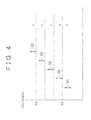
- FIG. 4 is a diagram used for explaining the relation among the minimum operating voltage ranges for the actuators in the embodiment.
- FIG. 4 shows a minimum operating voltage range 52 for the shutoff valves 36 and 37, a minimum operating voltage range 54 for the communication valves 38 and 39, a minimum operating voltage range 56 for the hydraulic pressure adjusting valves 32 to 35, a minimum operating voltage range 58 for the motors 11 and 12, and a minimum operating voltage range 60 for the brake light switch 19.
- the actuators stop operating in the predetermined sequence. More specifically, when the voltage of the power supply decreases, the shutoff valves 36 and 37, the communication valves 38 and 39, the hydraulic pressure adjusting valves 32 to 35, the motors 11 and 12, and the brake light switch 19 stop operating in this stated sequence.
- the minimum operating voltage ranges 52 to 60 for the actuators do not overlap each other.
- the minimum operating voltage range 52 for the shutoff valves 36 and 37 i.e., the second actuator
- the minimum operating voltage range 54 for the communication valves 38 and 39 i.e., the first actuator
- the maximum value in the first minimum operating voltage range for the first actuator is lower than the minimum value in the second minimum operating voltage range for the second actuator.
- the actuators stop operating in the predetermined sequence.
- the actuator that has the minimum operating voltage range (i.e., the second minimum operating voltage range) higher than the first minimum operating voltage range for the first actuator is regarded as the second actuator.
- the brake control in each of stages “a” to “e” will be described on the assumption that the minimum operating voltage for each actuator is equal to the minimum value in the minimum operating voltage range.
- the brake control is executed in a normal manner.
- the normally-open shutoff valves 36 and 37 stop operating, and as a result, communication is provided between the master cylinder 3 and the front-right wheel cylinder 6FR, and between the master cylinder 3 and the front-left wheel cylinder 6FL. Accordingly, the hydraulic pressure is supplied from the master cylinder 3 to the front-right wheel cylinder 6FR and the front-left wheel cylinder 6FL, according to the amount by which the driver depresses the brake pedal 1. Further, the hydraulic pressure adjusting valves 32 to 35 and the communication valves 38, 39 are controllable.
- the brake control system 100 executes the brake control by applying the hydraulic pressures from the master cylinder 3, and applying the hydraulic pressures by operating the motors 11 and 12.
- the brake control system 100 executes the brake control by applying the hydraulic pressures from the master cylinder 3, and applying the hydraulic pressures by operating the motors 11 and 12 according to the output from the brake light switch 19.
- the hydraulic pressure adjusting valves 32 and 35 cannot be used to adjust the wheel cylinder pressures for the front wheels, although the hydraulic pressure adjusting valves 33 and 34 for the rear wheels can be used to adjust the wheel cylinder pressures for the rear wheels.
- the wheel cylinder pressures for the front wheels may be adjusted by adjusting the rotational speeds of the motors 11 and 12.
- the normally-open hydraulic pressure adjusting valves 32 to 35 stop operating.
- the hydraulic pressure adjusting valves 33 and 34 which can be used at the stage “c" cannot be used to adjust the wheel cylinder pressures for the rear wheels at the stage “d”.
- the wheel cylinders for the front wheels are controlled by applying the hydraulic pressures from the master cylinder 3, and applying the hydraulic pressures by operating the motors 11 and 12 according to the output from the brake light switch 19.
- the wheel cylinder pressures for the rear wheels are controlled as follows.
- Target hydraulic pressures are calculated based on the output(s) from the stroke sensor 2 or the hydraulic pressure sensors 17 and 18, the rotational speeds of the motors 11 and 12 are calculated based on the target hydraulic pressures, and the wheel cylinder pressures for the rear wheels are controlled by applying the hydraulic pressures by operating the motors 11 and 12.
- the motors 11 and 12 stop operating.
- the wheel cylinder pressures for the front wheels are controlled by applying the hydraulic pressures from the master cylinder 3.
- the first actuator is the sensor that detects whether the driver is performing the braking operation, for example, the brake light switch 19, and the second actuator includes the motors 11 and 12 that operate the pumps 7 to 10, and the electromagnetically-controlled valves 30 and 32 to 39 that are controlled by controlling the electric current supplied to the electromagnetically-controlled valves 30 and 32 to 39.
- the first actuator When taking into account the relation between the stage “a” and the stage “b", the first actuator includes first electromagnetically-controlled valves that are normally closed, and the second actuator includes second electromagnetically-controlled valves that are normally open.
- the first electromagnetically-controlled valves When the first electromagnetically-controlled valves are closed, the first electromagnetically-controlled valves interrupt the discharge of the operating fluid from the wheel cylinders.
- the second electromagnetically-controlled valves When second electromagnetically-controlled valves are closed, the second electromagnetically-controlled valves interrupt the communication between the master cylinder 3 and the wheel cylinders 6.
- the first actuator includes the communication valves 38 and 39
- the second actuator includes the shutoff valves 36 and 37.
- the brake control system 100 includes two brake systems that are separately controlled.
- the brake control system 100 includes a first brake system that supplies the operating fluid to the front-right wheel cylinder 6FR provided at the front-right wheel FR, and the rear-left wheel cylinder 6RL provided at the rear-left wheel RL; and a second brake system that supplies the operating fluid to the front-left wheel cylinder 6FL provided at the front-left wheel FL, and the rear-right wheel cylinder 6RR provided at the rear-right wheel RR.
- Each of the actuators excluding the brake light switch 19 belongs to one of the first brake system and the second brake system.
- the actuators stop operating in the sequence shown in FIG. 4 , and in addition, the maximum value in the first minimum operating voltage range for the first actuator belonging to the first brake system is lower than the minimum value in the first minimum operating voltage range for the first actuator belonging to the second brake system. Also, in the brake control system 100 according to the embodiment, the maximum value in the second minimum operating voltage range for the second actuator belonging to the first brake system is lower than the minimum value in the second minimum operating voltage range for the second actuator belonging to the second brake system. Thus, the minimum operating voltage for the actuator belonging to the first brake system is lower than the minimum operating voltage for the actuator belonging to the second brake system. Accordingly, it is possible to delay the stop of the operation of the actuator belonging to the first brake system. When the voltage of the power supply decreases, the actuator belonging to one brake system stops operating to decrease power consumption, before the actuator belonging to the other brake system stops operating. As a result, it is possible to delay the stop of the operation of the actuator belonging to the other brake system.
- the first minimum operating voltage range for the first actuator is different from the second minimum operating voltage range for the second actuator.
- the first actuator controls the braking forces applied to the front wheels
- the second actuator controls the braking forces applied to the rear wheels.
- the maximum value in the first minimum operating voltage range for the first actuator for the front wheels is lower than the minimum value in the second minimum operating voltage range for the second actuator for the rear wheels. More specifically, the maximum value in the minimum operating voltage range for the hydraulic pressure adjusting valves 32 and 35 is lower than the minimum value in the minimum operating voltage range for the hydraulic pressure adjusting valves 33 and 34.
- the brake ECU 200 may execute a control that stops the operations of the hydraulic pressure adjusting valves 32 to 35 so that the operations of the actuators are stopped in the sequence shown in FIG. 4 .
- opening degree sensors may be provided at the respective hydraulic pressure adjusting valves 32 to 35, and when it is detected that at least one of the hydraulic pressure adjusting valves 32 to 35 stops operating, the brake ECU 200 may execute a control that stops the operations of the other three hydraulic pressure adjusting valves. Also, the brake ECU 200 may estimate whether at least one of the hydraulic pressure adjusting valves 32 to 35 stops operating, based on values detected by the hydraulic pressure sensors 13 to 16, without using the opening degree sensors. Thus, it is possible to more reliably stop the operations of the actuators in the predetermined sequence. Also, as compared to the case in which the brake ECU 200 executes a control that stops the operations of all the actuators when the voltage of the power supply decreases, the control is simple, and the increase in the cost is suppressed.
- the brake ECU 200 may monitor whether the actuators stop operating in the predetermined sequence when the voltage of the power supply decreases, and if the brake ECU 200 determines that at least one actuator, which should stop operating, is still operating, the brake ECU 200 may execute a control that stops the operation of that at least one actuator.
- the brake ECU 200 can actively perform a control to stop the operations of the shutoff valves 36 and 37 to place the brake control system 100 in the state at the stage "c". If the communication valves 38 and 39 have stopped operating and the shutoff valves 36 and 37 have not stopped operating, the operating fluid for the front wheels is not discharged. Therefore, the brake ECU 200 can determine whether the actuators have stopped operating in an abnormal sequence, by comparing the outputs from the hydraulic pressure sensors 13 and 16 for the front wheels, with the outputs from the hydraulic pressure sensors 14 and 15 for the rear wheels.
- the brake ECU 200 can execute an active control that stops the operation of the second actuator that should stop operating before the first actuator stops operating.
- the brake control system 100 it is possible to reduce the possibility that the actuators stop operating in a sequence different from the predetermined sequence. Accordingly, it is possible to execute a safer brake control.
- the embodiment can be applied not only to the brake control system shown in FIG. 1 , but also to other brake control systems.
Abstract
Description
- This document claims priority to Japanese Application No.
2010-029111, filed on February 02, 2010 - The invention relates to a brake control system that applies braking forces to wheels.
- Recently, electronic brake control systems have been provided in vehicles. The brake control system controls braking forces for wheels so that the optimum braking forces are applied to the vehicle according to a situation in which the vehicle is traveling. In the brake control system, wheel cylinder pressures for the wheels are monitored using pressure sensors, and electromagnetic valves are controlled so that the wheel cylinder pressures are equal to target hydraulic pressures calculated based on the amount by which a driver depresses a brake pedal.
- In the brake control system, pumps are used to increase the hydraulic pressures, and the electromagnetic valves are used to control the hydraulic pressures. The actuators, such as the pumps and the electromagnetic valves, operate using power from a battery that functions as a power supply. Therefore, it is necessary to examine how the brake control system should execute a brake control if a voltage decreases due to a malfunction of the battery.
- Published Japanese Translation of
PCT application No. 10-503446 - In the technology described in Published Japanese Translation of
PCT application No. 10-503446 - The invention provides a brake control system that makes it possible to control actuators in a simple manner when the voltage of a power supply decreases.
- An aspect of the invention relates to a brake control system that includes a power supply portion that supplies a voltage to a plurality of actuators; a first actuator that operates to perform a first function when the first actuator is supplied with a voltage equal to or higher than a first minimum operating voltage from the power supply portion; and a second actuator that operates to perform a second function when the second actuator is supplied with a voltage equal to or higher than a second minimum operating voltage from the power supply portion. The first minimum operating voltage and the second minimum operating voltage are set different from each other by a predetermined value so that the first actuator and the second actuator stop operating in a predetermined sequence with a decrease in the supplied voltage.
- According to the aspect, as the voltage of the power supply decreases, the actuators stop operating in the predetermined sequence, although no particular control is executed. Thus, as compared to the case in which the operations of all the actuators are stopped by a control, it is possible to avoid an increase in the cost involved in the control.
- In the brake control system according to the above-described aspect, the first minimum operating voltage and the second minimum operating voltage may be set different from each other by the predetermined value so that a first minimum operating voltage range does not overlap a second minimum operating voltage range. In this case, the first minimum operating voltage range is a range of variation in the first minimum operating voltage for the first actuator due to manufacturing variance, and the second minimum operating voltage range is a range of variation in the second minimum operating voltage for the second actuator due to manufacturing variance. Thus, even in the case in which there is variation in the minimum operating voltage due to manufacturing variance, as the voltage of the power supply decreases, the actuators stop operating in the predetermined sequence, although no particular active control is executed.
- In the brake control system according to the above-described aspect, a maximum value in the first minimum operating voltage range may be lower than a minimum value in the second minimum operating voltage range. Thus, the first actuator stops operating after the second actuator stops operating.
- In the brake control system according to the above-described aspect, the first actuator may include a sensor that detects whether a driver is performing a braking operation; and the second actuator may include a motor that operates a pump, and an electromagnetically-controlled valve that is controlled by controlling an electric current supplied to the electromagnetically-controlled valve. Thus, with a decrease in the voltage of the power supply, the sensor continues to detect whether the driver is performing the braking operation until a time later than a time at which the motor and the electromagnetically-controlled valve stop operating. Accordingly, it is possible to increase the period during which the motor and the electromagnetically-controlled valve are controlled based on the output from the sensor.
- In the brake control system according to the above-described aspect, the first actuator may include a first electromagnetically-controlled valve that is normally closed, and when the first electromagnetically-controlled valve is closed, the first electromagnetically-controlled valve may interrupt discharge of operating fluid from a wheel cylinder; and the second actuator may include a second electromagnetically-controlled valve that is normally open, and when the second electromagnetically-controlled valve is closed, the second electromagnetically-controlled valve may interrupt communication between a master cylinder and the wheel cylinder. Thus, the first electromagnetically-controlled valve stops operating after the second electromagnetically-controlled valve stops operating. Accordingly, it is possible to avoid the situation in which the first electromagnetically-controlled valve stops operating before the second electromagnetically-controlled valve stops operating, and thus, it is possible to avoid the situation in which the hydraulic pressure in the wheel cylinder cannot be decreased.
- In the brake control system according to the above-described aspect, the first actuator may control a braking force applied to a front wheel; and the second actuator may control a braking force applied to a rear wheel. Thus, the first actuator for the front wheel stops operating after the second actuator for the rear wheel stops operating.
- In the brake control system according to the above-described aspect, the first actuator includes a plurality of first actuators, and at least one of the plurality of first actuators belongs to a first brake system and at least another one of the plurality of first actuators belongs to a second brake system that is separately controlled from the first brake system, and the second actuator includes a plurality of second actuators, and at least one of the plurality of second actuators belongs to the first brake system and at least another one of the plurality of second actuators belongs to the second brake system; a maximum value in the first minimum operating voltage range for the one of the plurality of first actuators belonging to the first brake system may be lower than a minimum value in the first minimum operating voltage range for the another one of the plurality of first actuators belonging to the second brake system; and a maximum value in the second minimum operating voltage range for the one of the plurality of second actuators belonging to the first brake system may be lower than a minimum value in the second minimum operating voltage range for the another one of the plurality of second actuators belonging to the second brake system. Thus, with a decrease in the voltage of the power supply, the actuators belonging to one brake system stop operating before the actuators belonging to the other brake system stop operating.
- According to the above-described aspects of the invention, in the brake control system, it is possible to suppress an increase in the cost, and to control the actuators in a simple manner when the voltage of the power supply decreases.
- As should be apparent, the invention can provide a number of advantageous features and benefits. It is to be understood that, in practicing the invention, embodiments can be constructed to include one or more features or benefits of embodiments disclosed herein, but not include other features or benefits. Accordingly, it is to be understood that the preferred embodiments discussed herein are provided as examples and are not to be construed as limiting, particularly since embodiments can be formed to practice the invention that do not include each of the features of the disclosed examples.
- The features, advantages, and technical and industrial significance of this invention will be described in the following detailed description of example embodiments of the invention with reference to the accompanying drawings, in which like numerals denote like elements, and wherein:
-
FIG. 1 is a schematic diagram showing a configuration of a brake control system according to an embodiment of the invention; -
FIG. 2 is a diagram used for explaining a control that stops the operation of a hydraulic pressure adjusting valve in related art; -
FIG. 3 is a diagram used for explaining a manner in which a hydraulic pressure adjusting valve stops operating in the embodiment; and -
FIG. 4 is a diagram showing a relation among minimum operating voltage ranges for actuators in the embodiment. -
FIG. 1 is a schematic diagram showing a configuration of abrake control system 100 according to an exemplary embodiment of the invention.FIG. 1 shows an example in which thebrake control system 100 according to the embodiment is applied to a vehicle in which hydraulic circuits of a piping system are configured. The piping system can be directed to a piping system for a front-right wheel and a rear-left wheel, and a piping system for a front-left wheel and a rear-right wheel. In the description of the drawings, the same elements are denoted by the same reference numerals, and redundant description thereof will be omitted as appropriate. - As shown in
FIG. 1 , thebrake control system 100 includes a brake pedal 1, astroke sensor 2, amaster cylinder 3, astroke control valve 30, a stroke simulator 4, a brake hydraulicpressure control actuator 5, a wheel cylinder 6FL for a front-left wheel FL (hereinafter, may be referred to as "front-left wheel cylinder 6FL"), a wheel cylinder 6FR for a front-right wheel FR (hereinafter, may be referred to as "front-right wheel cylinder 6FR"), a wheel cylinder 6RL for a rear-left wheel RL (hereinafter, may be referred to as "rear-left wheel cylinder 6RL"), and a wheel cylinder 6RR for a rear-right wheel RR (hereinafter, may be referred to as "rear-right wheel cylinder 6RR"). Hereinafter, when the positions of the wheel cylinders are not particularly distinguished from each other, the wheel cylinder(s) will be referred to as "wheel cylinder(s) 6". Thebrake control system 100 also includes abrake ECU 200. The brake ECU 200 is a control portion that controls portions of thebrake control system 100. In thebrake control system 100, brake fluid is supplied to the wheel cylinders 6 through the hydraulic circuits. Thus, hydraulic pressures (i.e., wheel cylinder pressures) are supplied to the wheel cylinders 6, and braking forces are applied to the wheels due to the hydraulic pressures. Each wheel cylinder 6 may include a corresponding brake disc (not shown) and a corresponding brake caliper (not shown). A unit including the wheel cylinder, the brake disc, and the brake caliper is referred to as "a disc brake unit". - When a driver depresses the brake pedal 1, a pedal stroke, which is the operation amount of the brake pedal 1, is input to the
stroke sensor 2. As a result, thestroke sensor 2 outputs a detection signal corresponding to the pedal stroke. The detection signal is input to thebrake ECU 200, and thebrake ECU 200 detects the pedal stroke of the brake pedal 1. When a driver depresses the brake pedal 1, abrake light switch 19 changes its states between on-state and off-state, thereby thebrake light switch 19 detects whether a driver is performing a brake operation. The detection signal by thebrake light switch 19 is also input to thebrake ECU 200. In this case, thestroke sensor 2 is employed as an operation amount sensor that detects the operation amount of a brake operating member. However, for example, a depression force sensor that detects a depression force applied to the brake pedal 1 may be employed as the operation amount sensor. - The brake pedal 1 is connected to a push rod or the like that transmits the pedal stroke to a
master cylinder 3. When the push rod or the like is pushed, a master cylinder pressure is generated in each of aprimary chamber 3a and asecondary chamber 3b of themaster cylinder 3. - The
master cylinder 3 includes aprimary piston 3c and asecondary piston 3d. Theprimary chamber 3a and thesecondary chamber 3b are formed using theprimary piston 3c and thesecondary piston 3d. Theprimary piston 3c and thesecondary piston 3d receive the elastic force of aspring 3e. Therefore, when the brake pedal 1 is released, each of thepistons spring 3, and thus the brake pedal 1 returns to an initial position. - A pipe passage B is connected to the
primary chamber 3a of themaster cylinder 3, and a pipe passage K is connected to thesecondary chamber 3b of themaster cylinder 3. The pipe passage B and the pipe passage K extend toward the brake hydraulicpressure control actuator 5. - The
master cylinder 3 includes areservoir tank 3f. When the brake pedal 1 is at the initial position, thereservoir tank 3f is connected to theprimary chamber 3a and to thesecondary chamber 3b through respective passages (not shown). Thereservoir tank 3f supplies the brake fluid into themaster cylinder 3. Surplus brake fluid in themaster cylinder 3 is stored in thereservoir tank 3f. Thereservoir tank 3f is connected to pipe passages C and D that extend toward the brake hydraulicpressure control actuator 5. - A stroke simulator 4 is connected to a pipe passage E that is connected to the pipe passage K. The brake fluid flowing from the
secondary chamber 3b is stored in the stroke simulator 4. Thestroke control valve 30 is provided in the pipe passage E. Thestroke control valve 30 is a normally-closed two position valve that opens and closes the pipe passage E, that is, controls the state of the pipe passage E. Thestroke control valve 30 controls the flow of the brake fluid to the stroke simulator 4. - A pipe passage F is provided in the brake hydraulic
pressure control actuator 5. The pipe passage F is connected to the pipe passage K so that thesecondary chamber 3b of themaster cylinder 3 is connected to the wheel cylinder 6FR for the front-right wheel FR. Ashutoff valve 36 is provided in the pipe passage F. Theshutoff valve 36 is a two position valve that is open (to allow the brake fluid to flow) when de-energized, and closed (to interrupt the flow of the brake fluid) when energized. Theshutoff valve 36 opens and closes the pipe passage F, that is, controls the state of the pipe passage F, thereby controlling the supply of the brake fluid to the wheel cylinder 6FR through the pipe passages K and F. - A pipe passage G is provided in the brake hydraulic
pressure control actuator 5. The pipe passage G is connected to the pipe passage B so that theprimary chamber 3a of themaster cylinder 3 is connected to the wheel cylinder 6FL for the front-left wheel FL. Ashutoff valve 37 is provided in the pipe passage G. Theshutoff valve 37 is a two position valve that is open when de-energized, and closed when energized. Theshutoff valve 37 opens and closes the pipe passage G, that is, controls the state of the pipe passage G, thereby controlling the supply of the brake fluid to the wheel cylinder 6FL through the pipe passages B and G. - A pipe passage H and a pipe passage I are provided in the brake hydraulic
pressure control actuator 5. The pipe passage H is connected to a pipe passage C that extends from thereservoir tank 3f. The pipe passage I is connected to a pipe passage D that extends from thereservoir tank 3f. The pipe passage H branches into two pipe passages H1 and H2. The pipe passage H1 is connected to the front-right wheel cylinder 6FR, and the pipe passage H2 is connected to the rear-left wheel cylinder 6RL. The pipe passage I branches into two pipe passages I3 and I4. The pipe passage I3 is connected to the front-left wheel cylinder 6FL, and the pipe passage I4 is connected to the rear-right wheel cylinder 6RR. As described above, the front-right wheel cylinder 6FR and the front-left wheel cylinder 6FL are the wheel cylinder for the front-right wheel FR and the wheel cylinder for the front-left wheel FL, respectively. The rear-left wheel cylinder 6RL and the rear-right wheel cylinder 6RR are the wheel cylinder for the rear-left wheel RL and the wheel cylinder for the rear-right wheel RR, respectively. -
Pumps 7, 8, 9, and 10 are provided in the pipe passages H1, H2, I3, and I4, respectively. Namely, one pump is provided in each of the pipe passages H1, H2, I3, and I4. Each of the pumps 7 to 10 is, for example, a trochoidal pump that does not make much noise. Among the pumps 7 to 10, the two pumps 7 and 8 are operated by a first motor 11, and the twopumps 9 and 10 are operated by asecond motor 12. The first motor 11 and thesecond motor 12 operate the pumps 7 to 10 in accordance with the operation of the brake pedal 1. When the first motor 11 and thesecond motor 12 operate the pumps 7 to 10, the brake fluid is supplied to the wheel cylinders 6 through the pumps 7 to 10. Hereinafter, when the first motor 11 and thesecond motor 12 are not particularly distinguished from each other, the first motor 11 and thesecond motor 12 will be simply referred to as motors. In the embodiment, the four pumps 7 to 10 function as a hydraulic pressure source. The pumps 7 to 10 are provided in the hydraulic circuits. The pumps 7 and 8 supply the brake fluid to the wheel cylinders 6FR, 6RL in accordance with the rotational speed of the first motor 11 connected to the pumps 7 and 8. Thepumps 9 and 10 supply the brake fluid to the wheel cylinders 6FL 6RR in accordance with the rotational speed of thesecond motor 12 connected to thepumps 9 and 10. Namely, two pumps are operated by one motor, and each of the two pumps is connected to one corresponding wheel cylinder. A common battery may supply electric power to the first motor 11 and thesecond motor 12. When the first motor 11 and thesecond motor 12 operate the pumps 7 to 10, the pumps 7 to 10 supply the brake fluid to the wheel cylinders 6, thereby applying the wheel cylinder pressures. - Pipe passages J1, J2, J3, and J4 are connected in parallel to the
pumps 7, 8, 9, and 10, respectively. Acommunication valve 38 and a hydraulicpressure adjusting valve 32 are provided in the pipe passage J1 that is connected in parallel to the pump 7. Thecommunication valve 38 and the hydraulicpressure adjusting valve 32 are connected in series to each other. Thecommunication valve 38 and the hydraulicpressure adjusting valve 32 are arranged such that thecommunication valve 38 is positioned on the side of an intake port of the pump 7 (i.e., thecommunication valve 38 is positioned at a downstream side of the pipe passage J1 in a direction in which the brake fluid flows), and the hydraulicpressure adjusting valve 32 is positioned on the side of a discharge port of the pump 7 (i.e., the hydraulicpressure adjusting valve 32 is positioned at an upstream side of the pipe passage J1 in the direction in which the brake fluid flows). Namely, thecommunication valve 38 allows the brake fluid to flow between thereservoir tank 3f and the hydraulicpressure adjusting valve 32, and interrupts the flow of the brake fluid between thereservoir tank 3f and the hydraulicpressure adjusting valve 32. Thecommunication valve 38 is a two position valve that is closed when de-energized, and open when energized. The hydraulicpressure adjusting valve 32 is a normally-open linear valve which is open when de-energized, and closed when energized, and whose opening degree is adjusted by controlling an electric current supplied to the hydraulicpressure adjusting valve 32. - Forces F1, F2, F3, and F4 act on the hydraulic
pressure adjusting valve 32. F1 represents an electromagnetic driving force corresponding to the electric current supplied to a linear solenoid (not shown) of the hydraulicpressure adjusting valve 32, F2 represents an urging force of a spring (not shown), F3 represents a pressure-difference acting force corresponding to a pressure difference between an inlet and an outlet (not shown) of the hydraulicpressure adjusting valve 32, and F4 represents a frictional force against the sliding of the solenoid. The opening degree of the hydraulicpressure adjusting valve 32 depends on the value of {(F2 + F3 + F4) - F1}. Namely, as the electromagnetic driving force F1 becomes larger, the opening degree of the hydraulicpressure adjusting valve 32 becomes smaller. - Next, a valve-closing current characteristic relating to the hydraulic
pressure adjusting valve 32 will be described. The valve-closing current is the value of the electric current supplied to the hydraulicpressure adjusting valve 32 when the hydraulicpressure adjusting valve 32, which has been open, is to be closed. The valve-closing current characteristic is a characteristic showing the relation between the valve-closing current and the wheel cylinder pressure. The valve-closing current characteristic is expressed by a linear function in which the valve-closing current is linearly proportional to the wheel cylinder pressure. The operating fluid flows out from the front-right wheel cylinder 6FR to the hydraulicpressure adjusting valve 32, and flows from the hydraulicpressure adjusting valve 32 toward thecommunication valve 38 positioned at the downstream side for this out flow. As described above, the hydraulicpressure adjusting valve 32 is a normally-open linear valve. Therefore, as the electric current supplied to the hydraulicpressure adjusting valve 32 increases, the opening degree of the hydraulicpressure adjusting valve 32 decreases, and the flow rate of the hydraulicpressure adjusting valve 32 decreases. When the value of the supplied electric current reaches the valve-closing current, the hydraulicpressure adjusting valve 32 is closed, and the flow rate of the hydraulicpressure adjusting valve 32 is zero. - A hydraulic
pressure adjusting valve 33 is provided in the pipe passage J2 that is connected in parallel to the pump 8. The hydraulicpressure adjusting valve 33 is a linear valve, as is the hydraulicpressure adjusting valve 32. Each of the hydraulicpressure adjusting valves 33 to 35 is a normally-open linear valve, and functions in the same manner in which the hydraulicpressure adjusting valve 32 functions. Hereinafter, when the hydraulicpressure adjusting valves 32 to 35 are not particularly distinguished from each other, the hydraulic pressure adjusting valve(s) may be simply referred to as "the hydraulic pressure adjusting valve(s)". When thecommunication valves - The
communication valve 39 and the hydraulicpressure adjusting valve 35 are provided in the pipe passage J3 that is connected in parallel to the pump 9. Thecommunication valve 39 and the hydraulicpressure adjusting valve 35 are connected in series to each other. Thecommunication valve 39 and the hydraulicpressure adjusting valve 35 are arranged such that thecommunication valve 39 is positioned on the side of an intake port of the pump 9 (i.e., thecommunication valve 39 is positioned at a downstream side of the pipe passage J3 in the direction in which the brake fluid flows), and the hydraulicpressure adjusting valve 35 is positioned on the side of a discharge port of the pump 9 (i.e., the hydraulicpressure adjusting valve 35 is positioned at an upstream side of the pipe passage J3 in the direction in which the brake fluid flows). Namely, thecommunication valve 39 allows the brake fluid to flow between thereservoir tank 3f and the hydraulicpressure adjusting valve 35, and interrupts the flow of the brake fluid between thereservoir tank 3f and the hydraulicpressure adjusting valve 35. Thecommunication valve 39 is a two position valve that is closed when de-energized, and open when energized. The hydraulicpressure adjusting valve 35 is a linear valve that is open when de-energized, and closed when energized, and whose opening degree is adjusted by controlling the electric current supplied to the hydraulicpressure adjusting valve 35. The opening degree of the hydraulicpressure adjusting valve 35 is adjusted by controlling the electric current supplied to the hydraulicpressure adjusting valve 35, and the amount of the brake fluid in the front-left wheel cylinder 6FL is adjusted by adjusting the opening degree of the hydraulicpressure adjusting valve 35. By controlling the electric current supplied to the hydraulic pressure adjusting valve and the communication valve, the opening degrees of the hydraulic pressure adjusting valve and the communication valve are adjusted to control the discharge of the brake fluid from the wheel cylinder 6. - The hydraulic
pressure adjusting valve 34 is provided in the pipe passage J4 that is connected in parallel to thepump 10. The hydraulicpressure adjusting valve 34 is a linear valve, as is the hydraulicpressure adjusting valve 35. - A
hydraulic pressure sensor 13 is disposed in the pipe passage H1 at a position between the pump 7 and the wheel cylinder 6FR. A hydraulic pressure sensor 14 is disposed in the pipe passage H2 at a position between the pump 8 and the wheel cylinder 6RL. Ahydraulic pressure sensor 15 is disposed in the pipe passage I4 at a position between thepump 10 and the wheel cylinder 6RR. Ahydraulic pressure sensor 16 is disposed in the pipe passage I3 at a position between the pump 9 and the wheel cylinder 6FL. Thehydraulic pressure sensor 13 detects the hydraulic pressure in the wheel cylinder 6FR. The hydraulic pressure sensor 14 detects the hydraulic pressure in the wheel cylinder 6RL. Thehydraulic pressure sensor 15 detects the hydraulic pressure in the wheel cylinder 6RR. Thehydraulic pressure sensor 16 detects the hydraulic pressure in the wheel cylinder 6FL. Ahydraulic pressure sensor 17 is disposed in the pipe passage G at a position upstream of the shutoff valve 37 (i.e., at a position between theshutoff valve 37 and the master cylinder 3). Ahydraulic pressure sensor 18 is disposed in the pipe passage F at a position upstream of the shutoff valve 36 (i.e., at a position between theshutoff valve 36 and the master cylinder 3). Thehydraulic pressure sensor 17 detects the master cylinder pressure generated in theprimary chamber 3a of themaster cylinder 3, and thehydraulic pressure sensor 18 detects the master cylinder pressure generated in thesecondary chamber 3b of themaster cylinder 3. - A
check valve 20 is provided at the discharge port of the pump 7 for applying a pressure to the front-right wheel cylinder 6FR. Acheck valve 21 is provided at the discharge port of the pump 9 for applying a pressure to the front-left wheel cylinder 6FL. Thecheck valve 20 is provided to prohibit the flow of the brake fluid from the front-right wheel cylinder 6FR toward the pump 7. Thecheck valve 21 is provided to prohibit the flow of the brake fluid from the front-left wheel cylinder 6FL toward the pump 9. The brake hydraulicpressure control actuator 5 is thus configured. - In the
brake control system 100 with the above-described configuration, a first piping system includes: i) a hydraulic circuit including lines that connect thereservoir tank 3f to the front-right wheel cylinder 6FR and the rear-left wheel cylinder 6RL through the pipe passages C, H, H1, and H2, and lines of the pipe passages J1 and J2 that are connected in parallel to the pumps 7 and 8, respectively; and ii) a hydraulic circuit that connects thesecondary chamber 3b to the front-right wheel cylinder 6FR through the pipe passages K and F. - A second piping system includes: i) a hydraulic circuit including lines that connect the
reservoir tank 3f to the front-left wheel cylinder 6FL and the rear-right wheel cylinder 6RR through the pipe passages D, I, I3, and I4, and lines of the pipe passages J3 and J4 that are connected in parallel to thepumps 9 and 10, respectively; and ii) a hydraulic circuit that connects theprimary chamber 3a to the front-left wheel cylinder 6FL through the pipe passages B and G. - The detection signals output from the
stroke sensor 2 and thehydraulic pressure sensors 13 to 18 are input to thebrake ECU 200. Thebrake ECU 200 outputs control signals for operating thestroke control valve 30, theshutoff valves communication valves pressure adjusting valves 32 to 35, the first motor 11, and thesecond motor 12, based on the pedal stroke, the hydraulic pressures in the wheel cylinders 6, and the master cylinder pressures that are determined based on the detection signals. - Normally, when the brake pedal 1 is depressed, and the detection signals output from the
stroke sensor 2 and thehydraulic pressure sensors brake ECU 200, thebrake ECU 200 controls the electromagnetically-controlledvalves second motors 11 and 12 as follows. Both of theshutoff valves communication valves shutoff valves communication valves - Also, the opening degree of each of the hydraulic
pressure adjusting valves 32 to 35 is adjusted in accordance with the value of the electric current supplied thereto. Thestroke control valve 30 is energized, and therefore, communication is provided between the stroke simulator 4 and thesecondary chamber 3b through the pipe passages K and E. Thus, when the brake pedal 1 is depressed and thepistons secondary chamber 3b to the stroke simulator 4. This prevents the driver from feeling that the brake pedal 1 is stiff due to high master cylinder pressures when the driver depresses the brake pedal 1. - Further, both of the first motor 11 and the
second motor 12 are energized, and the brake fluid flows out from the pumps 7 to 10 to the wheel cylinders 6 without passing through the electromagnetically-controlled valves. Namely, when the pumps 7 to 10 operate, the brake fluid is supplied to the wheel cylinders 6. - The
brake ECU 200 controls the rotational speed of each of the first motor 11 and thesecond motor 12, thereby controlling the amount of the brake fluid supplied to each wheel cylinder 6. Because each of theshutoff valves communication valves pressure adjusting valves 32 to 35 is controlled, the brake fluid is discharged from each wheel cylinder 6 in accordance with the opening degree of the corresponding hydraulicpressure adjusting valve - The
brake ECU 200 monitors the hydraulic pressure supplied to each wheel cylinder 6 based on the detection signal output from each of thehydraulic pressure sensors 13 to 16, and controls the value of the electric current supplied to each of the hydraulicpressure adjusting valves 32 to 35 so that the hydraulic pressure in each wheel cylinder 6 is equal to a desired value. Thus, braking forces are generated in accordance with the pedal stroke of the brake pedal 1. Thebrake control system 100 in the embodiment executes the brake control in the above-described manner. - In the
brake control system 100, the actuators including the pumps 7 to 10, the electromagnetically-controlledvalves motors 11 and 12, and thebrake light switch 19 operate using power from a battery (not shown) that functions as a power supply. Therefore, if a voltage required to operate the actuators cannot be supplied due to a malfunction of the battery, the actuators cannot operate. In this case, it is preferable to maintain the function(s) of the important actuator(s) to execute the brake control to the extent possible. - Accordingly, there has been proposed a method in which priorities are assigned to actuators, and when the voltage of a power supply decreases, the operations of the actuators are stopped in a predetermined sequence according to the voltage of the power supply. However, if the operations of all the actuators are stopped by a control, the control is complicated, and the cost is increased. In addition, if the operation of each of the actuators is stopped by a control, even an actuator that is still operable may be stopped by the control. This situation will be more specifically described with reference to
FIG. 2 . -
FIG. 2 is a diagram used for explaining a control that stops the operation of a hydraulic pressure adjusting valve in related art. InFIG. 2 , the axis of ordinate indicates a voltage, and the axis of abscissa indicates a pressure difference between an inlet and an outlet of a hydraulic pressure adjusting valve. InFIG. 2 , a solid line indicates aminimum operating voltage 44 for the hydraulic pressure adjusting valve, a chain line indicates amaximum value 42 in a minimum operating voltage range for the hydraulic pressure adjusting valve, and a two-dot chain line indicates aminimum value 46 in the minimum operating voltage range for the hydraulic pressure adjusting valve. - The minimum operating voltage is the minimum voltage value at or above which an actuator is operable. If a voltage supplied to the actuator is lower than the minimum operating voltage, the actuator does not operate. Namely, if a voltage equal to or higher than the minimum operating voltage is supplied from a power supply portion to the actuator, the actuator operates, that is, the actuator performs a function. The minimum operating voltage range is a range of variation in the minimum operating voltage due to manufacturing variance. Although each actuator is manufactured so that the actuator is operable at or above a predetermined minimum operating voltage, the minimum operating voltage varies among the manufactured actuators. Thus, the range of variation in the minimum operating voltage is referred to as the minimum operating voltage range. The minimum operating voltage range is empirically set based on the minimum operating voltage set at the time of manufacturing.
- The
minimum operating voltage 44 for the normally-open hydraulic pressure adjusting valve changes in accordance with the pressure-difference acting force corresponding to the pressure difference between the inlet and the outlet of the hydraulic pressure adjusting valve. As shown inFIG. 2 , when the pressure difference between the inlet and the outlet of the hydraulic pressure adjusting valve increases, the pressure-difference acting force acts in such a direction as to open the hydraulic pressure adjusting valve, and therefore, theminimum operating voltage 44 increases. - In the case that the operation of the hydraulic pressure adjusting valve is stopped by a control when the voltage of the power supply decreases, it is necessary to set a stop voltage at which the operation of the actuator should be stopped. In the related art, the stop voltage is set to the
maximum voltage 42 in the minimum operating voltage range, taking into account the minimum operating voltage range. Accordingly, when the voltage supplied to the hydraulic pressure adjusting valve is in aregion 48, that is, when the voltage supplied to the hydraulic pressure adjusting valve is higher than themaximum value 42 in the minimum operating voltage range, the hydraulic pressure adjusting valve operates. - In the related art, although the hydraulic pressure adjusting valve is operable until the voltage decreases to the
minimum operating voltage 44, the operation of the hydraulic pressure adjusting valve is stopped at themaximum value 42 in the minimum operating voltage range. This decreases the robustness against a decrease in the voltage of the power supply. Namely, there is a difference between themaximum value 42 in the minimum operating voltage range, at which the operation of the hydraulic pressure adjusting valve is stopped, and theminimum operating voltage 44 at which the hydraulic pressure adjusting valve is still operable. Thus, the capability of the hydraulic pressure adjusting valve is not used to the fullest extent possible. In contrast, if the operation of the hydraulic pressure adjusting valve is not stopped by the control, the capability of the hydraulic pressure adjusting valve is used to the fullest extent possible. -
FIG. 3 is a diagram used for explaining a manner in which the hydraulic pressure adjusting valve stops operating in the present embodiment. InFIG. 3 , the axis of ordinate indicates the voltage, and the axis of abscissa indicates the pressure difference between the inlet and the outlet of the hydraulic pressure adjusting valve. In thebrake control system 100 according to the embodiment, when the voltage of the power supply decreases, basically, the control that stops the operations of the actuators is not executed. As the voltage of the power supply decreases, the actuators stop operating in a predetermined sequence, although no particular active control is executed. - Accordingly, when the voltage supplied to the hydraulic pressure adjusting valve is in a
region 50, that is, when the voltage supplied to the hydraulic pressure adjusting valve is equal to or higher than theminimum operating voltage 44, the hydraulic pressure adjusting valve operates. Thus, as compared to the related art shown inFIG. 2 , the voltage region in which the hydraulic pressure adjusting valve operates is increased by the difference between themaximum value 42 in the minimum operating voltage range and theminimum operating voltage 44, and thus the robustness is increased. - In the embodiment, a first minimum operating voltage for a first actuator and a second minimum operating voltage for a second actuator are set to be different from each other by a predetermined value so that the first actuator and the second actuator stop operating in a predetermined sequence when the supplied voltage decreases. Also, in the
brake control system 100, a first minimum operating voltage range for the first actuator does not overlap a second minimum operating voltage range for the second actuator so that the first actuator and the second actuator stop operating in the predetermined sequence when the supplied voltage decreases. Namely, the first minimum operating voltage for the first actuator and the second minimum operating voltage for the second actuator are set to be different from each other by the predetermined value so that the first minimum operating voltage range for the first actuator does not overlap the second minimum operating voltage range for the second actuator. Thus, with a decrease in the voltage of the power supply , the actuators stop operating in the predetermined sequence, although no active control that stops the operations of the actuators is executed. The predetermined value by which the first minimum operating voltage is different from the second minimum operating voltage (i.e., the predetermined difference between the first minimum operating voltage and the second minimum operating voltage) is set based on the first minimum operating voltage range for the first actuator and the second minimum operating voltage range for the second actuator. Namely, the predetermined voltage difference is set based on the variation in the first minimum operating voltage due to manufacturing variance, and the variation in the second minimum operating voltage due to manufacturing variance. -
FIG. 4 is a diagram used for explaining the relation among the minimum operating voltage ranges for the actuators in the embodiment.FIG. 4 shows a minimumoperating voltage range 52 for theshutoff valves operating voltage range 54 for thecommunication valves operating voltage range 56 for the hydraulicpressure adjusting valves 32 to 35, a minimumoperating voltage range 58 for themotors 11 and 12, and a minimumoperating voltage range 60 for thebrake light switch 19. Thus, when the voltage of the power supply decreases, the actuators stop operating in the predetermined sequence. More specifically, when the voltage of the power supply decreases, theshutoff valves communication valves pressure adjusting valves 32 to 35, themotors 11 and 12, and thebrake light switch 19 stop operating in this stated sequence. - In the
brake control system 100 according to the embodiment, the minimum operating voltage ranges 52 to 60 for the actuators do not overlap each other. For example, when the minimumoperating voltage range 52 for theshutoff valves 36 and 37 (i.e., the second actuator) is compared with the minimumoperating voltage range 54 for thecommunication valves 38 and 39 (i.e., the first actuator), the maximum value in the first minimum operating voltage range for the first actuator is lower than the minimum value in the second minimum operating voltage range for the second actuator. Thus, with a decrease in the voltage of the power supply, the actuators stop operating in the predetermined sequence. It is to be noted that the actuator that has the minimum operating voltage range (i.e., the second minimum operating voltage range) higher than the first minimum operating voltage range for the first actuator is regarded as the second actuator. - Hereinafter, the brake control in each of stages "a" to "e" will be described on the assumption that the minimum operating voltage for each actuator is equal to the minimum value in the minimum operating voltage range. First, at the stage "a", the brake control is executed in a normal manner.
- Next, at the stage "b", the normally-
open shutoff valves master cylinder 3 and the front-right wheel cylinder 6FR, and between themaster cylinder 3 and the front-left wheel cylinder 6FL. Accordingly, the hydraulic pressure is supplied from themaster cylinder 3 to the front-right wheel cylinder 6FR and the front-left wheel cylinder 6FL, according to the amount by which the driver depresses the brake pedal 1. Further, the hydraulicpressure adjusting valves 32 to 35 and thecommunication valves brake control system 100, the operation performed by the driver is detected using thebrake light switch 19, and then, themotors 11 and 12 are operated according to the detected operation performed by the driver, and the wheel cylinder pressures are adjusted using the hydraulicpressure adjusting valves 32 to 35 and thecommunication valves brake control system 100 executes the brake control by applying the hydraulic pressures from themaster cylinder 3, and applying the hydraulic pressures by operating themotors 11 and 12. - Next, at the stage "c", the normally-closed
communication valves pressure adjusting valves reservoir tank 3f is interrupted. At this stage as well, thebrake control system 100 executes the brake control by applying the hydraulic pressures from themaster cylinder 3, and applying the hydraulic pressures by operating themotors 11 and 12 according to the output from thebrake light switch 19. In the brake control, the hydraulicpressure adjusting valves pressure adjusting valves motors 11 and 12. - Next, at the stage "d", the normally-open hydraulic
pressure adjusting valves 32 to 35 stop operating. Thus, the hydraulicpressure adjusting valves master cylinder 3, and applying the hydraulic pressures by operating themotors 11 and 12 according to the output from thebrake light switch 19. In contrast, the wheel cylinder pressures for the rear wheels are controlled as follows. Target hydraulic pressures are calculated based on the output(s) from thestroke sensor 2 or thehydraulic pressure sensors motors 11 and 12 are calculated based on the target hydraulic pressures, and the wheel cylinder pressures for the rear wheels are controlled by applying the hydraulic pressures by operating themotors 11 and 12. - Next, at the stage "e", the
motors 11 and 12 stop operating. At the stage "e", the wheel cylinder pressures for the front wheels are controlled by applying the hydraulic pressures from themaster cylinder 3. - Because the actuators stop operating in the predetermined sequence as described above, it is possible to increase the period during which the
brake control system 100 continues to execute the brake control when the voltage of the power supply decreases. - When taking into account the relation between the stages "a" to "d" and the stage "e", the first actuator is the sensor that detects whether the driver is performing the braking operation, for example, the
brake light switch 19, and the second actuator includes themotors 11 and 12 that operate the pumps 7 to 10, and the electromagnetically-controlledvalves valves brake light switch 19 to detect the operation performed by the driver, until the end of the brake control. Thus, it is possible to increase the period during which thebrake control system 100 continues to execute the brake control by operating themotors 11 and 12 according to the operation performed by the driver, with a decrease in the voltage of the power supply. - When taking into account the relation between the stage "a" and the stage "b", the first actuator includes first electromagnetically-controlled valves that are normally closed, and the second actuator includes second electromagnetically-controlled valves that are normally open. When the first electromagnetically-controlled valves are closed, the first electromagnetically-controlled valves interrupt the discharge of the operating fluid from the wheel cylinders. When second electromagnetically-controlled valves are closed, the second electromagnetically-controlled valves interrupt the communication between the
master cylinder 3 and the wheel cylinders 6. Namely, the first actuator includes thecommunication valves shutoff valves communication valves shutoff valves communication valves shutoff valves - As shown in
FIG. 1 , thebrake control system 100 includes two brake systems that are separately controlled. For example, thebrake control system 100 includes a first brake system that supplies the operating fluid to the front-right wheel cylinder 6FR provided at the front-right wheel FR, and the rear-left wheel cylinder 6RL provided at the rear-left wheel RL; and a second brake system that supplies the operating fluid to the front-left wheel cylinder 6FL provided at the front-left wheel FL, and the rear-right wheel cylinder 6RR provided at the rear-right wheel RR. Each of the actuators excluding thebrake light switch 19 belongs to one of the first brake system and the second brake system. - Accordingly, in the
brake control system 100 according to the embodiment, the actuators stop operating in the sequence shown inFIG. 4 , and in addition, the maximum value in the first minimum operating voltage range for the first actuator belonging to the first brake system is lower than the minimum value in the first minimum operating voltage range for the first actuator belonging to the second brake system. Also, in thebrake control system 100 according to the embodiment, the maximum value in the second minimum operating voltage range for the second actuator belonging to the first brake system is lower than the minimum value in the second minimum operating voltage range for the second actuator belonging to the second brake system. Thus, the minimum operating voltage for the actuator belonging to the first brake system is lower than the minimum operating voltage for the actuator belonging to the second brake system. Accordingly, it is possible to delay the stop of the operation of the actuator belonging to the first brake system. When the voltage of the power supply decreases, the actuator belonging to one brake system stops operating to decrease power consumption, before the actuator belonging to the other brake system stops operating. As a result, it is possible to delay the stop of the operation of the actuator belonging to the other brake system. - Next, a modified example of the
brake control system 100 according to the embodiment will be described. In thebrake control system 100, the first minimum operating voltage range for the first actuator is different from the second minimum operating voltage range for the second actuator. The first actuator controls the braking forces applied to the front wheels, and the second actuator controls the braking forces applied to the rear wheels. The maximum value in the first minimum operating voltage range for the first actuator for the front wheels is lower than the minimum value in the second minimum operating voltage range for the second actuator for the rear wheels. More specifically, the maximum value in the minimum operating voltage range for the hydraulicpressure adjusting valves pressure adjusting valves brake control system 100 continues to execute the brake control for the front wheels. - Even when the minimum operating voltage is set as described above, there is a possibility that the actuators may not stop operating in the predetermined sequence due to disturbance such as a temperature change, with a decrease in the voltage of the power supply. For example, the minimum operating voltage for the hydraulic
pressure adjusting valves 32 to 35 may greatly change due to a temperature change. Therefore, thebrake ECU 200 may execute a control that stops the operations of the hydraulicpressure adjusting valves 32 to 35 so that the operations of the actuators are stopped in the sequence shown inFIG. 4 . For example, opening degree sensors (not shown) may be provided at the respective hydraulicpressure adjusting valves 32 to 35, and when it is detected that at least one of the hydraulicpressure adjusting valves 32 to 35 stops operating, thebrake ECU 200 may execute a control that stops the operations of the other three hydraulic pressure adjusting valves. Also, thebrake ECU 200 may estimate whether at least one of the hydraulicpressure adjusting valves 32 to 35 stops operating, based on values detected by thehydraulic pressure sensors 13 to 16, without using the opening degree sensors. Thus, it is possible to more reliably stop the operations of the actuators in the predetermined sequence. Also, as compared to the case in which thebrake ECU 200 executes a control that stops the operations of all the actuators when the voltage of the power supply decreases, the control is simple, and the increase in the cost is suppressed. - The
brake ECU 200 may monitor whether the actuators stop operating in the predetermined sequence when the voltage of the power supply decreases, and if thebrake ECU 200 determines that at least one actuator, which should stop operating, is still operating, thebrake ECU 200 may execute a control that stops the operation of that at least one actuator. - More specifically, if the
communication valves 38 and 39 (i.e., the first actuator) have stopped operating and theshutoff valves 36 and 37 (i.e., the second actuator) have not stopped operating, the actuators have stopped operating in a sequence different from the predetermined sequence shown inFIG. 4 . Therefore, thebrake ECU 200 can actively perform a control to stop the operations of theshutoff valves brake control system 100 in the state at the stage "c". If thecommunication valves shutoff valves brake ECU 200 can determine whether the actuators have stopped operating in an abnormal sequence, by comparing the outputs from thehydraulic pressure sensors hydraulic pressure sensors 14 and 15 for the rear wheels. - If the
brake ECU 200 cannot determine whether the first actuator has stopped operating, thebrake ECU 200 can execute an active control that stops the operation of the second actuator that should stop operating before the first actuator stops operating. Thus, in thebrake control system 100, it is possible to reduce the possibility that the actuators stop operating in a sequence different from the predetermined sequence. Accordingly, it is possible to execute a safer brake control. - The embodiment can be applied not only to the brake control system shown in
FIG. 1 , but also to other brake control systems. - While the exemplary embodiments have been described, it is to be understood that the invention is not limited to the exemplary embodiments or constructions. To the contrary, the invention is intended to cover various modifications and equivalent arrangements. In addition, while the various elements of the exemplary embodiments are shown in various combinations and configurations, which are exemplary, other combinations and configurations, including more, less, or only a single element, are also within the spirit and scope of the invention.
- Obviously, numerous modifications and variations of the present invention are possible in light of the above teachings. It is therefore to be understood that within the scope of the appended claims, the invention may be practiced otherwise than as specifically described herein.
Claims (7)
- A brake control system comprising:means for supplying a voltage to a plurality of actuators;first means for actuating that operates to perform a first function when the first means for actuating is supplied with a voltage equal to or higher than a first minimum operating voltage from the means for supplying; andsecond means for actuating that operates to perform a second function when the second means for actuating is supplied with a voltage equal to or higher than a second minimum operating voltage from the means for supplying, whereinthe first minimum operating voltage and the second minimum operating voltage are set different from each other by a predetermined value so that the first actuator and the second actuator stop operating in a predetermined sequence with a decrease in the supplied voltage.
- The brake control system according to claim 1, wherein
the first minimum operating voltage and the second minimum operating voltage are set different from each other by the predetermined value so that a first minimum operating voltage range does not overlap a second minimum operating voltage range; and
the first minimum operating voltage range is a range of variation in the first minimum operating voltage for the first means for actuating due to manufacturing variance, and the second minimum operating voltage range is a range of variation in the second minimum operating voltage for the second means for actuating due to manufacturing variance. - The brake control system according to claim 2, wherein
a maximum value in the first minimum operating voltage range is lower than a minimum value in the second minimum operating voltage range. - The brake control system according to any one of claims 1 to 3, wherein
the first means for actuating includes a sensor that detects whether a driver is performing a braking operation; and
the second means for actuating includes a motor that operates a pump, and an electromagnetically-controlled valve that is controlled by controlling an electric current supplied to the electromagnetically-controlled valve. - The brake control system according to any one of claims 1 to 3, wherein
the first means for actuating includes a first electromagnetically-controlled valve that is normally closed, and when the first electromagnetically-controlled valve is closed, the first electromagnetically-controlled valve interrupts discharge of operating fluid from a wheel cylinder; and
the second means for actuating includes a second electromagnetically-controlled valve that is normally open, and when the second electromagnetically-controlled valve is closed, the second electromagnetically-controlled valve interrupts communication between a master cylinder and the wheel cylinder. - The brake control system according to any one of claims 1 to 3, wherein
the first means for actuating controls a braking force applied to a front wheel; and
the second means for actuating controls a braking force applied to a rear wheel. - The brake control system according to claim 2 or 3, wherein
the first means for actuating includes a plurality of first means for actuating, and at least one of the plurality of first means for actuating belongs to a first brake system and at least another one of the plurality of first means for actuating belongs to a second brake system that is separately controlled from the first brake system, and the second means for actuating includes a plurality of second means for actuating, and at least one of the plurality of second means for actuating belongs to the first brake system and at least another one of the plurality of second means for actuating belongs to the second brake system;
a maximum value in the first minimum operating voltage range for the one of the plurality of first means for actuating belonging to the first brake system is lower than a minimum value in the first minimum operating voltage range for the another one of the plurality of first means for actuating belonging to the second brake system; and
a maximum value in the second minimum operating voltage range for the one of the plurality of second means for actuating belonging to the first brake system is lower than a minimum value in the second minimum operating voltage range for the another one of the plurality of second means for actuating belonging to the second brake system.
Applications Claiming Priority (2)
| Application Number | Priority Date | Filing Date | Title |
|---|---|---|---|
| JP2010029111A JP5567854B2 (en) | 2010-02-12 | 2010-02-12 | Brake control device |
| EP11713866.9A EP2534022B1 (en) | 2010-02-12 | 2011-02-04 | Brake control system |
Related Parent Applications (2)
| Application Number | Title | Priority Date | Filing Date |
|---|---|---|---|
| EP11713866.9 Division | 2011-02-04 | ||
| EP11713866.9A Division EP2534022B1 (en) | 2010-02-12 | 2011-02-04 | Brake control system |
Publications (2)
| Publication Number | Publication Date |
|---|---|
| EP2650182A1 true EP2650182A1 (en) | 2013-10-16 |
| EP2650182B1 EP2650182B1 (en) | 2014-10-22 |
Family
ID=44212082
Family Applications (2)
| Application Number | Title | Priority Date | Filing Date |
|---|---|---|---|
| EP11713866.9A Not-in-force EP2534022B1 (en) | 2010-02-12 | 2011-02-04 | Brake control system |
| EP13175609.0A Not-in-force EP2650182B1 (en) | 2010-02-12 | 2011-02-04 | Brake control system |
Family Applications Before (1)
| Application Number | Title | Priority Date | Filing Date |
|---|---|---|---|
| EP11713866.9A Not-in-force EP2534022B1 (en) | 2010-02-12 | 2011-02-04 | Brake control system |
Country Status (5)
| Country | Link |
|---|---|
| US (1) | US9238454B2 (en) |
| EP (2) | EP2534022B1 (en) |
| JP (1) | JP5567854B2 (en) |
| CN (1) | CN102770317B (en) |
| WO (1) | WO2011098877A1 (en) |
Families Citing this family (5)
| Publication number | Priority date | Publication date | Assignee | Title |
|---|---|---|---|---|
| DE102005049300A1 (en) * | 2005-10-12 | 2007-04-26 | Continental Teves Ag & Co. Ohg | Method for determining the wheel pressure in an electronically controllable motor vehicle brake control system |
| DE102012202467A1 (en) * | 2012-02-17 | 2013-08-22 | Continental Teves Ag & Co. Ohg | Method for controlling a brake system, brake system and use |
| DE102016210382A1 (en) * | 2016-06-13 | 2017-12-14 | Robert Bosch Gmbh | Method for operating a vehicle control system |
| JP6750535B2 (en) * | 2017-02-27 | 2020-09-02 | 株式会社アドヴィックス | Vehicle braking control device |
| JP7107148B2 (en) * | 2018-10-03 | 2022-07-27 | トヨタ自動車株式会社 | Actuator control device, in-vehicle system |
Citations (5)
| Publication number | Priority date | Publication date | Assignee | Title |
|---|---|---|---|---|
| JPH10503446A (en) | 1994-04-29 | 1998-03-31 | アイティーティー・オートモーティブ・ヨーロップ・ゲーエムベーハー | Circuit for a braking device with electrical distribution control of braking force |
| EP1013529A2 (en) * | 1998-12-21 | 2000-06-28 | Toyota Jidosha Kabushiki Kaisha | Device for controlling brake system of vehicle with care for battery |
| DE19961469A1 (en) * | 1998-12-21 | 2000-07-06 | Toyota Motor Co Ltd | Arrangement for controlling vehicle braking system with battery checking measures battery voltage in period when fluid is fed to wheel cylinder for zero vehicle speed, no pedal depression |
| DE10354279A1 (en) * | 2002-12-06 | 2004-07-15 | Hitachi, Ltd. | Electric power device used in motor vehicle, has power controller to limit load current if power supply voltage determined based on battery and load conditions, is less than predetermined value |
| WO2006032658A1 (en) * | 2004-09-24 | 2006-03-30 | Continental Teves Ag & Co. Ohg | Method and device for supporting a brake system in case of reduced effectiveness of the vehicle brake system |
Family Cites Families (10)
| Publication number | Priority date | Publication date | Assignee | Title |
|---|---|---|---|---|
| US5795036A (en) | 1995-05-26 | 1998-08-18 | Campagnolo S.R.L. | Bicycle rear wheel |
| US6692088B1 (en) * | 2001-07-31 | 2004-02-17 | Kelsey-Hayes Company | Boundary self-adaptation scheme for proportional poppet valve pressure control |
| JP4552720B2 (en) * | 2005-03-25 | 2010-09-29 | 株式会社アドヴィックス | Brake hydraulic pressure control device for vehicles |
| DE102005041556A1 (en) * | 2005-09-01 | 2007-03-08 | Continental Teves Ag & Co. Ohg | Method for determining an admission pressure in a motor vehicle brake system |
| JP2007203892A (en) * | 2006-02-02 | 2007-08-16 | Hitachi Ltd | Brake fluid pressure control device |
| JP5119646B2 (en) * | 2006-03-06 | 2013-01-16 | 株式会社アドヴィックス | Brake control device for vehicle |
| JP2007253834A (en) * | 2006-03-24 | 2007-10-04 | Hitachi Ltd | Braking system |
| FR2920356B1 (en) * | 2007-09-04 | 2012-05-18 | Alstom Transport Sa | SECURITY DEVICE FOR DETECTING INSUFFICIENT ELECTRIC BRAKING AND SWITCHING ON A SAFE BRAKE. |
| US8214121B2 (en) * | 2008-03-19 | 2012-07-03 | Goodrich Corporation | Brake control interlock logic |
| JP5135100B2 (en) * | 2008-07-24 | 2013-01-30 | 本田技研工業株式会社 | Vehicle motion control system |
-
2010
- 2010-02-12 JP JP2010029111A patent/JP5567854B2/en not_active Expired - Fee Related
-
2011
- 2011-02-04 US US13/578,734 patent/US9238454B2/en not_active Expired - Fee Related
- 2011-02-04 EP EP11713866.9A patent/EP2534022B1/en not_active Not-in-force
- 2011-02-04 EP EP13175609.0A patent/EP2650182B1/en not_active Not-in-force
- 2011-02-04 WO PCT/IB2011/000186 patent/WO2011098877A1/en active Application Filing
- 2011-02-04 CN CN201180009427.2A patent/CN102770317B/en not_active Expired - Fee Related
Patent Citations (7)
| Publication number | Priority date | Publication date | Assignee | Title |
|---|---|---|---|---|
| JPH10503446A (en) | 1994-04-29 | 1998-03-31 | アイティーティー・オートモーティブ・ヨーロップ・ゲーエムベーハー | Circuit for a braking device with electrical distribution control of braking force |
| US5795039A (en) * | 1994-04-29 | 1998-08-18 | Itt Automotive Europe Gmbh | Brake system which maintains brake force distribution upon system malfunction while partially disabling anti-lock and traction slip |
| EP1013529A2 (en) * | 1998-12-21 | 2000-06-28 | Toyota Jidosha Kabushiki Kaisha | Device for controlling brake system of vehicle with care for battery |
| DE19961469A1 (en) * | 1998-12-21 | 2000-07-06 | Toyota Motor Co Ltd | Arrangement for controlling vehicle braking system with battery checking measures battery voltage in period when fluid is fed to wheel cylinder for zero vehicle speed, no pedal depression |
| DE10354279A1 (en) * | 2002-12-06 | 2004-07-15 | Hitachi, Ltd. | Electric power device used in motor vehicle, has power controller to limit load current if power supply voltage determined based on battery and load conditions, is less than predetermined value |
| US20050063117A1 (en) * | 2002-12-06 | 2005-03-24 | Hitachi, Ltd. | Power supply system |
| WO2006032658A1 (en) * | 2004-09-24 | 2006-03-30 | Continental Teves Ag & Co. Ohg | Method and device for supporting a brake system in case of reduced effectiveness of the vehicle brake system |
Also Published As
| Publication number | Publication date |
|---|---|
| US20120319462A1 (en) | 2012-12-20 |
| EP2534022B1 (en) | 2013-08-28 |
| CN102770317A (en) | 2012-11-07 |
| EP2650182B1 (en) | 2014-10-22 |
| JP2011162123A (en) | 2011-08-25 |
| EP2534022A1 (en) | 2012-12-19 |
| US9238454B2 (en) | 2016-01-19 |
| CN102770317B (en) | 2016-03-02 |
| JP5567854B2 (en) | 2014-08-06 |
| WO2011098877A1 (en) | 2011-08-18 |
Similar Documents
| Publication | Publication Date | Title |
|---|---|---|
| EP2117896B1 (en) | Brake control apparatus and brake control method | |
| JP6432942B2 (en) | Brake device | |
| WO2018003539A1 (en) | Brake device and method for detecting fluid leakage in brake device | |
| EP1777132A2 (en) | Brake control system and brake control method | |
| US20110006593A1 (en) | Brake control apparatus | |
| US8544963B2 (en) | Braking control apparatus | |
| US9517759B2 (en) | Vehicle brake control device | |
| US20180194332A1 (en) | Brake Control Apparatus and Brake System | |
| EP2650182B1 (en) | Brake control system | |
| WO2021106924A1 (en) | Brake control device | |
| WO2017068968A1 (en) | Brake control device | |
| CN109552286B (en) | Brake control device | |
| WO2019230547A1 (en) | Brake control device and method for detecting malfunction in brake control device | |
| JP2009107437A (en) | Brake control device and brake control method | |
| US20220324426A1 (en) | Vehicle braking device | |
| JP5977691B2 (en) | Brake control device | |
| WO2021187435A1 (en) | Vehicle braking device | |
| JP5293418B2 (en) | Brake abnormality detection device | |
| JP2011168079A (en) | Brake device | |
| JP2013082252A (en) | Failure determining device of stop lamp switch | |
| JP2018043613A (en) | Brake control device and method for controlling brake device | |
| JP2011255864A (en) | Brake control device | |
| JP2015024711A (en) | Vehicular hydraulic pressure brake apparatus |
Legal Events
| Date | Code | Title | Description |
|---|---|---|---|
| PUAI | Public reference made under article 153(3) epc to a published international application that has entered the european phase |
Free format text: ORIGINAL CODE: 0009012 |
|
| 17P | Request for examination filed |
Effective date: 20130708 |
|
| AC | Divisional application: reference to earlier application |
Ref document number: 2534022 Country of ref document: EP Kind code of ref document: P |
|
| AK | Designated contracting states |
Kind code of ref document: A1 Designated state(s): AL AT BE BG CH CY CZ DE DK EE ES FI FR GB GR HR HU IE IS IT LI LT LU LV MC MK MT NL NO PL PT RO RS SE SI SK SM TR |
|
| GRAP | Despatch of communication of intention to grant a patent |
Free format text: ORIGINAL CODE: EPIDOSNIGR1 |
|
| INTG | Intention to grant announced |
Effective date: 20140306 |
|
| GRAS | Grant fee paid |
Free format text: ORIGINAL CODE: EPIDOSNIGR3 |
|
| RIN1 | Information on inventor provided before grant (corrected) |
Inventor name: AKITA, KUMIKO Inventor name: YAMAMOTO, TAKAYUKI Inventor name: WATANABE, KOJI Inventor name: URAOKA, TERUSHIGE Inventor name: MIYAZAKI, TETSUYA |
|
| GRAA | (expected) grant |
Free format text: ORIGINAL CODE: 0009210 |
|
| RAP1 | Party data changed (applicant data changed or rights of an application transferred) |
Owner name: ADVICS CO., LTD. Owner name: TOYOTA JIDOSHA KABUSHIKI KAISHA |
|
| AC | Divisional application: reference to earlier application |
Ref document number: 2534022 Country of ref document: EP Kind code of ref document: P |
|
| AK | Designated contracting states |
Kind code of ref document: B1 Designated state(s): AL AT BE BG CH CY CZ DE DK EE ES FI FR GB GR HR HU IE IS IT LI LT LU LV MC MK MT NL NO PL PT RO RS SE SI SK SM TR |
|
| REG | Reference to a national code |
Ref country code: GB Ref legal event code: FG4D |
|
| REG | Reference to a national code |
Ref country code: CH Ref legal event code: EP |
|
| REG | Reference to a national code |
Ref country code: AT Ref legal event code: REF Ref document number: 692471 Country of ref document: AT Kind code of ref document: T Effective date: 20141115 |
|
| REG | Reference to a national code |
Ref country code: IE Ref legal event code: FG4D |
|
| REG | Reference to a national code |
Ref country code: DE Ref legal event code: R096 Ref document number: 602011010864 Country of ref document: DE Effective date: 20141204 |
|
| REG | Reference to a national code |
Ref country code: NL Ref legal event code: VDEP Effective date: 20141022 |
|
| REG | Reference to a national code |
Ref country code: AT Ref legal event code: MK05 Ref document number: 692471 Country of ref document: AT Kind code of ref document: T Effective date: 20141022 |
|
| REG | Reference to a national code |
Ref country code: LT Ref legal event code: MG4D |
|
| PG25 | Lapsed in a contracting state [announced via postgrant information from national office to epo] |
Ref country code: LT Free format text: LAPSE BECAUSE OF FAILURE TO SUBMIT A TRANSLATION OF THE DESCRIPTION OR TO PAY THE FEE WITHIN THE PRESCRIBED TIME-LIMIT Effective date: 20141022 Ref country code: NL Free format text: LAPSE BECAUSE OF FAILURE TO SUBMIT A TRANSLATION OF THE DESCRIPTION OR TO PAY THE FEE WITHIN THE PRESCRIBED TIME-LIMIT Effective date: 20141022 Ref country code: PT Free format text: LAPSE BECAUSE OF FAILURE TO SUBMIT A TRANSLATION OF THE DESCRIPTION OR TO PAY THE FEE WITHIN THE PRESCRIBED TIME-LIMIT Effective date: 20150223 Ref country code: IS Free format text: LAPSE BECAUSE OF FAILURE TO SUBMIT A TRANSLATION OF THE DESCRIPTION OR TO PAY THE FEE WITHIN THE PRESCRIBED TIME-LIMIT Effective date: 20150222 Ref country code: NO Free format text: LAPSE BECAUSE OF FAILURE TO SUBMIT A TRANSLATION OF THE DESCRIPTION OR TO PAY THE FEE WITHIN THE PRESCRIBED TIME-LIMIT Effective date: 20150122 Ref country code: ES Free format text: LAPSE BECAUSE OF FAILURE TO SUBMIT A TRANSLATION OF THE DESCRIPTION OR TO PAY THE FEE WITHIN THE PRESCRIBED TIME-LIMIT Effective date: 20141022 Ref country code: FI Free format text: LAPSE BECAUSE OF FAILURE TO SUBMIT A TRANSLATION OF THE DESCRIPTION OR TO PAY THE FEE WITHIN THE PRESCRIBED TIME-LIMIT Effective date: 20141022 |
|
| PG25 | Lapsed in a contracting state [announced via postgrant information from national office to epo] |
Ref country code: AT Free format text: LAPSE BECAUSE OF FAILURE TO SUBMIT A TRANSLATION OF THE DESCRIPTION OR TO PAY THE FEE WITHIN THE PRESCRIBED TIME-LIMIT Effective date: 20141022 Ref country code: CY Free format text: LAPSE BECAUSE OF FAILURE TO SUBMIT A TRANSLATION OF THE DESCRIPTION OR TO PAY THE FEE WITHIN THE PRESCRIBED TIME-LIMIT Effective date: 20141022 Ref country code: RS Free format text: LAPSE BECAUSE OF FAILURE TO SUBMIT A TRANSLATION OF THE DESCRIPTION OR TO PAY THE FEE WITHIN THE PRESCRIBED TIME-LIMIT Effective date: 20141022 Ref country code: HR Free format text: LAPSE BECAUSE OF FAILURE TO SUBMIT A TRANSLATION OF THE DESCRIPTION OR TO PAY THE FEE WITHIN THE PRESCRIBED TIME-LIMIT Effective date: 20141022 Ref country code: LV Free format text: LAPSE BECAUSE OF FAILURE TO SUBMIT A TRANSLATION OF THE DESCRIPTION OR TO PAY THE FEE WITHIN THE PRESCRIBED TIME-LIMIT Effective date: 20141022 Ref country code: GR Free format text: LAPSE BECAUSE OF FAILURE TO SUBMIT A TRANSLATION OF THE DESCRIPTION OR TO PAY THE FEE WITHIN THE PRESCRIBED TIME-LIMIT Effective date: 20150123 Ref country code: PL Free format text: LAPSE BECAUSE OF FAILURE TO SUBMIT A TRANSLATION OF THE DESCRIPTION OR TO PAY THE FEE WITHIN THE PRESCRIBED TIME-LIMIT Effective date: 20141022 Ref country code: SE Free format text: LAPSE BECAUSE OF FAILURE TO SUBMIT A TRANSLATION OF THE DESCRIPTION OR TO PAY THE FEE WITHIN THE PRESCRIBED TIME-LIMIT Effective date: 20141022 |
|
| REG | Reference to a national code |
Ref country code: DE Ref legal event code: R097 Ref document number: 602011010864 Country of ref document: DE |
|
| PG25 | Lapsed in a contracting state [announced via postgrant information from national office to epo] |
Ref country code: SK Free format text: LAPSE BECAUSE OF FAILURE TO SUBMIT A TRANSLATION OF THE DESCRIPTION OR TO PAY THE FEE WITHIN THE PRESCRIBED TIME-LIMIT Effective date: 20141022 Ref country code: EE Free format text: LAPSE BECAUSE OF FAILURE TO SUBMIT A TRANSLATION OF THE DESCRIPTION OR TO PAY THE FEE WITHIN THE PRESCRIBED TIME-LIMIT Effective date: 20141022 Ref country code: RO Free format text: LAPSE BECAUSE OF FAILURE TO SUBMIT A TRANSLATION OF THE DESCRIPTION OR TO PAY THE FEE WITHIN THE PRESCRIBED TIME-LIMIT Effective date: 20141022 Ref country code: CZ Free format text: LAPSE BECAUSE OF FAILURE TO SUBMIT A TRANSLATION OF THE DESCRIPTION OR TO PAY THE FEE WITHIN THE PRESCRIBED TIME-LIMIT Effective date: 20141022 Ref country code: DK Free format text: LAPSE BECAUSE OF FAILURE TO SUBMIT A TRANSLATION OF THE DESCRIPTION OR TO PAY THE FEE WITHIN THE PRESCRIBED TIME-LIMIT Effective date: 20141022 |
|
| PLBE | No opposition filed within time limit |
Free format text: ORIGINAL CODE: 0009261 |
|
| STAA | Information on the status of an ep patent application or granted ep patent |
Free format text: STATUS: NO OPPOSITION FILED WITHIN TIME LIMIT |
|
| PG25 | Lapsed in a contracting state [announced via postgrant information from national office to epo] |
Ref country code: IT Free format text: LAPSE BECAUSE OF FAILURE TO SUBMIT A TRANSLATION OF THE DESCRIPTION OR TO PAY THE FEE WITHIN THE PRESCRIBED TIME-LIMIT Effective date: 20141022 |
|
| 26N | No opposition filed |
Effective date: 20150723 |
|
| PG25 | Lapsed in a contracting state [announced via postgrant information from national office to epo] |
Ref country code: LU Free format text: LAPSE BECAUSE OF FAILURE TO SUBMIT A TRANSLATION OF THE DESCRIPTION OR TO PAY THE FEE WITHIN THE PRESCRIBED TIME-LIMIT Effective date: 20150204 |
|
| REG | Reference to a national code |
Ref country code: CH Ref legal event code: PL |
|
| PG25 | Lapsed in a contracting state [announced via postgrant information from national office to epo] |
Ref country code: LI Free format text: LAPSE BECAUSE OF NON-PAYMENT OF DUE FEES Effective date: 20150228 Ref country code: CH Free format text: LAPSE BECAUSE OF NON-PAYMENT OF DUE FEES Effective date: 20150228 Ref country code: MC Free format text: LAPSE BECAUSE OF FAILURE TO SUBMIT A TRANSLATION OF THE DESCRIPTION OR TO PAY THE FEE WITHIN THE PRESCRIBED TIME-LIMIT Effective date: 20141022 |
|
| REG | Reference to a national code |
Ref country code: IE Ref legal event code: MM4A |
|
| REG | Reference to a national code |
Ref country code: DE Ref legal event code: R084 Ref document number: 602011010864 Country of ref document: DE |
|
| REG | Reference to a national code |
Ref country code: GB Ref legal event code: 746 Effective date: 20151124 |
|
| REG | Reference to a national code |
Ref country code: FR Ref legal event code: PLFP Year of fee payment: 6 |
|
| PG25 | Lapsed in a contracting state [announced via postgrant information from national office to epo] |
Ref country code: IE Free format text: LAPSE BECAUSE OF NON-PAYMENT OF DUE FEES Effective date: 20150204 |
|
| PG25 | Lapsed in a contracting state [announced via postgrant information from national office to epo] |
Ref country code: SI Free format text: LAPSE BECAUSE OF FAILURE TO SUBMIT A TRANSLATION OF THE DESCRIPTION OR TO PAY THE FEE WITHIN THE PRESCRIBED TIME-LIMIT Effective date: 20141022 |
|
| PG25 | Lapsed in a contracting state [announced via postgrant information from national office to epo] |
Ref country code: MT Free format text: LAPSE BECAUSE OF FAILURE TO SUBMIT A TRANSLATION OF THE DESCRIPTION OR TO PAY THE FEE WITHIN THE PRESCRIBED TIME-LIMIT Effective date: 20141022 |
|
| REG | Reference to a national code |
Ref country code: FR Ref legal event code: PLFP Year of fee payment: 7 |
|
| PG25 | Lapsed in a contracting state [announced via postgrant information from national office to epo] |
Ref country code: HU Free format text: LAPSE BECAUSE OF FAILURE TO SUBMIT A TRANSLATION OF THE DESCRIPTION OR TO PAY THE FEE WITHIN THE PRESCRIBED TIME-LIMIT; INVALID AB INITIO Effective date: 20110204 Ref country code: SM Free format text: LAPSE BECAUSE OF FAILURE TO SUBMIT A TRANSLATION OF THE DESCRIPTION OR TO PAY THE FEE WITHIN THE PRESCRIBED TIME-LIMIT Effective date: 20141022 Ref country code: BG Free format text: LAPSE BECAUSE OF FAILURE TO SUBMIT A TRANSLATION OF THE DESCRIPTION OR TO PAY THE FEE WITHIN THE PRESCRIBED TIME-LIMIT Effective date: 20141022 |
|
| PG25 | Lapsed in a contracting state [announced via postgrant information from national office to epo] |
Ref country code: TR Free format text: LAPSE BECAUSE OF FAILURE TO SUBMIT A TRANSLATION OF THE DESCRIPTION OR TO PAY THE FEE WITHIN THE PRESCRIBED TIME-LIMIT Effective date: 20141022 |
|
| PG25 | Lapsed in a contracting state [announced via postgrant information from national office to epo] |
Ref country code: BE Free format text: LAPSE BECAUSE OF FAILURE TO SUBMIT A TRANSLATION OF THE DESCRIPTION OR TO PAY THE FEE WITHIN THE PRESCRIBED TIME-LIMIT Effective date: 20141022 |
|
| REG | Reference to a national code |
Ref country code: FR Ref legal event code: PLFP Year of fee payment: 8 |
|
| PG25 | Lapsed in a contracting state [announced via postgrant information from national office to epo] |
Ref country code: MK Free format text: LAPSE BECAUSE OF FAILURE TO SUBMIT A TRANSLATION OF THE DESCRIPTION OR TO PAY THE FEE WITHIN THE PRESCRIBED TIME-LIMIT Effective date: 20141022 |
|
| PG25 | Lapsed in a contracting state [announced via postgrant information from national office to epo] |
Ref country code: AL Free format text: LAPSE BECAUSE OF FAILURE TO SUBMIT A TRANSLATION OF THE DESCRIPTION OR TO PAY THE FEE WITHIN THE PRESCRIBED TIME-LIMIT Effective date: 20141022 |
|
| PGFP | Annual fee paid to national office [announced via postgrant information from national office to epo] |
Ref country code: GB Payment date: 20200122 Year of fee payment: 10 Ref country code: DE Payment date: 20200121 Year of fee payment: 10 |
|
| PGFP | Annual fee paid to national office [announced via postgrant information from national office to epo] |
Ref country code: FR Payment date: 20200113 Year of fee payment: 10 |
|
| REG | Reference to a national code |
Ref country code: DE Ref legal event code: R119 Ref document number: 602011010864 Country of ref document: DE |
|
| GBPC | Gb: european patent ceased through non-payment of renewal fee |
Effective date: 20210204 |
|
| PG25 | Lapsed in a contracting state [announced via postgrant information from national office to epo] |
Ref country code: DE Free format text: LAPSE BECAUSE OF NON-PAYMENT OF DUE FEES Effective date: 20210901 Ref country code: GB Free format text: LAPSE BECAUSE OF NON-PAYMENT OF DUE FEES Effective date: 20210204 Ref country code: FR Free format text: LAPSE BECAUSE OF NON-PAYMENT OF DUE FEES Effective date: 20210228 |