EP1013529A2 - Device for controlling brake system of vehicle with care for battery - Google Patents
Device for controlling brake system of vehicle with care for battery Download PDFInfo
- Publication number
- EP1013529A2 EP1013529A2 EP99122766A EP99122766A EP1013529A2 EP 1013529 A2 EP1013529 A2 EP 1013529A2 EP 99122766 A EP99122766 A EP 99122766A EP 99122766 A EP99122766 A EP 99122766A EP 1013529 A2 EP1013529 A2 EP 1013529A2
- Authority
- EP
- European Patent Office
- Prior art keywords
- battery
- vehicle
- pump
- brake
- brake fluid
- Prior art date
- Legal status (The legal status is an assumption and is not a legal conclusion. Google has not performed a legal analysis and makes no representation as to the accuracy of the status listed.)
- Granted
Links
Images


Classifications
-
- B—PERFORMING OPERATIONS; TRANSPORTING
- B60—VEHICLES IN GENERAL
- B60T—VEHICLE BRAKE CONTROL SYSTEMS OR PARTS THEREOF; BRAKE CONTROL SYSTEMS OR PARTS THEREOF, IN GENERAL; ARRANGEMENT OF BRAKING ELEMENTS ON VEHICLES IN GENERAL; PORTABLE DEVICES FOR PREVENTING UNWANTED MOVEMENT OF VEHICLES; VEHICLE MODIFICATIONS TO FACILITATE COOLING OF BRAKES
- B60T8/00—Arrangements for adjusting wheel-braking force to meet varying vehicular or ground-surface conditions, e.g. limiting or varying distribution of braking force
- B60T8/32—Arrangements for adjusting wheel-braking force to meet varying vehicular or ground-surface conditions, e.g. limiting or varying distribution of braking force responsive to a speed condition, e.g. acceleration or deceleration
- B60T8/34—Arrangements for adjusting wheel-braking force to meet varying vehicular or ground-surface conditions, e.g. limiting or varying distribution of braking force responsive to a speed condition, e.g. acceleration or deceleration having a fluid pressure regulator responsive to a speed condition
- B60T8/40—Arrangements for adjusting wheel-braking force to meet varying vehicular or ground-surface conditions, e.g. limiting or varying distribution of braking force responsive to a speed condition, e.g. acceleration or deceleration having a fluid pressure regulator responsive to a speed condition comprising an additional fluid circuit including fluid pressurising means for modifying the pressure of the braking fluid, e.g. including wheel driven pumps for detecting a speed condition, or pumps which are controlled by means independent of the braking system
- B60T8/4072—Systems in which a driver input signal is used as a control signal for the additional fluid circuit which is normally used for braking
- B60T8/4081—Systems with stroke simulating devices for driver input
-
- B—PERFORMING OPERATIONS; TRANSPORTING
- B60—VEHICLES IN GENERAL
- B60T—VEHICLE BRAKE CONTROL SYSTEMS OR PARTS THEREOF; BRAKE CONTROL SYSTEMS OR PARTS THEREOF, IN GENERAL; ARRANGEMENT OF BRAKING ELEMENTS ON VEHICLES IN GENERAL; PORTABLE DEVICES FOR PREVENTING UNWANTED MOVEMENT OF VEHICLES; VEHICLE MODIFICATIONS TO FACILITATE COOLING OF BRAKES
- B60T17/00—Component parts, details, or accessories of power brake systems not covered by groups B60T8/00, B60T13/00 or B60T15/00, or presenting other characteristic features
- B60T17/18—Safety devices; Monitoring
-
- B—PERFORMING OPERATIONS; TRANSPORTING
- B60—VEHICLES IN GENERAL
- B60T—VEHICLE BRAKE CONTROL SYSTEMS OR PARTS THEREOF; BRAKE CONTROL SYSTEMS OR PARTS THEREOF, IN GENERAL; ARRANGEMENT OF BRAKING ELEMENTS ON VEHICLES IN GENERAL; PORTABLE DEVICES FOR PREVENTING UNWANTED MOVEMENT OF VEHICLES; VEHICLE MODIFICATIONS TO FACILITATE COOLING OF BRAKES
- B60T7/00—Brake-action initiating means
- B60T7/02—Brake-action initiating means for personal initiation
- B60T7/04—Brake-action initiating means for personal initiation foot actuated
- B60T7/042—Brake-action initiating means for personal initiation foot actuated by electrical means, e.g. using travel or force sensors
-
- B—PERFORMING OPERATIONS; TRANSPORTING
- B60—VEHICLES IN GENERAL
- B60T—VEHICLE BRAKE CONTROL SYSTEMS OR PARTS THEREOF; BRAKE CONTROL SYSTEMS OR PARTS THEREOF, IN GENERAL; ARRANGEMENT OF BRAKING ELEMENTS ON VEHICLES IN GENERAL; PORTABLE DEVICES FOR PREVENTING UNWANTED MOVEMENT OF VEHICLES; VEHICLE MODIFICATIONS TO FACILITATE COOLING OF BRAKES
- B60T8/00—Arrangements for adjusting wheel-braking force to meet varying vehicular or ground-surface conditions, e.g. limiting or varying distribution of braking force
- B60T8/32—Arrangements for adjusting wheel-braking force to meet varying vehicular or ground-surface conditions, e.g. limiting or varying distribution of braking force responsive to a speed condition, e.g. acceleration or deceleration
- B60T8/321—Arrangements for adjusting wheel-braking force to meet varying vehicular or ground-surface conditions, e.g. limiting or varying distribution of braking force responsive to a speed condition, e.g. acceleration or deceleration deceleration
-
- B—PERFORMING OPERATIONS; TRANSPORTING
- B60—VEHICLES IN GENERAL
- B60T—VEHICLE BRAKE CONTROL SYSTEMS OR PARTS THEREOF; BRAKE CONTROL SYSTEMS OR PARTS THEREOF, IN GENERAL; ARRANGEMENT OF BRAKING ELEMENTS ON VEHICLES IN GENERAL; PORTABLE DEVICES FOR PREVENTING UNWANTED MOVEMENT OF VEHICLES; VEHICLE MODIFICATIONS TO FACILITATE COOLING OF BRAKES
- B60T8/00—Arrangements for adjusting wheel-braking force to meet varying vehicular or ground-surface conditions, e.g. limiting or varying distribution of braking force
- B60T8/32—Arrangements for adjusting wheel-braking force to meet varying vehicular or ground-surface conditions, e.g. limiting or varying distribution of braking force responsive to a speed condition, e.g. acceleration or deceleration
- B60T8/88—Arrangements for adjusting wheel-braking force to meet varying vehicular or ground-surface conditions, e.g. limiting or varying distribution of braking force responsive to a speed condition, e.g. acceleration or deceleration with failure responsive means, i.e. means for detecting and indicating faulty operation of the speed responsive control means
Definitions
- the present invention relates to a device for controlling an electric or electro-hydraulic brake system of a vehicle such as an automobile with care for a battery forming an electric power source for the electric or electro-hydraulic brake system.
- the inventor now turns his contemplation on a concept how the battery can be cared when the output voltage of the battery has lowered as detected by an appropriate device such as proposed by the above-mentioned separate application, or when it is anticipated that the battery will lose its normal operating condition in the near future, because an alternator for charging the battery is not normally operating, or further when the vehicles are driven by some drivers who have a habit of pumping the brake pedal when the vehicle is at a substantial standstill, thereby uselessly consuming the electric power of the battery.
- the brake fluid supplied to the wheel cylinders is pressurized by a pump driven by a motor energized by the battery of the vehicle, and is selectively supplied to a selected one or more of the wheel cylinders as controlled by electrically operated on-off valves such as solenoid valves energized by the battery according to depressions of the brake pedal by the driver, a substantial amount of electric power is consumed each time when an adjustment of the braking force is made, as the electrically energized on-off valve or valves must be changed over in the manner of reciprocation.
- the adjustment of the braking force is to increase it, of course a further electric energy is consumed to pressurize the brake fluid to be supplied for increasing the braking force.
- the above-mentioned primary object is first accomplished by a device for controlling an electro-hydraulic brake system of a vehicle having wheels, a battery, an alternator for charging the battery, and the electro-hydraulic brake system adapted to be energized by the battery and including wheel cylinders, a brake pedal, electric control means, a pump adapted to operate under a control of the electric control means for pressurizing a brake fluid, and on-off valves adapted to operate under a control of the electric control means for selectively supplying the brake fluid pressurized by the pump to each of the wheel cylinders, the device comprising:
- the electro-hydraulic brake system of a vehicle is controlled such that it operates at such lowered pressure values which do not exceed the first medium pressure value when at least it is detected that the battery is not normally operating, so that the battery is cared for its suffering, so as to be able to operate a longer until it is repaired or replaced by a new one.
- the device according to the present invention may further comprise means for detecting if the alternator is normally operating, and the electric control means may control the operation of the pump and the on-off valves such that the pressure of the brake fluid supplied to the wheel cylinders is restricted not to be higher than a second predetermined medium pressure value when the alternator detection means detect that the alternator is not normally operating.
- the device according to the present invention may further comprising means for detecting if the vehicle is substantially at a standstill, and means for detecting if the brake pedal is pumped by a driver, and the electric control means may control the operation of the pump and the on-off valves such that the pressure of the brake fluid supplied to the wheel cylinders is restricted not to be higher than a third predetermined medium pressure value when the brake pedal is pumped at a substantial standstill of the vehicle.
- the battery is further cared against a useless consumption by the habit of pumping the brake pedal at a substantial standstill of the vehicles of some drivers.
- the pressure level of the above-mentioned third predetermined medium pressure value may be further lowered from the above-mentioned first or second predetermined medium pressure value.
- the electric control means may control the operation of the pump such that the pressure of the brake fluid supplied to the wheel cylinders is restricted not to be higher than the first or second predetermined medium pressure value by lowering the pressure of charging the accumulator when the battery detection means detect that the battery is not normally operating, or when the alternator detection means detect that the alternator is not normally operating.
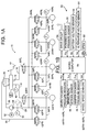
- the hydraulic circuit totally designated by 10 of a brake system of a vehicle (not shown) and having pairs of front and rear wheels (not shown) comprises wheel cylinders 20FR, 20FL, 20RR and 20RL for applying braking forces to front right, front left, rear tight and rear left ones of the wheels, respectively.
- the hydraulic circuit comprises a master cylinder 14 adapted to compress a brake fluid supplied from a reservoir 26 according to a depression of a brake pedal 12 by a driver, so as to deliver a pressurized brake fluid through passages 16 and 18 toward the wheel cylinders 20FL and 20FR, respectively.
- On-off valves 22FL and 22FR are provided in the passages 16 and 18, respectively, so as normally not to obstruct communication of the passages 16 and 18, while selectively interrupting the communication of the passages 16 and 18, respectively.
- the on-off valves 22FL and 22FR are solenoid actuated valves which are maintained in a through open condition such as shown in the figure when no electric current is supplied thereto, while they are changed over to a position interrupting the communication of the passages 16 and 18, respectively, when they are supplied with an electric current when an ignition switch (not shown) is turned on.
- the shown hydraulic circuit is ready for braking the pair of front wheels simply hydraulically according to a depression of the brake pedal 12 when the ignition switch is not turned on or the electric power source of the vehicle has failed for any reason, while when the ignition switch is turned on with a sound battery condition, the on-off valves 22FR and 22RL are changed over to theft closed position of interrupting the passages 16 and 18, so as to let the hydraulic circuit ready for operation with the brake fluid pressure source provided by a pump 34 under the control of electric control means described hereinbelow.
- the pump 34 is adapted to be selectively driven by an electric motor 32 powered by the above-mentioned battery via control means described in detail hereinbelow, so as to pump up the brake fluid supplied from the reservoir 26 through a suction passage 28 for providing a pressurized source of the brake fluid in an outlet passage 29 branching to passages 36FR, 36FL, 36RR and 36RL for supplying the pressurized brake fluid to the wheel cylinders 20FR, 20FL, 20RR and 20RL through on-off valves 40FR, 40FL, 40RR and 40RL, respectively.
- An accumulator 31 may be connected to the outlet passage 29.
- the on-off valves 40FR, 40FL, 40RR and 40RL are each of a normally closed type which maintains each of the supply passages 36FR, 36FL, 36RR and 36RL in an interrupted condition when no electric current is supplied thereto, and is selectively opened by a supply of an actuating electric current thereto.
- the wheel cylinders 20FR, 20FL, 20RR and 20RL are exhaustible through exhaust passages 38FR, 38FL, 38RR and 38RL including on-off valves 42FR, 42FL, 42RR and 42RL, respectively, toward an exhaust passage 30 leading to the reservoir 26.
- the on-off valves 42FR, 42FL, 42RR and 42RL are each also of a normally closed type which maintains each of the exhaust passages 38FR, 38FL, 38RR and 38RL in an interrupted condition when no electric current is supplied thereto, and is selectively opened by a supply of an actuating electric current.
- the pressures of the brake fluid in the wheel cylinders 20FR, 20FL, 20RR and 20RL are detected by pressure sensors 44FR, 44FL, 44RR and 44RL, respectively.
- the pressure of the brake fluid compressed by the master cylinder 14 is detected by a pressure sensor 48.
- the pressure of the brake fluid in the outlet passage 29 is detected by a pressure sensor 50.
- the changeover of each of the on-off valves 22FR and 22FL, the on-off valves 40FR-40RL and the on-off valves 42FR-42RL is controlled by electric control means 52 diagrammatically shown in Fig. 1B, or in more detail, by a microcomputer 54 thereof through a drive circuit 56.
- the microcomputer may be of a common type including a central processor unit (CPU), a read only memory (ROM), a random access memory (RAM), input and output port means and bi-lateral bus means interconnecting these elements, all not shown in detail in the figure.
- the checking of the battery may be executed according to a process such as described in the above-mentioned co-pending application No. (1231).
- a process such as described in the above-mentioned co-pending application No. (1231).
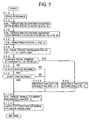
- Figs. 2-7 the device for controlling the brake system according to the present invention will be described in detail with respect to an embodiment thereof in the form of its operation of controlling the brake system shown in Figs. 1A and 1B.
- step 10 when the device is started for operation by a closure of the ignition switch (not shown), in step 10 signals such as shown in Fig. 1B are read in.
- a target value of the deceleration to be effected in the vehicle by a depression of the brake pedal by the driver is calculated in a manner described in U. S. Patent Application Serial No. 09/263,226 by two colleges of the present inventor.
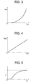
- step 20 by looking up a map such as shown in Fig. 3 stored in the ROM of the microcomputer 54, a target deceleration Gst is read out against a current value of the depression stroke Sp of the brake pedal by the driver.
- step 30 by looking up a map such as shown in Fig. 4 stored in the ROM, a target deceleration Gpt is read out against a current value of the master cylinder pressure Pm.
- the weighting of the parameters in the estimation of the deceleration of the vehicle to be targeted at is gradually shifted from a weighting on the brake pedal depression stroke to a weighting on the master cylinder pressure along with increase of the target deceleration, i.e. as a higher braking force is applied to the wheels.
- step 60 it is judged if the brake pedal is pumped by the driver when the vehicle is at a substantial standstill. This judgment is done according to such processes as shown by the flowchart of Fig. 6.
- step 61 it is judged if the vehicle speed V is substantially zero.
- the vehicle speed V will be available from the signals of the wheel speed sensors 60FR-60RL.
- step 62 the control proceeds to step 62, and count C of a counter (not shown) is reset to 0, and the control proceeds to step 70 of Fig. 2, while when the answer is yes, the control proceeds to step 63.
- step 63 it is judged if the stop lamp switch (STSW) 62 was changed over from OFF to ON.
- STSW stop lamp switch
- step 65 it is judged if the count C is larger than a predetermined threshold count value Co which may be 2 or 3.
- a predetermined threshold count value Co which may be 2 or 3.
- step 70 it is judged if the alternator (not shown) for charging the battery (not shown) of the vehicle is in its normal operating condition. This judgment will be available by checking the output voltage of the alternator relative to its rotation speed. When the answer is yes, the control proceeds to step 90, whereas when the answer is no, the control proceeds to step 100.
- step 90 it is judged if the battery of the vehicle is in its normal operating condition. As noted above, this judgment may be made as described in a co-pending application No. (1231). When the answer is yes, the control proceeds to step 110, whereas when the answer is no, the control proceeds to step 100.
- Fig. 7 shows an example of the relationship between Pwti and Gt, wherein a performance such as shown by a solid line A is followed with no restriction when the control has come to step 110 directly from step 90.
- step 110 the results of calculation of Pwti in step 110 are under the restriction imposed thereon in step 80 or 100.
- a restriction is imposed on the magnitude of Pwti such that none of Pwti higher than a pressure level Pwtb such as shown by a broken line B in Fig. 7 is available regardless of the results of calculation in step 50.
- step 80 a restriction is imposed on the magnitude of Pwti such that none of Pwti higher than a pressure level Pwtc such as shown by a dot-dash line C in Fig. 7 is available regardless of the results of calculation in step 50.
- the target values Pwti of the brake pressure to be attained in the wheel cylinders according to the depression of the brake pedal by the driver is temporarily suppressed not to be higher than the value C, so as to care the battery in a manner of saving a useless consumption of the battery.
- the target pressure Pwti of the brake pressure to be attained in the wheel cylinders according to the depression of the brake pedal by the driver is temporarily suppressed not to be higher than the value C in Fig. 7, so as to care the battery in a manner of reducing the load imposed thereon.
- step 120 the supply of the brake fluid pressures to the respective wheel cylinders is carried out according to the target wheel cylinder pressures Pwti calculated in the manner described above.
- Fig. 8 is a flowchart similar to that of Fig. 2, showing a modification of step 100 of Fig. 2.
- the steps corresponding to those shown in Fig. 2 are designated by the same step numbers as in Fig. 2.
- the effect of imposing the restriction of the pressure level B on the target wheel cylinder pressures Pwti as shown in Fig. 7 is provided by lowering the pressure level maintained in the accumulator 31 shown in Fig. 1.
- step 80 when the answer of step 80 is yes, the control proceeds to step 81, and a lower pressure limit Pal of the accumulator pressure at which the pump is automatically put on to replenish the accumulator and a higher pressure limit Pah of the accumulator pressure at which the replenishment driving of the pump is stopped are reset to their normal pressure values Palo and Paho, respectively.
- Palo ⁇ Paha Kaha
- step 83 the values of the lower and higher pressure limits Palo and Paho are temporarily lowered as much as ⁇ Pala and ⁇ Paha, respectively.
- Palo ⁇ Paha Kahb
- step 85 the values of the lower and higher pressure limits Palo and Paho are temporarily lowered as much as ⁇ Palb and ⁇ Pahb, respectively.
- step 86 it is judged if the brake fluid pressure Pp of the accumulator detected by the pressure sensor 50 is lower than the lower pressure limit Pal.
- the control proceeds to step 87, and the pump is driven by supplying an electric power to the motor 32 from the battery, and then the control proceeds to step 110.
- the control proceeds to step 86, and it is judged if the brake fluid pressure Pp is equal to or higher than the higher pressure limit Pah.
- the control proceeds to step 89, and the pump is stopped, whereas when the answer is no, the control proceeds to step 110.
- the brake fluid pressure of the accumulator 31 which substantially forms the pressurized brake fluid source of the brake system is normally maintained between Palo and Paho, whereas when it was detected that the alternator or battery is not normally operating, the accumulator pressure is lowered to be maintained between Palo- ⁇ Pala and Paho- ⁇ Paha, or Palo- ⁇ Palb and Paho- ⁇ pahb, respectivekly, wherein the magnitudes of ⁇ Pala and ⁇ Paha or ⁇ Palb and ⁇ Pahb are determined according to the degree of lowering of the output voltage of the alternator or the battery so that the battery is cared according to the degree of anticipation of the battery to fail due to an insufficient charging or the degree of the actual failing of the battery.
Abstract
Description
wherein the electric control means control the operation of the pump and the on-off valves such that the pressure of the brake fluid supplied to the wheel cylinders is restricted not to be higher than a first predetermined value lower than a standard output voltage of the battery when the battery detection means detect that the battery is not normally operating.
wherein Vao is a standard output voltage of the alternator at its normal standard operating condition, Va is the output voltage of the alternator at the normal standard operating condition, and Kala and Kaha are appropriate factors.
wherein Vbo is a standard output voltage of the battery at its normal standard operating condition, Vb is the output voltage of the battery at the normal standard operating condition, and Kalb and Kahb are appropriate factors.
Claims (8)
- A device for controlling an electro-hydraulic brake system of a vehicle having wheels, a battery, an alternator for charging the battery, and the electro-hydraulic brake system adapted to be energized by the battery and including wheel cylinders, a brake pedal, electric control means, a pump adapted to operate under a control of the electric control means for pressurizing a brake fluid, and on-off valves adapted to operate under a control of the electric control means for selectively supplying the brake fluid pressurized by the pump to each of the wheel cylinders, the device comprising:means for detecting if the battery is normally operating;
wherein the electric control means control the operation of the pump and the on-off valves such that the pressure of the brake fluid supplied to the wheel cylinders is restricted not to be higher than a first predetermined medium pressure value when the battery detection means detect that the battery is not normally operating. - A device according to claim 1, further comprising:means for detecting if the alternator is normally operating;
wherein the electric control means control the operation of the pump and the on-off valves such that the pressure of the brake fluid supplied to the wheel cylinders is restricted not to be higher than a second predetermined medium pressure value when the alternator detection means detect that the alternator is not normally operating. - A device according to claim 1, further comprising:means for detecting if the vehicle is substantially at a standstill; andmeans for detecting if the brake pedal is pumped by a driver;
wherein the electric control means control the operation of the pump and the on-off valves such that the pressure of the brake fluid supplied to the wheel cylinders is restricted not to be higher than a third predetermined medium pressure value when the brake pedal is pumped at a substantial standstill of the vehicle. - A device according to claim 2, further comprising:means for detecting if the vehicle is substantially at a standstill; andmeans for detecting if the brake pedal is pumped by a driver;
wherein the electric control means control the operation of the pump and the on-off valves such that the pressure of the brake fluid supplied to the wheel cylinders is restricted not to be higher than a third predetermined medium pressure value when the brake pedal is pumped at a substantial standstill of the vehicle. - A device according to claim 3, wherein the third predetermined medium pressure value is lower than the first predetermined medium pressure value.
- A device according to claim 4, wherein the third predetermined medium pressure value is lower than the first and second predetermined medium pressure values.
- A device according to claim 1, wherein the brake system further comprises an accumulator for the brake fluid pressurized by the pump, and the electric control means control the operation of the pump such that the pressure of the brake fluid supplied to the wheel cylinders is restricted not to be higher than the first predetermined medium pressure value by lowering the pressure of charging the accumulator when the battery detection means detect that the battery is not normally operating.
- A device according to claim 2, wherein the brake system further comprises an accumulator for the brake fluid pressurized by the pump, and the electric control means control the operation of the pump such that the pressure of the brake fluid supplied to the wheel cylinders is restricted not to be higher than the second predetermined medium pressure value by lowering the pressure of charging the accumulator when the alternator detection means detect that the alternator is not normally operating.
Applications Claiming Priority (2)
| Application Number | Priority Date | Filing Date | Title |
|---|---|---|---|
| JP36291198 | 1998-12-21 | ||
| JP36291198A JP3738584B2 (en) | 1998-12-21 | 1998-12-21 | Brake control device for vehicle |
Publications (3)
| Publication Number | Publication Date |
|---|---|
| EP1013529A2 true EP1013529A2 (en) | 2000-06-28 |
| EP1013529A3 EP1013529A3 (en) | 2002-09-18 |
| EP1013529B1 EP1013529B1 (en) | 2006-01-11 |
Family
ID=18478043
Family Applications (1)
| Application Number | Title | Priority Date | Filing Date |
|---|---|---|---|
| EP99122766A Expired - Lifetime EP1013529B1 (en) | 1998-12-21 | 1999-11-16 | Device for controlling brake system of vehicle with care for battery |
Country Status (5)
| Country | Link |
|---|---|
| US (1) | US6199957B1 (en) |
| EP (1) | EP1013529B1 (en) |
| JP (1) | JP3738584B2 (en) |
| DE (1) | DE69929390T2 (en) |
| ES (1) | ES2251814T3 (en) |
Cited By (4)
| Publication number | Priority date | Publication date | Assignee | Title |
|---|---|---|---|---|
| WO2002016181A1 (en) * | 2000-08-22 | 2002-02-28 | Continental Teves Ag & Co. Ohg | Method for operating a motor vehicle regulation system and device for carrying out said method |
| EP1693263A1 (en) * | 2005-02-17 | 2006-08-23 | Toyota Jidosha Kabushiki Kaisha | Electronically controlled hydraulic brake system |
| EP1795415A1 (en) * | 2005-12-08 | 2007-06-13 | Nissan Motor Company Limited | Vehicle braking apparatus |
| WO2011098877A1 (en) * | 2010-02-12 | 2011-08-18 | Toyota Jidosha Kabushiki Kaisha | Brake control system |
Families Citing this family (5)
| Publication number | Priority date | Publication date | Assignee | Title |
|---|---|---|---|---|
| JP4802706B2 (en) * | 2005-02-17 | 2011-10-26 | トヨタ自動車株式会社 | Electronically controlled hydraulic brake system |
| JP5011679B2 (en) * | 2005-08-26 | 2012-08-29 | トヨタ自動車株式会社 | Brake control device for vehicle |
| JP4569475B2 (en) | 2006-01-11 | 2010-10-27 | トヨタ自動車株式会社 | Brake control device |
| JP2010111230A (en) * | 2008-11-05 | 2010-05-20 | Toyota Motor Corp | Vehicle control device, brake electronic control device, and electric power steering device |
| JP5309984B2 (en) * | 2008-12-26 | 2013-10-09 | トヨタ自動車株式会社 | Brake control device |
Citations (1)
| Publication number | Priority date | Publication date | Assignee | Title |
|---|---|---|---|---|
| JPH0717375A (en) | 1993-07-06 | 1995-01-20 | Mazda Motor Corp | Automatic brake controller for vehicle and electricity feeding controller for automobile equipped with thereof |
Family Cites Families (9)
| Publication number | Priority date | Publication date | Assignee | Title |
|---|---|---|---|---|
| US4524311A (en) * | 1982-11-12 | 1985-06-18 | Mitsubishi Denki Kabushiki Kaisha | Control for pumping devices used in vehicles |
| JPS59213551A (en) * | 1983-05-17 | 1984-12-03 | Nissan Motor Co Ltd | Power source voltage monitoring circuit for anti-skid control system |
| JPS60128053A (en) * | 1983-12-13 | 1985-07-08 | Nissan Motor Co Ltd | Anti-skid control device |
| DE3435057C2 (en) * | 1984-09-25 | 1994-02-24 | Wabco Westinghouse Fahrzeug | Protection circuit against undervoltage in the electrical system of a motor vehicle |
| GB9315895D0 (en) * | 1993-07-31 | 1993-09-15 | Lucas Ind Plc | Anti-lock braking system |
| DE19603909B4 (en) * | 1996-02-03 | 2006-02-16 | Robert Bosch Gmbh | Method and device for checking the bleeding state of a hydraulic brake system of a vehicle |
| JPH10100884A (en) | 1996-09-27 | 1998-04-21 | Toyota Motor Corp | Brake fluid pressure control device |
| WO1999039954A1 (en) * | 1998-02-07 | 1999-08-12 | Continental Teves Ag & Co. Ohg | Electronically regulated brake actuation system for motor vehicles and method for controlling a brake actuation system of this type |
| DE19807369A1 (en) * | 1998-02-21 | 1999-08-26 | Bosch Gmbh Robert | Method and device for controlling a brake system |
-
1998
- 1998-12-21 JP JP36291198A patent/JP3738584B2/en not_active Expired - Lifetime
-
1999
- 1999-11-15 US US09/440,588 patent/US6199957B1/en not_active Expired - Lifetime
- 1999-11-16 ES ES99122766T patent/ES2251814T3/en not_active Expired - Lifetime
- 1999-11-16 EP EP99122766A patent/EP1013529B1/en not_active Expired - Lifetime
- 1999-11-16 DE DE69929390T patent/DE69929390T2/en not_active Expired - Lifetime
Patent Citations (1)
| Publication number | Priority date | Publication date | Assignee | Title |
|---|---|---|---|---|
| JPH0717375A (en) | 1993-07-06 | 1995-01-20 | Mazda Motor Corp | Automatic brake controller for vehicle and electricity feeding controller for automobile equipped with thereof |
Cited By (7)
| Publication number | Priority date | Publication date | Assignee | Title |
|---|---|---|---|---|
| WO2002016181A1 (en) * | 2000-08-22 | 2002-02-28 | Continental Teves Ag & Co. Ohg | Method for operating a motor vehicle regulation system and device for carrying out said method |
| EP1693263A1 (en) * | 2005-02-17 | 2006-08-23 | Toyota Jidosha Kabushiki Kaisha | Electronically controlled hydraulic brake system |
| EP1795415A1 (en) * | 2005-12-08 | 2007-06-13 | Nissan Motor Company Limited | Vehicle braking apparatus |
| US8210621B2 (en) | 2005-12-08 | 2012-07-03 | Nissan Motor Co., Ltd. | Vehicle brake device |
| WO2011098877A1 (en) * | 2010-02-12 | 2011-08-18 | Toyota Jidosha Kabushiki Kaisha | Brake control system |
| EP2650182A1 (en) * | 2010-02-12 | 2013-10-16 | Toyota Jidosha Kabushiki Kaisha | Brake control system |
| US9238454B2 (en) | 2010-02-12 | 2016-01-19 | Toyota Jidosha Kabushiki Kaisha | Brake control system |
Also Published As
| Publication number | Publication date |
|---|---|
| JP3738584B2 (en) | 2006-01-25 |
| JP2000177555A (en) | 2000-06-27 |
| DE69929390T2 (en) | 2006-08-31 |
| ES2251814T3 (en) | 2006-05-01 |
| US6199957B1 (en) | 2001-03-13 |
| DE69929390D1 (en) | 2006-04-06 |
| EP1013529A3 (en) | 2002-09-18 |
| EP1013529B1 (en) | 2006-01-11 |
Similar Documents
| Publication | Publication Date | Title |
|---|---|---|
| US6354672B1 (en) | Braking system wherein brake cylinder is communicated with pedal-operated pressure source upon failure of pump-operated pressure source | |
| JP3941388B2 (en) | Brake control device for vehicle | |
| US6244674B1 (en) | Brake control system for an electrically operated vehicle | |
| US9533663B2 (en) | Hydraulic brake system | |
| US6412882B1 (en) | Vehicle braking system having devices for controlling fluid flows between pressurizing and assisting chambers of master cylinder and pressure source and reservoir | |
| US8672419B2 (en) | Brake system | |
| US5558414A (en) | Vehicle braking system capable of controlling pump for optimum rate of change of brake cylinder pressure | |
| US20110266106A1 (en) | Brake control apparatus and brake control method | |
| US20120256477A1 (en) | Brake system | |
| US6238016B1 (en) | Device for controlling brake system of vehicle with checking of battery condition | |
| EP2176102B1 (en) | Brake control system and brake control method | |
| US6382737B1 (en) | Apparatus in braking system, for diagnosing pressurizing device based on fluid pressure detected during operation of the device prior to operation of the braking system | |
| US6216808B1 (en) | Brake control system for an electrically operated vehicle | |
| US6129425A (en) | Device for judging normal operation of brake system based upon correlation of pedal depression stroke and master cylinder pressure | |
| GB2336413A (en) | Vehicle brake control based upon pedal stoke and master cylinder pressure | |
| EP1013529B1 (en) | Device for controlling brake system of vehicle with care for battery | |
| EP0911235B1 (en) | Device for presuming accumulator pressure operative with pressure switches | |
| JP3680309B2 (en) | Brake control device for vehicle | |
| JP4089436B2 (en) | Brake control device for vehicle | |
| JP2004268868A (en) | Semibrake-by-wire type brake control device for vehicle | |
| JPH1198608A (en) | Apparatus and method for braking vehicle | |
| JP2811894B2 (en) | Hydraulic brake device | |
| JP4006791B2 (en) | Brake device for vehicle | |
| JP4677977B2 (en) | Brake device for a vehicle in which the distribution ratio between front and rear wheels is controlled according to the braking speed | |
| JPH079972A (en) | Slip controller for vehicle |
Legal Events
| Date | Code | Title | Description |
|---|---|---|---|
| PUAI | Public reference made under article 153(3) epc to a published international application that has entered the european phase |
Free format text: ORIGINAL CODE: 0009012 |
|
| AK | Designated contracting states |
Kind code of ref document: A2 Designated state(s): AT BE CH CY DE DK ES FI FR GB GR IE IT LI LU MC NL PT SE |
|
| AX | Request for extension of the european patent |
Free format text: AL;LT;LV;MK;RO;SI |
|
| PUAL | Search report despatched |
Free format text: ORIGINAL CODE: 0009013 |
|
| AK | Designated contracting states |
Kind code of ref document: A3 Designated state(s): AT BE CH CY DE DK ES FI FR GB GR IE IT LI LU MC NL PT SE |
|
| AX | Request for extension of the european patent |
Free format text: AL;LT;LV;MK;RO;SI |
|
| RIC1 | Information provided on ipc code assigned before grant |
Free format text: 7B 60T 8/88 A, 7B 60R 16/02 B, 7B 60T 17/18 B, 7B 60T 8/32 B, 7B 60T 7/04 B |
|
| 17P | Request for examination filed |
Effective date: 20021010 |
|
| AKX | Designation fees paid |
Designated state(s): DE ES FR IT |
|
| 17Q | First examination report despatched |
Effective date: 20030516 |
|
| GRAP | Despatch of communication of intention to grant a patent |
Free format text: ORIGINAL CODE: EPIDOSNIGR1 |
|
| GRAS | Grant fee paid |
Free format text: ORIGINAL CODE: EPIDOSNIGR3 |
|
| GRAA | (expected) grant |
Free format text: ORIGINAL CODE: 0009210 |
|
| AK | Designated contracting states |
Kind code of ref document: B1 Designated state(s): DE ES FR IT |
|
| PG25 | Lapsed in a contracting state [announced via postgrant information from national office to epo] |
Ref country code: IT Free format text: LAPSE BECAUSE OF FAILURE TO SUBMIT A TRANSLATION OF THE DESCRIPTION OR TO PAY THE FEE WITHIN THE PRESCRIBED TIME-LIMIT;WARNING: LAPSES OF ITALIAN PATENTS WITH EFFECTIVE DATE BEFORE 2007 MAY HAVE OCCURRED AT ANY TIME BEFORE 2007. THE CORRECT EFFECTIVE DATE MAY BE DIFFERENT FROM THE ONE RECORDED. Effective date: 20060111 |
|
| REF | Corresponds to: |
Ref document number: 69929390 Country of ref document: DE Date of ref document: 20060406 Kind code of ref document: P |
|
| REG | Reference to a national code |
Ref country code: ES Ref legal event code: FG2A Ref document number: 2251814 Country of ref document: ES Kind code of ref document: T3 |
|
| ET | Fr: translation filed | ||
| PLBE | No opposition filed within time limit |
Free format text: ORIGINAL CODE: 0009261 |
|
| STAA | Information on the status of an ep patent application or granted ep patent |
Free format text: STATUS: NO OPPOSITION FILED WITHIN TIME LIMIT |
|
| 26N | No opposition filed |
Effective date: 20061012 |
|
| PGFP | Annual fee paid to national office [announced via postgrant information from national office to epo] |
Ref country code: IT Payment date: 20101120 Year of fee payment: 12 |
|
| PG25 | Lapsed in a contracting state [announced via postgrant information from national office to epo] |
Ref country code: IT Free format text: LAPSE BECAUSE OF NON-PAYMENT OF DUE FEES Effective date: 20121116 |
|
| REG | Reference to a national code |
Ref country code: DE Ref legal event code: R084 Ref document number: 69929390 Country of ref document: DE Effective date: 20130829 |
|
| REG | Reference to a national code |
Ref country code: FR Ref legal event code: PLFP Year of fee payment: 17 |
|
| REG | Reference to a national code |
Ref country code: FR Ref legal event code: PLFP Year of fee payment: 18 |
|
| REG | Reference to a national code |
Ref country code: FR Ref legal event code: PLFP Year of fee payment: 19 |
|
| REG | Reference to a national code |
Ref country code: FR Ref legal event code: PLFP Year of fee payment: 20 |
|
| PGFP | Annual fee paid to national office [announced via postgrant information from national office to epo] |
Ref country code: DE Payment date: 20181106 Year of fee payment: 20 |
|
| PGFP | Annual fee paid to national office [announced via postgrant information from national office to epo] |
Ref country code: ES Payment date: 20181204 Year of fee payment: 20 Ref country code: FR Payment date: 20181011 Year of fee payment: 20 |
|
| REG | Reference to a national code |
Ref country code: DE Ref legal event code: R071 Ref document number: 69929390 Country of ref document: DE |
|
| REG | Reference to a national code |
Ref country code: ES Ref legal event code: FD2A Effective date: 20220128 |
|
| PG25 | Lapsed in a contracting state [announced via postgrant information from national office to epo] |
Ref country code: ES Free format text: LAPSE BECAUSE OF EXPIRATION OF PROTECTION Effective date: 20191117 |