EP2649498B1 - Power and data connector - Google Patents
Power and data connector Download PDFInfo
- Publication number
- EP2649498B1 EP2649498B1 EP11846102.9A EP11846102A EP2649498B1 EP 2649498 B1 EP2649498 B1 EP 2649498B1 EP 11846102 A EP11846102 A EP 11846102A EP 2649498 B1 EP2649498 B1 EP 2649498B1
- Authority
- EP
- European Patent Office
- Prior art keywords
- power
- interface
- axis
- data connector
- optical
- Prior art date
- Legal status (The legal status is an assumption and is not a legal conclusion. Google has not performed a legal analysis and makes no representation as to the accuracy of the status listed.)
- Active
Links
Images

Classifications
-
- G—PHYSICS
- G02—OPTICS
- G02B—OPTICAL ELEMENTS, SYSTEMS OR APPARATUS
- G02B6/00—Light guides; Structural details of arrangements comprising light guides and other optical elements, e.g. couplings
- G02B6/24—Coupling light guides
- G02B6/36—Mechanical coupling means
- G02B6/38—Mechanical coupling means having fibre to fibre mating means
- G02B6/3807—Dismountable connectors, i.e. comprising plugs
- G02B6/381—Dismountable connectors, i.e. comprising plugs of the ferrule type, e.g. fibre ends embedded in ferrules, connecting a pair of fibres
- G02B6/3817—Dismountable connectors, i.e. comprising plugs of the ferrule type, e.g. fibre ends embedded in ferrules, connecting a pair of fibres containing optical and electrical conductors
-
- G—PHYSICS
- G02—OPTICS
- G02B—OPTICAL ELEMENTS, SYSTEMS OR APPARATUS
- G02B6/00—Light guides; Structural details of arrangements comprising light guides and other optical elements, e.g. couplings
- G02B6/24—Coupling light guides
- G02B6/36—Mechanical coupling means
- G02B6/38—Mechanical coupling means having fibre to fibre mating means
- G02B6/3807—Dismountable connectors, i.e. comprising plugs
- G02B6/3897—Connectors fixed to housings, casing, frames or circuit boards
-
- H—ELECTRICITY
- H01—ELECTRIC ELEMENTS
- H01B—CABLES; CONDUCTORS; INSULATORS; SELECTION OF MATERIALS FOR THEIR CONDUCTIVE, INSULATING OR DIELECTRIC PROPERTIES
- H01B11/00—Communication cables or conductors
- H01B11/22—Cables including at least one electrical conductor together with optical fibres
-
- H—ELECTRICITY
- H01—ELECTRIC ELEMENTS
- H01R—ELECTRICALLY-CONDUCTIVE CONNECTIONS; STRUCTURAL ASSOCIATIONS OF A PLURALITY OF MUTUALLY-INSULATED ELECTRICAL CONNECTING ELEMENTS; COUPLING DEVICES; CURRENT COLLECTORS
- H01R11/00—Individual connecting elements providing two or more spaced connecting locations for conductive members which are, or may be, thereby interconnected, e.g. end pieces for wires or cables supported by the wire or cable and having means for facilitating electrical connection to some other wire, terminal, or conductive member, blocks of binding posts
- H01R11/11—End pieces or tapping pieces for wires, supported by the wire and for facilitating electrical connection to some other wire, terminal or conductive member
- H01R11/30—End pieces held in contact by a magnet
-
- H—ELECTRICITY
- H01—ELECTRIC ELEMENTS
- H01R—ELECTRICALLY-CONDUCTIVE CONNECTIONS; STRUCTURAL ASSOCIATIONS OF A PLURALITY OF MUTUALLY-INSULATED ELECTRICAL CONNECTING ELEMENTS; COUPLING DEVICES; CURRENT COLLECTORS
- H01R13/00—Details of coupling devices of the kinds covered by groups H01R12/70 or H01R24/00 - H01R33/00
- H01R13/02—Contact members
- H01R13/22—Contacts for co-operating by abutting
- H01R13/24—Contacts for co-operating by abutting resilient; resiliently-mounted
-
- H—ELECTRICITY
- H01—ELECTRIC ELEMENTS
- H01R—ELECTRICALLY-CONDUCTIVE CONNECTIONS; STRUCTURAL ASSOCIATIONS OF A PLURALITY OF MUTUALLY-INSULATED ELECTRICAL CONNECTING ELEMENTS; COUPLING DEVICES; CURRENT COLLECTORS
- H01R13/00—Details of coupling devices of the kinds covered by groups H01R12/70 or H01R24/00 - H01R33/00
- H01R13/62—Means for facilitating engagement or disengagement of coupling parts or for holding them in engagement
- H01R13/6205—Two-part coupling devices held in engagement by a magnet
-
- H—ELECTRICITY
- H01—ELECTRIC ELEMENTS
- H01R—ELECTRICALLY-CONDUCTIVE CONNECTIONS; STRUCTURAL ASSOCIATIONS OF A PLURALITY OF MUTUALLY-INSULATED ELECTRICAL CONNECTING ELEMENTS; COUPLING DEVICES; CURRENT COLLECTORS
- H01R13/00—Details of coupling devices of the kinds covered by groups H01R12/70 or H01R24/00 - H01R33/00
- H01R13/62—Means for facilitating engagement or disengagement of coupling parts or for holding them in engagement
- H01R13/629—Additional means for facilitating engagement or disengagement of coupling parts, e.g. aligning or guiding means, levers, gas pressure electrical locking indicators, manufacturing tolerances
-
- H—ELECTRICITY
- H01—ELECTRIC ELEMENTS
- H01R—ELECTRICALLY-CONDUCTIVE CONNECTIONS; STRUCTURAL ASSOCIATIONS OF A PLURALITY OF MUTUALLY-INSULATED ELECTRICAL CONNECTING ELEMENTS; COUPLING DEVICES; CURRENT COLLECTORS
- H01R24/00—Two-part coupling devices, or either of their cooperating parts, characterised by their overall structure
- H01R24/60—Contacts spaced along planar side wall transverse to longitudinal axis of engagement
Definitions
- US 2010/080563 A1 discloses a connector system having a connector insert and a connector receptacle for mating with the connector insert.
- the connector insert includes a raised guide protruding from the surface of an insert housing and a recess, in which pins and a fiber-optic line are located.
- the raised guide of the connector insert fits into a recess of the connector receptacle.
- a raised guide of the connector receptacle fits into the recess of the connector insert.
- US 2004/209489 A1 discloses an automatic docking system utilizing magnetic attraction to align and dock a mobile device with a base device.
- a device connection interface coupled with the mobile device includes a plurality of connectors and attractive material array.
- EP 0289208 discloses a data connector according to the preamble of independent claim 1.
- the present invention relates to a power and data connector.
- Advantageous embodiments are defined in dependent claims 2 to 9.
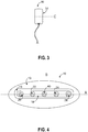
- FIG. 1 shows a nonlimiting example of a power and data connector 10.
- Power and data connectors in accordance with the present disclosure such as power and data connector 10, provide a mechanically simple and aesthetically pleasing mechanism for delivering power and/or data to and/or from an electronic device, such as electronic device 12 of FIG. 2 .
- power and data connectors in accordance with the present disclosure include a planar connection surface that is substantially flat and protrudes in front of the rest of the power and data connector.
- FIG. 1 shows an example planar connection surface 14 of power and data connector 10.
- the planar connection surface is designed to mate with a planar receptor surface of the electronic device.
- FIG. 2 shows an example planar receptor surface 16 of electronic device 12.
- FIG. 1 also shows a lip surface 13 and a tapered extension 15.
- the tapered extension 15 protrudes from the lip surface 13, and the planar connection surface 14 is located at a terminal end of the tapered extension.
- FIG. 2 shows power and data connector 10 magnetically held in place relative to a planar receptor surface (hidden by power and data connector 10).
- various power interfaces and/or optical or electrical data interfaces of the power and data connector are operatively coupled to complementary power interfaces and optical data interfaces of the electronic device.
- power and/or data may be transferred to and/or from the electronic device via the power and data connector.
- the electronic device can be designed with a substantially smooth surface. It is believed that the substantially smooth surface allowed by the herein disclosed power and data connector is aesthetically pleasing, is resistant to mechanical failures associated with mechanically complicated designs, is easy to keep clean, and provides countless other benefits.
- Planar connection surface 14 is symmetrical about a first axis A and symmetrical about a second axis B that is perpendicular to axis A.
- Axis A and axis B are perpendicular to a connection axis C (shown in FIG. 3 ) of the planar connection surface.
- the symmetrical shape of the planar connection surface allows the power and data connector to be connected to an electronic device in either of at least two different orientations. In other words, the power and data connector may be connected with a first orientation or a second orientation that is rotated one hundred eighty degrees relative to the first orientation.
- Power and data connectors in accordance with the present disclosure include one or more pairs of power interfaces. Such power interfaces may be electrical conductors, for example.
- power and data connector 10 includes a first power interface 22 and a second power interface 24 on planar connection surface 14. As shown in FIGS. 1 and 4 , first power interface 22 and second power interface 24 are aligned with axis A. Furthermore, first power interface 22 and second power interface 24 are each spaced the same distance away from axis B so that the first power interface and the second power interface are symmetrical about axis B.
- Each power interface is configured to operatively couple with a complementary power interface of a power and data connector receptor such that electrical power is transferred between the first power interface and the complementary power interface.
- one power interface may be held at a first voltage and the other power interface may be held at a different voltage such that a voltage differential is established for providing a direct current for powering an electronic device.
- the symmetrical arrangement of the power interfaces allows the power and data connector to be orientation agnostic.
- Power and data connectors in accordance with the present disclosure may include one or more power interfaces configured to ground the power and data connector.
- power and data connector 10 includes a ground power interface 26 and a ground power interface 28.
- the planar connection surface or another aspect of the power and data connector may be used to ground the power and data connector.
- power and data connector 10 includes two working power interfaces for establishing a DC voltage and two ground power interfaces for grounding the power and data connector.
- power and data connectors may include virtually any number of working and/or grounding power interfaces without departing from the scope of this disclosure.
- the power interfaces may extend parallel to connection axis C past the planar connection surface 14 and all other portions of the power and data connector.
- the power interfaces may be the forward most aspect of the power and data connector.
- the power interfaces are recessed into the planar connection surface parallel to the connection axis C.
- optical interface(s) may extend or recede similar to the power interfaces.
- the amount of extension and/or recession will be relatively minor - e.g., less than two millimeters.
- any extension and/or recession may be accommodated by complementary recession and/or extension of the power and data connector receptor, such that reliable connections can be established between the power and data connector and the electronic device.
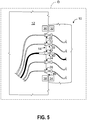
- FIG. 5 shows a cross-sectional view of a plane D, which is illustrated in FIG. 2 .
- a power interface such as power interface 22
- a connection assistant 30 may be operatively connected to a connection assistant 30.
- Connection assistant resiliently biases the power interface past the planar connection surface 14 parallel to connection axis C.
- the connection assistant provides the power interface with a variable amount of extension so that a solid contact may be made with a complementary power interface of the electronic device.
- the electronic device may alternatively or additionally include a connection assistant to resiliently bias the power interfaces of the electronic device.
- the connection assistant may include a spring in some embodiments.
- power and data connector 10 includes a first magnetic attractor 32 and a second magnetic attractor 34 that are configured to cooperate with magnetic attractor 36 and magnetic attractor 38 of electronic device 12 to magnetically hold the power and data connector 10 in place relative to the electronic device.
- the magnetic attractors are flush with or recessed behind the planar connection surface 14, as shown in FIG. 5 .
- one or more magnetic attractors may alternatively or additionally be flush with or recessed behind the lip surface and/or the tapered extension.
- the magnetic attractors may include a permanent magnet and/or an electromagnet. While the illustrated embodiment shows a power and data connector that includes two magnetic attractors, it is to be understood that virtually any number of magnetic attractors may be used.
- Power and data connectors in accordance with the present disclosure may include one or more electrical or optical interfaces configured to transmit data signals.
- power and data connector 10 includes optical interface 40 in the form of an optical fiber connector that terminates a fiber optic cable capable of transmitting data signals in the form of light.
- optical interface 40 is aligned with axis A and axis B at a center of planar connection surface 14.
- a pair of optical interfaces may be aligned with axis A and spaced the same distance away from axis B so that the pair of optical interfaces are symmetrical about axis B.
- the optical interface is configured to operatively couple with a complementary optical interface of a power and data connector receptor. In this way, optical signals may be transferred between the optical interface of the power and data connector and the complementary optical interface of the electronic device.
- optical interface 40 may be operatively connected to a connection assistant 42 resiliently biasing that optical interface past planar connection surface 14.
- electronic device 12 includes a housing 44 and a plurality of power and data connector receptors to selectively couple with power and data connectors.
- electronic device includes an empty power and data connector receptor 17 and a power and data connector receptor 18 that is occupied by power and data connector 10.
- a device may include virtually any number of power and data connector receptors without departing from the scope of this disclosure.
- the power and data connector receptors may be formed as an integral part of the device chassis or housing so that there is not a separate user-visible connector housing.
- the power and data connector may include a tapered opening that recedes to the planar receptor surface at its terminal end.
- the tapered opening may be sized and shaped to mate with the tapered extension of the power and data connector.
- the tapered arrangement helps guide the power and data connector into a mated arrangement with the power and data connector receptor in either of two orientations (i.e., 180 degree rotation). In the mated arrangement, the magnetic attractors can hold the power and data connector in place.
- the power and data connector receptors may be located at different sites around housing 44.
- An auxiliary device or power source may be connected to any of the different connector receptors via a power and data connector, thus providing connection flexibility that may facilitate using the electronic device in a desired orientation, with a desired case or covering, and/or with a desired grip.
- two or more auxiliary devices may be simultaneously connected to the electronic device via different power and data connectors.
- the plurality of connector receptors may be operatively connected to one another such that power received via one connector receptor may be output via another connector receptor; and data received via an optical interface of one connector receptor may be output via an optical interface of another connector receptor.
- power and/or data may not only be delivered to the electronic device, but also through the electronic device to another auxiliary device.
- each power and data connector receptor may be configured to complement the power and data connector.
- each of the plurality of power and data connector receptors may include a receptor surface 16.
- the receptor surface may be planar.
- the receptor surface may be recessed less than six millimeters from the housing so as to provide a substantially continuous and uninterrupted surface from the housing and across the connector receptor.
- the overall smoothness of the connector receptor in relation to the housing provides a clean appearance that does not include any protrusions that can be easily broken or large gaps into which debris and other contaminants may collect. The overall smoothness is also thought to produce an aesthetically pleasing appearance.
- the connector receptor may be substantially symmetrical. Furthermore, the connector receptor may include power interfaces and/or optical interfaces positioned to align with the corresponding power interfaces and optical interfaces of the power and data connector when the power and data connector is magnetically held to the electronic device. To facilitate such magnetic holding, the connector receptor may include one or more magnetic attractors flush with or recessed behind the receptor surface.
Landscapes
- Physics & Mathematics (AREA)
- General Physics & Mathematics (AREA)
- Optics & Photonics (AREA)
- Details Of Connecting Devices For Male And Female Coupling (AREA)
- Connector Housings Or Holding Contact Members (AREA)
- Mechanical Coupling Of Light Guides (AREA)
- Coupling Device And Connection With Printed Circuit (AREA)
- Magnetic Heads (AREA)
Applications Claiming Priority (3)
| Application Number | Priority Date | Filing Date | Title |
|---|---|---|---|
| US42158710P | 2010-12-09 | 2010-12-09 | |
| US13/070,331 US8596881B2 (en) | 2010-12-09 | 2011-03-23 | Power and data connector |
| PCT/US2011/063339 WO2012078526A2 (en) | 2010-12-09 | 2011-12-05 | Power and data connector |
Publications (3)
| Publication Number | Publication Date |
|---|---|
| EP2649498A2 EP2649498A2 (en) | 2013-10-16 |
| EP2649498A4 EP2649498A4 (en) | 2014-06-11 |
| EP2649498B1 true EP2649498B1 (en) | 2021-04-14 |
Family
ID=46199467
Family Applications (1)
| Application Number | Title | Priority Date | Filing Date |
|---|---|---|---|
| EP11846102.9A Active EP2649498B1 (en) | 2010-12-09 | 2011-12-05 | Power and data connector |
Country Status (6)
| Country | Link |
|---|---|
| US (3) | US8596881B2 (enExample) |
| EP (1) | EP2649498B1 (enExample) |
| JP (2) | JP2013545256A (enExample) |
| CN (1) | CN102570166A (enExample) |
| AU (1) | AU2011338672B2 (enExample) |
| WO (1) | WO2012078526A2 (enExample) |
Families Citing this family (80)
| Publication number | Priority date | Publication date | Assignee | Title |
|---|---|---|---|---|
| AU2015264922A1 (en) * | 2008-09-30 | 2015-12-24 | Apple Inc. | Magnetic connector with optical signal path |
| US9300081B2 (en) | 2010-02-02 | 2016-03-29 | Charles Albert Rudisill | Interposer connectors with magnetic components |
| DE202010017352U1 (de) * | 2010-05-10 | 2011-10-27 | Rosenberger Hochfrequenztechnik Gmbh & Co. Kg | Elektrisches Verbindungssystem |
| US9142926B2 (en) * | 2010-07-19 | 2015-09-22 | Chou Hsien Tsai | Electrical connector for bidirectional plug insertion |
| US8596881B2 (en) * | 2010-12-09 | 2013-12-03 | Microsoft Corporation | Power and data connector |
| CN102709723B (zh) * | 2011-03-28 | 2015-05-13 | 泰科电子(上海)有限公司 | Usb连接器 |
| US8460008B1 (en) * | 2012-02-21 | 2013-06-11 | Cheng Uei Precision Industry Co., Ltd. | Electrical connector |
| US8465296B1 (en) * | 2012-02-21 | 2013-06-18 | Cheng Uei Precision Industry Co., Ltd. | Electrical connector |
| US9158383B2 (en) | 2012-03-02 | 2015-10-13 | Microsoft Technology Licensing, Llc | Force concentrator |
| US9426905B2 (en) * | 2012-03-02 | 2016-08-23 | Microsoft Technology Licensing, Llc | Connection device for computing devices |
| US9075566B2 (en) | 2012-03-02 | 2015-07-07 | Microsoft Technoogy Licensing, LLC | Flexible hinge spine |
| US9225126B2 (en) * | 2013-04-09 | 2015-12-29 | Magno Plug Products Inc. | Magnetically actuated AC power connector |
| US20130300590A1 (en) | 2012-05-14 | 2013-11-14 | Paul Henry Dietz | Audio Feedback |
| CA2873866A1 (en) | 2012-05-18 | 2013-11-21 | Adc Telecommunications, Inc. | Connectors and adapters with auto-latching features |
| USD684538S1 (en) | 2012-06-08 | 2013-06-18 | Apple Inc. | Adapter |
| USD721331S1 (en) | 2012-06-10 | 2015-01-20 | Apple Inc. | Electronic device |
| US9075205B2 (en) | 2012-07-11 | 2015-07-07 | Tyco Electronics Corporation | Connectors and adapters with auto-latching features |
| US9306322B2 (en) | 2012-08-23 | 2016-04-05 | Stryker Corporation | Patient support apparatus connectors |
| US9645336B2 (en) * | 2012-09-10 | 2017-05-09 | Corning Optical Communications LLC | Optical connections having magnetic coupling |
| WO2014062181A1 (en) | 2012-10-18 | 2014-04-24 | Hewlett-Packard Development Company, L.P. | Polarity control for a flat connector |
| US20140120746A1 (en) * | 2012-10-24 | 2014-05-01 | Rostislav Persion | Electrical and fiber optic connector with magnetic electrical contacts |
| US8790120B2 (en) * | 2012-10-30 | 2014-07-29 | Htc Corporation | Electric connector, bracket and electric connector assembly |
| KR20140060770A (ko) * | 2012-11-12 | 2014-05-21 | 삼성전자주식회사 | 케이블 컨넥터 장치 |
| US9389369B2 (en) | 2012-12-13 | 2016-07-12 | Corning Cable Systems Llc | Optical port having minimalist footprint |
| US9395497B2 (en) * | 2012-12-13 | 2016-07-19 | Corning Optical Communications LLC | Optical port having one or more alignment features |
| KR101945250B1 (ko) * | 2012-12-14 | 2019-02-07 | 삼성전자 주식회사 | 단말기의 커넥팅 시스템 및 이에 포함되는 단말기 접속 인터페이스와 커넥터, 이를 지원하는 단말기 운용 방법 |
| US9468498B2 (en) * | 2012-12-20 | 2016-10-18 | Cook Medical Technologies Llc | Magnetic activation of monopolar and bipolar devices |
| US10680383B2 (en) | 2013-03-14 | 2020-06-09 | Apex Technologies, Inc. | Linear electrode systems for module attachment with non-uniform axial spacing |
| AU2014234239B2 (en) * | 2013-03-21 | 2019-02-14 | Vorwerk & Co. Interholding Gmbh | Kitchen appliance operable by electric motor, data memory element, and combination of a kitchen appliance operable by electric motor and a data memory element |
| CN105408793B (zh) * | 2013-04-12 | 2018-09-14 | 康宁光电通信有限责任公司 | 具有整体对准结构的光学连接 |
| CN203445280U (zh) * | 2013-07-26 | 2014-02-19 | 富士康(昆山)电脑接插件有限公司 | 电连接器 |
| US9300083B2 (en) * | 2013-09-30 | 2016-03-29 | Apple Inc. | Stackable magnetically-retained connector interface |
| AU2015206269A1 (en) * | 2014-01-17 | 2016-07-07 | Gojo Industries, Inc. | Powered communication connection |
| CN203800333U (zh) * | 2014-01-20 | 2014-08-27 | 富士康(昆山)电脑接插件有限公司 | 电连接器组件 |
| JP2015185214A (ja) * | 2014-03-20 | 2015-10-22 | セイコーエプソン株式会社 | コネクター、無線通信モジュール、無線通信装置、及び、電子機器 |
| US9017092B1 (en) | 2014-05-07 | 2015-04-28 | Microsoft Technology Licensing, Llc | Electronic connector |
| US9413087B2 (en) * | 2014-05-30 | 2016-08-09 | Microsoft Technology Licensing, Llc | Data and power connector |
| US9531118B2 (en) | 2014-07-10 | 2016-12-27 | Norman R. Byrne | Electrical power coupling with magnetic connections |
| US9141086B1 (en) * | 2014-08-11 | 2015-09-22 | Apple Inc. | Magnetic actuated attachment mechanisms for wearable devices |
| DE102014113024A1 (de) * | 2014-09-10 | 2016-03-10 | Dr. Ing. H.C. F. Porsche Aktiengesellschaft | Elektrisches Anschlussmodul für ein Kraftfahrzeug |
| KR20160059270A (ko) * | 2014-11-18 | 2016-05-26 | 삼성전자주식회사 | 전기 커넥터 장치 |
| US10374353B2 (en) * | 2015-04-29 | 2019-08-06 | Michael Archuleta | Magnetic coupling for bulbs and sockets |
| US9728915B2 (en) | 2015-05-19 | 2017-08-08 | Microsoft Technology Licensing, Llc | Tapered-fang electronic connector |
| US9941627B2 (en) | 2015-09-30 | 2018-04-10 | Apple Inc. | Magnetic surface contacts |
| EP3159978B1 (en) * | 2015-10-20 | 2020-11-25 | ITT Manufacturing Enterprises LLC | Receptacle, connector and connection interfaces with coupling mechanisms |
| KR102063936B1 (ko) * | 2015-10-20 | 2020-01-08 | 주식회사 엘지화학 | 마그네틱 연결 구조를 이용하여 연결된 복수의 전지 모듈을 포함하는 전력 저장 시스템 |
| EP3677226B1 (en) | 2015-11-20 | 2021-12-22 | Tc1 Llc | Improved connectors and cables for use with ventricle assist systems |
| US9660380B1 (en) | 2016-01-22 | 2017-05-23 | Microsoft Technology Licensing, Llc | Alignment tolerant electronic connector |
| US10177507B2 (en) | 2016-02-12 | 2019-01-08 | Norman R. Byrne | Electrical power load switch with connection sensor |
| US9705243B1 (en) | 2016-02-12 | 2017-07-11 | Microsoft Technology Licensing, Llc | Electronic connector with C-shaped tapered extension |
| JP3204474U (ja) * | 2016-03-16 | 2016-06-02 | 裕雄 范 | 充電ジョイント |
| US10469175B2 (en) | 2016-04-15 | 2019-11-05 | Multidyne Electronics, Inc. | Stackable fiber optic transmitter/receiver modules |
| US9991962B2 (en) | 2016-04-15 | 2018-06-05 | Multidyne Electronics, Inc. | Stackable fiber optic transmitter/receiver modules |
| US10658793B2 (en) | 2016-07-21 | 2020-05-19 | Canary Connect, Inc. | Reversible power and data connector assembly |
| US10541557B2 (en) | 2016-10-07 | 2020-01-21 | Norman R. Byrne | Electrical power cord with intelligent switching |
| GB2555493A (en) * | 2016-11-01 | 2018-05-02 | Roli Ltd | Electrical connector |
| US11491884B2 (en) | 2017-01-19 | 2022-11-08 | Curtis Instruments Inc. | Magnetic charger connector for wheelchair |
| JP2021507475A (ja) * | 2017-12-21 | 2021-02-22 | アイディール インダストリーズ,インク. | 転換力ラッチングシステム |
| KR102420986B1 (ko) * | 2018-01-15 | 2022-07-14 | 삼성전자주식회사 | 컨택 구조 및 이를 포함하는 전자 장치 |
| US10511127B2 (en) | 2018-03-20 | 2019-12-17 | Microsoft Technology Licensing, Llc | High-speed electronic connector |
| US11527909B2 (en) | 2018-05-11 | 2022-12-13 | Assembled Products Corporation | Magnetic charging device |
| US11360309B2 (en) | 2018-06-14 | 2022-06-14 | Wilcox Industries Corp. | High speed hot shoe |
| US10886646B2 (en) | 2018-06-14 | 2021-01-05 | Wilcox Industries Corp. | High speed hot shoe |
| GB2574839A (en) * | 2018-06-19 | 2019-12-25 | Ultra Electronics Ltd | Apparel fastener |
| US10522943B1 (en) * | 2018-09-21 | 2019-12-31 | Calista A. Termini | Magnetically securing detachable electronic cable assembly and method |
| CN109304043B (zh) * | 2018-11-20 | 2020-12-15 | 深圳市优必选科技有限公司 | 电子积木模块及电子积木套件 |
| US10718996B2 (en) | 2018-12-19 | 2020-07-21 | Arlo Technologies, Inc. | Modular camera system |
| JP7077984B2 (ja) * | 2019-02-13 | 2022-05-31 | 株式会社オートネットワーク技術研究所 | コネクタ装置 |
| US11367978B2 (en) | 2019-03-29 | 2022-06-21 | Canon U.S.A., Inc. | Self-aligning and self-assembling connectors |
| US11424561B2 (en) | 2019-07-03 | 2022-08-23 | Norman R. Byrne | Outlet-level electrical energy management system |
| US11283215B2 (en) * | 2020-07-13 | 2022-03-22 | Xerox Corporation | Magnetic connector system and method of using |
| GB2597969B (en) * | 2020-08-12 | 2023-06-14 | Draeger Safety Uk Ltd | Connector systems for breathing apparatus |
| GB2615679B (en) * | 2020-08-12 | 2024-10-16 | Draeger Safety Uk Ltd | Connector systems for breathing apparatus |
| WO2022056380A1 (en) | 2020-09-14 | 2022-03-17 | Daedalus Labs Llc | Systems with wireless interface for removable support accessories |
| TWI773460B (zh) * | 2021-07-26 | 2022-08-01 | 和碩聯合科技股份有限公司 | 彈簧連接器 |
| US20230139373A1 (en) * | 2021-11-04 | 2023-05-04 | Hubbell Incorporated | Breakaway electrical connector |
| US11757229B2 (en) * | 2021-11-11 | 2023-09-12 | Onanon, Inc. | Electromagnetic Electrical Connector System |
| JP2023141150A (ja) * | 2022-03-23 | 2023-10-05 | 株式会社トプコン | 眼科装置 |
| US12470016B2 (en) * | 2022-06-24 | 2025-11-11 | Thales Avionics, Inc. | Floating pogo connectors for tablet computers of aircraft inflight entertainment systems and crew terminals |
| EP4454696B1 (de) * | 2023-04-26 | 2025-12-10 | Berlin Heart GmbH | Steuereinrichtung für eine blutpumpe |
Citations (3)
| Publication number | Priority date | Publication date | Assignee | Title |
|---|---|---|---|---|
| EP0289208A2 (en) * | 1987-04-30 | 1988-11-02 | Sony Corporation | Electrical connector |
| US20050255719A1 (en) * | 2002-09-13 | 2005-11-17 | Hermann Heidlein | Electric connecting device |
| US20060145663A1 (en) * | 2005-01-05 | 2006-07-06 | Microsoft Corporation | Device interfaces with non-mechanical securement mechanisms |
Family Cites Families (45)
| Publication number | Priority date | Publication date | Assignee | Title |
|---|---|---|---|---|
| JPS4817598Y1 (enExample) * | 1968-04-18 | 1973-05-19 | ||
| JPS509990B1 (enExample) * | 1970-06-01 | 1975-04-17 | ||
| US4193657A (en) * | 1978-07-28 | 1980-03-18 | Slone Ralph W | Electrical cable termination |
| JPS5841985U (ja) * | 1981-09-14 | 1983-03-19 | 石崎 勝也 | プラグ |
| JPS59103478A (ja) | 1982-12-03 | 1984-06-14 | Sony Corp | 磁気テープ記録再生装置 |
| US5192229A (en) * | 1992-05-29 | 1993-03-09 | Sonic Electric, Inc. | Electrical cable termination |
| JPH076817A (ja) | 1993-06-15 | 1995-01-10 | Hitachi Ltd | コネクト装置 |
| US5700161A (en) * | 1995-10-13 | 1997-12-23 | Baker Hughes Incorporated | Two-piece lead seal pothead connector |
| JPH09258072A (ja) | 1996-01-19 | 1997-10-03 | Sony Corp | 光学データ伝送用接続装置 |
| US6305992B1 (en) | 1996-10-17 | 2001-10-23 | The Whitaker Corporation | Electrical connector having a housing and an electrical contact and electrical contact |
| US5867621A (en) * | 1997-04-23 | 1999-02-02 | Siecor Corporation | Adapter and guide pin assembly for coupling of fiber optic connectors |
| JP2000021474A (ja) * | 1998-06-30 | 2000-01-21 | Matsushita Electric Works Ltd | コネクタ |
| US6361342B1 (en) * | 2000-09-11 | 2002-03-26 | Baker Hughes Incorporated | Pothead with pressure energized lip seals |
| US6558167B2 (en) * | 2001-01-22 | 2003-05-06 | Grote Industries, Inc. | Nosebox with interchangeable connector assemblies for tractors and trailers |
| US6705880B2 (en) * | 2001-03-30 | 2004-03-16 | Douglas R. Rhude | Male plug protector for trailer wiring harness |
| JP4197588B2 (ja) * | 2001-09-21 | 2008-12-17 | 旭硝子株式会社 | プラスチック光ファイバ用コンセントおよびプラグを含む組立体 |
| AU2003901297A0 (en) * | 2003-03-20 | 2003-04-03 | Silverbrook Research Pty Ltd | Systems and apparatus (fpd001) |
| US20040209489A1 (en) | 2003-04-21 | 2004-10-21 | Clapper Edward O. | Apparatus for automatic docking |
| DE10332325A1 (de) | 2003-07-16 | 2005-02-03 | Schaltbau Gmbh | Druckkontakt-Steckverbinder |
| KR101193977B1 (ko) | 2003-07-28 | 2012-10-24 | 샌디스크 씨큐어 컨텐트 솔루션즈, 인코포레이티드 | 전기 커넥터 |
| JP2005128821A (ja) * | 2003-10-24 | 2005-05-19 | Fujitsu Ltd | 携帯電子機器 |
| JP3107377U (ja) * | 2004-08-25 | 2005-02-03 | 株式会社昭電 | 光コネクタ |
| US7001201B1 (en) | 2004-10-08 | 2006-02-21 | Action Electronics Co., Ltd. | Multi-function electrical connector |
| US20060097852A1 (en) | 2004-11-10 | 2006-05-11 | Lammers Bryan G | System and method for power and data delivery on a machine |
| US7497703B2 (en) | 2005-09-12 | 2009-03-03 | Tyco Electronics Corporation | Method and apparatus for providing symmetrical signal return path in differential systems |
| US7311526B2 (en) * | 2005-09-26 | 2007-12-25 | Apple Inc. | Magnetic connector for electronic device |
| US7351066B2 (en) | 2005-09-26 | 2008-04-01 | Apple Computer, Inc. | Electromagnetic connector for electronic device |
| US20070116414A1 (en) * | 2005-11-18 | 2007-05-24 | Applied Optical Systems, Inc | Versatile system for configurable hybrid fiber-optic/electrical connectors |
| US7331793B2 (en) | 2005-12-16 | 2008-02-19 | Motorola, Inc. | Magnetic connector |
| US7632134B2 (en) * | 2006-06-30 | 2009-12-15 | Hon Hai Precision Ind. Co., Ltd | Electrical connector having protective member |
| TWI326142B (en) | 2006-09-22 | 2010-06-11 | Delta Electronics Inc | Signal exchange system and transforming connector thereof |
| US7658613B1 (en) * | 2007-01-16 | 2010-02-09 | Griffin Technology Inc | Magnetic connector |
| US7329128B1 (en) * | 2007-01-26 | 2008-02-12 | The General Electric Company | Cable connector |
| US7722358B2 (en) * | 2007-06-15 | 2010-05-25 | Microsoft Corporation | Electrical connection between devices |
| USD607831S1 (en) * | 2008-01-04 | 2010-01-12 | Apple Inc. | Connector |
| US7802927B2 (en) * | 2008-05-30 | 2010-09-28 | Corning Cable Systems Llc | Bent optical fiber couplers and opto-electrical assemblies formed therefrom |
| US7841776B2 (en) * | 2008-09-30 | 2010-11-30 | Apple Inc. | Magnetic connector with optical signal path |
| GB2464945B (en) | 2008-10-29 | 2013-07-10 | Wfs Technologies Ltd | Electrical connector system |
| US10286218B2 (en) * | 2009-07-31 | 2019-05-14 | Medtronic, Inc. | Connector enclosure assemblies of medical devices including an angled lead passageway |
| BE1018472A5 (nl) * | 2009-08-14 | 2010-12-07 | Televic Nv | Connector. |
| US7794263B1 (en) * | 2009-09-30 | 2010-09-14 | Apple Inc. | Connector receptacle housings having reduced-wear finger contacts and reduced seam visibility |
| US20110167187A1 (en) * | 2010-01-06 | 2011-07-07 | Apple Inc. | Connectors in a portable device |
| US8596881B2 (en) * | 2010-12-09 | 2013-12-03 | Microsoft Corporation | Power and data connector |
| USD684538S1 (en) * | 2012-06-08 | 2013-06-18 | Apple Inc. | Adapter |
| US8974241B2 (en) * | 2013-01-28 | 2015-03-10 | Itt Manufacturing Enterprises, Llc | Bracket for connector pin seals |
-
2011
- 2011-03-23 US US13/070,331 patent/US8596881B2/en active Active
- 2011-12-05 WO PCT/US2011/063339 patent/WO2012078526A2/en not_active Ceased
- 2011-12-05 EP EP11846102.9A patent/EP2649498B1/en active Active
- 2011-12-05 JP JP2013543238A patent/JP2013545256A/ja not_active Withdrawn
- 2011-12-05 AU AU2011338672A patent/AU2011338672B2/en not_active Ceased
- 2011-12-09 CN CN2011104082312A patent/CN102570166A/zh active Pending
-
2013
- 2013-09-23 US US14/034,334 patent/US8622629B1/en active Active
- 2013-12-03 US US14/095,887 patent/US9306328B2/en not_active Expired - Fee Related
-
2016
- 2016-09-12 JP JP2016177582A patent/JP2017022129A/ja active Pending
Patent Citations (3)
| Publication number | Priority date | Publication date | Assignee | Title |
|---|---|---|---|---|
| EP0289208A2 (en) * | 1987-04-30 | 1988-11-02 | Sony Corporation | Electrical connector |
| US20050255719A1 (en) * | 2002-09-13 | 2005-11-17 | Hermann Heidlein | Electric connecting device |
| US20060145663A1 (en) * | 2005-01-05 | 2006-07-06 | Microsoft Corporation | Device interfaces with non-mechanical securement mechanisms |
Also Published As
| Publication number | Publication date |
|---|---|
| WO2012078526A2 (en) | 2012-06-14 |
| US20140087581A1 (en) | 2014-03-27 |
| JP2013545256A (ja) | 2013-12-19 |
| JP2017022129A (ja) | 2017-01-26 |
| US20140024227A1 (en) | 2014-01-23 |
| AU2011338672A1 (en) | 2013-05-30 |
| US20120148195A1 (en) | 2012-06-14 |
| EP2649498A2 (en) | 2013-10-16 |
| WO2012078526A3 (en) | 2012-10-11 |
| AU2011338672B2 (en) | 2017-01-12 |
| CN102570166A (zh) | 2012-07-11 |
| EP2649498A4 (en) | 2014-06-11 |
| US8596881B2 (en) | 2013-12-03 |
| US8622629B1 (en) | 2014-01-07 |
| US9306328B2 (en) | 2016-04-05 |
Similar Documents
| Publication | Publication Date | Title |
|---|---|---|
| EP2649498B1 (en) | Power and data connector | |
| US10191228B2 (en) | Optical connectors and complimentary optical receptacles having magnetic attachment | |
| EP2742564B1 (en) | Magnetic insert and receptacle for connector system | |
| US9705258B2 (en) | Feed-through adapter assembly for an electrical connector system | |
| KR101530768B1 (ko) | 복합 광 커넥터 | |
| CN101825747B (zh) | 连接器 | |
| CN102043205B (zh) | 连接器 | |
| US8632351B2 (en) | Cable assembly with a floating connector | |
| US8858095B2 (en) | Optical-electrical connector having a resilient member for urging ferrule against lens member | |
| US9134484B2 (en) | Cable connector | |
| EP4324742A2 (en) | Electrical connector | |
| US10079452B1 (en) | Removal unit | |
| CN102593675A (zh) | 具有光和高数据速率电能力并兼容usb标准的连接器组件 | |
| US10116105B2 (en) | Illuminated printed circuit boards for connectors | |
| EP3467956B1 (en) | Electrical connector | |
| HK1187131B (en) | Power and data connector | |
| CN101907748B (zh) | 连接器 | |
| CA2320684C (en) | Magnetic coaxial electro-optical connector device | |
| TWM385116U (en) | Connector | |
| CN201707467U (zh) | 连接器 | |
| CN102053314B (zh) | 连接器 | |
| CN106025736A (zh) | 混合插头连接器 | |
| CN115857111A (zh) | 光纤连接器及其组件 | |
| CN102375182A (zh) | 连接器及其制造方法 | |
| CN102109642A (zh) | 连接器 |
Legal Events
| Date | Code | Title | Description |
|---|---|---|---|
| PUAI | Public reference made under article 153(3) epc to a published international application that has entered the european phase |
Free format text: ORIGINAL CODE: 0009012 |
|
| 17P | Request for examination filed |
Effective date: 20130510 |
|
| AK | Designated contracting states |
Kind code of ref document: A2 Designated state(s): AL AT BE BG CH CY CZ DE DK EE ES FI FR GB GR HR HU IE IS IT LI LT LU LV MC MK MT NL NO PL PT RO RS SE SI SK SM TR |
|
| DAX | Request for extension of the european patent (deleted) | ||
| REG | Reference to a national code |
Ref country code: HK Ref legal event code: DE Ref document number: 1187131 Country of ref document: HK |
|
| A4 | Supplementary search report drawn up and despatched |
Effective date: 20140512 |
|
| RIC1 | Information provided on ipc code assigned before grant |
Ipc: H01B 11/22 20060101ALN20140506BHEP Ipc: H01R 13/629 20060101ALI20140506BHEP Ipc: H01R 11/30 20060101AFI20140506BHEP Ipc: G02B 6/38 20060101ALN20140506BHEP Ipc: H01R 13/62 20060101ALI20140506BHEP |
|
| RAP1 | Party data changed (applicant data changed or rights of an application transferred) |
Owner name: MICROSOFT TECHNOLOGY LICENSING, LLC |
|
| 17Q | First examination report despatched |
Effective date: 20151222 |
|
| STAA | Information on the status of an ep patent application or granted ep patent |
Free format text: STATUS: EXAMINATION IS IN PROGRESS |
|
| REG | Reference to a national code |
Ref country code: DE Ref legal event code: R079 Ref document number: 602011070711 Country of ref document: DE Free format text: PREVIOUS MAIN CLASS: G06F0001160000 Ipc: H01R0013620000 |
|
| GRAP | Despatch of communication of intention to grant a patent |
Free format text: ORIGINAL CODE: EPIDOSNIGR1 |
|
| STAA | Information on the status of an ep patent application or granted ep patent |
Free format text: STATUS: GRANT OF PATENT IS INTENDED |
|
| RIC1 | Information provided on ipc code assigned before grant |
Ipc: G02B 6/38 20060101ALN20201126BHEP Ipc: H01R 13/629 20060101ALI20201126BHEP Ipc: H01R 13/24 20060101ALI20201126BHEP Ipc: H01R 24/60 20110101ALN20201126BHEP Ipc: H01R 13/62 20060101AFI20201126BHEP |
|
| RIC1 | Information provided on ipc code assigned before grant |
Ipc: H01R 13/24 20060101ALI20201201BHEP Ipc: H01R 13/629 20060101ALI20201201BHEP Ipc: G02B 6/38 20060101ALN20201201BHEP Ipc: H01R 13/62 20060101AFI20201201BHEP Ipc: H01R 24/60 20110101ALN20201201BHEP |
|
| INTG | Intention to grant announced |
Effective date: 20201214 |
|
| GRAS | Grant fee paid |
Free format text: ORIGINAL CODE: EPIDOSNIGR3 |
|
| GRAA | (expected) grant |
Free format text: ORIGINAL CODE: 0009210 |
|
| STAA | Information on the status of an ep patent application or granted ep patent |
Free format text: STATUS: THE PATENT HAS BEEN GRANTED |
|
| AK | Designated contracting states |
Kind code of ref document: B1 Designated state(s): AL AT BE BG CH CY CZ DE DK EE ES FI FR GB GR HR HU IE IS IT LI LT LU LV MC MK MT NL NO PL PT RO RS SE SI SK SM TR |
|
| REG | Reference to a national code |
Ref country code: GB Ref legal event code: FG4D |
|
| REG | Reference to a national code |
Ref country code: CH Ref legal event code: EP |
|
| REG | Reference to a national code |
Ref country code: DE Ref legal event code: R096 Ref document number: 602011070711 Country of ref document: DE |
|
| REG | Reference to a national code |
Ref country code: IE Ref legal event code: FG4D |
|
| REG | Reference to a national code |
Ref country code: AT Ref legal event code: REF Ref document number: 1383295 Country of ref document: AT Kind code of ref document: T Effective date: 20210515 |
|
| REG | Reference to a national code |
Ref country code: LT Ref legal event code: MG9D |
|
| REG | Reference to a national code |
Ref country code: AT Ref legal event code: MK05 Ref document number: 1383295 Country of ref document: AT Kind code of ref document: T Effective date: 20210414 |
|
| REG | Reference to a national code |
Ref country code: NL Ref legal event code: MP Effective date: 20210414 |
|
| PG25 | Lapsed in a contracting state [announced via postgrant information from national office to epo] |
Ref country code: LT Free format text: LAPSE BECAUSE OF FAILURE TO SUBMIT A TRANSLATION OF THE DESCRIPTION OR TO PAY THE FEE WITHIN THE PRESCRIBED TIME-LIMIT Effective date: 20210414 Ref country code: NL Free format text: LAPSE BECAUSE OF FAILURE TO SUBMIT A TRANSLATION OF THE DESCRIPTION OR TO PAY THE FEE WITHIN THE PRESCRIBED TIME-LIMIT Effective date: 20210414 Ref country code: FI Free format text: LAPSE BECAUSE OF FAILURE TO SUBMIT A TRANSLATION OF THE DESCRIPTION OR TO PAY THE FEE WITHIN THE PRESCRIBED TIME-LIMIT Effective date: 20210414 Ref country code: HR Free format text: LAPSE BECAUSE OF FAILURE TO SUBMIT A TRANSLATION OF THE DESCRIPTION OR TO PAY THE FEE WITHIN THE PRESCRIBED TIME-LIMIT Effective date: 20210414 Ref country code: BG Free format text: LAPSE BECAUSE OF FAILURE TO SUBMIT A TRANSLATION OF THE DESCRIPTION OR TO PAY THE FEE WITHIN THE PRESCRIBED TIME-LIMIT Effective date: 20210714 Ref country code: AT Free format text: LAPSE BECAUSE OF FAILURE TO SUBMIT A TRANSLATION OF THE DESCRIPTION OR TO PAY THE FEE WITHIN THE PRESCRIBED TIME-LIMIT Effective date: 20210414 |
|
| RAP4 | Party data changed (patent owner data changed or rights of a patent transferred) |
Owner name: MICROSOFT TECHNOLOGY LICENSING, LLC |
|
| PG25 | Lapsed in a contracting state [announced via postgrant information from national office to epo] |
Ref country code: SE Free format text: LAPSE BECAUSE OF FAILURE TO SUBMIT A TRANSLATION OF THE DESCRIPTION OR TO PAY THE FEE WITHIN THE PRESCRIBED TIME-LIMIT Effective date: 20210414 Ref country code: RS Free format text: LAPSE BECAUSE OF FAILURE TO SUBMIT A TRANSLATION OF THE DESCRIPTION OR TO PAY THE FEE WITHIN THE PRESCRIBED TIME-LIMIT Effective date: 20210414 Ref country code: LV Free format text: LAPSE BECAUSE OF FAILURE TO SUBMIT A TRANSLATION OF THE DESCRIPTION OR TO PAY THE FEE WITHIN THE PRESCRIBED TIME-LIMIT Effective date: 20210414 Ref country code: GR Free format text: LAPSE BECAUSE OF FAILURE TO SUBMIT A TRANSLATION OF THE DESCRIPTION OR TO PAY THE FEE WITHIN THE PRESCRIBED TIME-LIMIT Effective date: 20210715 Ref country code: IS Free format text: LAPSE BECAUSE OF FAILURE TO SUBMIT A TRANSLATION OF THE DESCRIPTION OR TO PAY THE FEE WITHIN THE PRESCRIBED TIME-LIMIT Effective date: 20210814 Ref country code: PT Free format text: LAPSE BECAUSE OF FAILURE TO SUBMIT A TRANSLATION OF THE DESCRIPTION OR TO PAY THE FEE WITHIN THE PRESCRIBED TIME-LIMIT Effective date: 20210816 Ref country code: NO Free format text: LAPSE BECAUSE OF FAILURE TO SUBMIT A TRANSLATION OF THE DESCRIPTION OR TO PAY THE FEE WITHIN THE PRESCRIBED TIME-LIMIT Effective date: 20210714 Ref country code: PL Free format text: LAPSE BECAUSE OF FAILURE TO SUBMIT A TRANSLATION OF THE DESCRIPTION OR TO PAY THE FEE WITHIN THE PRESCRIBED TIME-LIMIT Effective date: 20210414 Ref country code: ES Free format text: LAPSE BECAUSE OF FAILURE TO SUBMIT A TRANSLATION OF THE DESCRIPTION OR TO PAY THE FEE WITHIN THE PRESCRIBED TIME-LIMIT Effective date: 20210414 |
|
| REG | Reference to a national code |
Ref country code: DE Ref legal event code: R097 Ref document number: 602011070711 Country of ref document: DE |
|
| PG25 | Lapsed in a contracting state [announced via postgrant information from national office to epo] |
Ref country code: DK Free format text: LAPSE BECAUSE OF FAILURE TO SUBMIT A TRANSLATION OF THE DESCRIPTION OR TO PAY THE FEE WITHIN THE PRESCRIBED TIME-LIMIT Effective date: 20210414 Ref country code: EE Free format text: LAPSE BECAUSE OF FAILURE TO SUBMIT A TRANSLATION OF THE DESCRIPTION OR TO PAY THE FEE WITHIN THE PRESCRIBED TIME-LIMIT Effective date: 20210414 Ref country code: CZ Free format text: LAPSE BECAUSE OF FAILURE TO SUBMIT A TRANSLATION OF THE DESCRIPTION OR TO PAY THE FEE WITHIN THE PRESCRIBED TIME-LIMIT Effective date: 20210414 Ref country code: SM Free format text: LAPSE BECAUSE OF FAILURE TO SUBMIT A TRANSLATION OF THE DESCRIPTION OR TO PAY THE FEE WITHIN THE PRESCRIBED TIME-LIMIT Effective date: 20210414 Ref country code: SK Free format text: LAPSE BECAUSE OF FAILURE TO SUBMIT A TRANSLATION OF THE DESCRIPTION OR TO PAY THE FEE WITHIN THE PRESCRIBED TIME-LIMIT Effective date: 20210414 Ref country code: RO Free format text: LAPSE BECAUSE OF FAILURE TO SUBMIT A TRANSLATION OF THE DESCRIPTION OR TO PAY THE FEE WITHIN THE PRESCRIBED TIME-LIMIT Effective date: 20210414 |
|
| PLBE | No opposition filed within time limit |
Free format text: ORIGINAL CODE: 0009261 |
|
| STAA | Information on the status of an ep patent application or granted ep patent |
Free format text: STATUS: NO OPPOSITION FILED WITHIN TIME LIMIT |
|
| 26N | No opposition filed |
Effective date: 20220117 |
|
| PG25 | Lapsed in a contracting state [announced via postgrant information from national office to epo] |
Ref country code: IS Free format text: LAPSE BECAUSE OF FAILURE TO SUBMIT A TRANSLATION OF THE DESCRIPTION OR TO PAY THE FEE WITHIN THE PRESCRIBED TIME-LIMIT Effective date: 20210814 Ref country code: AL Free format text: LAPSE BECAUSE OF FAILURE TO SUBMIT A TRANSLATION OF THE DESCRIPTION OR TO PAY THE FEE WITHIN THE PRESCRIBED TIME-LIMIT Effective date: 20210414 |
|
| PG25 | Lapsed in a contracting state [announced via postgrant information from national office to epo] |
Ref country code: MC Free format text: LAPSE BECAUSE OF FAILURE TO SUBMIT A TRANSLATION OF THE DESCRIPTION OR TO PAY THE FEE WITHIN THE PRESCRIBED TIME-LIMIT Effective date: 20210414 Ref country code: IT Free format text: LAPSE BECAUSE OF FAILURE TO SUBMIT A TRANSLATION OF THE DESCRIPTION OR TO PAY THE FEE WITHIN THE PRESCRIBED TIME-LIMIT Effective date: 20210414 |
|
| REG | Reference to a national code |
Ref country code: CH Ref legal event code: PL |
|
| REG | Reference to a national code |
Ref country code: BE Ref legal event code: MM Effective date: 20211231 |
|
| PG25 | Lapsed in a contracting state [announced via postgrant information from national office to epo] |
Ref country code: LU Free format text: LAPSE BECAUSE OF NON-PAYMENT OF DUE FEES Effective date: 20211205 Ref country code: IE Free format text: LAPSE BECAUSE OF NON-PAYMENT OF DUE FEES Effective date: 20211205 |
|
| PG25 | Lapsed in a contracting state [announced via postgrant information from national office to epo] |
Ref country code: BE Free format text: LAPSE BECAUSE OF NON-PAYMENT OF DUE FEES Effective date: 20211231 |
|
| PG25 | Lapsed in a contracting state [announced via postgrant information from national office to epo] |
Ref country code: LI Free format text: LAPSE BECAUSE OF NON-PAYMENT OF DUE FEES Effective date: 20211231 Ref country code: CH Free format text: LAPSE BECAUSE OF NON-PAYMENT OF DUE FEES Effective date: 20211231 |
|
| PGFP | Annual fee paid to national office [announced via postgrant information from national office to epo] |
Ref country code: GB Payment date: 20221103 Year of fee payment: 12 Ref country code: FR Payment date: 20221110 Year of fee payment: 12 Ref country code: DE Payment date: 20220622 Year of fee payment: 12 |
|
| PG25 | Lapsed in a contracting state [announced via postgrant information from national office to epo] |
Ref country code: HU Free format text: LAPSE BECAUSE OF FAILURE TO SUBMIT A TRANSLATION OF THE DESCRIPTION OR TO PAY THE FEE WITHIN THE PRESCRIBED TIME-LIMIT; INVALID AB INITIO Effective date: 20111205 Ref country code: CY Free format text: LAPSE BECAUSE OF FAILURE TO SUBMIT A TRANSLATION OF THE DESCRIPTION OR TO PAY THE FEE WITHIN THE PRESCRIBED TIME-LIMIT Effective date: 20210414 |
|
| P01 | Opt-out of the competence of the unified patent court (upc) registered |
Effective date: 20230512 |
|
| PG25 | Lapsed in a contracting state [announced via postgrant information from national office to epo] |
Ref country code: MK Free format text: LAPSE BECAUSE OF FAILURE TO SUBMIT A TRANSLATION OF THE DESCRIPTION OR TO PAY THE FEE WITHIN THE PRESCRIBED TIME-LIMIT Effective date: 20210414 |
|
| PG25 | Lapsed in a contracting state [announced via postgrant information from national office to epo] |
Ref country code: TR Free format text: LAPSE BECAUSE OF FAILURE TO SUBMIT A TRANSLATION OF THE DESCRIPTION OR TO PAY THE FEE WITHIN THE PRESCRIBED TIME-LIMIT Effective date: 20210414 |
|
| REG | Reference to a national code |
Ref country code: DE Ref legal event code: R119 Ref document number: 602011070711 Country of ref document: DE |
|
| GBPC | Gb: european patent ceased through non-payment of renewal fee |
Effective date: 20231205 |
|
| PG25 | Lapsed in a contracting state [announced via postgrant information from national office to epo] |
Ref country code: MT Free format text: LAPSE BECAUSE OF FAILURE TO SUBMIT A TRANSLATION OF THE DESCRIPTION OR TO PAY THE FEE WITHIN THE PRESCRIBED TIME-LIMIT Effective date: 20210414 |
|
| PG25 | Lapsed in a contracting state [announced via postgrant information from national office to epo] |
Ref country code: DE Free format text: LAPSE BECAUSE OF NON-PAYMENT OF DUE FEES Effective date: 20240702 |
|
| PG25 | Lapsed in a contracting state [announced via postgrant information from national office to epo] |
Ref country code: GB Free format text: LAPSE BECAUSE OF NON-PAYMENT OF DUE FEES Effective date: 20231205 |
|
| PG25 | Lapsed in a contracting state [announced via postgrant information from national office to epo] |
Ref country code: FR Free format text: LAPSE BECAUSE OF NON-PAYMENT OF DUE FEES Effective date: 20231231 |
|
| PG25 | Lapsed in a contracting state [announced via postgrant information from national office to epo] |
Ref country code: GB Free format text: LAPSE BECAUSE OF NON-PAYMENT OF DUE FEES Effective date: 20231205 Ref country code: FR Free format text: LAPSE BECAUSE OF NON-PAYMENT OF DUE FEES Effective date: 20231231 Ref country code: DE Free format text: LAPSE BECAUSE OF NON-PAYMENT OF DUE FEES Effective date: 20240702 |