EP2649347B1 - Kugelgewindetrieb - Google Patents
Kugelgewindetrieb Download PDFInfo
- Publication number
- EP2649347B1 EP2649347B1 EP11790870.7A EP11790870A EP2649347B1 EP 2649347 B1 EP2649347 B1 EP 2649347B1 EP 11790870 A EP11790870 A EP 11790870A EP 2649347 B1 EP2649347 B1 EP 2649347B1
- Authority
- EP
- European Patent Office
- Prior art keywords
- ball
- ball nut
- linear drive
- bushing
- type linear
- Prior art date
- Legal status (The legal status is an assumption and is not a legal conclusion. Google has not performed a legal analysis and makes no representation as to the accuracy of the status listed.)
- Not-in-force
Links
- 230000002093 peripheral effect Effects 0.000 claims description 6
- 239000002184 metal Substances 0.000 claims description 2
- 238000004519 manufacturing process Methods 0.000 description 9
- 239000012634 fragment Substances 0.000 description 6
- 238000005096 rolling process Methods 0.000 description 3
- 241000209035 Ilex Species 0.000 description 2
- 230000033001 locomotion Effects 0.000 description 2
- 230000005540 biological transmission Effects 0.000 description 1
- 230000002950 deficient Effects 0.000 description 1
- 238000006073 displacement reaction Methods 0.000 description 1
- 238000001746 injection moulding Methods 0.000 description 1
- 239000000463 material Substances 0.000 description 1
- 230000000149 penetrating effect Effects 0.000 description 1
- 230000003134 recirculating effect Effects 0.000 description 1
- 239000007787 solid Substances 0.000 description 1
Images


Classifications
-
- F—MECHANICAL ENGINEERING; LIGHTING; HEATING; WEAPONS; BLASTING
- F16—ENGINEERING ELEMENTS AND UNITS; GENERAL MEASURES FOR PRODUCING AND MAINTAINING EFFECTIVE FUNCTIONING OF MACHINES OR INSTALLATIONS; THERMAL INSULATION IN GENERAL
- F16H—GEARING
- F16H25/00—Gearings comprising primarily only cams, cam-followers and screw-and-nut mechanisms
- F16H25/18—Gearings comprising primarily only cams, cam-followers and screw-and-nut mechanisms for conveying or interconverting oscillating or reciprocating motions
- F16H25/20—Screw mechanisms
- F16H25/22—Screw mechanisms with balls, rollers, or similar members between the co-operating parts; Elements essential to the use of such members
- F16H25/2204—Screw mechanisms with balls, rollers, or similar members between the co-operating parts; Elements essential to the use of such members with balls
- F16H25/2214—Screw mechanisms with balls, rollers, or similar members between the co-operating parts; Elements essential to the use of such members with balls with elements for guiding the circulating balls
-
- B—PERFORMING OPERATIONS; TRANSPORTING
- B62—LAND VEHICLES FOR TRAVELLING OTHERWISE THAN ON RAILS
- B62D—MOTOR VEHICLES; TRAILERS
- B62D5/00—Power-assisted or power-driven steering
- B62D5/04—Power-assisted or power-driven steering electrical, e.g. using an electric servo-motor connected to, or forming part of, the steering gear
- B62D5/0442—Conversion of rotational into longitudinal movement
- B62D5/0445—Screw drives
- B62D5/0448—Ball nuts
-
- F—MECHANICAL ENGINEERING; LIGHTING; HEATING; WEAPONS; BLASTING
- F16—ENGINEERING ELEMENTS AND UNITS; GENERAL MEASURES FOR PRODUCING AND MAINTAINING EFFECTIVE FUNCTIONING OF MACHINES OR INSTALLATIONS; THERMAL INSULATION IN GENERAL
- F16H—GEARING
- F16H55/00—Elements with teeth or friction surfaces for conveying motion; Worms, pulleys or sheaves for gearing mechanisms
- F16H55/32—Friction members
- F16H55/36—Pulleys
-
- Y—GENERAL TAGGING OF NEW TECHNOLOGICAL DEVELOPMENTS; GENERAL TAGGING OF CROSS-SECTIONAL TECHNOLOGIES SPANNING OVER SEVERAL SECTIONS OF THE IPC; TECHNICAL SUBJECTS COVERED BY FORMER USPC CROSS-REFERENCE ART COLLECTIONS [XRACs] AND DIGESTS
- Y10—TECHNICAL SUBJECTS COVERED BY FORMER USPC
- Y10T—TECHNICAL SUBJECTS COVERED BY FORMER US CLASSIFICATION
- Y10T74/00—Machine element or mechanism
- Y10T74/18—Mechanical movements
- Y10T74/18568—Reciprocating or oscillating to or from alternating rotary
- Y10T74/18576—Reciprocating or oscillating to or from alternating rotary including screw and nut
-
- Y—GENERAL TAGGING OF NEW TECHNOLOGICAL DEVELOPMENTS; GENERAL TAGGING OF CROSS-SECTIONAL TECHNOLOGIES SPANNING OVER SEVERAL SECTIONS OF THE IPC; TECHNICAL SUBJECTS COVERED BY FORMER USPC CROSS-REFERENCE ART COLLECTIONS [XRACs] AND DIGESTS
- Y10—TECHNICAL SUBJECTS COVERED BY FORMER USPC
- Y10T—TECHNICAL SUBJECTS COVERED BY FORMER US CLASSIFICATION
- Y10T74/00—Machine element or mechanism
- Y10T74/19—Gearing
- Y10T74/19642—Directly cooperating gears
- Y10T74/19698—Spiral
- Y10T74/19702—Screw and nut
- Y10T74/19744—Rolling element engaging thread
- Y10T74/19749—Recirculating rolling elements
-
- Y—GENERAL TAGGING OF NEW TECHNOLOGICAL DEVELOPMENTS; GENERAL TAGGING OF CROSS-SECTIONAL TECHNOLOGIES SPANNING OVER SEVERAL SECTIONS OF THE IPC; TECHNICAL SUBJECTS COVERED BY FORMER USPC CROSS-REFERENCE ART COLLECTIONS [XRACs] AND DIGESTS
- Y10—TECHNICAL SUBJECTS COVERED BY FORMER USPC
- Y10T—TECHNICAL SUBJECTS COVERED BY FORMER US CLASSIFICATION
- Y10T74/00—Machine element or mechanism
- Y10T74/19—Gearing
- Y10T74/19642—Directly cooperating gears
- Y10T74/19698—Spiral
- Y10T74/19702—Screw and nut
- Y10T74/19744—Rolling element engaging thread
- Y10T74/19749—Recirculating rolling elements
- Y10T74/19767—Return path geometry
Definitions
- the present invention relates to a ball screw with the features of the preamble of claim 1.
- Ball screws convert rotary motion into steering movements.
- ball screws are increasingly used in electromechanical power steering systems in rack and pinion steering systems.
- the rack is partially formed as a ball screw.
- An electric motor drives the associated ball nut via a toothed belt or another gear and thus supports the longitudinal displacement of the rack by an electric motor.
- a ball screw which has a ball screw arranged on a spindle nut, in the inner circumference ball grooves are provided as a thread for rolling balls.
- On the outer circumference of the spindle nut provided with a deflection channel for balls deflecting body are arranged.
- This deflecting body connect with its two ends a beginning of a turn with one end of a turn to allow endless circulation of the ball.
- the deflecting body is arranged in a recess of the mounting flange and held in the radial direction. This mounting flange is firmly connected to the spindle nut.
- the recess of the mounting flange may be slightly larger in size to allow a radial clearance between the mounting flange and the deflector. This radial clearance may be required to account for manufacturing tolerances.
- the deflection body protrudes beyond the outer surface of the ball nut, resulting in a non-circular outer contour.
- From the DE 10 2004 055 423 A1 is a ball screw with a ball nut known to be plugged in the deflecting plastic from the outside into the main body of the ball nut.
- the deflecting bodies project beyond the outer circumference of the metallic base body of the ball nut.
- a toothed belt is formed so that it is formed with its teeth larger than the outer circumference of the deflecting and recesses are formed in the interior of the deflection.
- the timing belt pulley can be attached to the ball nut and be put over the deflecting in particular.
- the outer overlap of the deflecting is effected by the toothed segment of the pulley, but not completely.
- the ball nut at one end has a connecting portion for attachment of a pulley and at the other end a bearing seat, and a plugged onto the ball nut sleeve which secures a deflecting body to the ball nut and the area between the connection for the pulley and the bearing seat surrounds tubular, and because the sleeve has on its inside three arcuate, resilient support portions which are distributed approximately equiangularly over the inner circumference and abut on the outer surface of the ball nut in the circumferential direction approximately over a circumferential angle of 40 ° to 60 °, is they are particularly suitable, the different thermal expansion of the metal-made ball nut and the plastic, for example, by injection molding, made sleeve compensate.
- a central assembly with simple means possible by this design of the sleeve, the assembly is relatively insensitive to manufacturing tolerances and therefore can be done manually without excessive force.
- the sleeve is integrally formed and has on its inner side bearing surfaces which bear frictionally on the outer surface of the ball nut with a sliding fit. This facilitates the production by the sleeve can be simply pushed manually during manufacture on the ball nut.
- the deflecting body for the ball return is preferably made of an approximately U-shaped metal tube. Such a deflecting body is in one piece and can be inserted in approximately tangential bores of the ball nut, which enforce the thread at both ends.
- the sleeve preferably has an inner recess which has such a distance from the surface of the ball nut, that the deflection body is firmly seated in this recess when the sleeve is placed on the ball nut. This also simplifies the production, since the deflecting only needs to be inserted into the two holes and the sleeve can then be pushed onto the ball nut, the ball nut inevitably secures the deflecting in his seat.
- connection for the pulley is preferably formed as a flange on the end facing away from the bearing seat end of the ball nut.
- the pulley is in this case rotatably connected with fastening means on the end face of the flange with the ball nut.
- the outer diameter of the flange preferably corresponds to the outer diameter of the sleeve, so that when plugged sleeve results in a cylinder jacket-shaped outer surface having a substantially constant diameter over the axial Has extension of the device.
- the pulley is pressed in a preferred embodiment coaxially on the outer periphery of the flange portion and projects beyond the flange adjacent the end of the sleeve.
- a small gap preferably about 0.1 - 1 mm wide, is provided between the sleeve and the inside of the pulley. This gap is so small that any fragments of a size can not penetrate. On the other hand, a contact of the sleeve and the pulley is avoided.
- the sleeve ends at a small distance from a roller bearing, which supports the ball nut in the steering housing. The distance is also low here, preferably in the range of 0.1 to 1 mm. This ensures that no parts with a size above the gap width can penetrate into the gap. Fragments of gear parts, timing belts or the like below this size can penetrate into the gap. However, this is not harmful because these fragments in the annular circumferential gap are not able to block the ball nut relative to the steering housing.
- a ball nut 1 shown in a longitudinal section, which carries a ball screw 2 on its inside.
- balls 3 in a conventional manner.
- a bore 4 is provided for the entry or exit of balls for the return to the opposite end of the thread 2.
- a tubular deflecting body 5 is inserted.
- the deflection body 5 is U-shaped or bow-shaped and sits with its second, invisible end in a corresponding bore which is arranged at the other end of the thread 2.
- left end face is an enlarged diameter flange 6 is provided, on the front side threaded holes 7 are introduced parallel to an axis 8 of the ball nut 1.
- the opposite end of the ball nut 1 is provided with a bearing seat 9, on which a ball bearing 10 is seated.
- the ball bearing 10 is intended to support the ball nut 1 in a steering housing.
- the ball nut 1 is formed substantially rotationally symmetrical and has in the region in which the deflection body 5 sits, an approximately circular cylindrical outer peripheral surface which is coaxially oriented to the axis 8.
- the flange portion 6 is also rotationally symmetrical and has a larger outer diameter.
- a sleeve 12 is turned up from the side of the bearing seat 9 forth on the ball nut 1 and surrounds the area 11 almost completely.
- An inner recess 13 of the sleeve 12 is dimensioned so that the deflection body 5 sits between the ball nut 1 and the sleeve 12 without play.
- the sleeve 12 itself is centered by a contact surface 14 on the surface 11 of the ball nut 1. Two other surface systems, which are not visible in this illustration, ensure the centric seat of the sleeve 12.
- a pulley 15 is attached on the flange portion 6, a pulley 15 is attached.
- the pulley 15 is approximately annular and fits with a press fit on the outer circumference of the flange portion 6.
- the pulley 15 projects beyond the flange portion 6 in the direction of the sleeve 12. Where the pulley 15 projects beyond the sleeve 12, the inner diameter of the pulley 15th increased.
- a small gap 16 is formed between the inner peripheral surface of the pulley 15 and the outer surface of the sleeve 12, so that these components do not touch each other.
- the front side, the pulley 15 is provided with a disc 17 which is screwed by means of threaded screws with the holes 7 of the ball nut 1.
- the rolling bearing 10 is placed on the seat 9 and secured there during manufacture.
- the sleeve 12 is dimensioned in the axial direction in this area so that a small gap 18 is formed, which ensures that the sleeve 12 does not touch the bearing 10.
- the device is off FIG. 1 shown in a cross section. Same components bear the same reference numbers.
- the ball nut 1 is provided in the region of the thread 2 with the outer cylinder jacket-shaped surface 11 with a circular cross-section.
- the sleeve 12 rests with the contact surface 14 on the surface. Two further contact surfaces 20 and 21 are provided for the solid, frictional fit of the sleeve 12 on the surface 11.
- the contact surfaces 14, 20 and 21 are distributed over the circumference of the ball nut 1. They each extend over about 50 ° of the circumference and have between the surface 14 and the surface 20 a gap of about 50 °. Likewise, a clearance in the circumferential direction of about 50 ° is provided between the surface 14 and the surface 21.
- the region of the recess 13, in which the tubular deflection body 5 rests, is slightly larger in the circumferential direction than the previously described areas. The recess 13 extends in Circumferential direction of the outer surface of the ball nut 1 over about 110 °.
- the sleeve 12 is provided between its outer circumferential surface, which is completely closed and circular cylindrical and the contact surfaces 14, 20 and 21 with recesses 22 which allow an elastic springs of the contact surfaces 14, 20 and 21 in the radial direction and thus ensure that as well with temperature fluctuations, as they are to be expected in the operation of a motor vehicle steering, the sleeve 12 is fixed and noiseless sitting on the ball nut 1.
- the manufacturing tolerances of these two components are not critical.
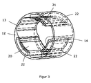
- FIG. 3 shows the sleeve 12 in a perspective view.
- the same components bear the same reference numbers.
- the sleeve 12 has a closed circular cylindrical outer surface without recesses or projections. This design ensures that the sleeve 12 can not be blocked by approximately fitting fragments of defective gear parts of the servo drive with respect to the steering housing, not shown, surrounding the ball nut.
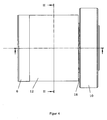
- FIG. 4 finally shows a side view according to the illustration of FIG. 1 but without cut.
- the line II - II marks the position of the cut in Fig. 2 is shown.
- the pulley 15 is not mounted in this illustration. It can be seen that the assembly consisting of ball nut with the circular cylindrical flange portion 6 and the sleeve 12 has a perfectly smooth outer peripheral surface, which is free of any recesses or projections. Even the gap 18 between the sleeve 12 and the rolling bearing 10 is rotationally symmetrical, so that also here penetrating components can not be wedged relative to the outside housing housing. It is with this type
Landscapes
- Engineering & Computer Science (AREA)
- General Engineering & Computer Science (AREA)
- Mechanical Engineering (AREA)
- Chemical & Material Sciences (AREA)
- Combustion & Propulsion (AREA)
- Transportation (AREA)
- Power Steering Mechanism (AREA)
- Transmission Devices (AREA)
Priority Applications (1)
| Application Number | Priority Date | Filing Date | Title |
|---|---|---|---|
| PL11790870T PL2649347T3 (pl) | 2010-12-10 | 2011-11-16 | Mechanizm z gwintem tocznym |
Applications Claiming Priority (2)
| Application Number | Priority Date | Filing Date | Title |
|---|---|---|---|
| DE102010054134A DE102010054134B3 (de) | 2010-12-10 | 2010-12-10 | Kugelgewindetrieb |
| PCT/EP2011/005765 WO2012076114A1 (de) | 2010-12-10 | 2011-11-16 | Kugelgewindetrieb |
Publications (2)
| Publication Number | Publication Date |
|---|---|
| EP2649347A1 EP2649347A1 (de) | 2013-10-16 |
| EP2649347B1 true EP2649347B1 (de) | 2014-04-09 |
Family
ID=45093672
Family Applications (1)
| Application Number | Title | Priority Date | Filing Date |
|---|---|---|---|
| EP11790870.7A Not-in-force EP2649347B1 (de) | 2010-12-10 | 2011-11-16 | Kugelgewindetrieb |
Country Status (6)
| Country | Link |
|---|---|
| US (1) | US8857283B2 (pl) |
| EP (1) | EP2649347B1 (pl) |
| CN (1) | CN103261741B (pl) |
| DE (1) | DE102010054134B3 (pl) |
| PL (1) | PL2649347T3 (pl) |
| WO (1) | WO2012076114A1 (pl) |
Families Citing this family (18)
| Publication number | Priority date | Publication date | Assignee | Title |
|---|---|---|---|---|
| KR101450326B1 (ko) | 2011-08-31 | 2014-10-21 | 주식회사 만도 | 벨트식 전동장치 및 이를 구비한 랙구동형 동력 보조 조향장치 |
| KR101454505B1 (ko) * | 2011-11-17 | 2014-10-28 | 주식회사 만도 | 랙구동형 동력 보조 조향장치 |
| US9637164B2 (en) | 2012-09-28 | 2017-05-02 | Steering Solutions Ip Holding Corporation | Nylon resin driven pulley |
| DE102013010704A1 (de) * | 2013-06-27 | 2014-12-31 | Thyssenkrupp Presta Ag | Kugelrückführung mit Drall |
| DE102014007866B4 (de) | 2014-06-03 | 2016-05-04 | Thyssenkrupp Presta Ag | Kunststoffhülse zur Absicherung einer Kugelumlenkung und zur Zentrierung einer Wellfeder und einer Passscheibe in einem Lenkgetriebe |
| US10730545B2 (en) * | 2015-02-03 | 2020-08-04 | Jtekt Corporation | Steering apparatus |
| DE102015211657B3 (de) * | 2015-06-24 | 2016-06-09 | Zf Friedrichshafen Ag | Riemenrad und Anordnung des Riemenrades auf einer Spindelmutter |
| DE102015013648B4 (de) | 2015-10-22 | 2025-11-13 | Thyssenkrupp Ag | Kugelrückführung mit axial montierbarer Befestigungshülse |
| EP3184387A1 (de) | 2015-12-22 | 2017-06-28 | CW Bearing GmbH | Elektromechanische feststellbremse mit kugelgewindetrieb und kugelrückführung sowie die verwendung eines kugelgewindetriebs mit kugelrückführung |
| JP6639280B2 (ja) * | 2016-03-11 | 2020-02-05 | 日立オートモティブシステムズ株式会社 | パワーステアリング装置 |
| PL3401571T3 (pl) * | 2017-05-11 | 2021-12-06 | Sfs Intec Holding Ag | Mechanizm śrubowo-toczny |
| DE102019208409A1 (de) * | 2019-06-08 | 2020-12-10 | Robert Bosch Gmbh | Lenksystem für ein Kraftfahrzeug |
| DE102019120812A1 (de) | 2019-08-01 | 2021-02-04 | Schaeffler Technologies AG & Co. KG | Verfahren zum Herstellen einer Gewindemutter eines Gewindetriebes, insbesondere Kugelgewindemutter eines Kugelgewindetriebes |
| DE102019120813A1 (de) * | 2019-08-01 | 2021-02-04 | Schaeffler Technologies AG & Co. KG | Verfahren zum Herstellen einer Gewindemutter eines Gewindetriebes, insbesondere Kugelgewindemutter eines Kugelgewindetriebes |
| CN110792744A (zh) * | 2019-12-04 | 2020-02-14 | 江苏启尖丝杠制造有限公司 | 齿条运动复合型滚珠丝杠副 |
| KR20220120823A (ko) * | 2021-02-24 | 2022-08-31 | 주식회사 만도 | 랙구동형 동력 보조 조향장치 |
| DE102023203807A1 (de) * | 2023-04-25 | 2024-10-31 | Zf Active Safety And Electronics Us Llc | Lenkgetriebe mit einem Kugelgewindetrieb sowie Lenksystem mit dem Lenkgetriebe |
| DE102023204853A1 (de) * | 2023-05-25 | 2024-11-28 | Zf Active Safety And Electronics Us Llc | Lenkgetriebe mit einem Kugelgewindetrieb sowie Lenksystem mit dem Lenkgetriebe |
Family Cites Families (13)
| Publication number | Priority date | Publication date | Assignee | Title |
|---|---|---|---|---|
| GB2370023B (en) * | 2000-07-21 | 2004-03-10 | Nsk Ltd | Electrically driven power steering apparatus |
| DE10056275B4 (de) * | 2000-11-14 | 2009-06-04 | Schaeffler Kg | Kugelgewindetrieb |
| KR100723814B1 (ko) * | 2002-07-12 | 2007-05-31 | 한라공조주식회사 | 동력전달장치 |
| US20060048592A1 (en) * | 2004-09-09 | 2006-03-09 | Ung Tom T | Damping nut for screw-driven mechanism |
| DE102004055423A1 (de) * | 2004-11-17 | 2006-05-24 | Schaeffler Kg | Kugelgewindetrieb |
| DE102004058963A1 (de) | 2004-12-08 | 2006-06-14 | Schaeffler Kg | Zahnriemenscheibe |
| DE102005023274B4 (de) * | 2005-05-20 | 2018-12-27 | Schaeffler Technologies AG & Co. KG | Wälzkörpergewindetrieb |
| EP1801460B1 (de) * | 2005-12-21 | 2010-04-14 | LuK Lamellen und Kupplungsbau Beteiligungs KG | Antriebseinheit mit einem inneren Antriebselement und einem äusseren Antriebselement |
| DE102006051639A1 (de) * | 2006-11-02 | 2008-05-08 | Schaeffler Kg | Kugelgewindetrieb |
| DE102006053244A1 (de) * | 2006-11-11 | 2008-05-15 | Schaeffler Kg | Kugelgewindetrieb |
| DE102007026605B4 (de) * | 2007-06-08 | 2019-01-24 | Schaeffler Technologies AG & Co. KG | Verfahren zur Herstellung eines Kugelgewindetriebes |
| DE102007049114B4 (de) | 2007-10-12 | 2018-02-15 | Volkswagen Ag | Zahnriemenrad einer elektromechanischen Lenkung mit Kugelgewindemutter |
| CN101629593B (zh) * | 2009-07-28 | 2011-05-11 | 西安东风仪表厂 | 滚珠丝杠副的柔性连接装置 |
-
2010
- 2010-12-10 DE DE102010054134A patent/DE102010054134B3/de not_active Expired - Fee Related
-
2011
- 2011-11-16 US US13/991,723 patent/US8857283B2/en active Active
- 2011-11-16 WO PCT/EP2011/005765 patent/WO2012076114A1/de not_active Ceased
- 2011-11-16 PL PL11790870T patent/PL2649347T3/pl unknown
- 2011-11-16 EP EP11790870.7A patent/EP2649347B1/de not_active Not-in-force
- 2011-11-16 CN CN201180059636.8A patent/CN103261741B/zh not_active Expired - Fee Related
Also Published As
| Publication number | Publication date |
|---|---|
| CN103261741A (zh) | 2013-08-21 |
| CN103261741B (zh) | 2016-05-18 |
| WO2012076114A1 (de) | 2012-06-14 |
| EP2649347A1 (de) | 2013-10-16 |
| PL2649347T3 (pl) | 2014-09-30 |
| US20130247701A1 (en) | 2013-09-26 |
| DE102010054134B3 (de) | 2012-04-12 |
| US8857283B2 (en) | 2014-10-14 |
Similar Documents
| Publication | Publication Date | Title |
|---|---|---|
| DE102010054134B3 (de) | Kugelgewindetrieb | |
| EP1992842B1 (de) | Getriebe für eine Verstelleinrichtung, insbesondere eine Kfz-Verstelleinrichtung, mit Spielausgleich | |
| EP1987270B1 (de) | Spindelantrieb, insbesondere zum verstellen eines beweglichen teils im kraftfahrzeug und verfahren zur herstellung dieses spindelantriebs | |
| DE102010021536B4 (de) | Spindelantrieb | |
| EP1103411B2 (de) | Verstellvorrichtung für einen Fahrzeugsitz mit einer Spindel und einer zugeordneten Spindelmutter | |
| EP3235679B1 (de) | Getriebe für eine verstelleinrichtung in fahrzeugen zum verstellen zweier zueinander verstellbarer fahrzeugteile | |
| EP2951053A1 (de) | Spindelgetriebe für eine verstellvorrichtung in einem kraftfahrzeug sowie fahrzeugsitz | |
| DE102007030445A1 (de) | Stellantrieb für ein Kraftfahrzeug, insbesondere eines Kraftfahrzeugsitzes | |
| EP3010781B1 (de) | Spielausgleich für eine ritzellagerung | |
| EP2234862A2 (de) | Elektrische servolenkung | |
| EP2233381A1 (de) | Kostengünstiges Zahnstangenlenkgetriebe | |
| EP3152095B1 (de) | Kunststoffhülse zur absicherung einer kugelumlenkung und zur zentrierung einer wellfeder und einer passscheibe in einem lenkgetriebe | |
| EP1659298B1 (de) | Linearantrieb | |
| DE2808884A1 (de) | Verstellbarer, insbesondere in einem fahrzeug, vorzugsweise kraftwagen, anzuordnender sitz | |
| EP1537346A1 (de) | Anpressvorrichtung | |
| DE102017211461B4 (de) | Lenkgetriebe | |
| EP2741949B1 (de) | Zahnstangenlenkgetriebe | |
| DE112015005904B4 (de) | Gurtschlossbringer | |
| EP4043319A1 (de) | Lenksystem für ein kraftfahrzeug und verfahren zum montieren eines lenksystems für ein kraftfahrzeug | |
| DE102015013648B4 (de) | Kugelrückführung mit axial montierbarer Befestigungshülse | |
| DE102015016469B4 (de) | Gurtschlossbringer | |
| EP0994553A1 (de) | Elektromotorischer Möbelantrieb | |
| DE20209787U1 (de) | Elektromotorischer Möbelantrieb | |
| DE102012107857A1 (de) | Lagerbuchse, insbesondere für einen Fahrzeugsitz | |
| DE19959004C1 (de) | Lenksäule für ein Kraftfahrzeug |
Legal Events
| Date | Code | Title | Description |
|---|---|---|---|
| PUAI | Public reference made under article 153(3) epc to a published international application that has entered the european phase |
Free format text: ORIGINAL CODE: 0009012 |
|
| 17P | Request for examination filed |
Effective date: 20130624 |
|
| AK | Designated contracting states |
Kind code of ref document: A1 Designated state(s): AL AT BE BG CH CY CZ DE DK EE ES FI FR GB GR HR HU IE IS IT LI LT LU LV MC MK MT NL NO PL PT RO RS SE SI SK SM TR |
|
| GRAP | Despatch of communication of intention to grant a patent |
Free format text: ORIGINAL CODE: EPIDOSNIGR1 |
|
| DAX | Request for extension of the european patent (deleted) | ||
| INTG | Intention to grant announced |
Effective date: 20131120 |
|
| GRAS | Grant fee paid |
Free format text: ORIGINAL CODE: EPIDOSNIGR3 |
|
| GRAA | (expected) grant |
Free format text: ORIGINAL CODE: 0009210 |
|
| AK | Designated contracting states |
Kind code of ref document: B1 Designated state(s): AL AT BE BG CH CY CZ DE DK EE ES FI FR GB GR HR HU IE IS IT LI LT LU LV MC MK MT NL NO PL PT RO RS SE SI SK SM TR |
|
| REG | Reference to a national code |
Ref country code: GB Ref legal event code: FG4D Free format text: NOT ENGLISH |
|
| REG | Reference to a national code |
Ref country code: AT Ref legal event code: REF Ref document number: 661525 Country of ref document: AT Kind code of ref document: T Effective date: 20140415 Ref country code: CH Ref legal event code: EP |
|
| REG | Reference to a national code |
Ref country code: IE Ref legal event code: FG4D Free format text: LANGUAGE OF EP DOCUMENT: GERMAN |
|
| REG | Reference to a national code |
Ref country code: DE Ref legal event code: R096 Ref document number: 502011002697 Country of ref document: DE Effective date: 20140522 |
|
| REG | Reference to a national code |
Ref country code: NL Ref legal event code: VDEP Effective date: 20140409 |
|
| REG | Reference to a national code |
Ref country code: LT Ref legal event code: MG4D |
|
| REG | Reference to a national code |
Ref country code: PL Ref legal event code: T3 |
|
| PG25 | Lapsed in a contracting state [announced via postgrant information from national office to epo] |
Ref country code: IS Free format text: LAPSE BECAUSE OF FAILURE TO SUBMIT A TRANSLATION OF THE DESCRIPTION OR TO PAY THE FEE WITHIN THE PRESCRIBED TIME-LIMIT Effective date: 20140809 Ref country code: GR Free format text: LAPSE BECAUSE OF FAILURE TO SUBMIT A TRANSLATION OF THE DESCRIPTION OR TO PAY THE FEE WITHIN THE PRESCRIBED TIME-LIMIT Effective date: 20140710 Ref country code: BG Free format text: LAPSE BECAUSE OF FAILURE TO SUBMIT A TRANSLATION OF THE DESCRIPTION OR TO PAY THE FEE WITHIN THE PRESCRIBED TIME-LIMIT Effective date: 20140709 Ref country code: FI Free format text: LAPSE BECAUSE OF FAILURE TO SUBMIT A TRANSLATION OF THE DESCRIPTION OR TO PAY THE FEE WITHIN THE PRESCRIBED TIME-LIMIT Effective date: 20140409 Ref country code: NO Free format text: LAPSE BECAUSE OF FAILURE TO SUBMIT A TRANSLATION OF THE DESCRIPTION OR TO PAY THE FEE WITHIN THE PRESCRIBED TIME-LIMIT Effective date: 20140709 Ref country code: LT Free format text: LAPSE BECAUSE OF FAILURE TO SUBMIT A TRANSLATION OF THE DESCRIPTION OR TO PAY THE FEE WITHIN THE PRESCRIBED TIME-LIMIT Effective date: 20140409 Ref country code: NL Free format text: LAPSE BECAUSE OF FAILURE TO SUBMIT A TRANSLATION OF THE DESCRIPTION OR TO PAY THE FEE WITHIN THE PRESCRIBED TIME-LIMIT Effective date: 20140409 |
|
| PG25 | Lapsed in a contracting state [announced via postgrant information from national office to epo] |
Ref country code: LV Free format text: LAPSE BECAUSE OF FAILURE TO SUBMIT A TRANSLATION OF THE DESCRIPTION OR TO PAY THE FEE WITHIN THE PRESCRIBED TIME-LIMIT Effective date: 20140409 Ref country code: ES Free format text: LAPSE BECAUSE OF FAILURE TO SUBMIT A TRANSLATION OF THE DESCRIPTION OR TO PAY THE FEE WITHIN THE PRESCRIBED TIME-LIMIT Effective date: 20140409 Ref country code: SE Free format text: LAPSE BECAUSE OF FAILURE TO SUBMIT A TRANSLATION OF THE DESCRIPTION OR TO PAY THE FEE WITHIN THE PRESCRIBED TIME-LIMIT Effective date: 20140409 Ref country code: RS Free format text: LAPSE BECAUSE OF FAILURE TO SUBMIT A TRANSLATION OF THE DESCRIPTION OR TO PAY THE FEE WITHIN THE PRESCRIBED TIME-LIMIT Effective date: 20140409 Ref country code: HR Free format text: LAPSE BECAUSE OF FAILURE TO SUBMIT A TRANSLATION OF THE DESCRIPTION OR TO PAY THE FEE WITHIN THE PRESCRIBED TIME-LIMIT Effective date: 20140409 |
|
| PG25 | Lapsed in a contracting state [announced via postgrant information from national office to epo] |
Ref country code: PT Free format text: LAPSE BECAUSE OF FAILURE TO SUBMIT A TRANSLATION OF THE DESCRIPTION OR TO PAY THE FEE WITHIN THE PRESCRIBED TIME-LIMIT Effective date: 20140811 |
|
| REG | Reference to a national code |
Ref country code: DE Ref legal event code: R097 Ref document number: 502011002697 Country of ref document: DE |
|
| PG25 | Lapsed in a contracting state [announced via postgrant information from national office to epo] |
Ref country code: RO Free format text: LAPSE BECAUSE OF FAILURE TO SUBMIT A TRANSLATION OF THE DESCRIPTION OR TO PAY THE FEE WITHIN THE PRESCRIBED TIME-LIMIT Effective date: 20140409 Ref country code: EE Free format text: LAPSE BECAUSE OF FAILURE TO SUBMIT A TRANSLATION OF THE DESCRIPTION OR TO PAY THE FEE WITHIN THE PRESCRIBED TIME-LIMIT Effective date: 20140409 Ref country code: DK Free format text: LAPSE BECAUSE OF FAILURE TO SUBMIT A TRANSLATION OF THE DESCRIPTION OR TO PAY THE FEE WITHIN THE PRESCRIBED TIME-LIMIT Effective date: 20140409 Ref country code: SK Free format text: LAPSE BECAUSE OF FAILURE TO SUBMIT A TRANSLATION OF THE DESCRIPTION OR TO PAY THE FEE WITHIN THE PRESCRIBED TIME-LIMIT Effective date: 20140409 |
|
| PLBE | No opposition filed within time limit |
Free format text: ORIGINAL CODE: 0009261 |
|
| STAA | Information on the status of an ep patent application or granted ep patent |
Free format text: STATUS: NO OPPOSITION FILED WITHIN TIME LIMIT |
|
| 26N | No opposition filed |
Effective date: 20150112 |
|
| PGFP | Annual fee paid to national office [announced via postgrant information from national office to epo] |
Ref country code: IT Payment date: 20141130 Year of fee payment: 4 |
|
| REG | Reference to a national code |
Ref country code: DE Ref legal event code: R097 Ref document number: 502011002697 Country of ref document: DE Effective date: 20150112 |
|
| PG25 | Lapsed in a contracting state [announced via postgrant information from national office to epo] |
Ref country code: BE Free format text: LAPSE BECAUSE OF NON-PAYMENT OF DUE FEES Effective date: 20141130 Ref country code: LU Free format text: LAPSE BECAUSE OF FAILURE TO SUBMIT A TRANSLATION OF THE DESCRIPTION OR TO PAY THE FEE WITHIN THE PRESCRIBED TIME-LIMIT Effective date: 20141116 Ref country code: MC Free format text: LAPSE BECAUSE OF FAILURE TO SUBMIT A TRANSLATION OF THE DESCRIPTION OR TO PAY THE FEE WITHIN THE PRESCRIBED TIME-LIMIT Effective date: 20140409 |
|
| REG | Reference to a national code |
Ref country code: CH Ref legal event code: PL |
|
| PG25 | Lapsed in a contracting state [announced via postgrant information from national office to epo] |
Ref country code: LI Free format text: LAPSE BECAUSE OF NON-PAYMENT OF DUE FEES Effective date: 20141130 Ref country code: SI Free format text: LAPSE BECAUSE OF FAILURE TO SUBMIT A TRANSLATION OF THE DESCRIPTION OR TO PAY THE FEE WITHIN THE PRESCRIBED TIME-LIMIT Effective date: 20140409 Ref country code: CH Free format text: LAPSE BECAUSE OF NON-PAYMENT OF DUE FEES Effective date: 20141130 |
|
| REG | Reference to a national code |
Ref country code: IE Ref legal event code: MM4A |
|
| PG25 | Lapsed in a contracting state [announced via postgrant information from national office to epo] |
Ref country code: IE Free format text: LAPSE BECAUSE OF NON-PAYMENT OF DUE FEES Effective date: 20141116 |
|
| REG | Reference to a national code |
Ref country code: FR Ref legal event code: PLFP Year of fee payment: 5 |
|
| PG25 | Lapsed in a contracting state [announced via postgrant information from national office to epo] |
Ref country code: SM Free format text: LAPSE BECAUSE OF FAILURE TO SUBMIT A TRANSLATION OF THE DESCRIPTION OR TO PAY THE FEE WITHIN THE PRESCRIBED TIME-LIMIT Effective date: 20140409 |
|
| PG25 | Lapsed in a contracting state [announced via postgrant information from national office to epo] |
Ref country code: CY Free format text: LAPSE BECAUSE OF FAILURE TO SUBMIT A TRANSLATION OF THE DESCRIPTION OR TO PAY THE FEE WITHIN THE PRESCRIBED TIME-LIMIT Effective date: 20140409 |
|
| PG25 | Lapsed in a contracting state [announced via postgrant information from national office to epo] |
Ref country code: TR Free format text: LAPSE BECAUSE OF FAILURE TO SUBMIT A TRANSLATION OF THE DESCRIPTION OR TO PAY THE FEE WITHIN THE PRESCRIBED TIME-LIMIT Effective date: 20140409 Ref country code: MT Free format text: LAPSE BECAUSE OF FAILURE TO SUBMIT A TRANSLATION OF THE DESCRIPTION OR TO PAY THE FEE WITHIN THE PRESCRIBED TIME-LIMIT Effective date: 20140409 Ref country code: IT Free format text: LAPSE BECAUSE OF NON-PAYMENT OF DUE FEES Effective date: 20151116 Ref country code: HU Free format text: LAPSE BECAUSE OF FAILURE TO SUBMIT A TRANSLATION OF THE DESCRIPTION OR TO PAY THE FEE WITHIN THE PRESCRIBED TIME-LIMIT; INVALID AB INITIO Effective date: 20111116 |
|
| REG | Reference to a national code |
Ref country code: FR Ref legal event code: PLFP Year of fee payment: 6 |
|
| REG | Reference to a national code |
Ref country code: FR Ref legal event code: PLFP Year of fee payment: 7 |
|
| REG | Reference to a national code |
Ref country code: AT Ref legal event code: MM01 Ref document number: 661525 Country of ref document: AT Kind code of ref document: T Effective date: 20161116 |
|
| PG25 | Lapsed in a contracting state [announced via postgrant information from national office to epo] |
Ref country code: AT Free format text: LAPSE BECAUSE OF NON-PAYMENT OF DUE FEES Effective date: 20161116 |
|
| PG25 | Lapsed in a contracting state [announced via postgrant information from national office to epo] |
Ref country code: MK Free format text: LAPSE BECAUSE OF FAILURE TO SUBMIT A TRANSLATION OF THE DESCRIPTION OR TO PAY THE FEE WITHIN THE PRESCRIBED TIME-LIMIT Effective date: 20140409 |
|
| PG25 | Lapsed in a contracting state [announced via postgrant information from national office to epo] |
Ref country code: AL Free format text: LAPSE BECAUSE OF FAILURE TO SUBMIT A TRANSLATION OF THE DESCRIPTION OR TO PAY THE FEE WITHIN THE PRESCRIBED TIME-LIMIT Effective date: 20140409 |
|
| REG | Reference to a national code |
Ref country code: DE Ref legal event code: R081 Ref document number: 502011002697 Country of ref document: DE Owner name: THYSSENKRUPP PRESTA AKTIENGESELLSCHAFT, LI Free format text: FORMER OWNER: THYSSENKRUPP PRESTA AG, ESCHEN, LI |
|
| PGFP | Annual fee paid to national office [announced via postgrant information from national office to epo] |
Ref country code: CZ Payment date: 20211116 Year of fee payment: 11 |
|
| PGFP | Annual fee paid to national office [announced via postgrant information from national office to epo] |
Ref country code: PL Payment date: 20211104 Year of fee payment: 11 |
|
| REG | Reference to a national code |
Ref country code: DE Ref legal event code: R084 Ref document number: 502011002697 Country of ref document: DE |
|
| PGFP | Annual fee paid to national office [announced via postgrant information from national office to epo] |
Ref country code: GB Payment date: 20221125 Year of fee payment: 12 Ref country code: FR Payment date: 20221129 Year of fee payment: 12 Ref country code: DE Payment date: 20221123 Year of fee payment: 12 |
|
| PG25 | Lapsed in a contracting state [announced via postgrant information from national office to epo] |
Ref country code: CZ Free format text: LAPSE BECAUSE OF NON-PAYMENT OF DUE FEES Effective date: 20221116 |
|
| PG25 | Lapsed in a contracting state [announced via postgrant information from national office to epo] |
Ref country code: PL Free format text: LAPSE BECAUSE OF NON-PAYMENT OF DUE FEES Effective date: 20221116 |
|
| REG | Reference to a national code |
Ref country code: DE Ref legal event code: R119 Ref document number: 502011002697 Country of ref document: DE |
|
| GBPC | Gb: european patent ceased through non-payment of renewal fee |
Effective date: 20231116 |
|
| PG25 | Lapsed in a contracting state [announced via postgrant information from national office to epo] |
Ref country code: DE Free format text: LAPSE BECAUSE OF NON-PAYMENT OF DUE FEES Effective date: 20240601 |
|
| PG25 | Lapsed in a contracting state [announced via postgrant information from national office to epo] |
Ref country code: GB Free format text: LAPSE BECAUSE OF NON-PAYMENT OF DUE FEES Effective date: 20231116 |
|
| PG25 | Lapsed in a contracting state [announced via postgrant information from national office to epo] |
Ref country code: FR Free format text: LAPSE BECAUSE OF NON-PAYMENT OF DUE FEES Effective date: 20231130 |
|
| PG25 | Lapsed in a contracting state [announced via postgrant information from national office to epo] |
Ref country code: GB Free format text: LAPSE BECAUSE OF NON-PAYMENT OF DUE FEES Effective date: 20231116 Ref country code: FR Free format text: LAPSE BECAUSE OF NON-PAYMENT OF DUE FEES Effective date: 20231130 Ref country code: DE Free format text: LAPSE BECAUSE OF NON-PAYMENT OF DUE FEES Effective date: 20240601 |