EP2648870B1 - Cutting tool for machining a workpiece - Google Patents
Cutting tool for machining a workpiece Download PDFInfo
- Publication number
- EP2648870B1 EP2648870B1 EP11787689.6A EP11787689A EP2648870B1 EP 2648870 B1 EP2648870 B1 EP 2648870B1 EP 11787689 A EP11787689 A EP 11787689A EP 2648870 B1 EP2648870 B1 EP 2648870B1
- Authority
- EP
- European Patent Office
- Prior art keywords
- interface
- cutting tool
- cutting
- holder
- previous
- Prior art date
- Legal status (The legal status is an assumption and is not a legal conclusion. Google has not performed a legal analysis and makes no representation as to the accuracy of the status listed.)
- Active
Links
- 238000005520 cutting process Methods 0.000 title claims description 87
- 238000003754 machining Methods 0.000 title claims description 4
- 125000006850 spacer group Chemical group 0.000 claims description 45
- 230000008878 coupling Effects 0.000 claims description 14
- 238000010168 coupling process Methods 0.000 claims description 14
- 238000005859 coupling reaction Methods 0.000 claims description 14
- 239000002826 coolant Substances 0.000 claims description 4
- 241000047428 Halter Species 0.000 description 3
- 238000004519 manufacturing process Methods 0.000 description 3
- 230000000295 complement effect Effects 0.000 description 2
- 239000002131 composite material Substances 0.000 description 2
- 238000009826 distribution Methods 0.000 description 2
- 208000027418 Wounds and injury Diseases 0.000 description 1
- 230000005540 biological transmission Effects 0.000 description 1
- 230000006378 damage Effects 0.000 description 1
- 230000007547 defect Effects 0.000 description 1
- 238000005553 drilling Methods 0.000 description 1
- 208000014674 injury Diseases 0.000 description 1
- 238000002955 isolation Methods 0.000 description 1
- 238000005555 metalworking Methods 0.000 description 1
- 238000003801 milling Methods 0.000 description 1
- 230000007704 transition Effects 0.000 description 1
Images


Classifications
-
- B—PERFORMING OPERATIONS; TRANSPORTING
- B23—MACHINE TOOLS; METAL-WORKING NOT OTHERWISE PROVIDED FOR
- B23C—MILLING
- B23C5/00—Milling-cutters
- B23C5/16—Milling-cutters characterised by physical features other than shape
- B23C5/20—Milling-cutters characterised by physical features other than shape with removable cutter bits or teeth or cutting inserts
- B23C5/22—Securing arrangements for bits or teeth or cutting inserts
- B23C5/2295—Securing arrangements for bits or teeth or cutting inserts the cutting elements being clamped simultaneously
-
- B—PERFORMING OPERATIONS; TRANSPORTING
- B23—MACHINE TOOLS; METAL-WORKING NOT OTHERWISE PROVIDED FOR
- B23C—MILLING
- B23C5/00—Milling-cutters
- B23C5/006—Details of the milling cutter body
-
- B—PERFORMING OPERATIONS; TRANSPORTING
- B23—MACHINE TOOLS; METAL-WORKING NOT OTHERWISE PROVIDED FOR
- B23C—MILLING
- B23C5/00—Milling-cutters
- B23C5/02—Milling-cutters characterised by the shape of the cutter
- B23C5/10—Shank-type cutters, i.e. with an integral shaft
- B23C5/109—Shank-type cutters, i.e. with an integral shaft with removable cutting inserts
-
- B—PERFORMING OPERATIONS; TRANSPORTING
- B23—MACHINE TOOLS; METAL-WORKING NOT OTHERWISE PROVIDED FOR
- B23C—MILLING
- B23C5/00—Milling-cutters
- B23C5/28—Features relating to lubricating or cooling
-
- B—PERFORMING OPERATIONS; TRANSPORTING
- B23—MACHINE TOOLS; METAL-WORKING NOT OTHERWISE PROVIDED FOR
- B23C—MILLING
- B23C2210/00—Details of milling cutters
- B23C2210/02—Connections between the shanks and detachable cutting heads
-
- B—PERFORMING OPERATIONS; TRANSPORTING
- B23—MACHINE TOOLS; METAL-WORKING NOT OTHERWISE PROVIDED FOR
- B23C—MILLING
- B23C2210/00—Details of milling cutters
- B23C2210/03—Cutting heads comprised of different material than the shank irrespective of whether the head is detachable from the shank
-
- B—PERFORMING OPERATIONS; TRANSPORTING
- B23—MACHINE TOOLS; METAL-WORKING NOT OTHERWISE PROVIDED FOR
- B23C—MILLING
- B23C2210/00—Details of milling cutters
- B23C2210/24—Overall form of the milling cutter
- B23C2210/244—Milling cutters comprised of disc-shaped modules or multiple disc-like cutters
-
- B—PERFORMING OPERATIONS; TRANSPORTING
- B23—MACHINE TOOLS; METAL-WORKING NOT OTHERWISE PROVIDED FOR
- B23C—MILLING
- B23C2265/00—Details of general geometric configurations
- B23C2265/32—Polygonal
-
- B—PERFORMING OPERATIONS; TRANSPORTING
- B23—MACHINE TOOLS; METAL-WORKING NOT OTHERWISE PROVIDED FOR
- B23C—MILLING
- B23C5/00—Milling-cutters
- B23C5/02—Milling-cutters characterised by the shape of the cutter
- B23C5/08—Disc-type cutters
-
- B—PERFORMING OPERATIONS; TRANSPORTING
- B23—MACHINE TOOLS; METAL-WORKING NOT OTHERWISE PROVIDED FOR
- B23C—MILLING
- B23C5/00—Milling-cutters
- B23C5/16—Milling-cutters characterised by physical features other than shape
- B23C5/20—Milling-cutters characterised by physical features other than shape with removable cutter bits or teeth or cutting inserts
- B23C5/22—Securing arrangements for bits or teeth or cutting inserts
-
- Y—GENERAL TAGGING OF NEW TECHNOLOGICAL DEVELOPMENTS; GENERAL TAGGING OF CROSS-SECTIONAL TECHNOLOGIES SPANNING OVER SEVERAL SECTIONS OF THE IPC; TECHNICAL SUBJECTS COVERED BY FORMER USPC CROSS-REFERENCE ART COLLECTIONS [XRACs] AND DIGESTS
- Y10—TECHNICAL SUBJECTS COVERED BY FORMER USPC
- Y10T—TECHNICAL SUBJECTS COVERED BY FORMER US CLASSIFICATION
- Y10T407/00—Cutters, for shaping
- Y10T407/14—Cutters, for shaping with means to apply fluid to cutting tool
-
- Y—GENERAL TAGGING OF NEW TECHNOLOGICAL DEVELOPMENTS; GENERAL TAGGING OF CROSS-SECTIONAL TECHNOLOGIES SPANNING OVER SEVERAL SECTIONS OF THE IPC; TECHNICAL SUBJECTS COVERED BY FORMER USPC CROSS-REFERENCE ART COLLECTIONS [XRACs] AND DIGESTS
- Y10—TECHNICAL SUBJECTS COVERED BY FORMER USPC
- Y10T—TECHNICAL SUBJECTS COVERED BY FORMER US CLASSIFICATION
- Y10T407/00—Cutters, for shaping
- Y10T407/19—Rotary cutting tool
- Y10T407/1902—Gang
-
- Y—GENERAL TAGGING OF NEW TECHNOLOGICAL DEVELOPMENTS; GENERAL TAGGING OF CROSS-SECTIONAL TECHNOLOGIES SPANNING OVER SEVERAL SECTIONS OF THE IPC; TECHNICAL SUBJECTS COVERED BY FORMER USPC CROSS-REFERENCE ART COLLECTIONS [XRACs] AND DIGESTS
- Y10—TECHNICAL SUBJECTS COVERED BY FORMER USPC
- Y10T—TECHNICAL SUBJECTS COVERED BY FORMER US CLASSIFICATION
- Y10T407/00—Cutters, for shaping
- Y10T407/22—Cutters, for shaping including holder having seat for inserted tool
- Y10T407/2208—Plural simultaneously usable separable tools in common seat or common clamp actuator for plural simultaneously usable tools
-
- Y—GENERAL TAGGING OF NEW TECHNOLOGICAL DEVELOPMENTS; GENERAL TAGGING OF CROSS-SECTIONAL TECHNOLOGIES SPANNING OVER SEVERAL SECTIONS OF THE IPC; TECHNICAL SUBJECTS COVERED BY FORMER USPC CROSS-REFERENCE ART COLLECTIONS [XRACs] AND DIGESTS
- Y10—TECHNICAL SUBJECTS COVERED BY FORMER USPC
- Y10T—TECHNICAL SUBJECTS COVERED BY FORMER US CLASSIFICATION
- Y10T407/00—Cutters, for shaping
- Y10T407/23—Cutters, for shaping including tool having plural alternatively usable cutting edges
-
- Y—GENERAL TAGGING OF NEW TECHNOLOGICAL DEVELOPMENTS; GENERAL TAGGING OF CROSS-SECTIONAL TECHNOLOGIES SPANNING OVER SEVERAL SECTIONS OF THE IPC; TECHNICAL SUBJECTS COVERED BY FORMER USPC CROSS-REFERENCE ART COLLECTIONS [XRACs] AND DIGESTS
- Y10—TECHNICAL SUBJECTS COVERED BY FORMER USPC
- Y10T—TECHNICAL SUBJECTS COVERED BY FORMER US CLASSIFICATION
- Y10T407/00—Cutters, for shaping
- Y10T407/28—Miscellaneous
Definitions
- the invention relates to a cutting tool for machining a workpiece.
- a cutting tool and a cutting plate for a cutting tool are from the DE 102 22 446 A1 known. Such tools are used, for example, for milling chamfers. In particular in metalworking deburring or chamfering of a surface is of great importance. When chamfering, the sharp edges of workpieces are bevelled, which reduces the risk of injury. Different inserts can be used to create chamfers. A frequent task when creating bevels is that a chamfer is to be created both on the top and on the underside of a workpiece. Since conventional cutting tools generally have only one cutting insert, the chamfers on the top and bottom of the workpiece must hitherto be produced in two working steps.
- a drilling tool according to the preamble of claim 1 is made WO 2006/136338 A1 known. From the WO 2006/136338 A1 an interface of a tool system is known, in which at least two parts of the tool system are connectable to each other, wherein the end face of the one part bears against the end face of the other part at least partially.
- the end faces have radially extending depressions and elevations, which are designed to be complementary, so that the resulting contour of one end face in the assembled state of the interface can engage in that of the other.
- the cut parts are characterized by the fact that the recesses and elevations from the inside outwards - preferably continuously - wider. Further tool interfaces are from the DE 102 22 446 A1 and the US 5,607,263 A known.
- the invention has for its object to provide a cutting tool with which two or more chamfers, grooves and / or joints can be made simultaneously.
- the invention has for its object to provide a spacer and a cutting plate for such a cutting tool.
- the spacer With its two oppositely arranged interfaces, it is possible that the torque from the holder via the first cutting plate and spacer can be passed to the second insert and the second insert can be performed with exactly fixed distance to the first insert and coaxial with the first insert.
- This makes it possible to produce two or more chamfers (and / or joints and / or grooves) at precisely defined intervals in one operation.
- chamfers with different distances can be produced by using spacers of different length.
- Another advantage is that more than two chamfers can be produced in one operation by coupling several inserts and spacer elements.
- the spacer element can be assumed and only the second cutting plate can be attached directly to the holder.
- the fourth interface has at least one contact surface, wherein only radial contact surfaces are located in an axial region.
- the first and the fifth interface are formed substantially the same.
- conventional cutting plates which can be placed directly on the holder, can be coupled to the spacer and thus can be used in a cutting tool according to the invention as a second cutting plate.
- already known holders can be used in a cutting tool according to the invention.
- the interfaces do not have to be formed completely identical, but for the power transmission and the coupling to each other coupling components relevant elements of the interface, such as the number, location and orientation of ribs and thus corresponding joints.
- the first interface does not correspond to the fifth interface.
- the first and fifth interface can be adapted to special requirements of the first and second insert.
- the second insert could be a three-edged insert and the first insert could be a five-edged insert. These inserts could require different corresponding interfaces, which would be possible in this embodiment.
- the first and fifth interface are attached to each other twisted around the holder longitudinal axis.
- the cutting elements of the first and second cutting plate are arranged radially offset from one another.
- a circumferentially offset (rotated) positioning of the cutting elements of the first and the second cutting plate has the advantage that a better distribution of force is achieved. This can be achieved in that the two cutting plates have a different offset relative to the interfaces.
- the cutting elements may be positioned equidistant to the interfaces of the inserts, and the offset achieved by a radial orientation of the interfaces rotated with respect to each other.
- the holder bore has an internal thread
- the fastening element is a screw with a corresponding external thread and all holes are continuous.
- the cutting tool has exactly one spacer element. This has the advantage that the second cutting plate can be fastened relative to the first cutting plate with particularly high precision, since tolerances of several spacer elements do not add up.
- the cutting tool alternately has a plurality of spacer elements and a plurality of first cutting plates. This makes it possible that more than two inserts can be mounted with fixed distances to each other and thus more than two chamfers, joints and / or grooves can be generated simultaneously.
- the fifth interface of the spacer corresponds to the fourth interface, so that a plurality of spacer elements can be connected to each other. Similar to pluggable blocks so different distances can be realized by simply coupling spacer elements. By combination of spacer elements of different lengths can thus be realized by simply juxtaposing the spacer elements arbitrary distances of the cutting plates.
- the third interface on three radial surfaces which form angles of 60 ° to each other. This allows a particularly stable attachment.
- the fastening element has an inner bore for the supply of coolant and / or for the passage of a fastening element.
- radially mounted openings in the fastener may be used to supply coolant to various inserts.
- the invention also relates to an insert according to claim 12 and a spacer element according to claim 13.
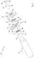
- Fig. 1 and 2 show the cutting tool 10, which has a holder 12, a first cutting plate 14, a spacer element 16, a second cutting plate 18 and a fastening element 20.
- the holder 12 here comprises a holder base part 22 and a Auflötteil 24, but may in principle be integrally formed.
- the Auflötteil 24 has a plurality of holes 26 for supplying coolant.
- a first interface 28 is mounted frontally.
- the axially parallel holder bore 30 extends axially through the holder.
- an internal thread 32 is attached, see the fastening element 20, which here is a screw and has an external thread 34, can be screwed to the holder 12.
- the first interface 28 is the same in this example as the fifth interface 50, which in Fig. 7 is shown in detail.
- the first cutting plate 14 has, on the side facing the holder, a second interface 36 corresponding to the first interface. On the side facing away from the holder there is a third interface 38. In the radial direction, cutting elements 40 are distributed over the circumference. In this embodiment, cutting plate is shown with six cutting elements, but the number can be chosen differently depending on the desired processing.
- the third interface 38 has three radially outwardly directed radial bearing surfaces 44 and an axial bearing surface 45. The radial bearing surfaces 44 are at an angle of 60 ° to each other.
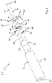
- the fourth interface 46 has three inwardly directed radial bearing surfaces 48 running in the direction of the holder longitudinal axis.
- the inwardly directed radial contact surfaces 48 are also at an angle of 60 ° to each other.
- a cutting tool 10 can be formed for simultaneously performing a plurality of cutting operations (e.g., making more than two chamfers, joints, and / or grooves).
- the fourth and fifth interface 46, 50 of the spacer element can also be configured corresponding to one another.
- several such spacers be coupled to each other and larger distances between the first and second cutting plate 14, 18 can be realized.
- the sixth interface 52 On the holder-facing side of the second cutting plate 18 is the sixth interface 52. Distributed in the circumferential direction are located on the second cutting plate 18 cutting elements 40 '. These are arranged offset relative to the cutting elements 40 of the first cutting plate. This is achieved in that the fifth interface 50 (corresponding to the first interface 28) is correspondingly circumferentially rotated in comparison to the first interface 28.
- a contact surface 54 On the side facing away from the holder is a contact surface 54, to which the head 56 of the fastener 20 can be applied.
- the screw 20 On the screw (the fastener) 20 is an external thread 34.
- the screw 20 is so long that it passes through the coaxial with the holder bore holes 30 of the first cutting plate 14, spacer 16 and second cutting plate 18 and the internal thread 32 of the holder bore 30 can be screwed.
- a tool engagement 58 e.g. for a Torx key, provided.
- FIG. 3 and FIG. 4 show two side views of a cutting tool 10 according to the invention in the assembled state.
- the components already explained are here the grooves 66 of the first interface 28 and the second interface 36 as well as the complementary shaped ribs 78 of the second and sixth interfaces 36, 52.
- First and fifth interface 28, 50 are the same design, as well as the corresponding second and sixth interface 28, 52.
- the first interface 28 is arranged but slightly rotated relative to the fifth interface 50 to the holder longitudinal axis. This results in that the second and sixth interface 36, 52 and thus first and second cutting plate 14, 18 are arranged rotated to each other about the holder longitudinal axis.
- Fig. 5 shows a plan view of the cutting tool 10 from the workpiece-facing side. It can be seen that the cutting elements 40, 40 'of the first and second cutting plates 14, 18 have an offset from each other.
- the staggered arrangement of the cutting elements 40, 40 ' is a preferred embodiment, since there is a more uniform force distribution during processing.
- the first and the fifth interface 28, 50 are not rotated to each other, and thus that also the cutting elements of the first and second cutting plate 14, 18 have no offset.
- Fig. 6 shows the holder-facing side of a spacer element 16 according to the invention shown in the figure above fourth interface 46 has three inwardly directed radial contact surfaces 48 (only one of which is visible in the figure). The three radial contact surfaces 48 are connected to each other via three rounded corner pieces 60.
- the fourth interface 46 has an inner axial surface 62 and an outer axial surface 64. The support of a coupled to the fourth interface 46 further interface takes place via the outer axial surface 64th
- the transition between the inward radial abutment surfaces 48 and the outer axial surface 64 is in the form of a chamfered surface (bevel) 76 which also extends along the circular corner piece 60.
- the chamfer 76 facilitates coupling to a corresponding interface, but is otherwise not essential to the interface features of the fifth interface.
- the spacer 16 may be shortened in length (e.g., abraded, turned, or sawn off) on the bracket-facing side in the axial region 74 without significantly altering the interface characteristics of the fourth interface 46.
- the axial extent of the axial region 74 depends on the axial extent of the region in which the interface has only radial surfaces.
- the third interface 38 corresponding to the fourth interface 46 has three axially projecting, outwardly directed radial contact surfaces 80 (shown in FIG Fig. 1 ).
- the height of these contact surfaces 80 in the axial direction is less than the height of the inwardly directed radial contact surfaces 48 of the fourth interface 46. In the mounted state, the inwardly directed contact surfaces 48 thus completely surround the outwardly directed contact surfaces 80.
- Fig. 7 shows the side facing away from the workpiece of the spacer element 16 according to the invention.
- the visible in the figure fifth interface 50 has three grooves 66, three side grooves 68 and three axial surfaces 82.
- Each groove 66 has inclined side surfaces 70, 72, wherein the side surfaces 72 are inclined steeper and are provided as a torque-engaging surfaces.
- An interface corresponding to the fifth interface 50 has three corresponding ribs 78 (shown in FIG Fig. 2 ).
- the axial surfaces 82 are not necessarily intended to abut with a corresponding surface of the sixth interface 52. Instead, the support regions are merely formed by partial surfaces on the side walls of the grooves 66 of the fifth interface 50. Between the axial surface 82 and an opposite axial surface 84 at the sixth interface 52 thus remains a small gap. This simplifies the production, because, in contrast to a full-surface contact with the axial surface 82, only the smaller support areas on the grooves 66 have to be made tightly tolerated. In other words, the accuracy of the coupling realized with the fifth and sixth interfaces 50, 52 is not disturbed by any surface defects possibly occurring outside the limited support areas, if such should be present on the axial surfaces 82 lying outside the support areas.
- the invention is an easy to manufacture and easy-to-use tool, with the double or multiple operations can be made with high accuracy in one operation.
- a new type of tool is being created, which offers a significant reduction in the workload involved in carrying out a number of, in particular, similar machining operations.
- the tool according to the invention can also be both a rotating and a stationary cutting tool.
Landscapes
- Engineering & Computer Science (AREA)
- Mechanical Engineering (AREA)
- Milling Processes (AREA)
Description
Die Erfindung betrifft ein Schneidwerkzeug zur spanenden Bearbeitung eines Werkstücks.The invention relates to a cutting tool for machining a workpiece.
Ein Schneidwerkzeug und eine Schneidplatte für ein Schneidwerkzeug sind aus der
Der Erfindung liegt die Aufgabe zugrunde, ein Schneidwerkzeug zu schaffen, mit dem zwei oder mehr Fasen, Nuten und/oder Fugen gleichzeitig hergestellt werden können. Außerdem liegt der Erfindung die Aufgabe zugrunde, ein Distanzelement und eine Schneidplatte für ein solches Schneidwerkzeug zu schaffen.The invention has for its object to provide a cutting tool with which two or more chamfers, grooves and / or joints can be made simultaneously. In addition, the invention has for its object to provide a spacer and a cutting plate for such a cutting tool.
Diese Aufgabe wird gelöst durch ein Schneidwerkzeug gemäß Anspruch 1 mit
- einem Halter mit einer achsparallelen Halterbohrung und einer ersten Schnittstelle am werkstückseitigen Ende zur Ankopplung einer Schneidplatte mit einer mit der ersten Schnittstelle korrespondierenden Schnittstelle,
- einer ersten Schneidplatte mit einer mit der ersten Schnittstelle korrespondierenden zweiten Schnittstelle zur Ankopplung an einer mit der zweiten Schnittstelle korrespondierenden Schnittstelle und mit einer gegenüberliegend angeordneten dritten Schnittstelle,
- einem Distanzelement mit einer mit der dritten Schnittstelle korrespondierenden vierten Schnittstelle zur Ankopplung an einer mit der vierten Schnittstelle korrespondierenden Schnittstelle und mit einer gegenüberliegend angeordneten fünften Schnittstelle,
- einer zweiten Schneidplatte mit einer mit der fünften Schnittstelle korrespondierenden sechsten Schnittstelle zur Ankopplung an einer mit der sechsten Schnittstelle korrespondierenden Schnittstelle,
- mindestens einem Befestigungselement zur Befestigung der Schneidplatten, des Distanzelements und des Halters miteinander, wobei die erste Schneidplatte, die zweite Schneidplatte und das Distanzelement in deren Längsrichtung jeweils eine zu der Halterbohrung koaxiale Bohrung zur Aufnahme des mindestens ersten Befestigungselements aufweisen, wobei die vierte Schnittstelle mindestens eine Anlagefläche aufweist, wobei sich in einem axialen Bereich nur radiale Anlageflächen befinden.
- a holder with an axis-parallel holder bore and a first interface at the workpiece-side end for coupling an insert to an interface corresponding to the first interface,
- a first cutting plate having a second interface corresponding to the first interface for coupling to an interface corresponding to the second interface and having an oppositely disposed third interface,
- a spacer element having a fourth interface corresponding to the third interface for coupling to an interface corresponding to the fourth interface and having an oppositely disposed fifth interface,
- a second cutting plate with a sixth interface corresponding to the fifth interface for coupling to an interface corresponding to the sixth interface,
- at least one fastening element for fastening the cutting plates, the spacer element and the holder with each other, wherein the first cutting plate, the second cutting plate and the spacer in the longitudinal direction each have a bore coaxial with the holder bore for receiving the at least first fastener, wherein the fourth interface at least one Has contact surface, with only radial contact surfaces are in an axial region.
Durch das Distanzelement mit seinen beiden gegenüberliegend angeordneten Schnittstellen ist es möglich, dass das Drehmoment vom Halter über erste Schneidplatte und Distanzelement an die zweite Schneidplatte weitergegeben werden kann und die zweite Schneidplatte mit exakt festgelegtem Abstand zur ersten Schneidplatte und koaxial zur ersten Schneidplatte geführt werden kann. Hiermit ist es also möglich, in einem Arbeitsgang zwei oder mehr Fasen (und/oder Fugen und/oder Nuten) in präzise festgelegten Abständen zu erzeugen. Es ist ferner ein Vorteil des erfindungsgemäßen Schneidwerkzeugs, dass durch Verwendung unterschiedlich langer Distanzelemente Fasen mit unterschiedlichen Abständen hergestellt werden können. Ein weiterer Vorteil ist, dass durch Kopplung mehrerer Schneidplatten und Distanzelemente auch mehr als zwei Fasen in einem Arbeitsgang hergestellt werden können. Ferner kann das Distanzelement angenommen und nur die zweite Schneidplatte direkt an dem Halter angebracht werden.By the spacer with its two oppositely arranged interfaces, it is possible that the torque from the holder via the first cutting plate and spacer can be passed to the second insert and the second insert can be performed with exactly fixed distance to the first insert and coaxial with the first insert. This makes it possible to produce two or more chamfers (and / or joints and / or grooves) at precisely defined intervals in one operation. It is also an advantage of the cutting tool according to the invention that chamfers with different distances can be produced by using spacers of different length. Another advantage is that more than two chamfers can be produced in one operation by coupling several inserts and spacer elements. Furthermore, the spacer element can be assumed and only the second cutting plate can be attached directly to the holder.
Erfingdungsgemäß weist die vierte Schnittstelle mindestens eine Anlagefläche auf, wobei sich in einem axialen Bereich nur radiale Anlageflächen befinden. Somit kann die Länge des Distanzelements verkürzt werden und die vierte Schnittstelle ist dennoch weiterhin zu der dritten Schnittstelle korrespondierend. Hierdurch ist es möglich, dass, auch wenn Distanzelemente in Serie nur mit bestimmten Längen hergestellt werden, die Distanzelemente individuell beispielsweise durch Abdrehen verkürzt werden können. Hierdurch sind beliebige Abstände zwischen den Schneidplatten realisierbar.According to the invention, the fourth interface has at least one contact surface, wherein only radial contact surfaces are located in an axial region. Thus, the length of the spacer can be shortened and the fourth interface is still corresponding to the third interface. This makes it possible that, even if spacer elements are produced in series only with certain lengths, the spacer elements can be shortened individually, for example by turning off. As a result, any distances between the cutting plates can be realized.
In einer bevorzugten Ausgestaltung der Erfindung sind die erste und die fünfte Schnittstelle im Wesentlichen gleich ausgebildet. Dadurch ist es möglich, dass herkömmliche Schneidplatten, die direkt auf den Halter aufgesetzt werden können, an das Distanzelement angekoppelt werden können und somit in einem erfindungsgemäßen Schneidwerkzeug auch als zweite Schneidplatte verwendet werden können. Ebenso können bereits bekannte Halter in einem erfindungsgemäßen Schneidwerkzeug verwendet werden. "Im Wesentlichen gleich" ist also so zu verstehen, dass die Schnittstellen nicht vollkommen identisch ausgebildet sein müssen, sondern die für die Kraftübertragung und die Kopplung der miteinander zu koppelnden Bauteile relevanten Elemente der Schnittstelle, wie etwa die Anzahl, Lage und Orientierung von Rippen und damit korrespondierenden Fugen.In a preferred embodiment of the invention, the first and the fifth interface are formed substantially the same. This makes it possible that conventional cutting plates, which can be placed directly on the holder, can be coupled to the spacer and thus can be used in a cutting tool according to the invention as a second cutting plate. Likewise, already known holders can be used in a cutting tool according to the invention. "Essentially the same" is thus to be understood that the interfaces do not have to be formed completely identical, but for the power transmission and the coupling to each other coupling components relevant elements of the interface, such as the number, location and orientation of ribs and thus corresponding joints.
Alternativ entspricht in einer weiteren Ausgestaltung die erste Schnittstelle nicht der fünften Schnittstelle. Hiermit ist es möglich, dass die erste und fünfte Schnittstelle an besondere Anforderungen der ersten und zweiten Schneidplatte angepasst werden können. Zum Beispiel könnte die zweite Schneidplatte ein dreischneidige Schneidplatte sein und die erste Schneidplatte eine fünfschneidige Schneidplatte. Diese Schneidplatten könnten unterschiedliche korrespondierende Schnittstellen erfordern, was in dieser Ausgestaltung ermöglicht wäre.Alternatively, in a further embodiment, the first interface does not correspond to the fifth interface. This makes it possible that the first and fifth interface can be adapted to special requirements of the first and second insert. For example, the second insert could be a three-edged insert and the first insert could be a five-edged insert. These inserts could require different corresponding interfaces, which would be possible in this embodiment.
In einer bevorzugten Ausgestaltung sind die erste und fünfte Schnittstelle zueinander um die Halterlängsachse verdreht angebracht. In dieser Ausgestaltung sind die Schneidelemente der ersten und zweiten Schneidplatte radial zueinander versetzt angeordnet.In a preferred embodiment, the first and fifth interface are attached to each other twisted around the holder longitudinal axis. In this embodiment, the cutting elements of the first and second cutting plate are arranged radially offset from one another.
Eine in Umfangsrichtung versetzte (verdrehte) Positionierung der Schneidelemente der ersten und der zweiten Schneidplatte hat den Vorteil, dass eine bessere Kraftverteilung erreicht wird. Dies kann dadurch erreicht werden, dass die beiden Schneidplatten relativ zu den Schnittstellen einen unterschiedlichen Versatz aufweisen. Alternativ können, wie in dieser Ausgestaltung bevorzugt, die Schneidelemente relativ zu den Schnittstellen der Schneidplatten gleich positioniert sein, und der Versatz durch eine zueinander verdrehte radiale Ausrichtung der Schnittstellen erreicht werden.A circumferentially offset (rotated) positioning of the cutting elements of the first and the second cutting plate has the advantage that a better distribution of force is achieved. This can be achieved in that the two cutting plates have a different offset relative to the interfaces. Alternatively, as preferred in this embodiment, the cutting elements may be positioned equidistant to the interfaces of the inserts, and the offset achieved by a radial orientation of the interfaces rotated with respect to each other.
In einer bevorzugten Ausgestaltung der Erfindung weist die Halterbohrung ein Innengewinde auf, das Befestigungselement ist eine Schraube mit einem korrespondierenden Außengewinde und alle Bohrungen sind durchgängig. Dadurch können die erste Schneidplatte, die zweite Schneidplatte und das Distanzelement mit einer Schraube besonders einfach und stabil befestigt werden. Ebenso ist ein einfacher Austausch des Distanzelements möglich.In a preferred embodiment of the invention, the holder bore has an internal thread, the fastening element is a screw with a corresponding external thread and all holes are continuous. As a result, the first insert, the second insert and the spacer can be fastened particularly easily and stably with a screw. Likewise, a simple replacement of the spacer element is possible.
In einer weiteren Ausgestaltung weist das Schneidwerkzeug genau ein Distanzelement auf. Dies hat den Vorteil, dass die zweite Schneidplatte relativ zu der ersten Schneidplatte mit besonders hoher Präzision befestigt werden kann, da sich Toleranzen von mehreren Distanzelementen nicht aufaddieren.In a further embodiment, the cutting tool has exactly one spacer element. This has the advantage that the second cutting plate can be fastened relative to the first cutting plate with particularly high precision, since tolerances of several spacer elements do not add up.
In einer weiteren Ausgestaltung weist das Schneidwerkzeug abwechselnd mehrere Distanzelemente und mehrere erste Schneidplatten auf. Hierdurch ist es möglich, dass mehr als zwei Schneidplatten mit festgelegten Abständen zueinander montiert werden können und somit auch mehr als zwei Fasen, Fugen und/oder Nuten gleichzeitig erzeugt werden können.In a further embodiment, the cutting tool alternately has a plurality of spacer elements and a plurality of first cutting plates. This makes it possible that more than two inserts can be mounted with fixed distances to each other and thus more than two chamfers, joints and / or grooves can be generated simultaneously.
In einer weiteren Ausgestaltung korrespondiert die fünfte Schnittstelle des Distanzelements mit der vierten Schnittstelle, so dass mehrere Distanzelemente aneinandergekoppelt werden können. Ähnlich wie bei steckbaren Bausteinen können also durch einfaches Ankoppeln von Distanzelementen unterschiedliche Abstände realisiert werden. Durch Kombination von Distanzelementen unterschiedlicher Länge können somit durch einfaches Aneinanderstecken der Distanzelemente beliebige Abstände der Schneidplatten realisiert werden.In a further embodiment, the fifth interface of the spacer corresponds to the fourth interface, so that a plurality of spacer elements can be connected to each other. Similar to pluggable blocks so different distances can be realized by simply coupling spacer elements. By combination of spacer elements of different lengths can thus be realized by simply juxtaposing the spacer elements arbitrary distances of the cutting plates.
In einer bevorzugten Ausgestaltung weist die dritte Schnittstelle drei radiale Flächen auf, die zueinander Winkel von 60° bilden. Dies ermöglicht eine besonders stabile Befestigung.In a preferred embodiment, the third interface on three radial surfaces, which form angles of 60 ° to each other. This allows a particularly stable attachment.
In einer weiteren Ausgestaltung weist das Befestigungselement eine Innenbohrung zur Zuführung von Kühlmittel und/oder zur Durchführung eines Befestigungselementes auf. Vorteilhafterweise können radial angebrachte Öffnungen im Befestigungselement dazu verwendet werden, um Kühlmittel zu verschiedenen Schneidplatten zuzuführen.In a further embodiment, the fastening element has an inner bore for the supply of coolant and / or for the passage of a fastening element. Advantageously, radially mounted openings in the fastener may be used to supply coolant to various inserts.
Gegenstand der Erfindung ist auch eine Schneidplatte nach Anspruch 12 sowie ein Distanzelement nach Anspruch 13.The invention also relates to an insert according to
Es versteht sich, dass die vorstehend genannten und die nachstehend noch zu erläuternden Merkmale nicht nur in der jeweils angegebenen Kombination, sondern auch in anderen Kombinationen oder in Alleinstellung verwendbar sind, ohne den Rahmen der vorliegenden Erfindung zu verlassen.It is understood that the features mentioned above and those yet to be explained below can be used not only in the particular combination given, but also in other combinations or in isolation, without departing from the scope of the present invention.
Ausführungsbeispiele der Erfindung sind in der Zeichnung dargestellt und werden in der nachfolgenden Beschreibung näher erläutert. Es zeigen:
- Fig. 1
- eine Explosionsdarstellung eines erfindungsgemäßen Schneidwerkzeugs mit Halter, erster Schneidplatte, Distanzelement, zweiter Schneidplatte und Befestigungselement,
- Fig. 2
- eine Explosionsdarstellung ähnlich
Fig. 1 aus einer anderen Perspektive, - Fig. 3
- eine Darstellung eines zusammengesetzten erfindungsgemäßen Schneidwerkzeugs,
- Fig. 4
- eine Darstellung eines zusammengesetzten erfindungsgemäßen Schneidwerkzeugs aus einer anderen Perspektive,
- Fig. 5
- eine Darstellung eines zusammengesetzten erfindungsgemäßen Schneidwerkzeugs von der dem Werkstück zugewandten Seite aus gesehen,
- Fig. 6
- eine Ansicht der dem Werkstück zugewandten Seite eines erfindungsgemäßen Distanzelements, und
- Fig. 7
- eine Ansicht der dem Werkstück abgewandte Seite eines erfindungsgemäßen Distanzelements.
- Fig. 1
- an exploded view of a cutting tool according to the invention with holder, first cutting plate, spacer element, second cutting plate and fastener,
- Fig. 2
- an exploded view similar
Fig. 1 from a different perspective, - Fig. 3
- a representation of a composite cutting tool according to the invention,
- Fig. 4
- a representation of a composite cutting tool according to the invention from another perspective,
- Fig. 5
- an illustration of an assembled cutting tool according to the invention seen from the workpiece side facing,
- Fig. 6
- a view of the workpiece facing side of a spacer element according to the invention, and
- Fig. 7
- a view of the workpiece remote from the side of a spacer element according to the invention.
Die erste Schneidplatte 14 weist auf der dem Halter zugewandten Seite eine zur ersten Schnittstelle korrespondierende zweite Schnittstelle 36 auf. Auf der dem Halter abgewandten Seite befindet sich eine dritte Schnittstelle 38. In radialer Richtung sind über den Umfang verteilt Schneidelemente 40 angebracht. In dieser Ausgestaltung ist Schneidplatte mit sechs Schneidelementen gezeigt, die Anzahl kann aber je nach gewünschter Bearbeitung unterschiedlich gewählt werden. Durch die Schneidplatte 14 verläuft eine mit der Halterbohrung 30 koaxiale Bohrung 42. Die dritte Schnittstelle 38 weist drei radial nach außen gerichtete radiale Anlageflächen 44 und eine axiale Anlagefläche 45 auf. Die radialen Anlagenflächen 44 stehen zueinander in einem Winkel von 60°.The
An dem Distanzelement 16 befindet sich auf der dem Halter zugewandten Seite eine vierte Schnittstelle 46. Die vierte Schnittstelle 46 weist drei nach innen gerichtete radiale in Richtung der Halterlängsachse verlaufende Anlageflächen 48 auf. Die nach innen gerichteten radialen Anlageflächen 48 stehen ebenfalls in einem Winkel von 60° zueinander. An der dem Halter abgewandten Seite des Distanzelements befindet sich eine fünfte Schnittstelle 50. Da die zweite Schnittstelle 36 mit der fünften Schnittstelle 50 korrespondiert, können eine weitere Schneidplatte vom Typ der ersten Schneidplatte und ein weiteres Distanzelement zwischen dem Distanzelement 16 und der zweiten Schneidplatte 18 eingefügt werden. Durch Hinzufügen von weiteren ersten Schneidplatten und Distanzelementen kann somit ein Schneidwerkzeug 10 zum gleichzeitigen Durchführen von mehreren Schneidbearbeitungen (z.B. Erstellen von mehr als zwei Fasen, Fugen und/oder Nuten) gebildet werden.The
Abweichend von dem in den Figuren gezeigten Schneidwerkzeug können die vierte und fünfte Schnittstelle 46, 50 des Distanzelements auch zueinander korrespondierend ausgestaltet werden. Somit können mehrere solche Distanzelemente aneinander gekoppelt werden und größere Abstände zwischen erster und zweiter Schneidplatte 14, 18 realisiert werden.Notwithstanding the cutting tool shown in the figures, the fourth and
Auf der dem Halter zugewandten Seite der zweiten Schneidplatte 18 befindet sich die sechste Schnittstelle 52. In Umfangrichtung verteilt befinden sich an der zweiten Schneidplatte 18 Schneidelemente 40'. Diese sind relativ zu den Schneidelementen 40 der ersten Schneidplatte versetzt angeordnet. Dies ist dadurch erreicht, dass die fünfte Schnittstelle 50 (die der ersten Schnittstelle 28 entspricht) im Vergleich zur ersten Schnittstelle 28 entsprechend in Umfangsrichtung verdreht ist. An der dem Halter abgewandten Seite befindet sich eine Anlagefläche 54, an die der Kopf 56 des Befestigungselements 20 angelegt werden kann.On the holder-facing side of the
An der Schraube (dem Befestigungselement) 20 befindet sich ein Außengewinde 34. Die Schraube 20 ist so lang, dass es durch die mit der Halterbohrung 30 koaxialen Bohrungen von erster Schneidplatte 14, Distanzelement 16 und zweiter Schneidplatte 18 geführt und mit dem Innengewinde 32 der Halterbohrung 30 verschraubt werden kann. Am werkstückseitigen Ende der Schraube 20 ist hierfür ein Werkzeugeingriff 58, z.B. für einen Torx-Schlüssel, vorgesehen.On the screw (the fastener) 20 is an
Der Übergang zwischen den nach innen gerichteten radialen Anlageflächen 48 und der äußeren axialen Fläche 64 ist ausgebildet in Form einer abgeschrägten Fläche (Fase) 76, die sich auch entlang des runden Eckstücks 60 erstreckt. Die Fase 76 erleichtert das Ankoppeln mit einer korrespondierenden Schnittstelle, ist aber ansonsten nicht wesentlich für die Schnittstelleneigenschaften der fünften Schnittstelle.The transition between the inward radial abutment surfaces 48 and the outer
Das Distanzelement 16 kann an der dem Halter zugewandten Seite in dem axialen Bereich 74 in der Länge verkürzt (z.B. abgerieben, abgedreht oder abgesägt) werden, ohne dass sich dadurch die Schnittstelleneigenschaften der vierten Schnittstelle 46 wesentlich verändern würden. Die axiale Ausdehnung des axialen Bereichs 74 hängt dabei von der axialen Ausdehnung des Bereichs ab, in dem die Schnittstelle nur radiale Flächen aufweist.The
Die zur vierten Schnittstelle 46 korrespondierende dritte Schnittstelle 38 weist drei axial vorstehende, nach außen gerichtete radiale Anlageflächen 80 auf (gezeigt in
Die axialen Flächen 82 sind nicht notwendigerweise zur Anlage mit einer korrespondierenden Fläche der sechsten Schnittstelle 52 gedacht. Die Tragbereiche werden stattdessen lediglich durch Teilflächen an den Seitenwänden der Nuten 66 der fünften Schnittstelle 50 gebildet. Zwischen axialer Fläche 82 und einer gegenüber liegenden axialen Fläche 84 an der sechsten Schnittstelle 52 bleibt damit ein kleiner Spalt. Dies vereinfacht die Herstellung, weil, im Unterschied zu einer vollflächigen Anlage an der axialen Fläche 82, lediglich die kleineren Tragbereiche an den Nuten 66 eng toleriert hergestellt werden müssen. Mit anderen Worten, die Genauigkeit der mit der fünften und sechsten Schnittstelle 50, 52 realisierten Ankopplung wird durch außerhalb der begrenzten Tragbereiche ggf. auftretende Oberflächenfehler nicht gestört, falls solche an den außerhalb der Tragbereiche liegenden, axialen Flächen 82 vorhanden sein sollten. Entsprechende Überlegungen gelten für die gegenüberliegende axiale Fläche 84 an der sechsten Schnittstelle 52. Diese Erwägungen sind in der Produktion von besonderer Bedeutung, weil die die Hartmetall-Schneidplatten bildenden, gesinterten Rohlinge aufwändig zu bearbeiten sind. Die hier dargelegten Überlegungen zu fünfter und sechster Schnittstelle 50, 52 gelten entsprechend z.B. für erste und zweite Schnittstelle 28, 36.The
Die Erfindung stellt ein einfach herzustellendes und leicht zu bedienendes Werkzeug dar, mit dem Doppel- oder Mehrfachbearbeitungen mit hoher Genauigkeit in einem Arbeitsgang angefertigt werden können. Mit nur zwei neuen Bauteilen (einer ersten Schneidplatte mit zwei Schnittstellen und einem Distanzelement) entsteht ein neuartiges Werkzeug, das eine bedeutende Arbeitserleichterung beim der Vornahme von mehreren, insbesondere gleichartigen Bearbeitungsvorgängen bietet. Mit dem vorgeschlagenen Werkzeug kann dabei ein einziges Werkstücks bearbeitet werden. Es ist aber auch geeignet, mehrere Werkstücke gleichzeitig zu bearbeiten, indem diese im Paket gestapelt bearbeitet werden. Bei dem erfindungsgemäßen Werkzeug kann es sich ferner sowohl um ein rotierendes als auch ein stehendes spanabhebendes Werkzeug handeln.The invention is an easy to manufacture and easy-to-use tool, with the double or multiple operations can be made with high accuracy in one operation. With only two new components (a first insert with two interfaces and a spacer element) A new type of tool is being created, which offers a significant reduction in the workload involved in carrying out a number of, in particular, similar machining operations. With the proposed tool while a single workpiece can be edited. But it is also suitable to work on several workpieces at the same time by these are processed stacked in the package. The tool according to the invention can also be both a rotating and a stationary cutting tool.
Claims (10)
- A cutting tool (10) for machining a workpiece, comprising:- a holder (12) having an axially parallel holder bore (30) and a first interface (28) for the coupling of a cutting insert (14) having an interface (36) corresponding to the first interface (28),- a first cutting insert (14) having a second interface (36), corresponding to the first interface (28), for the coupling to an interface (28) corresponding to the second interface (36) and having an oppositely disposed third interface (38),- a spacer element (16) having a fourth interface (46), corresponding to the third interface (38), for the coupling to an interface (38) corresponding to the fourth interface (46), and having an oppositely disposed fifth interface (50),- a second cutting insert (18) having a sixth interface (52), corresponding to the fifth interface (50), for the coupling to an interface (50) corresponding to the sixth interface (52), and- at least one fastening element (20) for fastening together the cutting inserts (14, 18), the spacer element (16) and the holder (12), wherein the first cutting insert (14), the second cutting insert (18) and the spacer element (16) respectively have in their longitudinal direction a bore (42), coaxial to the holder bore (30), for the reception of the at least first fastening element (20)characterized in that the fourth interface (46) has at least one contact surface, wherein only radial contact surfaces (44) are present in an axial region.
- The cutting tool (10) as claimed in claim 1, wherein the first interface (28) and the fifth interface (50) are configured to be substantially the same.
- The cutting tool (10) as claimed in one of the previous claims, wherein the first (28) and fifth interface (50) are placed twisted relative to each other about the holder longitudinal axis.
- The cutting tool (10) as claimed in one of the previous claims, wherein the holder bore (30) has an internal thread (32), and the fastening element (20) is a screw having a corresponding external thread (34), and all bores (42) are through bores.
- The cutting tool (10) as claimed in one of the previous claims, having a plurality of alternating spacer elements (16) and first cutting inserts (14).
- The cutting tool (10) as claimed in one of the previous claims, wherein the fifth interface (50) of the spacer element (16) corresponds to the fourth interface (46), so that a plurality of spacer elements (16) can be coupled to one another.
- The cutting tool (10) as claimed in one of the previous claims, wherein the third interface (38) has three radial contact surfaces (44), which run at an angle of 60° to one another.
- The cutting tool (10) as claimed in one of the previous claims, wherein the fastening element (20) has an inner bore for the supply of coolant and/or for the lead-through of a fastening element.
- The cutting tool (10) as claimed in one of the previous claims, wherein the first interface (28) has three radially aligned grooves (66) and the second interface (36) has three ribs (78) corresponding thereto.
- The cutting tool (10) as claimed in claim 9, wherein each groove (66) has a first and a second inclined side face (70, 72), the second side face (72) being more steeply inclined than the first inclined side face (70).
Applications Claiming Priority (2)
| Application Number | Priority Date | Filing Date | Title |
|---|---|---|---|
| DE102010054392A DE102010054392A1 (en) | 2010-12-07 | 2010-12-07 | Cutting tool for machining a tool |
| PCT/EP2011/070811 WO2012076338A1 (en) | 2010-12-07 | 2011-11-23 | Cutting tool for machining a tool |
Publications (2)
| Publication Number | Publication Date |
|---|---|
| EP2648870A1 EP2648870A1 (en) | 2013-10-16 |
| EP2648870B1 true EP2648870B1 (en) | 2017-05-31 |
Family
ID=45023846
Family Applications (1)
| Application Number | Title | Priority Date | Filing Date |
|---|---|---|---|
| EP11787689.6A Active EP2648870B1 (en) | 2010-12-07 | 2011-11-23 | Cutting tool for machining a workpiece |
Country Status (4)
| Country | Link |
|---|---|
| US (1) | US9352402B2 (en) |
| EP (1) | EP2648870B1 (en) |
| DE (1) | DE102010054392A1 (en) |
| WO (1) | WO2012076338A1 (en) |
Families Citing this family (23)
| Publication number | Priority date | Publication date | Assignee | Title |
|---|---|---|---|---|
| CN202356732U (en) * | 2011-12-11 | 2012-08-01 | 富泰华精密电子(郑州)有限公司 | Slotting cutter |
| US9865434B2 (en) * | 2013-06-05 | 2018-01-09 | Applied Materials, Inc. | Rare-earth oxide based erosion resistant coatings for semiconductor application |
| EP2818268B1 (en) * | 2013-06-26 | 2017-05-10 | VARGUS Ltd. | Cutting insert and a tool holder with a seat for cutting insert |
| DE102013011726A1 (en) * | 2013-07-12 | 2015-01-29 | Bayerische Motorenwerke Aktiengesellschaft | Method for processing a running surface of a cylinder of an internal combustion engine |
| CN103551645A (en) * | 2013-10-24 | 2014-02-05 | 无锡雨田精密工具有限公司 | Circular cutter of packing machine |
| DE102014207502B4 (en) * | 2014-04-17 | 2022-11-24 | Kennametal Inc. | rotary tool and tool head |
| EP2954968B1 (en) * | 2014-06-13 | 2021-01-20 | Walter Ag | Thread milling cutter |
| CN104139201B (en) * | 2014-07-31 | 2016-05-18 | 浙江双飞无油轴承股份有限公司 | Magnetic chuck auto-feed sheet material slotter |
| WO2016203519A1 (en) * | 2015-06-15 | 2016-12-22 | オーエスジー株式会社 | Insert-type tool and thread mill |
| WO2016203521A1 (en) * | 2015-06-15 | 2016-12-22 | オーエスジー株式会社 | Reamer |
| US10328503B2 (en) * | 2015-06-15 | 2019-06-25 | Osg Corporation | T-slot cutter |
| US10343224B2 (en) | 2016-04-04 | 2019-07-09 | Ford Motor Company | Interpolated milling tools and methods |
| DE102016109670A1 (en) * | 2016-05-25 | 2017-11-30 | Hartmetall-Werkzeugfabrik Paul Horn Gmbh | Cutting plate and tool for machining |
| EP3308890A4 (en) * | 2016-08-03 | 2019-03-20 | OPM Laboratory Co., Ltd. | Cutting tool and apparatus for producing three-dimensional additive manufacturing product |
| JP6867171B2 (en) * | 2017-01-12 | 2021-04-28 | 株式会社Subaru | Manufacturing method for boring tools and honeycomb parts |
| DE102017202394A1 (en) * | 2017-02-15 | 2018-08-16 | Hoffmann GmbH Qualitätswerkzeuge | Device for processing cylinder walls of internal combustion engines |
| DE102017120188A1 (en) * | 2017-09-01 | 2019-03-07 | Kennametal Inc. | Tangential cutting insert, cutting tool with a Tangentialschneidsatz and method for producing a Tangentialschneideinsatzes |
| PL3501701T3 (en) * | 2017-12-22 | 2021-01-11 | Ceratizit Austria Gesellschaft M.B.H. | Tool system and method for turning |
| EP3536427B1 (en) * | 2018-03-08 | 2022-08-17 | AB Sandvik Coromant | Turning tool and turning method for cnc-machines |
| US20200254545A1 (en) * | 2019-02-08 | 2020-08-13 | Kennametal Inc. | One-piece reamer cutting discs and tool bodies |
| TWI778459B (en) | 2020-11-27 | 2022-09-21 | 張新添 | Combined chamfering tool |
| DE102021112412A1 (en) | 2021-05-12 | 2022-11-17 | Erwin Quarder Systemtechnik Gmbh | Metal heat sink and method for manufacturing the same |
| EP4347203A1 (en) * | 2021-05-25 | 2024-04-10 | C.M.T. Utensili S.P.A. | Rotatable tool-assembly for processing wooden panels and the like |
Family Cites Families (25)
| Publication number | Priority date | Publication date | Assignee | Title |
|---|---|---|---|---|
| US349475A (en) * | 1886-09-21 | Shaping-tool | ||
| US53496A (en) * | 1866-03-27 | Improvement in milling-tools | ||
| US1725299A (en) * | 1927-03-03 | 1929-08-20 | Rowland O Pickin | Well reamer |
| US2282596A (en) * | 1939-11-13 | 1942-05-12 | Edward T Wise | Replaceable bit for drill rods |
| US2369273A (en) * | 1943-03-23 | 1945-02-13 | Harding F Bakewell | Rotary cutting tool |
| GB1206205A (en) * | 1967-08-30 | 1970-09-23 | Reimers Getriebe Ag | Quick-set toolholder |
| US3986543A (en) * | 1975-07-21 | 1976-10-19 | Kimball International, Inc. | Rotary cutter knife |
| DE2630047C3 (en) * | 1976-07-03 | 1981-04-23 | Gebr. Heller Maschinenfabrik GmbH, 7440 Nürtingen | Milling tool for machining crankshafts and crankshaft milling machine for using this milling tool |
| JPH08507003A (en) * | 1993-04-14 | 1996-07-30 | ツェトル.ゲゼルシャフト.ミット.ベシュレンクテル.ハフツング.ツェーエヌツェー.プレツィシオンズ−ウント.ゾンデルウエルクツオイグ | Milling tools |
| US5309962A (en) * | 1993-05-13 | 1994-05-10 | Vermont American Corporation | Multiple saw blade adjustable dado cutter assembly including a cam assembly and nestable dado blades |
| DE10009721A1 (en) * | 2000-03-01 | 2001-09-06 | Komet Stahlhalter Werkzeuge | Machine reamer with axially protending head designs head as variable cutter plate with extension having three equi-spaced wedge faces forming truncated pyramid and matched by plate seat bevel faces. |
| US6568442B1 (en) * | 2001-11-28 | 2003-05-27 | Joseph Anthony Meugniot | Router bit for floorboard |
| SE524063C2 (en) * | 2002-01-29 | 2004-06-22 | Sandvik Ab | Tool coupling for rotating tools where the female part of the coupling has a triangular cross section |
| DE10222445A1 (en) * | 2002-05-22 | 2003-12-04 | Horn P Hartmetall Werkzeugfab | Cutting plate for a processing tool and holder for such a cutting plate |
| DE10222446A1 (en) | 2002-05-22 | 2003-12-04 | Horn P Hartmetall Werkzeugfab | Machining tool, in particular milling tool |
| DE50308700D1 (en) * | 2003-11-06 | 2008-01-10 | Urma Ag | Machine friction tool, replaceable head and shaft |
| DE102004023710B4 (en) * | 2004-05-11 | 2014-07-10 | Komet Group Gmbh | Machine tool with interchangeable cutting plate and interchangeable cutting plate for a machine tool |
| US7325471B2 (en) * | 2004-09-07 | 2008-02-05 | Kennametal Inc. | Toolholder and cutting insert for a toolholder assembly |
| DE102005034426A1 (en) * | 2005-06-20 | 2006-12-28 | MAPAL Fabrik für Präzisionswerkzeuge Dr. Kress KG | Link interface for two components forming part of a precision machine tool have intermeshing peaks and troughs of changing width |
| WO2006136338A1 (en) * | 2005-06-20 | 2006-12-28 | MAPAL Fabrik für Präzisionswerkzeuge Dr. Kress KG | Interface of a tool system |
| IL181834A (en) * | 2006-04-02 | 2011-04-28 | Iscar Ltd | Cutting head and adaptor |
| DE102007001864A1 (en) | 2007-01-12 | 2008-07-17 | Kennametal Inc. | milling |
| DE102008015582B4 (en) * | 2008-03-18 | 2010-04-08 | MAPAL Fabrik für Präzisionswerkzeuge Dr. Kress KG | rolling mills |
| SE535941C2 (en) * | 2011-06-20 | 2013-02-26 | Sandvik Intellectual Property | Milling tools for hobbing and segments for this |
| DE102011055210B4 (en) * | 2011-11-10 | 2020-05-07 | Mimatic Gmbh | Threading tool |
-
2010
- 2010-12-07 DE DE102010054392A patent/DE102010054392A1/en not_active Withdrawn
-
2011
- 2011-11-23 EP EP11787689.6A patent/EP2648870B1/en active Active
- 2011-11-23 WO PCT/EP2011/070811 patent/WO2012076338A1/en active Application Filing
-
2013
- 2013-06-07 US US13/912,265 patent/US9352402B2/en active Active
Also Published As
| Publication number | Publication date |
|---|---|
| US20130272807A1 (en) | 2013-10-17 |
| US9352402B2 (en) | 2016-05-31 |
| DE102010054392A1 (en) | 2012-06-14 |
| WO2012076338A1 (en) | 2012-06-14 |
| EP2648870A1 (en) | 2013-10-16 |
Similar Documents
| Publication | Publication Date | Title |
|---|---|---|
| EP2648870B1 (en) | Cutting tool for machining a workpiece | |
| EP0734299B1 (en) | Milling and boring tool | |
| EP2318166B1 (en) | Tool for machining a work piece | |
| EP1321210B1 (en) | Chamfering tool | |
| EP3341149B1 (en) | Cutting insert, tool holder and tool | |
| DE102011055210B4 (en) | Threading tool | |
| EP3129180A1 (en) | Rotary tool, in particular a drill, and cutting head for a rotary tool of this type | |
| WO2013037458A1 (en) | Clamping system and base, collet chuck and rotary tool therefor and method for mounting the rotary tool in the clamping system | |
| WO2003097282A1 (en) | Machining tool, especially a milling tool | |
| EP1646470A1 (en) | Interface between two parts of a tool system | |
| WO2006136338A1 (en) | Interface of a tool system | |
| EP3071355B1 (en) | Conical countersink | |
| EP1738849B1 (en) | End Mill | |
| EP2091681B2 (en) | Cutting insert for a turning tool and machining process with this cutting insert | |
| EP1715975B1 (en) | High-speed milling cutter | |
| EP2464479B1 (en) | Milling tool, in particular a thread milling tool | |
| DE102014209135B3 (en) | Tool head and rotary tool with such | |
| EP2480363A1 (en) | Cutting tool with exchangeable cutting insert | |
| DE102005034426A1 (en) | Link interface for two components forming part of a precision machine tool have intermeshing peaks and troughs of changing width | |
| DE19948891A1 (en) | Steamed tool | |
| DE102004008167B4 (en) | Boring Tool | |
| DE3130229C2 (en) | Multi-edge tool | |
| DE19548199A1 (en) | Process for producing a threaded bore and tool for carrying out such a process | |
| EP3603865A1 (en) | Cutting disk | |
| EP3810362B1 (en) | Boring tool |
Legal Events
| Date | Code | Title | Description |
|---|---|---|---|
| PUAI | Public reference made under article 153(3) epc to a published international application that has entered the european phase |
Free format text: ORIGINAL CODE: 0009012 |
|
| 17P | Request for examination filed |
Effective date: 20130605 |
|
| AK | Designated contracting states |
Kind code of ref document: A1 Designated state(s): AL AT BE BG CH CY CZ DE DK EE ES FI FR GB GR HR HU IE IS IT LI LT LU LV MC MK MT NL NO PL PT RO RS SE SI SK SM TR |
|
| DAX | Request for extension of the european patent (deleted) | ||
| REG | Reference to a national code |
Ref country code: DE Ref legal event code: R079 Ref document number: 502011012367 Country of ref document: DE Free format text: PREVIOUS MAIN CLASS: B23C0005080000 Ipc: B23C0005000000 |
|
| GRAP | Despatch of communication of intention to grant a patent |
Free format text: ORIGINAL CODE: EPIDOSNIGR1 |
|
| INTG | Intention to grant announced |
Effective date: 20161216 |
|
| RIC1 | Information provided on ipc code assigned before grant |
Ipc: B23C 5/22 20060101ALI20161207BHEP Ipc: B23C 5/00 20060101AFI20161207BHEP |
|
| GRAS | Grant fee paid |
Free format text: ORIGINAL CODE: EPIDOSNIGR3 |
|
| GRAA | (expected) grant |
Free format text: ORIGINAL CODE: 0009210 |
|
| AK | Designated contracting states |
Kind code of ref document: B1 Designated state(s): AL AT BE BG CH CY CZ DE DK EE ES FI FR GB GR HR HU IE IS IT LI LT LU LV MC MK MT NL NO PL PT RO RS SE SI SK SM TR |
|
| REG | Reference to a national code |
Ref country code: CH Ref legal event code: EP Ref country code: GB Ref legal event code: FG4D Free format text: NOT ENGLISH |
|
| REG | Reference to a national code |
Ref country code: AT Ref legal event code: REF Ref document number: 896989 Country of ref document: AT Kind code of ref document: T Effective date: 20170615 |
|
| REG | Reference to a national code |
Ref country code: IE Ref legal event code: FG4D Free format text: LANGUAGE OF EP DOCUMENT: GERMAN |
|
| REG | Reference to a national code |
Ref country code: DE Ref legal event code: R096 Ref document number: 502011012367 Country of ref document: DE |
|
| REG | Reference to a national code |
Ref country code: CH Ref legal event code: NV Representative=s name: ISLER AND PEDRAZZINI AG, CH |
|
| REG | Reference to a national code |
Ref country code: SE Ref legal event code: TRGR |
|
| REG | Reference to a national code |
Ref country code: NL Ref legal event code: MP Effective date: 20170531 |
|
| REG | Reference to a national code |
Ref country code: LT Ref legal event code: MG4D |
|
| PG25 | Lapsed in a contracting state [announced via postgrant information from national office to epo] |
Ref country code: NO Free format text: LAPSE BECAUSE OF FAILURE TO SUBMIT A TRANSLATION OF THE DESCRIPTION OR TO PAY THE FEE WITHIN THE PRESCRIBED TIME-LIMIT Effective date: 20170831 Ref country code: ES Free format text: LAPSE BECAUSE OF FAILURE TO SUBMIT A TRANSLATION OF THE DESCRIPTION OR TO PAY THE FEE WITHIN THE PRESCRIBED TIME-LIMIT Effective date: 20170531 Ref country code: GR Free format text: LAPSE BECAUSE OF FAILURE TO SUBMIT A TRANSLATION OF THE DESCRIPTION OR TO PAY THE FEE WITHIN THE PRESCRIBED TIME-LIMIT Effective date: 20170901 Ref country code: LT Free format text: LAPSE BECAUSE OF FAILURE TO SUBMIT A TRANSLATION OF THE DESCRIPTION OR TO PAY THE FEE WITHIN THE PRESCRIBED TIME-LIMIT Effective date: 20170531 Ref country code: FI Free format text: LAPSE BECAUSE OF FAILURE TO SUBMIT A TRANSLATION OF THE DESCRIPTION OR TO PAY THE FEE WITHIN THE PRESCRIBED TIME-LIMIT Effective date: 20170531 Ref country code: HR Free format text: LAPSE BECAUSE OF FAILURE TO SUBMIT A TRANSLATION OF THE DESCRIPTION OR TO PAY THE FEE WITHIN THE PRESCRIBED TIME-LIMIT Effective date: 20170531 |
|
| REG | Reference to a national code |
Ref country code: FR Ref legal event code: PLFP Year of fee payment: 7 |
|
| PG25 | Lapsed in a contracting state [announced via postgrant information from national office to epo] |
Ref country code: BG Free format text: LAPSE BECAUSE OF FAILURE TO SUBMIT A TRANSLATION OF THE DESCRIPTION OR TO PAY THE FEE WITHIN THE PRESCRIBED TIME-LIMIT Effective date: 20170831 Ref country code: NL Free format text: LAPSE BECAUSE OF FAILURE TO SUBMIT A TRANSLATION OF THE DESCRIPTION OR TO PAY THE FEE WITHIN THE PRESCRIBED TIME-LIMIT Effective date: 20170531 Ref country code: IS Free format text: LAPSE BECAUSE OF FAILURE TO SUBMIT A TRANSLATION OF THE DESCRIPTION OR TO PAY THE FEE WITHIN THE PRESCRIBED TIME-LIMIT Effective date: 20170930 Ref country code: RS Free format text: LAPSE BECAUSE OF FAILURE TO SUBMIT A TRANSLATION OF THE DESCRIPTION OR TO PAY THE FEE WITHIN THE PRESCRIBED TIME-LIMIT Effective date: 20170531 Ref country code: LV Free format text: LAPSE BECAUSE OF FAILURE TO SUBMIT A TRANSLATION OF THE DESCRIPTION OR TO PAY THE FEE WITHIN THE PRESCRIBED TIME-LIMIT Effective date: 20170531 |
|
| PG25 | Lapsed in a contracting state [announced via postgrant information from national office to epo] |
Ref country code: DK Free format text: LAPSE BECAUSE OF FAILURE TO SUBMIT A TRANSLATION OF THE DESCRIPTION OR TO PAY THE FEE WITHIN THE PRESCRIBED TIME-LIMIT Effective date: 20170531 Ref country code: EE Free format text: LAPSE BECAUSE OF FAILURE TO SUBMIT A TRANSLATION OF THE DESCRIPTION OR TO PAY THE FEE WITHIN THE PRESCRIBED TIME-LIMIT Effective date: 20170531 Ref country code: SK Free format text: LAPSE BECAUSE OF FAILURE TO SUBMIT A TRANSLATION OF THE DESCRIPTION OR TO PAY THE FEE WITHIN THE PRESCRIBED TIME-LIMIT Effective date: 20170531 Ref country code: RO Free format text: LAPSE BECAUSE OF FAILURE TO SUBMIT A TRANSLATION OF THE DESCRIPTION OR TO PAY THE FEE WITHIN THE PRESCRIBED TIME-LIMIT Effective date: 20170531 Ref country code: CZ Free format text: LAPSE BECAUSE OF FAILURE TO SUBMIT A TRANSLATION OF THE DESCRIPTION OR TO PAY THE FEE WITHIN THE PRESCRIBED TIME-LIMIT Effective date: 20170531 |
|
| PG25 | Lapsed in a contracting state [announced via postgrant information from national office to epo] |
Ref country code: PL Free format text: LAPSE BECAUSE OF FAILURE TO SUBMIT A TRANSLATION OF THE DESCRIPTION OR TO PAY THE FEE WITHIN THE PRESCRIBED TIME-LIMIT Effective date: 20170531 Ref country code: SM Free format text: LAPSE BECAUSE OF FAILURE TO SUBMIT A TRANSLATION OF THE DESCRIPTION OR TO PAY THE FEE WITHIN THE PRESCRIBED TIME-LIMIT Effective date: 20170531 Ref country code: IT Free format text: LAPSE BECAUSE OF FAILURE TO SUBMIT A TRANSLATION OF THE DESCRIPTION OR TO PAY THE FEE WITHIN THE PRESCRIBED TIME-LIMIT Effective date: 20170531 |
|
| REG | Reference to a national code |
Ref country code: DE Ref legal event code: R097 Ref document number: 502011012367 Country of ref document: DE |
|
| PLBE | No opposition filed within time limit |
Free format text: ORIGINAL CODE: 0009261 |
|
| STAA | Information on the status of an ep patent application or granted ep patent |
Free format text: STATUS: NO OPPOSITION FILED WITHIN TIME LIMIT |
|
| 26N | No opposition filed |
Effective date: 20180301 |
|
| PG25 | Lapsed in a contracting state [announced via postgrant information from national office to epo] |
Ref country code: SI Free format text: LAPSE BECAUSE OF FAILURE TO SUBMIT A TRANSLATION OF THE DESCRIPTION OR TO PAY THE FEE WITHIN THE PRESCRIBED TIME-LIMIT Effective date: 20170531 |
|
| PG25 | Lapsed in a contracting state [announced via postgrant information from national office to epo] |
Ref country code: MC Free format text: LAPSE BECAUSE OF FAILURE TO SUBMIT A TRANSLATION OF THE DESCRIPTION OR TO PAY THE FEE WITHIN THE PRESCRIBED TIME-LIMIT Effective date: 20170531 |
|
| PG25 | Lapsed in a contracting state [announced via postgrant information from national office to epo] |
Ref country code: LU Free format text: LAPSE BECAUSE OF NON-PAYMENT OF DUE FEES Effective date: 20171123 |
|
| REG | Reference to a national code |
Ref country code: BE Ref legal event code: MM Effective date: 20171130 |
|
| REG | Reference to a national code |
Ref country code: IE Ref legal event code: MM4A |
|
| PG25 | Lapsed in a contracting state [announced via postgrant information from national office to epo] |
Ref country code: MT Free format text: LAPSE BECAUSE OF FAILURE TO SUBMIT A TRANSLATION OF THE DESCRIPTION OR TO PAY THE FEE WITHIN THE PRESCRIBED TIME-LIMIT Effective date: 20170531 |
|
| PG25 | Lapsed in a contracting state [announced via postgrant information from national office to epo] |
Ref country code: IE Free format text: LAPSE BECAUSE OF NON-PAYMENT OF DUE FEES Effective date: 20171123 |
|
| PG25 | Lapsed in a contracting state [announced via postgrant information from national office to epo] |
Ref country code: BE Free format text: LAPSE BECAUSE OF NON-PAYMENT OF DUE FEES Effective date: 20171130 |
|
| PG25 | Lapsed in a contracting state [announced via postgrant information from national office to epo] |
Ref country code: HU Free format text: LAPSE BECAUSE OF FAILURE TO SUBMIT A TRANSLATION OF THE DESCRIPTION OR TO PAY THE FEE WITHIN THE PRESCRIBED TIME-LIMIT; INVALID AB INITIO Effective date: 20111123 |
|
| PG25 | Lapsed in a contracting state [announced via postgrant information from national office to epo] |
Ref country code: CY Free format text: LAPSE BECAUSE OF NON-PAYMENT OF DUE FEES Effective date: 20170531 |
|
| PG25 | Lapsed in a contracting state [announced via postgrant information from national office to epo] |
Ref country code: MK Free format text: LAPSE BECAUSE OF FAILURE TO SUBMIT A TRANSLATION OF THE DESCRIPTION OR TO PAY THE FEE WITHIN THE PRESCRIBED TIME-LIMIT Effective date: 20170531 |
|
| PG25 | Lapsed in a contracting state [announced via postgrant information from national office to epo] |
Ref country code: TR Free format text: LAPSE BECAUSE OF FAILURE TO SUBMIT A TRANSLATION OF THE DESCRIPTION OR TO PAY THE FEE WITHIN THE PRESCRIBED TIME-LIMIT Effective date: 20170531 |
|
| PG25 | Lapsed in a contracting state [announced via postgrant information from national office to epo] |
Ref country code: PT Free format text: LAPSE BECAUSE OF FAILURE TO SUBMIT A TRANSLATION OF THE DESCRIPTION OR TO PAY THE FEE WITHIN THE PRESCRIBED TIME-LIMIT Effective date: 20170531 |
|
| PG25 | Lapsed in a contracting state [announced via postgrant information from national office to epo] |
Ref country code: AL Free format text: LAPSE BECAUSE OF FAILURE TO SUBMIT A TRANSLATION OF THE DESCRIPTION OR TO PAY THE FEE WITHIN THE PRESCRIBED TIME-LIMIT Effective date: 20170531 |
|
| P01 | Opt-out of the competence of the unified patent court (upc) registered |
Effective date: 20230511 |
|
| PGFP | Annual fee paid to national office [announced via postgrant information from national office to epo] |
Ref country code: GB Payment date: 20231123 Year of fee payment: 13 |
|
| PGFP | Annual fee paid to national office [announced via postgrant information from national office to epo] |
Ref country code: SE Payment date: 20231120 Year of fee payment: 13 Ref country code: FR Payment date: 20231120 Year of fee payment: 13 Ref country code: CH Payment date: 20231201 Year of fee payment: 13 Ref country code: AT Payment date: 20231121 Year of fee payment: 13 |
|
| PGFP | Annual fee paid to national office [announced via postgrant information from national office to epo] |
Ref country code: DE Payment date: 20231228 Year of fee payment: 13 |