EP2648317A1 - Stator for rotating electric machine - Google Patents
Stator for rotating electric machine Download PDFInfo
- Publication number
- EP2648317A1 EP2648317A1 EP20120776267 EP12776267A EP2648317A1 EP 2648317 A1 EP2648317 A1 EP 2648317A1 EP 20120776267 EP20120776267 EP 20120776267 EP 12776267 A EP12776267 A EP 12776267A EP 2648317 A1 EP2648317 A1 EP 2648317A1
- Authority
- EP
- European Patent Office
- Prior art keywords
- conductor wire
- wire bundles
- covered conductor
- stator
- slot
- Prior art date
- Legal status (The legal status is an assumption and is not a legal conclusion. Google has not performed a legal analysis and makes no representation as to the accuracy of the status listed.)
- Withdrawn
Links
- 239000004020 conductor Substances 0.000 claims abstract description 312
- 238000004804 winding Methods 0.000 claims abstract description 30
- 238000000034 method Methods 0.000 abstract description 15
- 230000008569 process Effects 0.000 abstract description 12
- 238000004519 manufacturing process Methods 0.000 description 6
- 239000000463 material Substances 0.000 description 6
- 229920005989 resin Polymers 0.000 description 6
- 239000011347 resin Substances 0.000 description 6
- 239000011248 coating agent Substances 0.000 description 3
- 238000000576 coating method Methods 0.000 description 3
- 239000012212 insulator Substances 0.000 description 3
- 239000000843 powder Substances 0.000 description 3
- RYGMFSIKBFXOCR-UHFFFAOYSA-N Copper Chemical compound [Cu] RYGMFSIKBFXOCR-UHFFFAOYSA-N 0.000 description 2
- XAGFODPZIPBFFR-UHFFFAOYSA-N aluminium Chemical compound [Al] XAGFODPZIPBFFR-UHFFFAOYSA-N 0.000 description 2
- 229910052782 aluminium Inorganic materials 0.000 description 2
- 229910052802 copper Inorganic materials 0.000 description 2
- 239000010949 copper Substances 0.000 description 2
- 230000007423 decrease Effects 0.000 description 2
- 238000010292 electrical insulation Methods 0.000 description 2
- 239000012777 electrically insulating material Substances 0.000 description 2
- 230000009467 reduction Effects 0.000 description 2
- 229920003002 synthetic resin Polymers 0.000 description 2
- 239000000057 synthetic resin Substances 0.000 description 2
- 239000004962 Polyamide-imide Substances 0.000 description 1
- 239000004734 Polyphenylene sulfide Substances 0.000 description 1
- 229910000831 Steel Inorganic materials 0.000 description 1
- 230000000712 assembly Effects 0.000 description 1
- 238000000429 assembly Methods 0.000 description 1
- 239000003822 epoxy resin Substances 0.000 description 1
- NBVXSUQYWXRMNV-UHFFFAOYSA-N fluoromethane Chemical compound FC NBVXSUQYWXRMNV-UHFFFAOYSA-N 0.000 description 1
- 230000004907 flux Effects 0.000 description 1
- 238000003780 insertion Methods 0.000 description 1
- 230000037431 insertion Effects 0.000 description 1
- 238000009413 insulation Methods 0.000 description 1
- 238000002955 isolation Methods 0.000 description 1
- 239000000696 magnetic material Substances 0.000 description 1
- 239000006247 magnetic powder Substances 0.000 description 1
- 238000012423 maintenance Methods 0.000 description 1
- 230000003647 oxidation Effects 0.000 description 1
- 238000007254 oxidation reaction Methods 0.000 description 1
- 229920002312 polyamide-imide Polymers 0.000 description 1
- 229920000647 polyepoxide Polymers 0.000 description 1
- 229920001721 polyimide Polymers 0.000 description 1
- 239000009719 polyimide resin Substances 0.000 description 1
- 229920000069 polyphenylene sulfide Polymers 0.000 description 1
- 230000004044 response Effects 0.000 description 1
- 239000010959 steel Substances 0.000 description 1
Images




Classifications
-
- H—ELECTRICITY
- H02—GENERATION; CONVERSION OR DISTRIBUTION OF ELECTRIC POWER
- H02K—DYNAMO-ELECTRIC MACHINES
- H02K3/00—Details of windings
- H02K3/04—Windings characterised by the conductor shape, form or construction, e.g. with bar conductors
-
- H—ELECTRICITY
- H02—GENERATION; CONVERSION OR DISTRIBUTION OF ELECTRIC POWER
- H02K—DYNAMO-ELECTRIC MACHINES
- H02K15/00—Processes or apparatus specially adapted for manufacturing, assembling, maintaining or repairing of dynamo-electric machines
- H02K15/06—Embedding prefabricated windings in the machines
-
- H—ELECTRICITY
- H02—GENERATION; CONVERSION OR DISTRIBUTION OF ELECTRIC POWER
- H02K—DYNAMO-ELECTRIC MACHINES
- H02K15/00—Processes or apparatus specially adapted for manufacturing, assembling, maintaining or repairing of dynamo-electric machines
- H02K15/06—Embedding prefabricated windings in the machines
- H02K15/062—Windings in slots; Salient pole windings
- H02K15/065—Windings consisting of complete sections, e.g. coils or waves
- H02K15/066—Windings consisting of complete sections, e.g. coils or waves inserted perpendicularly to the axis of the slots or inter-polar channels
-
- H—ELECTRICITY
- H02—GENERATION; CONVERSION OR DISTRIBUTION OF ELECTRIC POWER
- H02K—DYNAMO-ELECTRIC MACHINES
- H02K3/00—Details of windings
- H02K3/04—Windings characterised by the conductor shape, form or construction, e.g. with bar conductors
- H02K3/12—Windings characterised by the conductor shape, form or construction, e.g. with bar conductors arranged in slots
-
- H—ELECTRICITY
- H02—GENERATION; CONVERSION OR DISTRIBUTION OF ELECTRIC POWER
- H02K—DYNAMO-ELECTRIC MACHINES
- H02K3/00—Details of windings
- H02K3/46—Fastening of windings on the stator or rotor structure
- H02K3/48—Fastening of windings on the stator or rotor structure in slots
-
- H—ELECTRICITY
- H02—GENERATION; CONVERSION OR DISTRIBUTION OF ELECTRIC POWER
- H02K—DYNAMO-ELECTRIC MACHINES
- H02K3/00—Details of windings
- H02K3/32—Windings characterised by the shape, form or construction of the insulation
- H02K3/34—Windings characterised by the shape, form or construction of the insulation between conductors or between conductor and core, e.g. slot insulation
Definitions
- the present invention relates to a stator for a rotating electrical machine including a stator core with a plurality of slots and coils attached to the stator core.
- a rotating electrical machine serving as an electric motor or a power generator has used a stator for a rotating electrical machine including a stator core with a plurality of slots and coils attached to the stator core.
- JP 09-009588 A JP 09-009588 A ; Patent Document 1
- a reduction of the diameter of the conductor wires may be effective in reducing the size of the gaps between the conductor wires to increase the space factor
- a reduction of the diameter of the conductor wires may require, for example, devices to prevent breaks in the conductor wires during winding of the conductor wires around the stator core, and a long time in a winding process due to the increased number of turns around the stator core.
- structuring coils using conductor wires with rectangular cross-sections may also be effective in increasing the space factor of the coils.
- the shapes of the slots are substantially limited to rectangles, and the shapes of the slots or teeth may not be optimized.
- a stator for a rotating electrical machine capable of simplifying a process of winding wire around a stator core and capable of increasing the space factor of coils regardless of the shape of slots, is desired.
- a stator for a rotating electrical machine including a stator core with a plurality of slots and coils attached to the stator core, has a characteristic structure in which the coils are each structured by winding a covered conductor wire bundle around the stator core; the covered conductor wire bundle is structured by covering an outer circumference of a conductor wire bundle with a flexible insulating cover, the conductor wire bundle consisting of an assembly of a plurality of conductor wires; and a plurality of the covered conductor wire bundles is disposed in each slot such that adjacent pairs of the covered conductor wire bundles are in contact with each other.
- the outer circumference of the conductor wire bundle refers to the periphery (outer circumference) of a cross-section of the conductor wire bundle, and the cross-section is orthogonal to a direction along which the conductor wire bundle extends.
- the number of covered conductor wire bundles disposed in each slot is counted by focusing only on portions located inside the slot. Consequently, the concept of the covered conductor wire bundles disposed in each slot in the present invention includes the covered conductor wire bundles interconnected outside the slot to form one covered conductor wire bundle when detached from the stator core.
- the term "rotating electrical machine” is used as a concept including a motor (electric motor), a generator (power generator), and a motor/generator that functions as both a motor and a generator as required.
- each of the covered conductor wire bundles is structured by tying the plurality of conductor wires. This enables thin conductor wires to be used to increase the space factor and the number of turns of wire around the stator core to be kept small to increase efficiency of the winding process of the covered conductor wire bundles. Furthermore, the conductor wire bundles are covered with the insulating covers.
- this characteristic structure provides a stator for a rotating electrical machine capable of simplifying a process of winding wire around a stator core and capable of increasing the space factor of coils regardless of the shape of slots.
- the cross-sections of the covered conductor wire bundles disposed in the same slots have different shapes, the cross-sections being orthogonal to the extending direction of the covered conductor wire bundles.
- the gaps between the covered conductor wire bundles and those between the covered conductor wire bundles and the inner wall surface of the slot can be easily kept small in accordance with the shape of the slot. This can lead to an increase in the space factor of the coils regardless of the shapes of the slots.
- At least one of the covered conductor wire bundles disposed in each slot have a portion whose shape follows the inner wall surface of the slot, and be in surface contact with the inner wall surface at the portion.
- the space factor of the coils can be increased regardless of the shapes of the slots.
- the conductor wires each have a circular cross-section orthogonal to a direction along which the conductor wires extend.
- the covered conductor wire bundles each have gaps formed in a space enclosed by the insulating cover. This enables the conductor wires in the space enclosed by the insulating cover to move easily, and thereby enables the cross-sectional shapes of the covered conductor wire bundles to be deformed more easily. As a result, the covered conductor wire bundles can be easily fitted into the slots. In addition, the covered conductor wire bundles can be deformed such that the gaps between the covered conductor wire bundles and those between the covered conductor wire bundles and the inner wall surfaces of the slots are kept small after the covered conductor wire bundles are fitted in the slots. This enables the space factor of the coils to be easily increased.
- the diameter of the cross-sections of the covered conductor wire bundles be larger than the open width of openings of the slots in a plane orthogonal to the direction along which the covered conductor wire bundles extend when the cross-sections orthogonal to the extending direction are circular.
- This structure enables the number of turns of wire around the stator core to be kept small, thereby easily leading to greater efficiency of the winding process.
- the shapes of the cross-sections of the covered conductor wire bundles can be deformed relatively freely also in this case, and the covered conductor wire bundles can be easily fitted into the slots.
- the covered conductor wire bundles be disposed in each slot while maintaining the shapes formed when the covered conductor wire bundles are pushed from an opening side of the slot that is open in a direction orthogonal to the extending direction of the covered conductor wire bundles.
- This structure enables a state where the covered conductor wire bundles push each other in the slots.
- the covered conductor wire bundles can be disposed in the slots while deformed in accordance with the shapes of the slots such that the size of the gaps between the covered conductor wire bundles and those between the covered conductor wire bundles and the inner wall surfaces of the slots is reduced. This can lead to an increase in the space factor of the coils regardless of the shapes of the slots.
- the conductor wires be bare wires.
- bare wires refer to open conductor wires that do not have surfaces covered with insulator. Accordingly, conductor wires having surfaces on which covers or films, composed of electrically insulating material such as resin, are formed are not included in the bare wires. However, conductor wires having surfaces on which oxide films are formed are included in the bare wires.
- the cross-sectional area of the conductor in the cross-sections of the covered conductor wire bundles can be easily increased compared with the case where insulating covers or films are formed on the surfaces of the conductor wires.
- the density of the conductor in the slots can be increased, and thereby the space factor of the coils can be easily increased.
- the slots extend in an axial direction of a cylindrical core reference plane of the stator core and be distributed in a circumferential direction of the core reference plane, that the stator core have a plurality of teeth formed between two adjacent slots, and that each tooth have two side surfaces that face in the circumferential direction and that are parallel to each other.
- the cross-sectional area of a magnetic path in each tooth can be uniform in all the teeth.
- unnecessary teeth width can be reduced to maximize the space inside the slots while a required amount of magnetic flux is ensured in each tooth, and the proportion of the cross-sectional area of the coils to that of the stator can be easily increased.
- the stator 1 includes a stator core 2 and coils 3 attached to the stator core 2 as illustrated in FIG. 1 .
- the coils 3 are structured by winding covered conductor wire bundles 4 around the stator core 2.
- the covered conductor wire bundles 4 each have a structure in which an outer circumference 42a of a conductor wire bundle 42 consisting of an assembly of a plurality of conductor wires 41 is covered with a flexible insulating cover 43.
- the stator 1 according to this embodiment is characterized in that the stator 1 uses such covered conductor wire bundles 4.
- the structure of the stator 1 according to this embodiment will now be described in detail.
- the terms “axial direction L”, “circumferential direction C”, and “radial directions R” are defined with respect to the center axis of a cylindrical core reference plane 21 of the stator core 2 (for example, the inner circumferential surface of the stator core 2) described below unless otherwise specified.
- the stator 1 includes the stator core 2 and the coils 3.
- coil end portions refer to portions of the coils 3 protruding from the stator core 2 in the axial direction L
- FIG. 1 illustrates only a coil end portion protruding from a pair of slots 22 for purposes of brevity.
- FIG. 1 illustrates cross-sections of the covered conductor wire bundles 4 that structure the coils 3 at end portions of the other slots 22 in the axial direction L.
- the stator core 2 is composed of a magnetic material, and has the plurality of slots 22 such that the coils 3 can be wound.
- the slots 22 extend in the axial direction L of the cylindrical core reference plane 21 of the stator core 2, and are distributed in the circumferential direction C of the core reference plane 21.
- the slots 22 are formed so as to radially extend from the center axis of the stator core 2 in the radial directions R.
- the term "cylindrical core reference plane 21" refers to a virtual plane serving as a reference in terms of the layout and the structure of the slots 22.
- the inner circumferential surface of the core serving as a virtual cylindrical plane including end surfaces of a plurality of teeth 23 located inward in the radial directions R, each tooth 23 being formed between two adjacent slots 22, is defined as the core reference plane 21 as illustrated in FIG. 1 .
- a cylindrical plane (including a virtual plane) coaxial with the cylindrical inner circumferential surface of the core and having a cross-sectional shape similar to that of the inner circumferential surface of the core when viewed in the axial direction L may also be the "cylindrical core reference plane 21" according to the present invention.
- the outer circumferential surface of the stator core 2 may also be defined as the "cylindrical core reference plane 21" since the stator core 2 has a cylindrical shape as illustrated in FIG. 1 .
- the stator core 2 has the plurality of slots 22 distributed in the circumferential direction C at regular intervals.
- the slots 22 have the same shape.
- the stator core 2 further has the plurality ofteeth 23 each formed between two adjacent slots 22.
- the slots 22 have a groove-like shape having a predetermined width in the circumferential direction C and extending in the axial direction L and in the radial directions R.
- two side surfaces 23a of each tooth 23 facing in the circumferential direction C are parallel to each other, that is, the teeth 23 are parallel teeth as illustrated in FIG. 2 .
- the width of each slot 22 in the circumferential direction C increases outward in the radial direction R.
- an inner wall surface 22a of each slot 22 includes two planes facing each other in the circumferential direction C and formed such that the gap between the two planes increases outward in the radial direction R, and a plane with an arc-shaped cross-section formed outward of the two planes in the radial direction R and extending in the axial direction L.
- each slot 22 is formed to have an radial opening 22b that is open inward in the radial direction R (open in the inner circumferential surface of the stator core 2) and axial openings 22c that are open in both sides of the stator core 2 in the axial direction L (both end surfaces in the axial direction).
- a slot insulating portion 24 is formed on the inner wall surface 22a of each slot 22. In this embodiment, the entire inner wall surfaces 22a are coated with insulating powder, and the slot insulating portions 24 are formed of the coating films of the insulating powder coating.
- Each tooth 23 is formed between two slots 22 adjacent to each other in the circumferential direction C of the stator core 2.
- each tooth 23 is formed such that two parallel side surfaces 23a (hereinafter simply referred to as “tooth side surfaces 23a”) faces each other in the circumferential direction C of the tooth 23.
- the stator core 2 includes parallel teeth.
- circumferential protruding portions 23b are formed at an end portion of each tooth 23 so as to protrude in the circumferential direction C with respect to other portions of the tooth side surfaces 23a.
- most of the two tooth side surfaces 23a are parallel to each other except for the stepped portions for forming the circumferential protruding portions 23b.
- these two tooth side surfaces 23a are disposed to be parallel to each other in the radial directions R.
- each tooth 23 has the circumferential protruding portions 23b at the end portion thereof as described above, the open width W of the radial opening 22b of each slot 22 is reduced compared with the width of other portions located outward in the radial direction R.
- the open width W of the radial opening 22b refers to the width of the radial opening 22b in the circumferential direction C, that is, the width in a direction orthogonal to the radial direction R.
- the open width W is the width of the radial opening 22b in a plane orthogonal to the axial direction L of the stator 1.
- the open width W of the radial opening 22b of each slot 22 is reduced compared with the width of the portion, at which the coil 3 is disposed, in the circumferential direction C.
- these slots 22 are referred to as semi-open slots.
- the radial openings 22b function as openings of the slots 22 which open in a direction orthogonal to an extending direction A of the covered conductor wire bundles 4, since the extending direction A of the covered conductor wire bundles 4 is parallel to the axial direction L as described below.
- the open width W of the radial openings 22b in the circumferential direction C corresponds to the open width of the openings of the slots 22 in a plane orthogonal to the extending direction A of the covered conductor wire bundles 4.
- the rotating electrical machine in this embodiment is a three-phase AC motor or a three-phase AC generator driven by three-phase alternating currents (U-phase, V-phase, and W-phase). Accordingly, the coils 3 of the stator 1 are respectively classified as U-phase coils, V-phase coils, and W-phase coils according to the three phases (U-phase, V-phase, and W-phase, respectively), and the slots 22 for U-phase, V-phase, and W-phase are laid out so as to repeatedly appear in the circumferential direction C in the stator core 2.
- the coils 3 are structured by winding the covered conductor wire bundles 4 around the stator core 2.
- the covered conductor wire bundles 4 may be wound around the stator core 2 using various well-known methods.
- the coils 3 may be structured by winding the covered conductor wire bundles 4 around the stator core 2 using a combination of one of lap winding and wave winding and one of concentrated winding and distribution winding.
- the stator 1 is structured as an armature of the rotating electrical machine.
- a rotor serving as a field magnet including permanent magnets or electromagnets is disposed inward in the radial directions R of the stator 1 (stator core 2) so as to be relatively rotatable with respect to the stator 1.
- the rotor rotates in response to a revolving field generated by the stator 1. That is, the stator 1 according to this embodiment has a structure used for a rotating electrical machine of the inner rotor type and of the revolving-field type.
- the above-described stator core 2 may be, for example, a layered structure including a laminate of a plurality of annular disc-shaped magnetic steel sheets, or may be mainly formed of a compact formed by pressure-forming magnetic powder.
- the slots 22 are formed in the stator core 2 such that the number of slots per pole per phase is "2" in this embodiment, the number of slots per pole per phase may be changed as appropriate as a matter of course.
- the number of slots per pole per phase may be set to "1", "3", or the like.
- the number of phases of the AC power source that drives the rotating electrical machine may also be changed to, for example, "1", "2", or "4" as appropriate.
- the covered conductor wire bundles 4 are conductors that structure the coils 3 of each phase, and the coils 3 of the stator 1 are structured by winding the covered conductor wire bundles 4 around the stator core 2.
- the covered conductor wire bundles 4 each include the conductor wire bundle 42 consisting of an assembly of the conductor wires 41 and the flexible insulating cover 43 that covers the outer circumference 42a of the conductor wire bundle 42.
- the conductor wires 41 are linear conductors composed of, for example, copper or aluminum.
- each conductor wire 41 has a circular cross section orthogonal to a direction along which the conductor wire 41 extends, and the diameter thereof is relatively small.
- the conductor wires 41 having a circular cross-section with a diameter of 0.2 mm or less are preferably used.
- the conductor wires 41 used in this embodiment are bare wires. That is, the surfaces of the conductor wires 41 formed of the bare wires composed of, for example, copper or aluminum are not covered with insulator, and the surfaces of the conductors are exposed.
- oxide films formed by oxidation of the surfaces of the conductors may have low electrical insulation properties in some cases, these oxide films are not included in the insulator described herein. Accordingly, the conductors having oxide films formed on the surfaces thereof are also included in the conductor wires 41 formed of the bare wires.
- insulating films composed of an electrically insulating material such as resin for example, polyamide-imide resin and polyimide resin
- resin for example, polyamide-imide resin and polyimide resin
- the plurality of conductor wires 41 is assembled to structure a conductor wire bundle 42.
- the number of conductor wires 41 that structure the conductor wire bundle 42 is determined in accordance with the final thickness (cross-sectional area) of the covered conductor wire bundle 4 and the thickness (cross-sectional area) and the shape of each conductor wire 41.
- the thickness (cross-sectional area) of each covered conductor wire bundle 4 is set such that six covered conductor wire bundles 4 fill the space inside each slot 22 as illustrated in FIG. 2 , and the thickness (cross-sectional area) of the conductor wire bundles 42 and the thickness (cross-sectional area), the number, and the like of the conductor wires 41 are set accordingly.
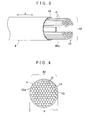
- a conductor wire bundle 42 is structured by tying strands of the conductor wires 41 into a bundle as illustrated in FIG. 3 .
- the insulating cover 43 is an electrically insulating flexible member, and covers the outer circumference 42a of the conductor wire bundle 42.
- the outer circumference 42a of the conductor wire bundle 42 refers to the periphery (outer circumference) of a cross-section of the conductor wire bundle 42, and the cross-section is orthogonal to the extending direction A.
- the outer circumference 42a does not include ends of the conductor wire bundle 42 in the extending direction A. That is, the insulating cover 43 covers the entire outer circumference 42a of the conductor wire bundle 42, and at the same time, covers the entire area of the conductor wire bundle 42 in the extending direction A except for connecting portions formed at the ends in the extending direction A.
- the connecting portions are portions for electrically connecting a covered conductor wire bundle 4 to another covered conductor wire bundle 4 or another conductor. Since the extending direction A of the conductor wire bundle 42 is equal to the extending direction of the covered conductor wire bundle 4, the extending direction of the conductor wire bundle 42 is also indicated by the same symbol "A".
- a flexible material with electrical insulation properties is used as the insulating cover 43.
- various synthetic resins such as fluorocarbon resin, epoxy resin, polyphenylenesulfide may be used.
- “flexible” refers to a property of being bendable or warpable.
- the insulating cover 43 can be formed by, for example, moving the conductor wire bundle 42 along the extending direction A while an appropriate amount of melted resin material is being supplied to the outer circumference 42a of the conductor wire bundle 42.
- the inner circumferential surface of the insulating cover 43 becomes uneven so as to fit the shape of the outer circumference 42a of the conductor wire bundle 42 as illustrated in FIG. 4 .
- no gaps are formed between the insulating cover 43 and the outer circumference 42a of the conductor wire bundle 42, more specifically, between the insulating cover 43 and the surfaces of the outermost conductor wires 41 in the conductor wire bundle 42 in the radial directions.
- the conductor wires 41 used each have a circular cross section orthogonal to the extending direction A as described above.
- gaps G are formed between the plurality of conductor wires 41 that structure the conductor wire bundle 42.
- the insulating cover 43 can also be formed by, for example, wrapping the outer circumference 42a of the conductor wire bundle 42 in a sheet-like material or cylindrical material.
- the gaps G are formed between the plurality of conductor wires 41 that structure the conductor wire bundle 42 and between the inner circumferential surface of the insulating cover 43 and the outer circumference 42a of the conductor wire bundle 42 unlike the example illustrated in FIG. 4 .
- the covered conductor wire bundle 4 according to this embodiment has the gaps G in the space enclosed by the insulating cover 43.
- the covered conductor wire bundle 4 has a structure in which the outer circumference 42a of the conductor wire bundle 42 consisting of an assembly of the plurality of conductor wires 41 is covered by the flexible insulating cover 43 as described above, the plurality of conductor wires 41 can relatively move inside the insulating cover 43. Therefore, the covered conductor wire bundle 4 is structured such that the shape of the cross-section thereof orthogonal to the extending direction A can be deformed relatively freely (see FIG. 5 ).
- each conductor wire 41 has a circular cross-section with a relatively small diameter, and the gaps G are formed inside the space enclosed by the insulating cover 43 in the covered conductor wire bundle 4 as described above.
- a diameter D (see also FIG. 4 ) of the cross-section of the covered conductor wire bundle 4 is set to be larger than the open width W of the radial opening 22b of the slot 22 in a plane orthogonal to the extending direction A of the covered conductor wire bundle 4 when the cross-section orthogonal to the extending direction A is circular.
- a plurality of covered conductor wire bundles 4 are disposed in each slot 22 of the stator core 2 such that adjacent covered conductor wire bundles 4 are in contact with each other.
- six covered conductor wire bundles 4 are disposed in each slot 22.
- the covered conductor wire bundles 4 are disposed in each slot 22 so as to form a line extending in the radial direction R at the same position in the circumferential direction C.
- the stator 1 has a multilayer winding structure (herein a six-layer winding structure) in which the plurality of covered conductor wire bundles 4 are aligned in the radial direction R.
- each of the covered conductor wire bundles 4 is disposed in the corresponding slot 22 so as to extend linearly along the slot 22 in the extending direction A parallel to the axial direction L.
- the number of covered conductor wire bundles 4 disposed in each slot 22 is counted by focusing only on portions located inside the slot 22. Therefore, a structure in which six covered conductor wire bundles 4 are disposed in each slot 22 by winding one covered conductor wire bundle 4, which is one continuous wire bundle when detached from the stator core 2, around the same slot 22 six times is also one of preferred embodiments of the present invention.
- each slot 22 it is also preferable that six covered conductor wire bundles 4 be disposed in each slot 22 by winding two covered conductor wire bundles 4, which are two continuous wire bundles when detached from the stator core 2, around the same slot 22 three times or by winding three covered conductor wire bundles 4, which are three continuous wire bundles when detached from the stator core 2, around the same slot 22 two times.
- six covered conductor wire bundles 4 disposed in each slot 22 be six separate wire bundles when detached from the stator core 2.
- the coils 3 are structured by winding the covered conductor wire bundles 4 around the stator core 2 such that the plurality of (herein six) covered conductor wire bundles 4 are disposed in each of the slots 22 of the stator core 2.
- the covered conductor wire bundles 4 are structured such that the shapes of the cross-sections (hereinafter referred to as "cross-sectional shapes" as appropriate) thereof orthogonal to the extending direction A can be easily deformed.
- This enables the covered conductor wire bundles 4 in each slot 22 to be deformed in accordance with the shape of the slot 22 such that the gaps between the covered conductor wire bundles 4 and those between the covered conductor wire bundles 4 and the inner wall surface 22a of the slot 22 are kept small, and thereby leads to an increase in the space factor of the coil 3.
- adjacent covered conductor wire bundles 4 are in contact with each other in each slot 22. More specifically, as illustrated in FIG.
- each of the covered conductor wire bundles 4 has contact surfaces that follow contact surfaces of the adjacent covered conductor wire bundles 4, and is in surface contact with the adjacent covered conductor wire bundles 4 at the contact surfaces.
- all the covered conductor wire bundles 4 disposed in each slot 22 have portions whose shapes follow the inner wall surface 22a of the slot 22, and are in surface contact with the inner wall surface 22a at the portions. That is, the covered conductor wire bundles 4 each have contact surfaces that are parallel to the inner wall surface 22a and that are in surface contact with the inner wall surface 22a.
- surface contact refers to a state where two surfaces having more than or equal to a predetermined area are in contact with each other.
- the predetermined area is set to, for example, more than or equal to the cross-sectional area (cross-sectional area orthogonal to the extending direction A) of the conductor wires 41.
- the contact surfaces of the covered conductor wire bundles 4 described above are formed by deformation of each covered conductor wire bundle 4 pushed toward the inner wall surface 22a or the other covered conductor wire bundles 4 in each slot 22. That is, in this embodiment, the covered conductor wire bundles 4 are disposed in each slot 22 while maintaining the shapes formed when the covered conductor wire bundles 4 are pushed from a radial opening 22b side of the slot 22 that is open in the direction orthogonal to the extending direction A.
- the terms "while maintaining the shapes formed when the covered conductor wire bundles 4 are pushed" indicate a state where the covered conductor wire bundles 4 are deformed in the slot 22 by any small pushing force acting on the covered conductor wire bundles 4 from the radial opening 22b side compared with a natural state where no external force acts on the covered conductor wire bundles 4. Accordingly, the terms also indicate maintenance of the shapes in a state where the covered conductor wire bundles 4 are pushed with pushing force lower than that acting on the covered conductor wire bundles 4 in the slot 22 in processes of manufacturing the stator 1 as described below. In other words, the terms also indicate a state after the pushing force applied in the processes of manufacturing the stator 1 is removed and some return occurs in the shapes of the covered conductor wire bundles 4.
- each covered conductor wire bundle 4 is set such that the plurality of (herein six) covered conductor wire bundles 4 fill the space inside each slot 22. Therefore, when the plurality of (herein six) covered conductor wire bundles 4 are accommodated in the slot 22, the covered conductor wire bundles 4 are deformed by the contact with each other or contact with the inner wall surface 22a of the slot 22, and the gaps between the covered conductor wire bundles 4 and those between the covered conductor wire bundles 4 and the inner wall surface 22a of the slot 22 become significantly small as illustrated in FIG. 2 .
- the shape combining the cross-sectional shapes of the covered conductor wire bundles 4 corresponds to the cross-sectional shape of the slot 22, the cross-sectional shape being orthogonal to the axial direction L.
- the inner wall surface 22a of each slot 22 has two non-parallel planes facing each other and a plane with an arc-shaped cross-section extending in the axial direction L.
- each covered conductor wire bundle 4 is deformed to conform to the shape of the inner wall surface 22a of the slot 22, and the size of the gaps between the covered conductor wire bundles 4 and the inner wall surface 22a can be easily reduced.
- the deformation of the cross-sectional shape of each covered conductor wire bundle 4 enables the covered conductor wire bundles 4 to adhere to adjacent covered conductor wire bundles 4 or enables the covered conductor wire bundles 4 and the inner wall surface 22a to adhere to each other, resulting in small-sized gaps.
- each of the cross-sectional shapes of the covered conductor wire bundles 4 is deformed in various manners since the individual cross-sectional shapes of the covered conductor wire bundles 4 are deformed to conform to the shape of the inner wall surface 22a or the covered conductor wire bundles 4 whose cross-sectional shapes can be easily deformed push each other. This causes differences in the individual cross-sectional shapes of the covered conductor wire bundles 4 disposed in the same slot 22.
- a closing member 25 for closing the radial opening 22b is disposed at the radial opening 22b of each slot 22 to prevent protrusion of the covered conductor wire bundles 4 from the radial opening 22b.
- the closing member 25 is a tabular member that closes the entire radial opening 22b. Such members are referred to as so-called wedges.
- This closing member 25 supports the covered conductor wire bundles 4 from the inner side in the radial direction R by coming into contact with the surfaces located outward in the radial direction R in the circumferential protruding portions 23b which are formed at the end portion of the teeth 23.
- the closing member 25 has a width larger than the open width W of the radial opening 22b of the slot 22 in the circumferential direction C and a length equal to that of the stator core 2 in the axial direction L.
- This closing member 25 is preferably composed of a material with relatively high magnetic and electrical resistance such as synthetic resins.
- a structure in which no closing member 25 is disposed at the radial opening 22b is also one of preferred embodiments.
- the covered conductor wire bundle 4 closest to the radial opening 22b is deformed so as to be larger than the open width W of the radial opening 22b in the slot 22 in the circumferential direction C to function as the closing member 25. This enables the covered conductor wire bundles 4 to maintain the shapes formed when pushed from the radial opening 22b side of the slot 22.
- the covered conductor wire bundles 4 accommodated in a slot 22 protrude from the ends of the stator core 2 in the axial direction L, and extend in the circumferential direction C to be accommodated in another slot 22.
- the stator core 2 has forty-eight slots 22 distributed in the circumferential direction C, and the number of slots per pole per phase is set to "2".
- the covered conductor wire bundles 4 in the slot 22 are connected to the covered conductor wire bundles 4 in another slot 22 formed at a position remote from the slot 22 by six slots. Although only a part of the covered conductor wire bundles 4 connecting a pair of slots 22 is illustrated in FIG.
- all the slots 22 are similarly connected in pairs by parts of the covered conductor wire bundles 4 protruding from the stator core 2 in the axial direction L and extending in the circumferential direction C in practical cases.
- the coil end portions are formed of the assemblies of the covered conductor wire bundles 4 protruding from the stator core 2.
- the coil end portions refer to portions of the coils 3 protruding from the stator core 2 outward in the axial direction L.
- the specific layout of the covered conductor wire bundles 4 at the coil end portions varies in accordance with the winding methods, including lap winding and wave winding, of the coils 3. In the present invention, the winding methods of the coils 3 may be freely selected as described above.
- FIG. 5 is a view illustrating processes of manufacturing the stator 1 according to this embodiment in sequence.
- FIG. 5 and the description using FIG. 5 below focus on only one slot 22 among the plurality of slots 22 of the stator core 2.
- the stator 1 can be manufactured by performing the same processes on the other slots 22.
- the covered conductor wire bundles 4 are fitted into the slot 22 as illustrated in FIG. 5A .
- the covered conductor wire bundles 4 are fitted from the radial opening 22b one by one. In this manner, the covered conductor wire bundles 4 are fitted into the slot 22 from the inner side toward outer side in the radial direction R through the radial opening 22b.
- the diameter D of the cross-sectional shape of the covered conductor wire bundle 4 is larger than the open width W of the radial opening 22b of the slot 22 in the circumferential direction C when the cross-sectional shape is a circle. Accordingly, the covered conductor wire bundles 4 are fitted from the radial opening 22b into the slot 22 while the cross-sectional shapes of the covered conductor wire bundles 4 are deformed such that the width thereof in the circumferential direction C is smaller than or equal to the open width W.
- the diameter of the covered conductor wire bundles 4 is larger than the open width W of the radial opening 22b as described above, the number of turns of the covered conductor wire bundles 4 around the stator core 2 can be kept small, and thereby the winding process can be performed efficiently.
- the covered conductor wire bundles 4 are pushed from the radial opening 22b of the slot 22 as illustrated in FIG. 5B .
- a pushing jig 5 is fitted from the radial opening 22b such that the covered conductor wire bundles 4 are pushed outward in the radial direction R.
- the covered conductor wire bundles 4 in the slot 22 to be deformed to conform to the shape of the slot 22 such that the gaps between the covered conductor wire bundles 4 and the inner wall surface 22a of the slot 22 and those between the covered conductor wire bundles 4 are made small.
- the closing member 25 is fitted into the radial opening 22b of the slots 22 as illustrated in FIG.
- the closing member 25 is disposed between the circumferential protruding portions 23b of the teeth 23 and the surface of the covered conductor wire bundle 4 closest to the radial opening 22b (the surface located most inward in the radial direction R) among the plurality of covered conductor wire bundles 4 in the slot 22.
- the tabular closing member 25 can be fitted from the axial opening 22c of the slot 22 in the axial direction L.
- the closing member 25 disposed in this manner can prevent the covered conductor wire bundles 4 disposed in the slot 22 from protruding from the radial opening 22b.
- the covered conductor wire bundles 4 can maintain the shapes formed when pushed from the radial opening 22b side of the slot 22.
- each of the covered conductor wire bundles 4 disposed in each slot 22 has a cross-sectional shape that differs from those of the other covered conductor wire bundles 4 in the same slot 22.
- the contact surfaces of adjacent pairs of the covered conductor wire bundles 4 in each slot 22 extend in a direction orthogonal to the radial direction R (circumferential direction C) as illustrated in FIGS. 2 and 5 .
- the contact surfaces of adjacent pairs of the covered conductor wire bundles 4 are mostly not arranged in such an orderly manner, and it is conceivable that the contact surfaces of adjacent pairs of the covered conductor wire bundles 4 in the slot 22 are often disposed randomly facing in various directions as illustrated in, for example, FIG. 6 .
- the cross-sectional shapes of the covered conductor wire bundles 4 disposed in the same slot 22 significantly differ from each other.
- the gaps in the slot 22 can be kept small and thereby the space factor of the coil 3 can be increased also in this structure by placing the covered conductor wire bundles 4 such that the covered conductor wire bundles 4 maintain the shapes formed when the covered conductor wire bundles 4 are pushed from the radial opening 22b side of the slot 22 as in the above-described embodiment. Accordingly, this structure is also one of preferred embodiments of the present invention.
- the teeth 23 are parallel teeth each having the two side surfaces 23a parallel to each other and the width of the slots 22 in the circumferential direction C increases outward in the radial directions R.
- the embodiments of the present invention are not limited to this structure.
- a structure in which the slots 22 are so-called parallel slots whose width in the circumferential direction C is fixed regardless of the position in the radial directions R as illustrated in FIG. 7 is also one of preferred embodiments of the present invention.
- the inner wall surface 22a of each slot 22 has two planes facing each other in the circumferential direction C and being parallel to each other. In the example illustrated in FIG.
- each slot 22 has a plane orthogonal to the radial direction R formed at an outward portion of the inner wall surface 22a in the radial direction R.
- the slot 22 can be formed such that the width of the slot 22 in the circumferential direction C decreases outward in the radial direction R as illustrated in FIG. 8 .
- the inner wall surface 22a of each slot 22 has two planes formed such that the two planes face each other in the circumferential direction C and the gap between the two planes decreases outward in the radial direction R.
- each tooth 23 has the circumferential protruding portions 23b at the end portion thereof and the open width W of the radial opening 22b in each slot 22 is smaller than other portions, that is, the slots 22 are so-called semi-open slots.
- the embodiments of the present invention are not limited to this structure.
- a structure in which no circumferential protruding portions 23b are formed at the end portion of each tooth 23 and the inner wall surface 22a of each slot 22 extends to the radial opening 22b while remaining flat as illustrated in FIG. 9 , that is, the slots 22 are so-called open slots is also one of preferred embodiments of the present invention.
- wedges such as the closing member 25 for closing the radial opening 22b may be provided in this case, a structure which does not include the closing member 25 may be employed as illustrated in FIG. 9 .
- all the plurality of (six) covered conductor wire bundles 4 disposed in each slot 22 are aligned in the radial direction R.
- the embodiments of the present invention are not limited to this structure.
- a structure in which the covered conductor wire bundles 4 aligned in the radial direction R are arranged in a plurality of rows in the circumferential direction C in each slot 22 is also one of preferred embodiments of the present invention.
- twelve covered conductor wire bundles 4 be aligned in the radial direction R in two rows of six such that the two rows are arranged adjacent to each other in the circumferential direction C in each slot 22 as illustrated in FIG. 10 .
- all the covered conductor wire bundles 4 disposed in each slot 22 are in surface contact with the inner wall surface 22a as illustrated in FIGS. 2 and 6 to 10 .
- the embodiments of the present invention are not limited to this structure, and a structure in which only some of the covered conductor wire bundles 4 disposed in each slot 22 has portions whose shapes follow the inner wall surface 22a of the slot 22 and is in surface contact with the inner wall surface 22a at the portions is also one of preferred embodiments of the present invention.
- the covered conductor wire bundles 4 are disposed in the circumferential direction C.
- some of the covered conductor wire bundles 4 is disposed at positions at which they are only in contact with the other covered conductor wire bundles 4 without being in contact with the inner wall surface 22a of the slot 22.
- the covered conductor wire bundles 4 are disposed in each slot 22 such that the covered conductor wire bundles 4 adjacent to each other are in contact with each other.
- the diameter D of the cross-sectional shapes of the covered conductor wire bundles 4 is larger than the open width W of the radial openings 22b of the slots 22 when the cross-sectional shapes are circles.
- the embodiments of the present invention are not limited to this structure. That is, a structure in which the diameter D of the cross-sectional shapes of the covered conductor wire bundles 4 is smaller than the open width W of the radial openings 22b of the slots 22 when the cross-sectional shapes are circles is also one of preferred embodiments of the present invention.
- the slot insulating portions 24 are formed on the inner wall surfaces 22a of the slots 22 by insulating powder coating.
- the structure of the slot insulating portions 24 is not limited to this.
- a structure in which the slot insulating portions 24 are formed of slot insulating sheets placed along the inner wall surfaces 22a of the slots 22 is also one of preferred embodiments of the present invention.
- the slot insulating portions 24 do not need to extend to the radial openings 22b of the slots 22, and are basically formed only in areas where the covered conductor wire bundles 4 are to be disposed.
- FIG. 7 illustrates an example structure of such slot insulating portions 24.
- a structure in which the inner wall surfaces 22a of the slots 22 have no slot insulating portions 24 is also one of preferred embodiments of the present invention. Since the outer circumferential surfaces of the covered conductor wire bundles 4 are covered with the insulating covers 43, the covered conductor wire bundles 4 are electrically insulated from the stator core 2 also in this case.
- the cross-sections of the conductor wires 41 have a circular shape.
- the embodiments of the present invention are not limited to this structure.
- a structure in which cross-sections of the conductor wires 41 that are orthogonal to the extending direction A, have, for example, a polygonal shape such as a rectangular, triangular, pentagonal, hexagonal, and octagonal shape is also one of preferred embodiments of the present invention.
- the slots 22 have the radial openings 22b that are open inward in the radial directions R.
- This structure is suitable for a rotating electrical machine of the inner rotor type including a rotor disposed inward of the stator 1 in the radial directions R.
- the embodiments of the present invention are not limited to this.
- a structure in which the slots 22 have radial openings that are open outward in the radial directions R is also one of preferred embodiments of the present invention.
- This structure is suitable for a rotating electrical machine of the outer rotor type including a rotor disposed outward of the stator 1 in the radial directions R.
- the present invention can be preferably used for rotating electrical machines of the axial gap type in addition to those of the radial gap type.
- the present invention can be preferably used for a stator for a rotating electrical machine including a stator core with a plurality of slots and coils attached to the stator core.
Landscapes
- Engineering & Computer Science (AREA)
- Power Engineering (AREA)
- Manufacturing & Machinery (AREA)
- Windings For Motors And Generators (AREA)
- Insulation, Fastening Of Motor, Generator Windings (AREA)
- Manufacture Of Motors, Generators (AREA)
Abstract
Description
- The present invention relates to a stator for a rotating electrical machine including a stator core with a plurality of slots and coils attached to the stator core.
- Up to now, a rotating electrical machine serving as an electric motor or a power generator has used a stator for a rotating electrical machine including a stator core with a plurality of slots and coils attached to the stator core. For example, Japanese Patent Application Publication No.
09-009588 JP 09-009588 A - In such a stator for a rotating electrical machine including coils structured using conductor wires with circular cross-sections, gaps are easily left between the conductor wires in slots, and therefore it is difficult to increase a space factor of the coils. Although a reduction of the diameter of the conductor wires may be effective in reducing the size of the gaps between the conductor wires to increase the space factor, a reduction of the diameter of the conductor wires may require, for example, devices to prevent breaks in the conductor wires during winding of the conductor wires around the stator core, and a long time in a winding process due to the increased number of turns around the stator core. Meanwhile, structuring coils using conductor wires with rectangular cross-sections may also be effective in increasing the space factor of the coils. However, the shapes of the slots are substantially limited to rectangles, and the shapes of the slots or teeth may not be optimized.
-
- Patent Document 1: Japanese Patent Application Publication No.
09-009588 JP 09-009588 A - To solve this problem, a stator for a rotating electrical machine, capable of simplifying a process of winding wire around a stator core and capable of increasing the space factor of coils regardless of the shape of slots, is desired.
- A stator for a rotating electrical machine according to the present invention, including a stator core with a plurality of slots and coils attached to the stator core, has a characteristic structure in which the coils are each structured by winding a covered conductor wire bundle around the stator core; the covered conductor wire bundle is structured by covering an outer circumference of a conductor wire bundle with a flexible insulating cover, the conductor wire bundle consisting of an assembly of a plurality of conductor wires; and a plurality of the covered conductor wire bundles is disposed in each slot such that adjacent pairs of the covered conductor wire bundles are in contact with each other.
- Herein, the outer circumference of the conductor wire bundle refers to the periphery (outer circumference) of a cross-section of the conductor wire bundle, and the cross-section is orthogonal to a direction along which the conductor wire bundle extends. In the present invention, the number of covered conductor wire bundles disposed in each slot is counted by focusing only on portions located inside the slot. Consequently, the concept of the covered conductor wire bundles disposed in each slot in the present invention includes the covered conductor wire bundles interconnected outside the slot to form one covered conductor wire bundle when detached from the stator core. In the present invention, the term "rotating electrical machine" is used as a concept including a motor (electric motor), a generator (power generator), and a motor/generator that functions as both a motor and a generator as required.
- According to this characteristic structure, the shapes of the cross-sections of the covered conductor wire bundles can be deformed relatively freely, the cross-sections being orthogonal to the extending direction of the covered conductor wire bundles. This would facilitate insertion of the covered conductor wire bundles into the slots if openings of the slots are narrow. In addition, each of the covered conductor wire bundles is structured by tying the plurality of conductor wires. This enables thin conductor wires to be used to increase the space factor and the number of turns of wire around the stator core to be kept small to increase efficiency of the winding process of the covered conductor wire bundles. Furthermore, the conductor wire bundles are covered with the insulating covers. This can reduce the risk of damage to the conductor wires when the conductor wires are fitted into the slots, and can easily increase the insulation properties. In addition, gaps between the covered conductor wire bundles can be kept small by placing the covered conductor wire bundles such that adjacent pairs of the covered conductor wire bundles are in contact with each other after the covered conductor wire bundles are fitted in the slots, and gaps between the covered conductor wire bundles and the inner wall surfaces of the slots can be kept small by deforming the covered conductor wire bundles in accordance with the shapes of the slots. This enables the space factor to be further increased. Accordingly, this characteristic structure provides a stator for a rotating electrical machine capable of simplifying a process of winding wire around a stator core and capable of increasing the space factor of coils regardless of the shape of slots.
- Herein, it is preferred that the cross-sections of the covered conductor wire bundles disposed in the same slots have different shapes, the cross-sections being orthogonal to the extending direction of the covered conductor wire bundles.
- Since the shapes of the cross-sections of the covered conductor wire bundles disposed in each slot are deformed so as to differ from each other as described above, the gaps between the covered conductor wire bundles and those between the covered conductor wire bundles and the inner wall surface of the slot can be easily kept small in accordance with the shape of the slot. This can lead to an increase in the space factor of the coils regardless of the shapes of the slots.
- In addition, it is preferred that at least one of the covered conductor wire bundles disposed in each slot have a portion whose shape follows the inner wall surface of the slot, and be in surface contact with the inner wall surface at the portion.
- Since at least one of the covered conductor wire bundles disposed in each slot is deformed in accordance with the shape of the slot and is in surface contact with the inner wall surface of the slot such that the size of the gaps between the covered conductor wire bundle and the inner wall surface is reduced, the space factor of the coils can be increased regardless of the shapes of the slots.
- In addition, it is preferred that the conductor wires each have a circular cross-section orthogonal to a direction along which the conductor wires extend.
- According to this structure, the covered conductor wire bundles each have gaps formed in a space enclosed by the insulating cover. This enables the conductor wires in the space enclosed by the insulating cover to move easily, and thereby enables the cross-sectional shapes of the covered conductor wire bundles to be deformed more easily. As a result, the covered conductor wire bundles can be easily fitted into the slots. In addition, the covered conductor wire bundles can be deformed such that the gaps between the covered conductor wire bundles and those between the covered conductor wire bundles and the inner wall surfaces of the slots are kept small after the covered conductor wire bundles are fitted in the slots. This enables the space factor of the coils to be easily increased.
- In addition, it is preferred that the diameter of the cross-sections of the covered conductor wire bundles be larger than the open width of openings of the slots in a plane orthogonal to the direction along which the covered conductor wire bundles extend when the cross-sections orthogonal to the extending direction are circular.
- This structure enables the number of turns of wire around the stator core to be kept small, thereby easily leading to greater efficiency of the winding process. The shapes of the cross-sections of the covered conductor wire bundles can be deformed relatively freely also in this case, and the covered conductor wire bundles can be easily fitted into the slots.
- In addition, it is preferred that the covered conductor wire bundles be disposed in each slot while maintaining the shapes formed when the covered conductor wire bundles are pushed from an opening side of the slot that is open in a direction orthogonal to the extending direction of the covered conductor wire bundles.
- This structure enables a state where the covered conductor wire bundles push each other in the slots. As a result, the covered conductor wire bundles can be disposed in the slots while deformed in accordance with the shapes of the slots such that the size of the gaps between the covered conductor wire bundles and those between the covered conductor wire bundles and the inner wall surfaces of the slots is reduced. This can lead to an increase in the space factor of the coils regardless of the shapes of the slots.
- In addition, it is preferred that the conductor wires be bare wires. Herein, bare wires refer to open conductor wires that do not have surfaces covered with insulator. Accordingly, conductor wires having surfaces on which covers or films, composed of electrically insulating material such as resin, are formed are not included in the bare wires. However, conductor wires having surfaces on which oxide films are formed are included in the bare wires.
- With this structure, the cross-sectional area of the conductor in the cross-sections of the covered conductor wire bundles can be easily increased compared with the case where insulating covers or films are formed on the surfaces of the conductor wires. As a result, the density of the conductor in the slots can be increased, and thereby the space factor of the coils can be easily increased.
- In addition, it is preferred that the slots extend in an axial direction of a cylindrical core reference plane of the stator core and be distributed in a circumferential direction of the core reference plane, that the stator core have a plurality of teeth formed between two adjacent slots, and that each tooth have two side surfaces that face in the circumferential direction and that are parallel to each other.
- With this structure, the cross-sectional area of a magnetic path in each tooth can be uniform in all the teeth. As a result, unnecessary teeth width can be reduced to maximize the space inside the slots while a required amount of magnetic flux is ensured in each tooth, and the proportion of the cross-sectional area of the coils to that of the stator can be easily increased.
-
- [
FIG. 1] FIG. 1 is a perspective view of a stator for a rotating electrical machine according to an embodiment of the present invention. - [
FIG. 2] FIG. 2 is a partially enlarged cross-sectional view of the stator for the rotating electrical machine according to the embodiment of the present invention. - [
FIG. 3] FIG. 3 is a perspective view illustrating the structure of a covered conductor wire bundle of the stator for the rotating electrical machine according to the embodiment of the present invention. - [
FIG. 4] FIG. 4 is a cross-sectional view illustrating the structure of the covered conductor wire bundle of the stator for the rotating electrical machine according to the embodiment of the present invention. - [
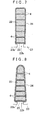
FIG. 5] FIG. 5 is a view illustrating processes of manufacturing the stator for the rotating electrical machine according to the embodiment of the present invention. - [
FIG. 6] FIG. 6 is a partially enlarged cross-sectional view illustrating another embodiment of the stator for the rotating electrical machine according to the present invention. - [
FIG. 7] FIG. 7 is a partially enlarged cross-sectional view illustrating another embodiment of the stator for the rotating electrical machine according to the present invention. - [
FIG. 8] FIG. 8 is a partially enlarged cross-sectional view illustrating another embodiment of the stator for the rotating electrical machine according to the present invention. - [
FIG. 9] FIG. 9 is a partially enlarged cross-sectional view illustrating another embodiment of the stator for the rotating electrical machine according to the present invention. - [
FIG. 10] FIG. 10 is a partially enlarged cross-sectional view illustrating another embodiment of the stator for the rotating electrical machine according to the present invention. - A stator for a rotating electrical machine according to an embodiment of the present invention will now be described with reference to the drawings. Herein, an example of the stator for the rotating electrical machine according to the present invention applied to a stator 1 of a rotating electrical machine of the inner rotor type will be described. The stator 1 according to this embodiment includes a
stator core 2 andcoils 3 attached to thestator core 2 as illustrated inFIG. 1 . Thecoils 3 are structured by winding covered conductor wire bundles 4 around thestator core 2. As illustrated inFIG. 3 , the covered conductor wire bundles 4 each have a structure in which anouter circumference 42a of aconductor wire bundle 42 consisting of an assembly of a plurality ofconductor wires 41 is covered with a flexible insulatingcover 43. The stator 1 according to this embodiment is characterized in that the stator 1 uses such covered conductor wire bundles 4. The structure of the stator 1 according to this embodiment will now be described in detail. In the description below, the terms "axial direction L", "circumferential direction C", and "radial directions R" are defined with respect to the center axis of a cylindricalcore reference plane 21 of the stator core 2 (for example, the inner circumferential surface of the stator core 2) described below unless otherwise specified. - The entire structure of the stator 1 according to this embodiment will now be described with reference to
FIGS. 1 and2 . As illustrated inFIG. 1 , the stator 1 includes thestator core 2 and thecoils 3. Herein, coil end portions refer to portions of thecoils 3 protruding from thestator core 2 in the axial direction L, andFIG. 1 illustrates only a coil end portion protruding from a pair ofslots 22 for purposes of brevity. Accordingly,FIG. 1 illustrates cross-sections of the covered conductor wire bundles 4 that structure thecoils 3 at end portions of theother slots 22 in the axial direction L. - The
stator core 2 is composed of a magnetic material, and has the plurality ofslots 22 such that thecoils 3 can be wound. Herein, theslots 22 extend in the axial direction L of the cylindricalcore reference plane 21 of thestator core 2, and are distributed in the circumferential direction C of thecore reference plane 21. In addition, theslots 22 are formed so as to radially extend from the center axis of thestator core 2 in the radial directions R. Herein, the term "cylindricalcore reference plane 21" refers to a virtual plane serving as a reference in terms of the layout and the structure of theslots 22. In this embodiment, the inner circumferential surface of the core serving as a virtual cylindrical plane including end surfaces of a plurality ofteeth 23 located inward in the radial directions R, eachtooth 23 being formed between twoadjacent slots 22, is defined as thecore reference plane 21 as illustrated inFIG. 1 . Herein, a cylindrical plane (including a virtual plane) coaxial with the cylindrical inner circumferential surface of the core and having a cross-sectional shape similar to that of the inner circumferential surface of the core when viewed in the axial direction L may also be the "cylindricalcore reference plane 21" according to the present invention. In this embodiment, for example, the outer circumferential surface of thestator core 2 may also be defined as the "cylindricalcore reference plane 21" since thestator core 2 has a cylindrical shape as illustrated inFIG. 1 . - The
stator core 2 has the plurality ofslots 22 distributed in the circumferential direction C at regular intervals. Theslots 22 have the same shape. Thestator core 2 further has theplurality ofteeth 23 each formed between twoadjacent slots 22. In this embodiment, theslots 22 have a groove-like shape having a predetermined width in the circumferential direction C and extending in the axial direction L and in the radial directions R. In this embodiment, twoside surfaces 23a of eachtooth 23 facing in the circumferential direction C are parallel to each other, that is, theteeth 23 are parallel teeth as illustrated inFIG. 2 . As a result, the width of eachslot 22 in the circumferential direction C increases outward in the radial direction R. That is, aninner wall surface 22a of eachslot 22 includes two planes facing each other in the circumferential direction C and formed such that the gap between the two planes increases outward in the radial direction R, and a plane with an arc-shaped cross-section formed outward of the two planes in the radial direction R and extending in the axial direction L. In addition, eachslot 22 is formed to have anradial opening 22b that is open inward in the radial direction R (open in the inner circumferential surface of the stator core 2) andaxial openings 22c that are open in both sides of thestator core 2 in the axial direction L (both end surfaces in the axial direction). Aslot insulating portion 24 is formed on theinner wall surface 22a of eachslot 22. In this embodiment, the entire inner wall surfaces 22a are coated with insulating powder, and theslot insulating portions 24 are formed of the coating films of the insulating powder coating. - Each
tooth 23 is formed between twoslots 22 adjacent to each other in the circumferential direction C of thestator core 2. In this embodiment, eachtooth 23 is formed such that twoparallel side surfaces 23a (hereinafter simply referred to as "tooth side surfaces 23a") faces each other in the circumferential direction C of thetooth 23. That is, thestator core 2 according to this embodiment includes parallel teeth. Herein, circumferential protrudingportions 23b are formed at an end portion of eachtooth 23 so as to protrude in the circumferential direction C with respect to other portions of thetooth side surfaces 23a. As a result, most of the two tooth side surfaces 23a are parallel to each other except for the stepped portions for forming the circumferential protrudingportions 23b. As is clear fromFIG. 2 , these two tooth side surfaces 23a are disposed to be parallel to each other in the radial directions R. - Since each
tooth 23 has the circumferential protrudingportions 23b at the end portion thereof as described above, the open width W of theradial opening 22b of eachslot 22 is reduced compared with the width of other portions located outward in the radial direction R. Herein, the open width W of theradial opening 22b refers to the width of theradial opening 22b in the circumferential direction C, that is, the width in a direction orthogonal to the radial direction R. As illustrated in the cross-section inFIG. 2 , the open width W is the width of theradial opening 22b in a plane orthogonal to the axial direction L of the stator 1. In addition, the open width W of theradial opening 22b of eachslot 22 is reduced compared with the width of the portion, at which thecoil 3 is disposed, in the circumferential direction C. In general, theseslots 22 are referred to as semi-open slots. In this embodiment, theradial openings 22b function as openings of theslots 22 which open in a direction orthogonal to an extending direction A of the covered conductor wire bundles 4, since the extending direction A of the covered conductor wire bundles 4 is parallel to the axial direction L as described below. In addition, the open width W of theradial openings 22b in the circumferential direction C corresponds to the open width of the openings of theslots 22 in a plane orthogonal to the extending direction A of the covered conductor wire bundles 4. - The rotating electrical machine in this embodiment is a three-phase AC motor or a three-phase AC generator driven by three-phase alternating currents (U-phase, V-phase, and W-phase). Accordingly, the
coils 3 of the stator 1 are respectively classified as U-phase coils, V-phase coils, and W-phase coils according to the three phases (U-phase, V-phase, and W-phase, respectively), and theslots 22 for U-phase, V-phase, and W-phase are laid out so as to repeatedly appear in the circumferential direction C in thestator core 2. In this example, two U-phase slots into which the U-phase coils are fitted, two V-phase slots into which the V-phase coils are fitted, and two W-phase slots into which the W-phase coils are fitted are laid out in thestator core 2 so as to repeatedly appear in the circumferential direction C in this order such that the number of slots per pole per phase becomes "2". Thecoils 3 are structured by winding the covered conductor wire bundles 4 around thestator core 2. The covered conductor wire bundles 4 may be wound around thestator core 2 using various well-known methods. For example, thecoils 3 may be structured by winding the covered conductor wire bundles 4 around thestator core 2 using a combination of one of lap winding and wave winding and one of concentrated winding and distribution winding. - In this manner, the stator 1 is structured as an armature of the rotating electrical machine. Although not illustrated, a rotor serving as a field magnet including permanent magnets or electromagnets is disposed inward in the radial directions R of the stator 1 (stator core 2) so as to be relatively rotatable with respect to the stator 1. The rotor rotates in response to a revolving field generated by the stator 1. That is, the stator 1 according to this embodiment has a structure used for a rotating electrical machine of the inner rotor type and of the revolving-field type.
- The above-described
stator core 2 may be, for example, a layered structure including a laminate of a plurality of annular disc-shaped magnetic steel sheets, or may be mainly formed of a compact formed by pressure-forming magnetic powder. Although theslots 22 are formed in thestator core 2 such that the number of slots per pole per phase is "2" in this embodiment, the number of slots per pole per phase may be changed as appropriate as a matter of course. For example, the number of slots per pole per phase may be set to "1", "3", or the like. The number of phases of the AC power source that drives the rotating electrical machine may also be changed to, for example, "1", "2", or "4" as appropriate. - Next, the covered conductor wire bundles 4 that structure the
coils 3 will be described. The covered conductor wire bundles 4 are conductors that structure thecoils 3 of each phase, and thecoils 3 of the stator 1 are structured by winding the covered conductor wire bundles 4 around thestator core 2. As illustrated inFIG. 3 , the covered conductor wire bundles 4 each include theconductor wire bundle 42 consisting of an assembly of theconductor wires 41 and the flexible insulatingcover 43 that covers theouter circumference 42a of theconductor wire bundle 42. - The
conductor wires 41 are linear conductors composed of, for example, copper or aluminum. In this embodiment, eachconductor wire 41 has a circular cross section orthogonal to a direction along which theconductor wire 41 extends, and the diameter thereof is relatively small. For example, theconductor wires 41 having a circular cross-section with a diameter of 0.2 mm or less are preferably used. In addition, theconductor wires 41 used in this embodiment are bare wires. That is, the surfaces of theconductor wires 41 formed of the bare wires composed of, for example, copper or aluminum are not covered with insulator, and the surfaces of the conductors are exposed. Although oxide films formed by oxidation of the surfaces of the conductors may have low electrical insulation properties in some cases, these oxide films are not included in the insulator described herein. Accordingly, the conductors having oxide films formed on the surfaces thereof are also included in theconductor wires 41 formed of the bare wires. Preferably, insulating films composed of an electrically insulating material such as resin (for example, polyamide-imide resin and polyimide resin) may also be formed on the surfaces of theconductor wires 41. These insulating films are formed as films that cover the respective surfaces of theconductor wires 41 unlike the insulatingcover 43 described below. - The plurality of
conductor wires 41 is assembled to structure aconductor wire bundle 42. The number ofconductor wires 41 that structure theconductor wire bundle 42 is determined in accordance with the final thickness (cross-sectional area) of the coveredconductor wire bundle 4 and the thickness (cross-sectional area) and the shape of eachconductor wire 41. In this embodiment, the thickness (cross-sectional area) of each coveredconductor wire bundle 4 is set such that six covered conductor wire bundles 4 fill the space inside eachslot 22 as illustrated inFIG. 2 , and the thickness (cross-sectional area) of the conductor wire bundles 42 and the thickness (cross-sectional area), the number, and the like of theconductor wires 41 are set accordingly. In this embodiment, aconductor wire bundle 42 is structured by tying strands of theconductor wires 41 into a bundle as illustrated inFIG. 3 . - The insulating
cover 43 is an electrically insulating flexible member, and covers theouter circumference 42a of theconductor wire bundle 42. Herein, theouter circumference 42a of theconductor wire bundle 42 refers to the periphery (outer circumference) of a cross-section of theconductor wire bundle 42, and the cross-section is orthogonal to the extending direction A. Theouter circumference 42a does not include ends of theconductor wire bundle 42 in the extending direction A. That is, the insulatingcover 43 covers the entireouter circumference 42a of theconductor wire bundle 42, and at the same time, covers the entire area of theconductor wire bundle 42 in the extending direction A except for connecting portions formed at the ends in the extending direction A. Herein, the connecting portions are portions for electrically connecting a coveredconductor wire bundle 4 to another coveredconductor wire bundle 4 or another conductor. Since the extending direction A of theconductor wire bundle 42 is equal to the extending direction of the coveredconductor wire bundle 4, the extending direction of theconductor wire bundle 42 is also indicated by the same symbol "A". A flexible material with electrical insulation properties is used as the insulatingcover 43. For example, various synthetic resins such as fluorocarbon resin, epoxy resin, polyphenylenesulfide may be used. Herein, "flexible" refers to a property of being bendable or warpable. - The insulating
cover 43 can be formed by, for example, moving theconductor wire bundle 42 along the extending direction A while an appropriate amount of melted resin material is being supplied to theouter circumference 42a of theconductor wire bundle 42. In a case where the insulatingcover 43 is formed using the melted resin material in this manner, the inner circumferential surface of the insulatingcover 43 becomes uneven so as to fit the shape of theouter circumference 42a of theconductor wire bundle 42 as illustrated inFIG. 4 . In this case, no gaps are formed between the insulatingcover 43 and theouter circumference 42a of theconductor wire bundle 42, more specifically, between the insulatingcover 43 and the surfaces of theoutermost conductor wires 41 in theconductor wire bundle 42 in the radial directions. In this embodiment, however, theconductor wires 41 used each have a circular cross section orthogonal to the extending direction A as described above. As a result, gaps G are formed between the plurality ofconductor wires 41 that structure theconductor wire bundle 42. The insulatingcover 43 can also be formed by, for example, wrapping theouter circumference 42a of theconductor wire bundle 42 in a sheet-like material or cylindrical material. In this case, the gaps G are formed between the plurality ofconductor wires 41 that structure theconductor wire bundle 42 and between the inner circumferential surface of the insulatingcover 43 and theouter circumference 42a of theconductor wire bundle 42 unlike the example illustrated inFIG. 4 . In either case, the coveredconductor wire bundle 4 according to this embodiment has the gaps G in the space enclosed by the insulatingcover 43. - Since the covered
conductor wire bundle 4 has a structure in which theouter circumference 42a of theconductor wire bundle 42 consisting of an assembly of the plurality ofconductor wires 41 is covered by the flexible insulatingcover 43 as described above, the plurality ofconductor wires 41 can relatively move inside the insulatingcover 43. Therefore, the coveredconductor wire bundle 4 is structured such that the shape of the cross-section thereof orthogonal to the extending direction A can be deformed relatively freely (seeFIG. 5 ). In accordance with the structure according to this embodiment, eachconductor wire 41 has a circular cross-section with a relatively small diameter, and the gaps G are formed inside the space enclosed by the insulatingcover 43 in the coveredconductor wire bundle 4 as described above. This enables the cross-sectional shape of the coveredconductor wire bundle 4 to be deformed more easily. As a result, the coveredconductor wire bundle 4 can be easily warped and deformed along the extending direction A (longitudinal direction), and at the same time, the cross-sectional shape thereof orthogonal to the extending direction A can be easily deformed. In this embodiment, as illustrated inFIG. 5A , a diameter D (see alsoFIG. 4 ) of the cross-section of the coveredconductor wire bundle 4 is set to be larger than the open width W of theradial opening 22b of theslot 22 in a plane orthogonal to the extending direction A of the coveredconductor wire bundle 4 when the cross-section orthogonal to the extending direction A is circular. - Next, the layout of the covered conductor wire bundles 4 with respect to the
stator core 2 according to this embodiment will be described in detail. As illustrated inFIG. 2 , a plurality of covered conductor wire bundles 4 are disposed in eachslot 22 of thestator core 2 such that adjacent covered conductor wire bundles 4 are in contact with each other. In the example illustrated inFIG. 2 , six covered conductor wire bundles 4 are disposed in eachslot 22. In this embodiment, the covered conductor wire bundles 4 are disposed in eachslot 22 so as to form a line extending in the radial direction R at the same position in the circumferential direction C. Herein, all the plurality of (herein six) covered conductor wire bundles 4 are disposed in eachslot 22 so as to be aligned in the radial direction R. Accordingly, the stator 1 has a multilayer winding structure (herein a six-layer winding structure) in which the plurality of covered conductor wire bundles 4 are aligned in the radial direction R. In addition, each of the covered conductor wire bundles 4 is disposed in thecorresponding slot 22 so as to extend linearly along theslot 22 in the extending direction A parallel to the axial direction L. - In the present invention, the number of covered conductor wire bundles 4 disposed in each
slot 22 is counted by focusing only on portions located inside theslot 22. Therefore, a structure in which six covered conductor wire bundles 4 are disposed in eachslot 22 by winding one coveredconductor wire bundle 4, which is one continuous wire bundle when detached from thestator core 2, around thesame slot 22 six times is also one of preferred embodiments of the present invention. Similarly, it is also preferable that six covered conductor wire bundles 4 be disposed in eachslot 22 by winding two covered conductor wire bundles 4, which are two continuous wire bundles when detached from thestator core 2, around thesame slot 22 three times or by winding three covered conductor wire bundles 4, which are three continuous wire bundles when detached from thestator core 2, around thesame slot 22 two times. In addition, it is also preferable that six covered conductor wire bundles 4 disposed in eachslot 22 be six separate wire bundles when detached from thestator core 2. In any cases, thecoils 3 are structured by winding the covered conductor wire bundles 4 around thestator core 2 such that the plurality of (herein six) covered conductor wire bundles 4 are disposed in each of theslots 22 of thestator core 2. - As described above, the covered conductor wire bundles 4 are structured such that the shapes of the cross-sections (hereinafter referred to as "cross-sectional shapes" as appropriate) thereof orthogonal to the extending direction A can be easily deformed. This enables the covered conductor wire bundles 4 in each
slot 22 to be deformed in accordance with the shape of theslot 22 such that the gaps between the covered conductor wire bundles 4 and those between the covered conductor wire bundles 4 and theinner wall surface 22a of theslot 22 are kept small, and thereby leads to an increase in the space factor of thecoil 3. In order to reduce the size of the gaps, adjacent covered conductor wire bundles 4 are in contact with each other in eachslot 22. More specifically, as illustrated inFIG. 2 , each of the covered conductor wire bundles 4 has contact surfaces that follow contact surfaces of the adjacent covered conductor wire bundles 4, and is in surface contact with the adjacent covered conductor wire bundles 4 at the contact surfaces. In addition, in this embodiment, all the covered conductor wire bundles 4 disposed in eachslot 22 have portions whose shapes follow theinner wall surface 22a of theslot 22, and are in surface contact with theinner wall surface 22a at the portions. That is, the covered conductor wire bundles 4 each have contact surfaces that are parallel to theinner wall surface 22a and that are in surface contact with theinner wall surface 22a. In this embodiment, surface contact refers to a state where two surfaces having more than or equal to a predetermined area are in contact with each other. The predetermined area is set to, for example, more than or equal to the cross-sectional area (cross-sectional area orthogonal to the extending direction A) of theconductor wires 41. - The contact surfaces of the covered conductor wire bundles 4 described above are formed by deformation of each covered
conductor wire bundle 4 pushed toward theinner wall surface 22a or the other covered conductor wire bundles 4 in eachslot 22. That is, in this embodiment, the covered conductor wire bundles 4 are disposed in eachslot 22 while maintaining the shapes formed when the covered conductor wire bundles 4 are pushed from aradial opening 22b side of theslot 22 that is open in the direction orthogonal to the extending direction A. Herein, the terms "while maintaining the shapes formed when the covered conductor wire bundles 4 are pushed" indicate a state where the covered conductor wire bundles 4 are deformed in theslot 22 by any small pushing force acting on the covered conductor wire bundles 4 from theradial opening 22b side compared with a natural state where no external force acts on the covered conductor wire bundles 4. Accordingly, the terms also indicate maintenance of the shapes in a state where the covered conductor wire bundles 4 are pushed with pushing force lower than that acting on the covered conductor wire bundles 4 in theslot 22 in processes of manufacturing the stator 1 as described below. In other words, the terms also indicate a state after the pushing force applied in the processes of manufacturing the stator 1 is removed and some return occurs in the shapes of the covered conductor wire bundles 4. - In addition, the thickness (cross-sectional area orthogonal to the extending direction A) of each covered
conductor wire bundle 4 is set such that the plurality of (herein six) covered conductor wire bundles 4 fill the space inside eachslot 22. Therefore, when the plurality of (herein six) covered conductor wire bundles 4 are accommodated in theslot 22, the covered conductor wire bundles 4 are deformed by the contact with each other or contact with theinner wall surface 22a of theslot 22, and the gaps between the covered conductor wire bundles 4 and those between the covered conductor wire bundles 4 and theinner wall surface 22a of theslot 22 become significantly small as illustrated inFIG. 2 . In this state, the shape combining the cross-sectional shapes of the covered conductor wire bundles 4 corresponds to the cross-sectional shape of theslot 22, the cross-sectional shape being orthogonal to the axial direction L. In this embodiment, theinner wall surface 22a of eachslot 22 has two non-parallel planes facing each other and a plane with an arc-shaped cross-section extending in the axial direction L. When relatively thick linear conductors with a fixed cross-sectional shape are disposed in thisslot 22, large gaps are easily formed between the linear conductors and theinner wall surface 22a of theslot 22. In accordance with the structure according to this embodiment, however, the cross-sectional shape of each coveredconductor wire bundle 4 is deformed to conform to the shape of theinner wall surface 22a of theslot 22, and the size of the gaps between the covered conductor wire bundles 4 and theinner wall surface 22a can be easily reduced. In this manner, the deformation of the cross-sectional shape of each coveredconductor wire bundle 4 enables the covered conductor wire bundles 4 to adhere to adjacent covered conductor wire bundles 4 or enables the covered conductor wire bundles 4 and theinner wall surface 22a to adhere to each other, resulting in small-sized gaps. At this moment, each of the cross-sectional shapes of the covered conductor wire bundles 4 is deformed in various manners since the individual cross-sectional shapes of the covered conductor wire bundles 4 are deformed to conform to the shape of theinner wall surface 22a or the covered conductor wire bundles 4 whose cross-sectional shapes can be easily deformed push each other. This causes differences in the individual cross-sectional shapes of the covered conductor wire bundles 4 disposed in thesame slot 22. - In order to accommodate the covered conductor wire bundles 4 in each
slot 22 while the gaps are small as described above, it is preferred that the covered conductor wire bundles 4 maintain the shapes formed when the covered conductor wire bundles 4 are pushed from theradial opening 22b side of theslot 22 in eachslot 22. In this embodiment, a closingmember 25 for closing theradial opening 22b is disposed at theradial opening 22b of eachslot 22 to prevent protrusion of the covered conductor wire bundles 4 from theradial opening 22b. Herein, the closingmember 25 is a tabular member that closes the entireradial opening 22b. Such members are referred to as so-called wedges. This closingmember 25 supports the covered conductor wire bundles 4 from the inner side in the radial direction R by coming into contact with the surfaces located outward in the radial direction R in the circumferential protrudingportions 23b which are formed at the end portion of theteeth 23. For this purpose, the closingmember 25 has a width larger than the open width W of theradial opening 22b of theslot 22 in the circumferential direction C and a length equal to that of thestator core 2 in the axial direction L. This closingmember 25 is preferably composed of a material with relatively high magnetic and electrical resistance such as synthetic resins. Herein, a structure in which no closingmember 25 is disposed at theradial opening 22b is also one of preferred embodiments. In this case, the coveredconductor wire bundle 4 closest to theradial opening 22b is deformed so as to be larger than the open width W of theradial opening 22b in theslot 22 in the circumferential direction C to function as the closingmember 25. This enables the covered conductor wire bundles 4 to maintain the shapes formed when pushed from theradial opening 22b side of theslot 22. - As illustrated in
FIG. 1 , the covered conductor wire bundles 4 accommodated in aslot 22 protrude from the ends of thestator core 2 in the axial direction L, and extend in the circumferential direction C to be accommodated in anotherslot 22. In the example illustrated inFIG. 1 , thestator core 2 has forty-eightslots 22 distributed in the circumferential direction C, and the number of slots per pole per phase is set to "2". In addition, the covered conductor wire bundles 4 in theslot 22 are connected to the covered conductor wire bundles 4 in anotherslot 22 formed at a position remote from theslot 22 by six slots. Although only a part of the covered conductor wire bundles 4 connecting a pair ofslots 22 is illustrated inFIG. 1 , all theslots 22 are similarly connected in pairs by parts of the covered conductor wire bundles 4 protruding from thestator core 2 in the axial direction L and extending in the circumferential direction C in practical cases. In this manner, the coil end portions are formed of the assemblies of the covered conductor wire bundles 4 protruding from thestator core 2. Herein, the coil end portions refer to portions of thecoils 3 protruding from thestator core 2 outward in the axial direction L. The specific layout of the covered conductor wire bundles 4 at the coil end portions varies in accordance with the winding methods, including lap winding and wave winding, of thecoils 3. In the present invention, the winding methods of thecoils 3 may be freely selected as described above. - Next, a method of manufacturing the stator 1 according to this embodiment will be described.
FIG. 5 is a view illustrating processes of manufacturing the stator 1 according to this embodiment in sequence.FIG. 5 and the description usingFIG. 5 below focus on only oneslot 22 among the plurality ofslots 22 of thestator core 2. The stator 1 can be manufactured by performing the same processes on theother slots 22. First, the covered conductor wire bundles 4 are fitted into theslot 22 as illustrated inFIG. 5A . Herein, the covered conductor wire bundles 4 are fitted from theradial opening 22b one by one. In this manner, the covered conductor wire bundles 4 are fitted into theslot 22 from the inner side toward outer side in the radial direction R through theradial opening 22b. In this embodiment, the diameter D of the cross-sectional shape of the coveredconductor wire bundle 4 is larger than the open width W of theradial opening 22b of theslot 22 in the circumferential direction C when the cross-sectional shape is a circle. Accordingly, the covered conductor wire bundles 4 are fitted from theradial opening 22b into theslot 22 while the cross-sectional shapes of the covered conductor wire bundles 4 are deformed such that the width thereof in the circumferential direction C is smaller than or equal to the open width W. Since the diameter of the covered conductor wire bundles 4 is larger than the open width W of theradial opening 22b as described above, the number of turns of the covered conductor wire bundles 4 around thestator core 2 can be kept small, and thereby the winding process can be performed efficiently. - After all the (herein six) covered conductor wire bundles 4 are fitted in the
slot 22, the covered conductor wire bundles 4 are pushed from theradial opening 22b of theslot 22 as illustrated inFIG. 5B . Herein, a pushingjig 5 is fitted from theradial opening 22b such that the covered conductor wire bundles 4 are pushed outward in the radial direction R. This enables the covered conductor wire bundles 4 in theslot 22 to be deformed to conform to the shape of theslot 22 such that the gaps between the covered conductor wire bundles 4 and theinner wall surface 22a of theslot 22 and those between the covered conductor wire bundles 4 are made small. Finally, the closingmember 25 is fitted into theradial opening 22b of theslots 22 as illustrated inFIG. 5C . Herein, the closingmember 25 is disposed between the circumferential protrudingportions 23b of theteeth 23 and the surface of the coveredconductor wire bundle 4 closest to theradial opening 22b (the surface located most inward in the radial direction R) among the plurality of covered conductor wire bundles 4 in theslot 22. For example, thetabular closing member 25 can be fitted from theaxial opening 22c of theslot 22 in the axial direction L. The closingmember 25 disposed in this manner can prevent the covered conductor wire bundles 4 disposed in theslot 22 from protruding from theradial opening 22b. In addition, the covered conductor wire bundles 4 can maintain the shapes formed when pushed from theradial opening 22b side of theslot 22. It is also preferable that the closingmember 25 be omitted as described above. Thus, each of the covered conductor wire bundles 4 disposed in eachslot 22 has a cross-sectional shape that differs from those of the other covered conductor wire bundles 4 in thesame slot 22. - Lastly, other embodiments of the present invention will be described. The structure of each embodiment described below is not limited to application in isolation, and may be applied by being combined with the structures of the other embodiments unless otherwise inconsistent.
- (1) In the embodiment described above, the contact surfaces of adjacent pairs of the covered conductor wire bundles 4 in each
slot 22 extend in a direction orthogonal to the radial direction R (circumferential direction C) as illustrated inFIGS. 2 and5 . In practical cases, however, the contact surfaces of adjacent pairs of the covered conductor wire bundles 4 are mostly not arranged in such an orderly manner, and it is conceivable that the contact surfaces of adjacent pairs of the covered conductor wire bundles 4 in theslot 22 are often disposed randomly facing in various directions as illustrated in, for example,FIG. 6 . In this case, the cross-sectional shapes of the covered conductor wire bundles 4 disposed in thesame slot 22 significantly differ from each other. However, the gaps in theslot 22 can be kept small and thereby the space factor of thecoil 3 can be increased also in this structure by placing the covered conductor wire bundles 4 such that the covered conductor wire bundles 4 maintain the shapes formed when the covered conductor wire bundles 4 are pushed from theradial opening 22b side of theslot 22 as in the above-described embodiment. Accordingly, this structure is also one of preferred embodiments of the present invention. - (2) In the embodiment described above, the
teeth 23 are parallel teeth each having the twoside surfaces 23a parallel to each other and the width of theslots 22 in the circumferential direction C increases outward in the radial directions R. However, the embodiments of the present invention are not limited to this structure. For example, a structure in which theslots 22 are so-called parallel slots whose width in the circumferential direction C is fixed regardless of the position in the radial directions R as illustrated inFIG. 7 is also one of preferred embodiments of the present invention. In this case, theinner wall surface 22a of eachslot 22 has two planes facing each other in the circumferential direction C and being parallel to each other. In the example illustrated inFIG. 7 , eachslot 22 has a plane orthogonal to the radial direction R formed at an outward portion of theinner wall surface 22a in the radial direction R. In addition, theslot 22 can be formed such that the width of theslot 22 in the circumferential direction C decreases outward in the radial direction R as illustrated inFIG. 8 . In this case, theinner wall surface 22a of eachslot 22 has two planes formed such that the two planes face each other in the circumferential direction C and the gap between the two planes decreases outward in the radial direction R. - (3) In the embodiment described above, each
tooth 23 has the circumferential protrudingportions 23b at the end portion thereof and the open width W of theradial opening 22b in eachslot 22 is smaller than other portions, that is, theslots 22 are so-called semi-open slots. However, the embodiments of the present invention are not limited to this structure. For example, a structure in which nocircumferential protruding portions 23b are formed at the end portion of eachtooth 23 and theinner wall surface 22a of eachslot 22 extends to theradial opening 22b while remaining flat as illustrated inFIG. 9 , that is, theslots 22 are so-called open slots, is also one of preferred embodiments of the present invention. Although wedges such as the closingmember 25 for closing theradial opening 22b may be provided in this case, a structure which does not include the closingmember 25 may be employed as illustrated inFIG. 9 . - (4) In the embodiment described above, all the plurality of (six) covered conductor wire bundles 4 disposed in each
slot 22 are aligned in the radial direction R. However, the embodiments of the present invention are not limited to this structure. A structure in which the covered conductor wire bundles 4 aligned in the radial direction R are arranged in a plurality of rows in the circumferential direction C in eachslot 22 is also one of preferred embodiments of the present invention. For example, it is preferred that twelve covered conductor wire bundles 4 be aligned in the radial direction R in two rows of six such that the two rows are arranged adjacent to each other in the circumferential direction C in eachslot 22 as illustrated inFIG. 10 . - (5) In the embodiment described above, all the covered conductor wire bundles 4 disposed in each
slot 22 are in surface contact with theinner wall surface 22a as illustrated inFIGS. 2 and6 to 10 . However, the embodiments of the present invention are not limited to this structure, and a structure in which only some of the covered conductor wire bundles 4 disposed in eachslot 22 has portions whose shapes follow theinner wall surface 22a of theslot 22 and is in surface contact with theinner wall surface 22a at the portions is also one of preferred embodiments of the present invention. For example, it is preferred that the number of rows of the covered conductor wire bundles 4 in the circumferential direction C be increased compared with the example illustrated inFIG. 10 such that three or more rows of the covered conductor wire bundles 4 are arranged in the circumferential direction C. In this structure, some of the covered conductor wire bundles 4 is disposed at positions at which they are only in contact with the other covered conductor wire bundles 4 without being in contact with theinner wall surface 22a of theslot 22. Also in this case, the covered conductor wire bundles 4 are disposed in eachslot 22 such that the covered conductor wire bundles 4 adjacent to each other are in contact with each other. - (6) In the embodiment described above, the diameter D of the cross-sectional shapes of the covered conductor wire bundles 4 is larger than the open width W of the
radial openings 22b of theslots 22 when the cross-sectional shapes are circles. However, the embodiments of the present invention are not limited to this structure. That is, a structure in which the diameter D of the cross-sectional shapes of the covered conductor wire bundles 4 is smaller than the open width W of theradial openings 22b of theslots 22 when the cross-sectional shapes are circles is also one of preferred embodiments of the present invention. - (7) In the embodiment described above, the
slot insulating portions 24 are formed on the inner wall surfaces 22a of theslots 22 by insulating powder coating. However, the structure of theslot insulating portions 24 is not limited to this. For example, a structure in which theslot insulating portions 24 are formed of slot insulating sheets placed along the inner wall surfaces 22a of theslots 22 is also one of preferred embodiments of the present invention. In cases where the slot insulating sheets are used, theslot insulating portions 24 do not need to extend to theradial openings 22b of theslots 22, and are basically formed only in areas where the covered conductor wire bundles 4 are to be disposed.FIG. 7 illustrates an example structure of suchslot insulating portions 24. Although not illustrated, a structure in which the inner wall surfaces 22a of theslots 22 have noslot insulating portions 24 is also one of preferred embodiments of the present invention. Since the outer circumferential surfaces of the covered conductor wire bundles 4 are covered with the insulating covers 43, the covered conductor wire bundles 4 are electrically insulated from thestator core 2 also in this case. - (8) In the embodiment described above, the cross-sections of the
conductor wires 41 have a circular shape. However, the embodiments of the present invention are not limited to this structure. A structure in which cross-sections of theconductor wires 41 that are orthogonal to the extending direction A, have, for example, a polygonal shape such as a rectangular, triangular, pentagonal, hexagonal, and octagonal shape is also one of preferred embodiments of the present invention. - (9) In the embodiment described above, the
slots 22 have theradial openings 22b that are open inward in the radial directions R. This structure is suitable for a rotating electrical machine of the inner rotor type including a rotor disposed inward of the stator 1 in the radial directions R. However, the embodiments of the present invention are not limited to this. For example, a structure in which theslots 22 have radial openings that are open outward in the radial directions R is also one of preferred embodiments of the present invention. This structure is suitable for a rotating electrical machine of the outer rotor type including a rotor disposed outward of the stator 1 in the radial directions R. The present invention can be preferably used for rotating electrical machines of the axial gap type in addition to those of the radial gap type. - The present invention can be preferably used for a stator for a rotating electrical machine including a stator core with a plurality of slots and coils attached to the stator core.
-
- 1: stator (stator for rotating electrical machine)
- 2: stator core
- 3: coil
- 4: covered conductor wire bundle
- 21: core reference plane
- 22: slot
- 22b: radial opening (slot opening)
- 22a: inner wall surface of slot
- 23: tooth
- 23a: side surface of tooth
- 41: conductor wire
- 42: conductor wire bundle
- 42a: outer circumference of conductor wire bundle
- 43: insulating cover
- W: open width of slot opening
- D: diameter of circular cross-section of covered conductor wire bundle
- A: direction along which covered conductor wire bundle extends
- G: gap inside covered conductor wire bundle
- L: axial direction
- C: circumferential direction
Claims (8)
- A stator for a rotating electrical machine comprising:a stator core with a plurality of slots; andcoils attached to the stator core, whereinthe coils are each structured by winding a covered conductor wire bundle around the stator core,the covered conductor wire bundle is structured by covering an outer circumference of a conductor wire bundle with a flexible insulating cover, the conductor wire bundle consisting of an assembly of a plurality of conductor wires, anda plurality of the covered conductor wire bundles is disposed in each slot such that adjacent pairs of the covered conductor wire bundles are in contact with each other.
- The stator for the rotating electrical machine according to claim 1, wherein cross-sections of the covered conductor wire bundles disposed in the same slots have different shapes, the cross-sections being orthogonal to a direction along which the covered conductor wire bundles extend.
- The stator for the rotating electrical machine according to claim 1 or 2, wherein at least one of the covered conductor wire bundles disposed in each slot has a portion whose shape follows an inner wall surface of the slot, and is in surface contact with the inner wall surface at the portion.
- The stator for the rotating electrical machine according to any one of claims 1 to 3, wherein the conductor wires each have a circular cross-section orthogonal to a direction along which the conductor wires extend.
- The stator for the rotating electrical machine according to any one of claims 1 to 4, wherein a diameter of the cross-sections of the covered conductor wire bundles is larger than an open width of openings of the slots in a plane orthogonal to a direction along which the covered conductor wire bundles extend when the cross-sections orthogonal to the extending direction are circular.
- The stator for the rotating electrical machine according to any one of claims 1 to 5, wherein the covered conductor wire bundles are disposed in each slot while maintaining the shapes formed when the covered conductor wire bundles are pushed from an opening side of the slot that is open in a direction orthogonal to a direction along which the covered conductor wire bundles extend.
- The stator for the rotating electrical machine according to any one of claims 1 to 6, wherein the conductor wires are bare wires.
- The stator for the rotating electrical machine according to any one of claims 1 to 7, wherein
the slots extend in an axial direction of a cylindrical core reference plane of the stator core and are distributed in a circumferential direction of the core reference plane,
the stator core have a plurality of teeth formed between two adjacent slots, and each tooth has two side surfaces that face in the circumferential direction and that are parallel to each other.
Applications Claiming Priority (2)
| Application Number | Priority Date | Filing Date | Title |
|---|---|---|---|
| JP2011101477A JP2012235587A (en) | 2011-04-28 | 2011-04-28 | Stator for rotating electric machine |
| PCT/JP2012/059230 WO2012147475A1 (en) | 2011-04-28 | 2012-04-04 | Stator for rotating electric machine |
Publications (2)
| Publication Number | Publication Date |
|---|---|
| EP2648317A1 true EP2648317A1 (en) | 2013-10-09 |
| EP2648317A4 EP2648317A4 (en) | 2016-04-06 |
Family
ID=47067359
Family Applications (1)
| Application Number | Title | Priority Date | Filing Date |
|---|---|---|---|
| EP12776267.2A Withdrawn EP2648317A4 (en) | 2011-04-28 | 2012-04-04 | Stator for rotating electric machine |
Country Status (6)
| Country | Link |
|---|---|
| US (1) | US9077216B2 (en) |
| EP (1) | EP2648317A4 (en) |
| JP (1) | JP2012235587A (en) |
| KR (1) | KR101528994B1 (en) |
| CN (1) | CN103404003B (en) |
| WO (1) | WO2012147475A1 (en) |
Cited By (1)
| Publication number | Priority date | Publication date | Assignee | Title |
|---|---|---|---|---|
| DE102014222376A1 (en) | 2014-11-03 | 2016-05-04 | Bayerische Motoren Werke Aktiengesellschaft | Stator winding for an electric machine, electric machine with the stator winding, and method for its production |
Families Citing this family (29)
| Publication number | Priority date | Publication date | Assignee | Title |
|---|---|---|---|---|
| JP5395130B2 (en) * | 2011-07-21 | 2014-01-22 | 本田技研工業株式会社 | Manufacturing method of stator of rotating electric machine |
| KR102024972B1 (en) * | 2012-06-22 | 2019-09-24 | 브루사 일렉트로닉 아게 | Stator |
| JP5741534B2 (en) * | 2012-08-03 | 2015-07-01 | トヨタ自動車株式会社 | Concentrated winding coil |
| US9960650B2 (en) | 2013-04-26 | 2018-05-01 | Mitsubishi Electric Corporation | Armature coil and method of manufacturing the same |
| JP5699182B2 (en) * | 2013-05-21 | 2015-04-08 | 株式会社日本トリム | Electrolyzed water generator |
| US9621003B2 (en) | 2013-12-30 | 2017-04-11 | X Development Llc | Winding technique for minimizing voltage stress in a motor |
| US20160013692A1 (en) * | 2014-07-08 | 2016-01-14 | Hamilton Sundstrand Corporation | Stator winding assembly |
| DE102014222942A1 (en) * | 2014-11-11 | 2016-05-12 | Robert Bosch Gmbh | Stator of an electric machine |
| WO2016167353A1 (en) * | 2015-04-16 | 2016-10-20 | アイシン・エィ・ダブリュ株式会社 | Rotating electrical machine |
| WO2016189192A1 (en) * | 2015-05-27 | 2016-12-01 | Lappeenrannan Teknillinen Yliopisto | A winding of an electric machine |
| DE112015006600B4 (en) * | 2015-06-05 | 2025-06-12 | Mitsubishi Electric Corporation | RESOLVER, ROTATING ELECTRIC MACHINE AND ELEVATOR HOIST |
| JP6599713B2 (en) * | 2015-09-30 | 2019-10-30 | 株式会社東芝 | Rotating electric machine |
| BG66932B1 (en) * | 2015-10-08 | 2019-08-15 | "Алмотт" Оод | An electric machine stator |
| TWI622249B (en) * | 2016-11-25 | 2018-04-21 | 台達電子工業股份有限公司 | Stator |
| DE102016123068A1 (en) * | 2016-11-30 | 2018-05-30 | Dr. Ing. H.C. F. Porsche Aktiengesellschaft | Rotary electric machine and specially adapted method for producing such |
| DE102016123069A1 (en) | 2016-11-30 | 2018-05-30 | Dr. Ing. H.C. F. Porsche Aktiengesellschaft | Method and device for producing a conductor segment |
| US11108307B2 (en) * | 2017-09-29 | 2021-08-31 | Honda Motor Co., Ltd. | Coil for rotary electric machine and insertion method |
| JP6740306B2 (en) * | 2018-09-19 | 2020-08-12 | 本田技研工業株式会社 | Stator |
| JP7255300B2 (en) * | 2019-04-01 | 2023-04-11 | 株式会社デンソー | Armature winding manufacturing method |
| JP7347965B2 (en) * | 2019-06-07 | 2023-09-20 | 日立Astemo株式会社 | Stator used in rotating electrical machines |
| JP7351197B2 (en) * | 2019-11-27 | 2023-09-27 | トヨタ紡織株式会社 | Stator manufacturing method and stator |
| JP7372128B2 (en) * | 2019-12-03 | 2023-10-31 | ファナック株式会社 | Electric motor and electric motor manufacturing method |
| WO2021176661A1 (en) | 2020-03-05 | 2021-09-10 | 株式会社 東芝 | Stator for dynamo-electric machine, and dynamo-electric machine |
| JP6988938B2 (en) * | 2020-03-24 | 2022-01-05 | 株式会社富士通ゼネラル | Compressor |
| JP7516862B2 (en) * | 2020-05-25 | 2024-07-17 | トヨタ紡織株式会社 | Armature manufacturing method |
| EP4162591A1 (en) * | 2020-06-08 | 2023-04-12 | Neapco Intellectual Property Holdings, LLC | Lubricant supported electric motor with electrical conductors functioning as an outer raceway |
| JP7750085B2 (en) * | 2021-12-24 | 2025-10-07 | 株式会社オートネットワーク技術研究所 | Stator |
| GB2619054A (en) * | 2022-05-26 | 2023-11-29 | Cummins Inc | Stator for a rotating electrical machine |
| EP4451522A1 (en) * | 2023-04-17 | 2024-10-23 | Hamilton Sundstrand Corporation | Stator coil insulation |
Family Cites Families (31)
| Publication number | Priority date | Publication date | Assignee | Title |
|---|---|---|---|---|
| JP3485199B2 (en) | 1993-12-06 | 2004-01-13 | 本田技研工業株式会社 | Stator winding method for multi-phase rotating machine |
| JP3474660B2 (en) * | 1995-01-23 | 2003-12-08 | 株式会社日立製作所 | 3 phase motor |
| JPH099588A (en) | 1995-06-21 | 1997-01-10 | Toyota Motor Corp | Motor stator manufacturing method |
| JPH09121488A (en) | 1995-10-23 | 1997-05-06 | Sawafuji Electric Co Ltd | Stator coil of rotating electric machine |
| EP0881748B1 (en) * | 1997-05-26 | 2008-10-08 | Denso Corporation | Alternator for vehicle |
| SE516002C2 (en) * | 2000-03-01 | 2001-11-05 | Abb Ab | Rotary electric machine and method of making a stator winding |
| JP3621633B2 (en) * | 2000-08-02 | 2005-02-16 | 三菱電機株式会社 | Armature of rotating electric machine and manufacturing method thereof |
| DE10137270A1 (en) | 2001-07-31 | 2003-02-20 | Aloys Wobben | Wind energy installation has a ring generator with a stator having grooves spaced at intervals on an internal or external periphery for receiving a stator winding. |
| JP3561249B2 (en) * | 2001-09-17 | 2004-09-02 | 三菱電機株式会社 | Stator for AC generator and method of manufacturing the same |
| JP2004159460A (en) * | 2002-11-07 | 2004-06-03 | Denso Corp | Rotating electric machine stator |
| DE10260317A1 (en) * | 2002-12-20 | 2004-07-15 | Siemens Ag | Coils for electrical machines using stranded wire technology |
| DE10260313A1 (en) * | 2002-12-20 | 2004-07-15 | Siemens Ag | Electrical machine with wire windings |
| US6949857B2 (en) * | 2003-03-14 | 2005-09-27 | Visteon Global Technologies, Inc. | Stator of a rotary electric machine having stacked core teeth |
| US7081697B2 (en) * | 2004-06-16 | 2006-07-25 | Visteon Global Technologies, Inc. | Dynamoelectric machine stator core with mini caps |
| JP4839675B2 (en) * | 2005-05-19 | 2011-12-21 | トヨタ自動車株式会社 | Motor winding structure |
| JP4609190B2 (en) * | 2005-05-31 | 2011-01-12 | 株式会社デンソー | Rotating electric machine for vehicles |
| JP4993918B2 (en) * | 2006-02-24 | 2012-08-08 | 三菱電線工業株式会社 | Aggregated conductor and method of manufacturing the same |
| JP4993919B2 (en) * | 2006-02-24 | 2012-08-08 | 三菱電線工業株式会社 | Aggregated conductor and method of manufacturing the same |
| JP2007325378A (en) * | 2006-05-31 | 2007-12-13 | Hitachi Ltd | Rotating electric machine and gas turbine system |
| JP5040303B2 (en) * | 2006-12-28 | 2012-10-03 | 株式会社日立製作所 | Rotating electric machine |
| JP2008193860A (en) * | 2007-02-07 | 2008-08-21 | Mitsubishi Cable Ind Ltd | Aggregated conductor and method of manufacturing the same |
| JP2008186724A (en) * | 2007-01-30 | 2008-08-14 | Mitsubishi Cable Ind Ltd | Collective conductor and its manufacturing method |
| WO2008093645A1 (en) * | 2007-01-30 | 2008-08-07 | Mitsubishi Cable Industries, Ltd. | Assembled conductor and its manufacturing method |
| EP2168226A1 (en) * | 2007-04-03 | 2010-03-31 | Hybridauto Pty Ltd | Winding arrangement for an electrical machine |
| JP5309595B2 (en) * | 2008-02-19 | 2013-10-09 | 住友電気工業株式会社 | Motor, reactor using conductive wire as coil, and method for manufacturing said conductive wire |
| JP5422156B2 (en) * | 2008-08-26 | 2014-02-19 | 三菱電線工業株式会社 | Insulating coated assembly wire manufacturing method |
| US8354593B2 (en) * | 2009-07-10 | 2013-01-15 | Nanocomp Technologies, Inc. | Hybrid conductors and method of making same |
| JP2011091943A (en) | 2009-10-22 | 2011-05-06 | Aisan Industry Co Ltd | Coil device |
| JP5664927B2 (en) * | 2011-11-21 | 2015-02-04 | アイシン・エィ・ダブリュ株式会社 | Conductor wire and rotating electrical machine |
| JP2013158213A (en) * | 2012-01-31 | 2013-08-15 | Aisin Aw Co Ltd | Rotary electric machine |
| JP2013158212A (en) * | 2012-01-31 | 2013-08-15 | Aisin Aw Co Ltd | Method of manufacturing coil unit |
-
2011
- 2011-04-28 JP JP2011101477A patent/JP2012235587A/en active Pending
-
2012
- 2012-04-04 EP EP12776267.2A patent/EP2648317A4/en not_active Withdrawn
- 2012-04-04 WO PCT/JP2012/059230 patent/WO2012147475A1/en not_active Ceased
- 2012-04-04 CN CN201280011803.6A patent/CN103404003B/en not_active Expired - Fee Related
- 2012-04-04 KR KR1020137022726A patent/KR101528994B1/en not_active Expired - Fee Related
- 2012-04-12 US US13/445,531 patent/US9077216B2/en not_active Expired - Fee Related
Cited By (1)
| Publication number | Priority date | Publication date | Assignee | Title |
|---|---|---|---|---|
| DE102014222376A1 (en) | 2014-11-03 | 2016-05-04 | Bayerische Motoren Werke Aktiengesellschaft | Stator winding for an electric machine, electric machine with the stator winding, and method for its production |
Also Published As
| Publication number | Publication date |
|---|---|
| CN103404003B (en) | 2016-09-28 |
| US20120274172A1 (en) | 2012-11-01 |
| EP2648317A4 (en) | 2016-04-06 |
| JP2012235587A (en) | 2012-11-29 |
| KR101528994B1 (en) | 2015-06-15 |
| WO2012147475A1 (en) | 2012-11-01 |
| KR20130118973A (en) | 2013-10-30 |
| CN103404003A (en) | 2013-11-20 |
| US9077216B2 (en) | 2015-07-07 |
Similar Documents
| Publication | Publication Date | Title |
|---|---|---|
| US9077216B2 (en) | Stator for rotating electrical machine | |
| EP2738914B1 (en) | Conductor and rotating electrical machine | |
| EP2362526B1 (en) | Method for manufacturing a stator for an energy converting apparatus | |
| JP5692247B2 (en) | Collective conductor for motor winding | |
| JP6288266B2 (en) | Stator assembly method and stator assembly apparatus | |
| JP6299729B2 (en) | Rotating electrical machine stator | |
| EP2680412B1 (en) | Arrangement of coil wires in a rotor of an electric motor | |
| EP2896115B1 (en) | Stator of rotating electric machine | |
| US20130193798A1 (en) | Rotary electric machine | |
| US20130192057A1 (en) | Manufacturing method for coil unit | |
| EP2690757A2 (en) | Electricity collection and distribution ring and electric motor | |
| JP7394396B2 (en) | Stator and motor using it | |
| CN103035463B (en) | Driving device for rotating anode of stator with yoke winding | |
| JP2010239739A (en) | Interphase insulation sheet | |
| JP6210100B2 (en) | Stator for rotating electrical machine and method for manufacturing the same | |
| JP6070496B2 (en) | Stator coil winding forming apparatus and winding forming method | |
| JP7210128B2 (en) | Rotating electric machine, method for manufacturing tortoiseshell-shaped coil, and manufacturing apparatus for tortoiseshell-shaped coil | |
| JP2013192295A (en) | Coated lead wire and rotary electric machine | |
| JP2015027163A (en) | Rotary electric machine |
Legal Events
| Date | Code | Title | Description |
|---|---|---|---|
| PUAI | Public reference made under article 153(3) epc to a published international application that has entered the european phase |
Free format text: ORIGINAL CODE: 0009012 |
|
| 17P | Request for examination filed |
Effective date: 20130705 |
|
| AK | Designated contracting states |
Kind code of ref document: A1 Designated state(s): AL AT BE BG CH CY CZ DE DK EE ES FI FR GB GR HR HU IE IS IT LI LT LU LV MC MK MT NL NO PL PT RO RS SE SI SK SM TR |
|
| DAX | Request for extension of the european patent (deleted) | ||
| RA4 | Supplementary search report drawn up and despatched (corrected) |
Effective date: 20160303 |
|
| RIC1 | Information provided on ipc code assigned before grant |
Ipc: H02K 3/34 20060101ALN20160226BHEP Ipc: H02K 3/12 20060101ALI20160226BHEP Ipc: H02K 3/48 20060101ALI20160226BHEP Ipc: H02K 15/06 20060101ALI20160226BHEP Ipc: H02K 3/04 20060101AFI20160226BHEP |
|
| 17Q | First examination report despatched |
Effective date: 20170322 |
|
| STAA | Information on the status of an ep patent application or granted ep patent |
Free format text: STATUS: THE APPLICATION IS DEEMED TO BE WITHDRAWN |
|
| 18D | Application deemed to be withdrawn |
Effective date: 20191205 |