EP2648178A2 - Anordnung zur Lichtabgabe mit flächigem Lichtleitelement - Google Patents
Anordnung zur Lichtabgabe mit flächigem Lichtleitelement Download PDFInfo
- Publication number
- EP2648178A2 EP2648178A2 EP13161950.4A EP13161950A EP2648178A2 EP 2648178 A2 EP2648178 A2 EP 2648178A2 EP 13161950 A EP13161950 A EP 13161950A EP 2648178 A2 EP2648178 A2 EP 2648178A2
- Authority
- EP
- European Patent Office
- Prior art keywords
- light
- recess
- light sources
- guiding element
- arrangement
- Prior art date
- Legal status (The legal status is an assumption and is not a legal conclusion. Google has not performed a legal analysis and makes no representation as to the accuracy of the status listed.)
- Granted
Links
Images


Classifications
-
- G—PHYSICS
- G09—EDUCATION; CRYPTOGRAPHY; DISPLAY; ADVERTISING; SEALS
- G09F—DISPLAYING; ADVERTISING; SIGNS; LABELS OR NAME-PLATES; SEALS
- G09F13/00—Illuminated signs; Luminous advertising
- G09F13/18—Edge-illuminated signs
-
- G—PHYSICS
- G08—SIGNALLING
- G08B—SIGNALLING OR CALLING SYSTEMS; ORDER TELEGRAPHS; ALARM SYSTEMS
- G08B7/00—Signalling systems according to more than one of groups G08B3/00 - G08B6/00; Personal calling systems according to more than one of groups G08B3/00 - G08B6/00
- G08B7/06—Signalling systems according to more than one of groups G08B3/00 - G08B6/00; Personal calling systems according to more than one of groups G08B3/00 - G08B6/00 using electric transmission, e.g. involving audible and visible signalling through the use of sound and light sources
- G08B7/062—Signalling systems according to more than one of groups G08B3/00 - G08B6/00; Personal calling systems according to more than one of groups G08B3/00 - G08B6/00 using electric transmission, e.g. involving audible and visible signalling through the use of sound and light sources indicating emergency exits
-
- G—PHYSICS
- G09—EDUCATION; CRYPTOGRAPHY; DISPLAY; ADVERTISING; SEALS
- G09F—DISPLAYING; ADVERTISING; SIGNS; LABELS OR NAME-PLATES; SEALS
- G09F13/00—Illuminated signs; Luminous advertising
- G09F13/04—Signs, boards or panels, illuminated from behind the insignia
- G09F13/0418—Constructional details
- G09F13/0436—Signs, boards or panels attached to ceilings
-
- G—PHYSICS
- G09—EDUCATION; CRYPTOGRAPHY; DISPLAY; ADVERTISING; SEALS
- G09F—DISPLAYING; ADVERTISING; SIGNS; LABELS OR NAME-PLATES; SEALS
- G09F13/00—Illuminated signs; Luminous advertising
- G09F13/04—Signs, boards or panels, illuminated from behind the insignia
- G09F13/0418—Constructional details
- G09F2013/05—Constructional details indicating exit way or orientation
-
- G—PHYSICS
- G09—EDUCATION; CRYPTOGRAPHY; DISPLAY; ADVERTISING; SEALS
- G09F—DISPLAYING; ADVERTISING; SIGNS; LABELS OR NAME-PLATES; SEALS
- G09F13/00—Illuminated signs; Luminous advertising
- G09F13/18—Edge-illuminated signs
- G09F2013/1804—Achieving homogeneous illumination
- G09F2013/1836—Achieving homogeneous illumination using a frame-like light source
-
- G—PHYSICS
- G09—EDUCATION; CRYPTOGRAPHY; DISPLAY; ADVERTISING; SEALS
- G09F—DISPLAYING; ADVERTISING; SIGNS; LABELS OR NAME-PLATES; SEALS
- G09F13/00—Illuminated signs; Luminous advertising
- G09F13/20—Illuminated signs; Luminous advertising with luminescent surfaces or parts
- G09F13/22—Illuminated signs; Luminous advertising with luminescent surfaces or parts electroluminescent
- G09F2013/222—Illuminated signs; Luminous advertising with luminescent surfaces or parts electroluminescent with LEDs
Definitions
- the present invention relates to an arrangement for emitting light according to the preamble of claim 1, which has a planar light-guiding element, in which light is coupled in at the front side and emitted via a flat side separated from the front side.
- the present invention relates to a escape sign light for indicating escape routes or the like.
- light-guiding elements for surface light emission has long been known in lighting technology.
- the basic principle of such elements is based on the fact that light from one or more light sources is irradiated via a narrow side into the element consisting of a transparent material. Reflections propagate the light within the light guide element and distribute it essentially over the entire element. By means of special so-called light extraction structures, a portion of the light is then emitted in each case via a flat side oriented essentially perpendicular to the light coupling surface.
- the advantage of using such light-guiding elements is that the light provided by the light sources can be emitted uniformly over a relatively large area, and nevertheless a compact arrangement is achieved. In contrast, lighting arrangements in which a surface light output is to be achieved by means of reflectors or the like, a significantly higher design.
- escape route luminaires are lights that serve to make a pictogram or the like appear bright to indicate to people within a building an escape route that allows easy and quick exit from the building.
- the pictograms had to be backlit by a flat arrangement of light sources, a much more compact arrangement can now be achieved when using the above-described light control technique, since the light source or light sources need only be located on a specific side of the luminaire.
- the pictogram is uniformly backlit across its entire surface and, accordingly, is clearly visible.
- the pictogram can already be applied directly to the flat side of the light-guiding element used as the light-emitting surface, for example printed, so that a luminaire consisting of very few elements can be realized.
- LEDs have the advantage that they work more energy efficient compared to conventional light sources and generally also have a higher reliability.
- LEDs must also be more elaborately protected against external influences and care must be taken in particular that the LEDs or the circuit board, which serves as a carrier for the LEDs, is not inadvertently touched by a consumer or user This may lead to so-called ESD damage due to possible electrostatic discharges.
- ESD damage due to possible electrostatic discharges.
- the penetration of moisture or the like is very problematic in this case.
- no satisfactory protection of the LEDs or the LED board from the outside Ensures influences and it must be taken extra costly measures to ensure the necessary protection. This is especially the case when an application of the lighting arrangement is planned in areas in which a higher humidity is present.
- the present invention is therefore based on the object to provide a solution in which a reliable protection of the light sources from external influences is ensured when using a planar light guide.
- the arrangement should be suitable to be used in areas with higher humidity, in spite of all no damage to the components of the lighting arrangement is to be feared.
- the light sources which are present in particular in the form of punctiform light sources, preferably LEDs, recessed together with a corresponding support element for the light sources or sunk in the light guide are arranged.
- this has at its the Lichteinkoppel Scheme forming narrow side a recess, which allows the recording of the light sources together with its support member.
- an arrangement for emitting light with a flat light-guiding element and a plurality of substantially point-shaped light sources, in particular LEDs is proposed, wherein the light sources are arranged on at least one Lichteinkoppel Scheme a Lichtleitelements forming narrow side and the light guide is adapted to the emitted from the light sources and To emit light irradiated via the Lichteinkoppel Scheme over a substantially perpendicular to the narrow side arranged flat side.
- the light-guiding element has a recess on the narrow side forming the coupling-in region, in which the light sources are arranged together with a carrier element for the light sources.
- the light-guiding element has ribs or projections within the recess, which form contact areas for the carrier element for the light sources. If, for example, according to a preferred embodiment, an elongate LED board is used, it rests on these ribs or projections, with the result that the LEDs are arranged in a defined position with respect to the actual light coupling surface of the light-guiding element. In particular, they have a smaller distance from this surface, which ensures efficient and optimal light coupling. In addition, these support areas also prevent twisting or tilting of the support element.
- the holder or fixing of the carrier element within the recess of the light-guiding element is preferably carried out with the aid of one or more clamping elements.
- clamping elements can be latched, for example, in a preferred embodiment, within the recesses of the light guide and then press from the side facing away from the LEDs against the board and lock them reliably within the recess.
- the clamping elements may additionally comprise means for attaching suspension elements for the arrangement, said means preferably by a Strain relief of the respective suspension element is achieved. This also opens the possibility in particular to use the supply lines for the power supply of the LEDs themselves for suspending the arrangement, which additionally contributes to a very simple embodiment of the arrangement according to the invention.
- a particularly reliable protection of the light sources from external influences is achieved according to the present invention in particular when the recess for receiving the light sources together with its carrier element is filled with a casting or filling compound. After arranging the board and fixing with the aid of the clamping elements in the recess of the light guide so the remaining cavity of the light guide can be filled so that a complete seal against external influences is achieved. In this case, although a later replacement of the LED board is then no longer or only very difficult to implement, but due to the longevity of the LED light sources, this should not be a major problem.
- the light-guiding element has a planar design, although this is not only to be understood as meaning that it has two flat sides aligned parallel to one another.
- the intended for the light output flat sides could for example also be wedge-shaped or the like. Even a slightly curved or curved surface would be conceivable.
- the arrangement according to the invention is part of a escape sign luminaire, wherein in particular the light-guiding element simultaneously serves as a support for a pictogram to be illuminated.
- a escape sign is described below.
- the inventive concept is by no means limited to such types of luminaires but can basically be used when a light output is to take place with the aid of light-guiding elements.
- the light sources can also be arranged on a plurality of narrow sides of the light-guiding element in accordance with the solution according to the invention and a light output can take place via one or both flat sides of the light-guiding element.
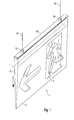
- escape sign light is provided for wire suspension and is accordingly attached via two wires 50 to a support, not shown, for example, the ceiling of a room or the like.
- a plurality of light sources in the form of LEDs are arranged, which are arranged side by side on an elongated board.
- the light of the LEDs is radiated from the top into a wedge-like design in cross-section 10.
- the light is forwarded according to the arrow shown within the light guide 10.
- the light guide 10 On its surface or the two opposite flat sides 11 and 12, the light guide 10 in a known manner structures over which incident light beams are deflected such that they leave the light guide 10 via one of these two sides 11, 12.
- the surface of the light guide 10 is additionally printed with a pictogram 2, via which the direction of an escape route is displayed.
- the solution according to the invention is concerned in particular with the problem of the reliable arrangement of the light sources in the region of the light coupling of the light-guiding element 10, the light sources being protected against external influences should.
- the LEDs should also be protected from other external influences, in particular from the penetration of dust and / or moisture.
- special measures are provided for this purpose, which are described in more detail below.
- the basic idea of the solution according to the invention is to embed the board with the LEDs in the light-guiding element 10 in the region of the light coupling and thereby to protect it against external influences. At the same time a reliable and effective coupling of the light is to be made possible in the light guide 10 still.
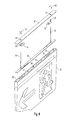
- a first measure required for this purpose consists in a special embodiment of the light-guiding element 10, which is described below with reference to FIGS. 2 to 4 should be explained. These figures show the light guide 10 in three different views.
- the peculiarity of the light-guiding element 10 consists in particular in that the light coupling-in area 13 is provided with a recess 20, in which sunk the LED board is later added.
- This recess 20 or recess is bounded in the case shown circumferentially by the light guide 10, has an elongated shape and preferably extends substantially over the entire length of the light guide 10 in order also over the entire length of time Lichteinkopplung and thus uniform illumination of the To enable pictogram 2.
- the bottom surface 21 of the recess 20 (see FIG. 8 ) then forms accordingly the actual light entry surface for the light guide 10.
- the board 30 with the LEDs 31 (see FIG. 10 ) is preferably not on the entire surface on this light entry surface 21.
- 21 spacers 22 are provided in the form of ribs or projections in the region of the bottom surface, on which the circuit board 30 rests.
- these spacers 22 ensure that the LEDs 31 are arranged at a defined distance from the light entry surface 21 and, accordingly, can effectively radiate the light into the light guide element 10, on the other hand, a secure mounting of the circuit board 30 is made possible without twisting or a Tilting is to be feared.
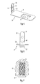
- FIGS. 5 and 6 Another special feature of the recess 20 is also that it is formed on its two side areas or side walls for special support of a clamping element, which is closer in the FIGS. 5 and 6 is shown and provided with the reference numeral 35.
- the task of this clamping element 35 is to fix the LED board 30 in an inserted into the recess 20 position.
- these clamping elements 35 are also the suspension of the lamp 1, as will be described in more detail below.
- the clamping elements 35 initially have a plate-like region 36, from which a downwardly bent tongue 37 is punched out. At one end of the plate-like portion 36, an upwardly directed web 38 is further formed, which is provided on the one hand at its two longitudinal sides with a toothing 39 and on the other hand has two holes 40. The function of the toothing 39 and the holes 40 will be explained in more detail below.
- These guide portions 25 are each formed on the two opposite side walls by a guide slot or a groove 26, in which the clamping element 35 is inserted laterally.
- the recess 20 is formed slightly enlarged adjacent to the guide portion 25 so that from the open side, the clamping member 35 can first be inserted from above and then laterally displaced until it fully engages the plate-like portion 36 in the two guide slots 26.
- a respectively formed at the beginning of the guide slot 26 and downwardly projecting projection 27 in this case ensures a fixation of the clamping member 35 in the longitudinal direction, so that it can no longer escape from the inserted position.
- the installation of the escape sign 1 is carried out according to the representation of FIG. 8 then by first of all the board 30 populated with the LEDs 31 being inserted into the recess 20 of the light-guiding element 10.
- the board 30 is already soldered to the two connection cables or wire ropes 50, which on the one hand the power supply and on the other hand, the suspension of the lamp. 1 serve.
- the two clamping elements 35 are then inserted in the manner described above and moved in the transverse direction, so that they engage in the guide portions 25.
- the two cables 50 are then passed under each of the clamping elements 35 and then threaded through the two openings 40 of the web 38, so that the in FIG. 9 shown arrangement results.
- a strain relief is realized, which allows a suspension of the lamp 1 to the lines for power supply, without affecting the connection to the LED board 30 is affected.
- the LED board 30 is reliably fixed in the recess 20 of the light-guiding element 10.
- a filling or potting material In order to enable a complete seal against external influences is now provided to fill the remaining space of the recess 20 with a filling or potting material.
- the use of a transparent, polyurethane-type potting compound is particularly suitable. This thus fills the remaining areas of the recess 20, in particular the above the board 30 lying areas such that a complete seal against the environment is achieved and, accordingly, a so-called. Protection can be achieved according to IP 42 or even higher.
- the recess 20 seen over its longitudinal direction is provided with several spacers 28 (see FIG. 2 ). These widenings 28 not only serve to allow the insertion of the clamping elements 35 in the procedure described above, but also allow the air to escape laterally during pouring of the potting compound. Ultimately, therefore, the recess 20 is actually completely filled, so even below the board 30 through the potting compound and the LED board is completely encased and effectively protected from external influences. The light coupling into the light guide 10 is not affected despite everything.
- a cover plate 60 preferably made of aluminum, is then placed from the upper side, which has two openings 61 for the passage of the suspension cables 50.
- the Kaschierhülsen 65 serve primarily optical purposes and have an internal thread 66, which screwing the sleeve 65 with the upwardly projecting beyond the potting compound web 38th of Clamping elements 35 allows.
- a centering ring 67 located at the lower end of the laminating sleeve 65, a correct centered seat of the cover plate 60 is made possible.
- FIG. 1 in perspective view as well as in FIG. 10 shown in cross-sectional configuration of the escape sign light according to the invention, in which the light emitted by the LEDs 31 light is effectively coupled into the light guide 10 and at the same time a reliable protection of the LED board 30 is guaranteed against external influences.
- the invention is not limited to escape sign luminaires.
- the light-guiding element can also be designed otherwise with regard to the alignment and configuration of the surfaces for emitting light.
Abstract
Description
- Die vorliegende Erfindung betrifft eine Anordnung zur Lichtabgabe gemäß dem Oberbegriff des Anspruchs 1, welche ein flächiges Lichtleitelement aufweist, in welches stirnseitig Licht eingekoppelt und über eine von der Stirnseite getrennte Flachseite abgestrahlt wird. Insbesondere betrifft die vorliegende Erfindung eine Rettungszeichenleuchte zum Anzeigen von Fluchtwegen oder dergleichen.
- Die Verwendung von Lichtleitelementen zur flächigen Lichtabgabe ist in der Beleuchtungstechnologie bereits seit langem bekannt. Das Grundprinzip derartiger Elemente beruht darauf, dass von einer oder mehreren Lichtquellen Licht über eine Schmalseite in das aus einem transparenten Material bestehende Element eingestrahlt wird. Über Reflexionen wird das Licht innerhalb des Lichtleitelements weitergeleitet und im Wesentlichen über das gesamte Element hinweg verteilt. Mittels spezieller sog. Lichtauskoppelstrukturen wird dann ein Teil des Lichts jeweils über eine im Wesentlichen senkrecht zur Lichteinkoppelfläche ausgerichtete Flachseite abgestrahlt. Der Vorteil bei der Verwendung derartiger Lichtleitelemente besteht darin, dass das von den Lichtquellen zur Verfügung gestellte Licht über eine verhältnismäßig große Fläche gleichmäßig abgegeben werden kann und trotz allem eine kompakte Anordnung erzielt wird. Demgegenüber weisen Beleuchtungsanordnungen, bei denen eine flächige Lichtabgabe mit Hilfe von Reflektoren oder dergleichen erzielt werden soll, eine deutlich höhere Bauform auf.
- Ein besonderes Anwendungsgebiet für derartige Anordnungen zur Lichtabgabe sind sog. Rettungszeichenleuchten. Es handelt sich hierbei um Leuchten, die dazu dienen, ein Piktogramm oder dergleichen hell erscheinen zu lassen, um Personen innerhalb eines Gebäudes einen Fluchtweg anzuzeigen, der ein einfaches und schnelles Verlassen des Gebäudes ermöglicht. Während früher die Piktogramme durch eine flächige Anordnung von Lichtquellen hinterleuchtet werden mussten, kann bei Verwendung der oben beschriebenen Lichtleittechnik nunmehr eine deutlich kompaktere Anordnung erzielt werden, da sich die Lichtquelle bzw. Lichtquellen lediglich an einer bestimmten Seite der Leuchte befinden müssen. Trotz allem wird mit Hilfe des Lichtelements sichergestellt, dass das Piktogramm über seine gesamte Fläche hinweg gleichmäßig hinterleuchtet wird und dementsprechend gut sichtbar ist. Ferner kann das Piktogramm bereits unmittelbar auf die als Lichtabstrahlfläche genutzte Flachseite des Lichtleitelements aufgetragen, z.B. aufgedruckt werden, sodass eine aus sehr wenigen Elementen bestehenden Leuchte realisiert werden kann.
- Ursprünglich wurden bei Beleuchtungsanordnungen, bei denen Lichtleitelemente der oben beschriebenen Art zum Einsatz kamen, längliche Lichtquellen insbesondere in Form von Leuchtstofflampen oder dergleichen eingesetzt, um Licht stirnseitig in das Lichtleitelement einzukoppeln. Zwischenzeitlich werden allerdings vermehrt auch punktförmige Lichtquellen, beispielsweise LEDs oder organische LEDs (sog. OLEDs) eingesetzt, welche dann nebeneinander angeordnet und auf die Lichteinkoppelfläche des Lichtleitelements ausgerichtet sind. LEDs weisen dabei den Vorteil auf, dass sie gegenüber herkömmlichen Lichtquellen energieeffizienter arbeiten und in der Regel auch eine höhere Betriebssicherheit aufweisen.
- Auf der anderen Seite müssen LEDs auch aufwendiger vor äußeren Einflüssen geschützt werden und es muss insbesondere Sorge dafür getragen werden, dass die LEDs bzw. die Platine, welche als Träger für die LEDs dient, nicht versehentlich durch einen Verbraucher bzw. Benutzer berührt wird, da dies aufgrund eventueller elektrostatischer Entladungen zu sog. ESD-Schäden führen kann. Auch das Eindringen von Feuchtigkeit oder dergleichen wirkt sich in diesem Fall sehr problematisch aus. In diesem Zusammenhang ist es zwar bekannt, zur Optimierung der Lichteinkopplung in der den LEDs zugewandten Stirnseite eines Lichtleitelements Vertiefungen zu bilden, in welche die LEDs teilweise hineinragen, allerdings ist auch bei dieser Lösung kein zufriedenstellender Schutz der LEDs bzw. der LED-Platine vor äußeren Einflüssen gewährleistet und es müssen aufwendige zusätzliche Maßnahmen getroffen werden, um den erforderlichen Schutz zu gewährleisten. Dies ist insbesondere auch dann der Fall, wenn ein Einsatz der Beleuchtungsanordnung in Bereichen geplant ist, in denen eine höhere Luftfeuchtigkeit vorliegt.
- Der vorliegenden Erfindung liegt deshalb die Aufgabenstellung zugrunde, eine Lösung anzugeben, bei der bei Einsatz eines flächigen Lichtleitelements ein zuverlässiger Schutz der Lichtquellen vor äußeren Einflüssen gewährleistet ist. Insbesondere soll sich die Anordnung dafür eignen, in Bereichen mit höherer Luftfeuchtigkeit eingesetzt zu werden, wobei trotz allem keine Beschädigung der Komponenten der Beleuchtungsanordnung zu befürchten ist.
- Diese Aufgabe wird durch eine Anordnung zur Lichtabgabe mit den Merkmalen des Anspruchs 1 gelöst. Vorteilhafte Weiterbildungen der Erfindungen sind Gegenstand der abhängigen Ansprüche.
- Bei der erfindungsgemäßen Lösung ist vorgesehen, dass die Lichtquellen, welche insbesondere in Form punktförmiger Lichtquellen, bevorzugt LEDs, vorliegen, gemeinsam mit einem entsprechenden Trägerelement für die Lichtquellen vertieft bzw. versenkt in dem Lichtleitelement angeordnet sind. Hierzu weist dieses an seiner den Lichteinkoppelbereich bildenden Schmalseite eine Ausnehmung auf, welche die Aufnahme der Lichtquellen gemeinsam mit ihrem Trägerelement ermöglicht. Dadurch, dass die zu schützenden Komponenten in einer entsprechenden Tasche oder Ausnehmung vollständig aufgenommen sind, können diese mit einfachen Mitteln vor äußeren Einflüssen geschützt werden. So lässt sich die verbleibende Öffnung zur Außenseite hin durch einfache Maßnahmen, welche nachfolgend noch näher beschrieben werden, abdichten.
- Erfindungsgemäß wird also eine Anordnung zur Lichtabgabe mit einem flächigen Lichtleitelement sowie mehreren im Wesentlichen punktförmigen Lichtquellen, insbesondere LEDs, vorgeschlagen, wobei die Lichtquellen an zumindest einer einen Lichteinkoppelbereich des Lichtleitelements bildenden Schmalseite angeordnet sind und das Lichtleitelement dazu ausgebildet ist, das von den Lichtquellen abgegebene und über den Lichteinkoppelbereich eingestrahlte Licht über eine im Wesentlichen senkrecht zu der Schmalseite angeordnete Flachseite abzustrahlen. Erfindungsgemäß ist vorgesehen, dass das Lichtleitelement an der den Einkoppelbereich bildenden Schmalseite eine Ausnehmung aufweist, in welcher die Lichtquellen gemeinsam mit einem Trägerelement für die Lichtquellen angeordnet sind.
- Vorzugsweise weist das Lichtleitelement innerhalb der Ausnehmung Rippen oder Vorsprünge auf, welche Auflagebereiche für das Trägerelement für die Lichtquellen bilden. Kommt beispielweise entsprechend einem bevorzugten Ausführungsbeispiel eine längliche LED-Platine zum Einsatz, so liegt diese auf diesen Rippen oder Vorsprüngen auf, was zur Folge hat, dass die LEDs in einer definierten Position bzgl. der eigentlichen Lichteinkoppelfläche des Lichtleitelements angeordnet sind. Insbesondere weisen sie einen geringfügigeren Abstand von dieser Fläche auf, der eine effiziente und optimale Lichteinkopplung gewährleistet. Darüber hinaus verhindern diese Auflagebereiche auch ein Verdrehen oder Kippen des Trägerelements.
- Die Halterung bzw. Fixierung des Trägerelements innerhalb der Ausnehmung des Lichtleitelements erfolgt vorzugsweise mit Hilfe von einem oder mehreren Klemmelementen. Diese können beispielsweise in einem bevorzugten Ausführungsbeispiel innerhalb der Ausnehmungen des Lichtleitelements verrastet werden und drücken dann von der den LEDs abgewandten Seite her gegen die Platine und arretieren diese zuverlässig innerhalb der Ausnehmung. Dabei können die Klemmelemente zusätzlich auch Mittel zum Befestigen von Aufhängungselementen für die Anordnung aufweisen, wobei durch diese Mittel vorzugsweise eine Zugentlastung des jeweiligen Aufhängungselements erzielt wird. Dies eröffnet insbesondere auch die Möglichkeit, die Zuführungsleitungen zur Stromversorgung der LEDs selbst zur Aufhängung der Anordnung zu nutzen, was zusätzlich zu einer sehr einfachen Ausgestaltung der erfindungsgemäßen Anordnung beiträgt.
- Ein besonders zuverlässiger Schutz der Lichtquellen vor äußeren Einflüssen wird gemäß der vorliegenden Erfindung insbesondere dann erzielt, wenn die Ausnehmung zur Aufnahme der Lichtquellen samt ihrem Trägerelement mit einer Guss- oder Füllmasse ausgefüllt ist. Nach dem Anordnen der Platine und Fixieren mit Hilfe der Klemmelemente in der Ausnehmung des Lichtleitelements kann also der verbleibende Hohlraum des Lichtleitelements ausgefüllt werden, sodass eine vollständige Abdichtung gegenüber äußeren Einflüssen erzielt wird. In diesem Fall ist dann zwar ein späterer Austausch der LED-Platine nicht mehr bzw. nur noch sehr schwer zu realisieren, aufgrund der Langlebigkeit der LED-Lichtquellen dürfte dies allerdings kein großes Problem darstellen.
- Das Lichtleitelement ist wie bereits erwähnt flächig ausgebildet, wobei hierunter allerdings nicht nur zu verstehen ist, dass dieses zwei parallel zueinander ausgerichtete Flachseiten aufweist. Die für die Lichtabgabe vorgesehenen Flachseiten könnten beispielsweise auch keilartig oder dergleichen ausgebildet sein. Auch eine leicht gewölbte bzw. gekrümmte Oberfläche wäre denkbar. Vorzugsweise ist die erfindungsgemäße Anordnung Bestandteil einer Rettungszeichenleuchte, wobei insbesondere das Lichtleitelement gleichzeitig auch als Träger für ein zu beleuchtendes Piktogramm dient.
- Nachfolgend soll die Erfindung anhand der beiliegenden Zeichnung näher erläutert werden. Es zeigen:
- Figur 1
- eine Rettungszeichenleuchte mit einer erfindungsgemäß ausgebildeten Anordnung zur Lichtabgabe;
- Figuren 2 bis 4
- unterschiedliche Ansichten eines erfindungsgemäßen Lichtleitelements;
- Figuren 5 und 6
- Ansichten eines zum Fixieren des Trägerelements für die Lichtquellen in dem Lichtleitelement genutzten Klemmelements;
- Figur 7
- eine vergrößerte Ansicht einer sog. Kaschierhülse zum oberen Abdecken des Zuführungsbereichs für ein Abhängungselement;
- Figur 8
- die erfindungsgemäße Rettungszeichenleuchte in Explosionsdarstellung;
- Figur 9
- eine vergrößerte Ansicht der Anordnung des Trägerelements für die Lichtquellen in der Ausnehmung des Lichtleitelements und
- Figur 10
- eine Schnittdarstellung der erfindungsgemäßen Rettungszeichenleuchte.
- Als bevorzugtes Ausführungsbeispiel der vorliegenden Erfindung wird nachfolgend eine Rettungszeichenleuchte beschrieben. Allerdings ist das erfindungsgemäße Konzept keinesfalls auf derartige Leuchtentypen beschränkt sondern kann grundsätzlich dann zum Einsatz kommen, wenn eine Lichtabgabe mit Hilfe von Lichtleitelementen erfolgen soll. Insbesondere können hierbei die Lichtquellen auch an mehreren Schmalseiten des Lichtleitelements entsprechend der erfindungsgemäßen Lösung angeordnet werden und eine Lichtabgabe kann über eine oder beide Flachseiten des Lichtleitelements erfolgen.
- Die in
Figur 1 in perspektivischer Ansicht dargestellte und allgemein mit dem Bezugszeichen 1 versehene Rettungszeichenleuchte ist zur Seilabhängung vorgesehen und wird dementsprechend über zwei Drahtseile 50 an einem nicht dargestellten Träger, beispielsweise der Decke eines Raums oder dergleichen befestigt. Innerhalb der Leuchte 1 sind mehrere Lichtquellen in Form von LEDs angeordnet, die nebeneinander auf einer länglichen Platine angeordnet sind. Das Licht der LEDs wird von der Oberseite her in ein im Querschnitt keilartig ausgebildetes Lichtleitelement 10 eingestrahlt. Durch Reflexionseffekte wird das Licht entsprechend dem dargestellten Pfeil innerhalb des Lichtleitelements 10 weitergeleitet. An seiner Oberfläche bzw. den beiden einander gegenüberliegenden Flachseiten 11 und 12 weist das Lichtleitelement 10 in bekannter Weise Strukturen auf, über welche auftreffende Lichtstrahlen derart umgelenkt werden, dass sie das Lichtleitelement 10 über eine dieser beiden Seiten 11, 12 verlassen. Eine derartige Technik ist bei transparenten Lichtleitelementen bereits hinlänglich bekannt. Im vorliegenden Fall der Verwendung in einer Rettungszeichenleuchte 1 ist zusätzlich die Oberfläche des Lichtleitelements 10 mit einem Piktogramm 2 bedruckt, über welches die Richtung eines Rettungsweges angezeigt wird. - Die erfindungsgemäße Lösung befasst sich insbesondere mit der Problematik der zuverlässigen Anordnung der Lichtquellen im Bereich der Lichteinkopplung des Lichtleitelements 10, wobei die Lichtquellen vor äußeren Einflüssen geschützt werden sollen. Dies bedeutet einerseits, dass ein versehentliches Berühren der LEDs bzw. der Platine mit den LEDs vermieden werden soll, um auf elektrostatische Entladungen zurückzuführende Schäden zu vermeiden. Andererseits sollen die LEDs auch vor anderen äußeren Einflüssen, insbesondere vor dem Eindringen von Staub und/oder Feuchtigkeit geschützt werden. Bei der erfindungsgemäßen Leuchte 1 sind hierzu besondere Maßnahmen vorgesehen, die nachfolgend näher beschrieben werden.
- Der Grundgedanke der erfindungsgemäßen Lösung besteht darin, die Platine mit den LEDs in das Lichtleitelement 10 im Bereich der Lichteinkopplung einzubetten und hierdurch vor äußeren Einflüssen zu schützen. Gleichzeitig soll nach wie vor eine zuverlässige und effektive Einkopplung des Lichts in das Lichtleitelement 10 ermöglicht werden.
- Eine erste hierzu erforderliche Maßnahme besteht in einer besonderen Ausgestaltung des Lichtleitelements 10, welche nachfolgend anhand der
Figuren 2 bis 4 erläutert werden soll. Diese Figuren zeigen dabei das Lichtleitelement 10 in drei verschiedenen Ansichten. - Die Besonderheit des Lichtleitelements 10 besteht dabei insbesondere darin, dass der Lichteinkoppelbereich 13 mit einer Ausnehmung 20 versehen ist, in welcher versenkt die LED-Platine später aufgenommen wird. Diese Ausnehmung 20 bzw. Vertiefung ist im dargestellten Fall umlaufend durch das Lichtleitelement 10 begrenzt, weist eine längliche Form auf und erstreckt sich vorzugsweise im Wesentlichen über die gesamte Länge des Lichtleitelements 10, um auch über die gesamte Länge hinweg eine Lichteinkopplung und damit gleichmäßige Ausleuchtung des Piktogramms 2 zu ermöglichen.
- Die Bodenfläche 21 der Ausnehmung 20 (siehe
Figur 8 ) bildet dann dementsprechend die eigentliche Lichteintrittsfläche für das Lichtleitelement 10. Die Platine 30 mit den LEDs 31 (sieheFigur 10 ) liegt allerdings vorzugsweise nicht vollflächig auf dieser Lichteintrittsfläche 21 auf. Stattdessen sind im Bereich der Bodenfläche 21 Distanzhalter 22 in Form von Rippen oder Vorsprüngen vorgesehen, auf denen die Platine 30 aufliegt. Einerseits sorgen diese Distanzhalter 22 dafür, dass die LEDs 31 in einem definierten Abstand zu der Lichteintrittsfläche 21 angeordnet sind und dementsprechend effektiv das Licht in das Lichtleitelement 10 einstrahlen können, anderseits wird hierdurch eine sichere Lagerung der Platine 30 ermöglicht, ohne dass ein Verdrehen oder ein Verkippen zu befürchten ist. - Eine weitere Besonderheit der Ausnehmung 20 besteht auch darin, dass diese an ihren beiden Seitenbereichen bzw. Seitenwänden zur speziellen Halterung eines Klemmelements ausgebildet ist, welches näher in den
Figuren 5 und 6 dargestellt und mit dem Bezugszeichen 35 versehen ist. Die Aufgabe dieses Klemmelements 35 ist es, die LED-Platine 30 in einer in die Ausnehmung 20 eingelegten Position zu fixieren. Ferner dienen diese Klemmelemente 35 auch der Aufhängung der Leuchte 1, wie nachfolgend noch näher beschrieben wird. - Die Klemmelemente 35 weisen dabei zunächst einen plattenartigen Bereich 36 auf, aus dem eine nach unten ausgebogene Zunge 37 ausgestanzt ist. An einem Ende des plattenartigen Bereichs 36 ist ferner ein nach oben gerichteter Steg 38 ausgebildet, welcher einerseits an seinen beiden Längsseiten mit einer Verzahnung 39 versehen ist und andererseits zwei Löcher 40 aufweist. Die Funktion der Verzahnung 39 sowie der Löcher 40 wird nachfolgend noch näher erläutert.
- Wie insbesondere der Darstellung von
Figur 2 entnommen werden kann, weist die Ausnehmung 20 des Lichtleitelements 10 in den Seitenwänden zwei Führungs- bzw. Aufnahmeabschnitte 25 für die Lagerung der Klemmelemente 35 auf. Diese Führungsabschnitte 25 sind jeweils an den zwei einander gegenüberliegenden Seitenwänden durch einen Führungsschlitz bzw. eine Nut 26 gebildet, in welche das Klemmelement 35 seitlich eingeschoben wird. Hierzu ist benachbart zu dem Führungsbereich 25 die Ausnehmung 20 leicht vergrößert ausgebildet, sodass von der offenen Seite her das Klemmelement 35 zunächst von oben eingesetzt und dann seitlich verschoben werden kann, bis es mit dem plattenartigen Bereich 36 vollständig in die beiden Führungsschlitze 26 eingreift. Ein jeweils am Beginn des Führungsschlitzes 26 ausgebildeter und nach unten vorstehender Vorsprung 27 sorgt hierbei für eine Fixierung des Klemmelements 35 in Längsrichtung, sodass dieses nicht mehr aus der eingesetzten Position entweichen kann. Gleichzeitig drückt in diesem Zustand dann das Klemmelement 35 mit der nach unten ausgebogenen Zunge 37 gegen die Oberseite der LED-Platine 30 und fixiert diese auf diese Weise in der in die Ausnehmung 20 eingelegten Position. Aufgrund dieser Andruckkraft der Zunge 37 wird das Klemmelement 35 nach oben gepresst und dementsprechend hinter der nach unten vorstehenden Rastnase bzw. dem Vorsprung 27 des Führungsbereichs 25 fixiert. - Die Montage der Rettungszeichenleuchte 1 erfolgt entsprechend der Darstellung von
Figur 8 dann dadurch, dass zunächst die mit den LEDs 31 bestückte Platine 30 in die Ausnehmung 20 des Lichtleitelements 10 eingesetzt wird. In diesem Zustand ist die Platine 30 auch bereits mit den beiden Anschlusskabeln bzw. Drahtseilen 50 verlötet, welche einerseits der Stromversorgung und andererseits der Aufhängung der Leuchte 1 dienen. Nach Einlegen der Platine 30 in die Ausnehmung 20 werden dann in der oben beschriebenen Weise die beiden Klemmelemente 35 eingesetzt und in Querrichtung verschoben, sodass sie in die Führungsbereichen 25 einrasten. Die beiden Seile 50 werden dann jeweils unter den Klemmelementen 35 hindurchgeführt und anschließend durch die beiden Öffnungen 40 des Stegs 38 gefädelt, sodass sich die inFigur 9 dargestellte Anordnung ergibt. Auf diesem Wege wird mit Hilfe der Klemmelemente 35 auch eine Zugentlastung realisiert, welche eine Aufhängung der Leuchte 1 an den Leitungen zur Stromzuführung ermöglicht, ohne dass hierbei die Anbindung an die LED-Platine 30 beeinträchtigt wird. - In diesem Zustand ist die LED-Platine 30 zuverlässig in der Ausnehmung 20 des Lichtleitelements 10 fixiert. Um eine möglichst vollständige Abdichtung gegenüber äußeren Einflüssen zu ermöglichen ist nun vorgesehen, den verbleibenden Freiraum der Ausnehmung 20 mit einem Füll- oder Vergussmaterial auszufüllen. Es bietet sich hierbei insbesondere die Verwendung einer transparenten, polyurethanartigen Vergussmasse an. Diese füllt also die restlichen Bereiche der Ausnehmung 20, insbesondere die oberhalb der Platine 30 liegenden Bereiche derart aus, dass eine vollständige Abdichtung gegenüber der Umgebung erzielt wird und dementsprechend eine sog. Schutzart gemäß IP 42 oder sogar noch höher erzielt werden kann. Da bei dem Ausfüllen der Ausnehmung 20 mit der Vergussmasse evtl. entstehende Lufteinschlüsse die Lichteinkopplung in das Lichtleitelement 10 massiv beeinträchtigen könnten, ist die Ausnehmung 20 über ihre Längsrichtung hinweg gesehen mit mehreren Verbreiterungen 28 versehen (siehe
Figur 2 ). Diese Verbreiterungen 28 dienen nicht nur dazu, das Einsetzen der Klemmelemente 35 in der zuvor beschriebenen Vorgehensweise zu ermöglichen, sondern erlauben auch, dass während des Eingießens der Vergussmasse die Luft seitlich entweichen kann. Letztendlich wird also die Ausnehmung 20 tatsächlich vollständig, also auch unterhalb der Platine 30 durch die Vergussmasse ausgefüllt und die LED-Platine ist vollständig ummantelt und effektiv vor äußeren Einflüssen geschützt. Die Lichteinkopplung in das Lichtleitelement 10 wird trotz allem nicht beeinträchtigt. - Nach dem Vergießen bzw. Auffüllen der Ausnehmung 20 wird dann noch von der Oberseite her ein vorzugsweise aus Aluminium bestehendes Abdeckblech 60 aufgelegt, welches zwei Öffnungen 61 zum Hindurchführen der Aufhängungsseile 50 aufweist. Mit Hilfe zweier Kaschierhülsen 65, welche im Schnitt in
Figur 7 gezeigt sind, erfolgt dann eine abschließende Arretierung des Abdeckblechs 60 an der Oberseite des Lichtleitelements 10. Die Kaschierhülsen 65 dienen in erster Linie optischen Zwecken und weisen ein Innengewinde 66 auf, welches ein Verschrauben der Hülse 65 mit dem nach oben über die Vergussmasse hinausragenden Steg 38 des Klemmelements 35 ermöglicht. Über einen am unteren Ende der Kaschierhülse 65 befindlichen Zentrierring 67 wird ein korrekter zentrierter Sitz des Abdeckblechs 60 ermöglicht. - Letztendlich ergibt sich also dann die in
Figur 1 in perspektivischer Ansicht sowie inFigur 10 in Schnittdarstellung gezeigte Ausgestaltung der erfindungsgemäßen Rettungszeichenleuchte, bei der das von den LEDs 31 emittierte Licht effektiv in das Lichtleitelement 10 eingekoppelt wird und gleichzeitig ein zuverlässiger Schutz der LED-Platine 30 vor äußeren Einflüssen gewährleistet ist. - Wie bereits erwähnt ist die Erfindung nicht auf Rettungszeichenleuchten beschränkt. Ferner kann das Lichtleitelement hinsichtlich der Ausrichtung und Ausgestaltung der Flächen zur Lichtabgabe auch anderweitig ausgebildet sein.
Claims (10)
- Anordnung zur Lichtabgabe mit einem flächigen Lichtleitelement (10) sowie mehreren im Wesentlichen punktförmigen Lichtquellen (31), welche an zumindest einer einen Lichteinkoppelbereich (13) des Lichtleitelements (10) bildenden Schmalseite angeordnet sind,
wobei das Lichtleitelement (10) dazu ausgebildet ist, das von den Lichtquellen (31) abgegebene und über den Lichteinkoppelbereich (13) eingestrahlte Licht über eine im wesentlichen senkrecht zu der Schmalseite angeordnete Flachseite (11, 12) abzustrahlen,
dadurch gekennzeichnet,
dass das Lichtleitelement (10) an der den Lichteinkoppelbereich (13) bildenden Schmalseite eine Ausnehmung (20) aufweist, in welcher die Lichtquellen (31) gemeinsam mit einem Trägerelement (30) für die Lichtquellen (31) angeordnet sind. - Anordnung zur Lichtabgabe nach Anspruch 1,
dadurch gekennzeichnet,
dass das Lichtleitelement (10) in der Ausnehmung (20), insbesondere an einer Bodenfläche (21) Rippen (22) oder Vorsprünge aufweist, welche Auflagebereiche für das Trägerelement (30) für die Lichtquellen (31) bilden. - Anordnung nach Anspruch 1 oder 2,
dadurch gekennzeichnet,
dass das Trägerelement (30) für die Lichtquellen (31) mit Hilfe von einem oder mehreren Klemmelementen (35) in der Ausnehmung (20) fixiert ist. - Anordnung nach Anspruch 3,
dadurch gekennzeichnet,
dass die Ausnehmung (20) an ihren Seitenwänden Mittel zum Verrasten bzw. Fixieren des Klemmelements (35) aufweist. - Anordnung nach Anspruch 3 oder 4,
dadurch gekennzeichnet,
dass das oder die Klemmelemente (35) Mittel zum Befestigen von Aufhängungselementen (50) für die Anordnung aufweisen. - Anordnung nach Anspruch 5,
dadurch gekennzeichnet,
dass das oder die Klemmelemente (35) einen aus der Ausnehmung (20) hervorstehenden Steg (38) aufweisen, der Öffnungen (40) zum Durchführen und Zugentlasten eines seilartigen Aufhängungselements (50) aufweist. - Anordnung nach einem der vorherigen Ansprüche,
dadurch gekennzeichnet,
dass die Ausnehmung (20) mit einer Verguss- oder Füllmasse ausgefüllt ist. - Anordnung nach einem der vorherigen Ansprüche,
dadurch gekennzeichnet,
dass das Lichtleitelement (10) keilartig ausgebildet ist. - Anordnung nach einem der vorherigen Ansprüche,
dadurch gekennzeichnet,
dass diese Bestandteil einer Rettungszeichenleuchte (1) ist. - Lichtleitelement (10) zur Verwendung in einer Anordnung zur Lichtabgabe mit mehreren im Wesentlichen punktförmigen Lichtquellen (31), welche an zumindest einer einen Lichteinkoppelbereich (13) des Lichtleitelements (10) bildenden Schmalseite angeordnet sind,
wobei das Lichtleitelement (10) dazu ausgebildet ist, das von den Lichtquellen (31) abgegebene und über den Lichteinkoppelbereich (13) eingestrahlte Licht über eine im wesentlichen senkrecht zu der Schmalseite angeordnete Flachseite (11, 12) abzustrahlen,
dadurch gekennzeichnet,
dass das Lichtleitelement (10) an der den Lichteinkoppelbereich (13) bildenden Schmalseite eine Ausnehmung (20) aufweist, welche zur Aufnahme der Lichtquellen (31) gemeinsam mit einem Trägerelement (30) für die Lichtquellen (31) ausgebildet ist.
Applications Claiming Priority (1)
| Application Number | Priority Date | Filing Date | Title |
|---|---|---|---|
| DE202012101244U DE202012101244U1 (de) | 2012-04-05 | 2012-04-05 | Anordnung zur Lichtabgabe mit flächigem Lichtleitelement |
Publications (3)
| Publication Number | Publication Date |
|---|---|
| EP2648178A2 true EP2648178A2 (de) | 2013-10-09 |
| EP2648178A3 EP2648178A3 (de) | 2014-04-23 |
| EP2648178B1 EP2648178B1 (de) | 2015-06-10 |
Family
ID=47998321
Family Applications (1)
| Application Number | Title | Priority Date | Filing Date |
|---|---|---|---|
| EP13161950.4A Active EP2648178B1 (de) | 2012-04-05 | 2013-04-02 | Anordnung zur Lichtabgabe mit flächigem Lichtleitelement |
Country Status (2)
| Country | Link |
|---|---|
| EP (1) | EP2648178B1 (de) |
| DE (1) | DE202012101244U1 (de) |
Cited By (2)
| Publication number | Priority date | Publication date | Assignee | Title |
|---|---|---|---|---|
| EP4064262A1 (de) | 2021-02-19 | 2022-09-28 | Zumtobel Lighting GmbH | Rettungszeichenleuchte mit rettungswegbeleuchtung |
| EP4297003A1 (de) | 2022-06-20 | 2023-12-27 | Zumtobel Lighting GmbH | Rettungszeichenleuchte mit zusätzlicher rettungswegbeleuchtung |
Families Citing this family (3)
| Publication number | Priority date | Publication date | Assignee | Title |
|---|---|---|---|---|
| DE102015219947A1 (de) * | 2015-10-14 | 2017-04-20 | Zf Friedrichshafen Ag | Schaltungsträger und Verfahren zur Herstellung desselben |
| DE102022108996A1 (de) | 2022-04-13 | 2023-10-19 | Zumtobel Lighting Gmbh | Lichtleitelement beispielsweise für rettungszeichenleuchte |
| DE202022101995U1 (de) | 2022-04-13 | 2023-07-18 | Zumtobel Lighting Gmbh | Lichtleitelement für Rettungszeichenleuchte |
Family Cites Families (8)
| Publication number | Priority date | Publication date | Assignee | Title |
|---|---|---|---|---|
| DE29514090U1 (de) * | 1995-09-04 | 1995-11-16 | Schulz Juergen Dipl Ing | Gehäuselose Rettungszeichenleuchte |
| SE512755C2 (sv) * | 1997-07-08 | 2000-05-08 | Lisol Scandinavia Ab | Belyst visningsenhet samt metod för tillverkning av densamma |
| DE29912986U1 (de) * | 1999-07-26 | 2000-05-11 | Renic Anton | Zeichenartige Leuchtmarke |
| DE19945495A1 (de) * | 1999-09-22 | 2001-04-05 | Daniel Wustlich | Ausgeleuchtetes plattenartiges Element |
| DE10123006B4 (de) * | 2001-05-12 | 2014-07-10 | P.E.R. Flucht- Und Rettungsleitsysteme Gmbh | Leuchtvorrichtung zur Erzeugung einer aktiv nachleuchtenden Signalfläche |
| DE20114561U1 (de) * | 2001-09-04 | 2003-01-23 | Ceag Sicherheitstechnik Gmbh | Scheibenleuchte |
| DE102004055337A1 (de) * | 2003-11-17 | 2005-06-23 | Russler, Theodor | Illuminationsmittel, insbesondere für den Außenbereich, wie Gebäudeaußenflächen und Gartenanlagen |
| KR20100077677A (ko) * | 2008-12-29 | 2010-07-08 | 삼성전자주식회사 | 백라이트 유닛 및 이를 갖는 액정표시장치 |
-
2012
- 2012-04-05 DE DE202012101244U patent/DE202012101244U1/de not_active Expired - Lifetime
-
2013
- 2013-04-02 EP EP13161950.4A patent/EP2648178B1/de active Active
Non-Patent Citations (1)
| Title |
|---|
| None |
Cited By (2)
| Publication number | Priority date | Publication date | Assignee | Title |
|---|---|---|---|---|
| EP4064262A1 (de) | 2021-02-19 | 2022-09-28 | Zumtobel Lighting GmbH | Rettungszeichenleuchte mit rettungswegbeleuchtung |
| EP4297003A1 (de) | 2022-06-20 | 2023-12-27 | Zumtobel Lighting GmbH | Rettungszeichenleuchte mit zusätzlicher rettungswegbeleuchtung |
Also Published As
| Publication number | Publication date |
|---|---|
| EP2648178A3 (de) | 2014-04-23 |
| DE202012101244U1 (de) | 2013-07-09 |
| EP2648178B1 (de) | 2015-06-10 |
Similar Documents
| Publication | Publication Date | Title |
|---|---|---|
| EP2738447B1 (de) | Regalbeleuchtungsvorrichtung | |
| EP2151899B1 (de) | Lichtbandsystem | |
| EP2648178B1 (de) | Anordnung zur Lichtabgabe mit flächigem Lichtleitelement | |
| EP2650865B1 (de) | Anordnung zur Lichtabgabe mit flächigem Lichtleitelement | |
| EP2650866B1 (de) | Gehäuse zur Aufnahme eines Betriebsgeräts zum Betreiben einer oder mehrerer Lichtquellen | |
| EP2177823B1 (de) | LED-Einbaumodul, Beleuchtungsanordnung sowie Decken- oder Wandkonstruktion mit diesem LED-Einbaumodul | |
| EP2994693B1 (de) | Abdeckungselement für flächenleuchte | |
| EP2711750B1 (de) | LED-Leuchte mit Lichtleiterplatte | |
| EP2924337B1 (de) | Leuchte mit einem lichtleiter zur erzeugung von entblendetem, teilflächigen licht | |
| EP2642470B1 (de) | Plattenförmiges Lichtleitelement und Leuchte mit Lichtleitelement | |
| EP2472178B1 (de) | Einbauleuchte | |
| EP3366991A1 (de) | Geräteträger für leuchte | |
| EP2816543B1 (de) | Befestigungsprofil und Leuchtvorrichtung | |
| EP2631537B1 (de) | Leuchte mit einem länglichen Gehäuse und Anbauelement hierfür | |
| EP2176583B1 (de) | Leuchte mit raster zur lichtabgabe | |
| EP2674667B1 (de) | Leuchteneinheit für eine LED-Leuchte, sowie LED-Leuchte | |
| DE10107153B4 (de) | Flächige Rettungszeichenleuchte mit einer im wesentlichen viereckigen Displayscheibe | |
| DE202022101995U1 (de) | Lichtleitelement für Rettungszeichenleuchte | |
| EP3329178B1 (de) | Lichtleiterelement | |
| DE102006007175B4 (de) | Leuchte, insbesondere Seitenleuchte eines Fahrzeugs, sowie Reflektoreinheit | |
| AT16410U1 (de) | Anordnung zur flächigen Lichtabgabe | |
| DE202013103456U1 (de) | Pendelleuchte mit einer Lichtquelle zur Erzeugung einer indirekten Beleuchtung | |
| CH709411B1 (de) | Leuchtelement mit OLED. |
Legal Events
| Date | Code | Title | Description |
|---|---|---|---|
| PUAI | Public reference made under article 153(3) epc to a published international application that has entered the european phase |
Free format text: ORIGINAL CODE: 0009012 |
|
| AK | Designated contracting states |
Kind code of ref document: A2 Designated state(s): AL AT BE BG CH CY CZ DE DK EE ES FI FR GB GR HR HU IE IS IT LI LT LU LV MC MK MT NL NO PL PT RO RS SE SI SK SM TR |
|
| AX | Request for extension of the european patent |
Extension state: BA ME |
|
| PUAL | Search report despatched |
Free format text: ORIGINAL CODE: 0009013 |
|
| AK | Designated contracting states |
Kind code of ref document: A3 Designated state(s): AL AT BE BG CH CY CZ DE DK EE ES FI FR GB GR HR HU IE IS IT LI LT LU LV MC MK MT NL NO PL PT RO RS SE SI SK SM TR |
|
| AX | Request for extension of the european patent |
Extension state: BA ME |
|
| RIC1 | Information provided on ipc code assigned before grant |
Ipc: G09F 13/22 20060101ALN20140319BHEP Ipc: G09F 13/04 20060101ALN20140319BHEP Ipc: G09F 13/18 20060101AFI20140319BHEP |
|
| 17P | Request for examination filed |
Effective date: 20140825 |
|
| RBV | Designated contracting states (corrected) |
Designated state(s): AL AT BE BG CH CY CZ DE DK EE ES FI FR GB GR HR HU IE IS IT LI LT LU LV MC MK MT NL NO PL PT RO RS SE SI SK SM TR |
|
| REG | Reference to a national code |
Ref country code: DE Ref legal event code: R079 Ref document number: 502013000725 Country of ref document: DE Free format text: PREVIOUS MAIN CLASS: G09F0013220000 Ipc: G09F0013180000 |
|
| GRAP | Despatch of communication of intention to grant a patent |
Free format text: ORIGINAL CODE: EPIDOSNIGR1 |
|
| RIC1 | Information provided on ipc code assigned before grant |
Ipc: G09F 13/22 20060101ALN20141029BHEP Ipc: G09F 13/04 20060101ALN20141029BHEP Ipc: G09F 13/18 20060101AFI20141029BHEP |
|
| INTG | Intention to grant announced |
Effective date: 20141126 |
|
| GRAS | Grant fee paid |
Free format text: ORIGINAL CODE: EPIDOSNIGR3 |
|
| GRAA | (expected) grant |
Free format text: ORIGINAL CODE: 0009210 |
|
| AK | Designated contracting states |
Kind code of ref document: B1 Designated state(s): AL AT BE BG CH CY CZ DE DK EE ES FI FR GB GR HR HU IE IS IT LI LT LU LV MC MK MT NL NO PL PT RO RS SE SI SK SM TR |
|
| REG | Reference to a national code |
Ref country code: GB Ref legal event code: FG4D Free format text: NOT ENGLISH |
|
| REG | Reference to a national code |
Ref country code: CH Ref legal event code: EP |
|
| REG | Reference to a national code |
Ref country code: AT Ref legal event code: REF Ref document number: 731183 Country of ref document: AT Kind code of ref document: T Effective date: 20150715 Ref country code: CH Ref legal event code: NV Representative=s name: WEINMANN ZIMMERLI, CH |
|
| REG | Reference to a national code |
Ref country code: DE Ref legal event code: R096 Ref document number: 502013000725 Country of ref document: DE |
|
| REG | Reference to a national code |
Ref country code: IE Ref legal event code: FG4D Free format text: LANGUAGE OF EP DOCUMENT: GERMAN |
|
| PG25 | Lapsed in a contracting state [announced via postgrant information from national office to epo] |
Ref country code: ES Free format text: LAPSE BECAUSE OF FAILURE TO SUBMIT A TRANSLATION OF THE DESCRIPTION OR TO PAY THE FEE WITHIN THE PRESCRIBED TIME-LIMIT Effective date: 20150610 Ref country code: LT Free format text: LAPSE BECAUSE OF FAILURE TO SUBMIT A TRANSLATION OF THE DESCRIPTION OR TO PAY THE FEE WITHIN THE PRESCRIBED TIME-LIMIT Effective date: 20150610 Ref country code: FI Free format text: LAPSE BECAUSE OF FAILURE TO SUBMIT A TRANSLATION OF THE DESCRIPTION OR TO PAY THE FEE WITHIN THE PRESCRIBED TIME-LIMIT Effective date: 20150610 Ref country code: NO Free format text: LAPSE BECAUSE OF FAILURE TO SUBMIT A TRANSLATION OF THE DESCRIPTION OR TO PAY THE FEE WITHIN THE PRESCRIBED TIME-LIMIT Effective date: 20150910 |
|
| REG | Reference to a national code |
Ref country code: NL Ref legal event code: MP Effective date: 20150610 |
|
| PG25 | Lapsed in a contracting state [announced via postgrant information from national office to epo] |
Ref country code: LV Free format text: LAPSE BECAUSE OF FAILURE TO SUBMIT A TRANSLATION OF THE DESCRIPTION OR TO PAY THE FEE WITHIN THE PRESCRIBED TIME-LIMIT Effective date: 20150610 Ref country code: GR Free format text: LAPSE BECAUSE OF FAILURE TO SUBMIT A TRANSLATION OF THE DESCRIPTION OR TO PAY THE FEE WITHIN THE PRESCRIBED TIME-LIMIT Effective date: 20150911 Ref country code: BG Free format text: LAPSE BECAUSE OF FAILURE TO SUBMIT A TRANSLATION OF THE DESCRIPTION OR TO PAY THE FEE WITHIN THE PRESCRIBED TIME-LIMIT Effective date: 20150910 Ref country code: RS Free format text: LAPSE BECAUSE OF FAILURE TO SUBMIT A TRANSLATION OF THE DESCRIPTION OR TO PAY THE FEE WITHIN THE PRESCRIBED TIME-LIMIT Effective date: 20150610 |
|
| PG25 | Lapsed in a contracting state [announced via postgrant information from national office to epo] |
Ref country code: EE Free format text: LAPSE BECAUSE OF FAILURE TO SUBMIT A TRANSLATION OF THE DESCRIPTION OR TO PAY THE FEE WITHIN THE PRESCRIBED TIME-LIMIT Effective date: 20150610 |
|
| PG25 | Lapsed in a contracting state [announced via postgrant information from national office to epo] |
Ref country code: CZ Free format text: LAPSE BECAUSE OF FAILURE TO SUBMIT A TRANSLATION OF THE DESCRIPTION OR TO PAY THE FEE WITHIN THE PRESCRIBED TIME-LIMIT Effective date: 20150610 Ref country code: PL Free format text: LAPSE BECAUSE OF FAILURE TO SUBMIT A TRANSLATION OF THE DESCRIPTION OR TO PAY THE FEE WITHIN THE PRESCRIBED TIME-LIMIT Effective date: 20150610 Ref country code: IS Free format text: LAPSE BECAUSE OF FAILURE TO SUBMIT A TRANSLATION OF THE DESCRIPTION OR TO PAY THE FEE WITHIN THE PRESCRIBED TIME-LIMIT Effective date: 20151010 Ref country code: PT Free format text: LAPSE BECAUSE OF FAILURE TO SUBMIT A TRANSLATION OF THE DESCRIPTION OR TO PAY THE FEE WITHIN THE PRESCRIBED TIME-LIMIT Effective date: 20151012 Ref country code: SK Free format text: LAPSE BECAUSE OF FAILURE TO SUBMIT A TRANSLATION OF THE DESCRIPTION OR TO PAY THE FEE WITHIN THE PRESCRIBED TIME-LIMIT Effective date: 20150610 Ref country code: RO Free format text: LAPSE BECAUSE OF NON-PAYMENT OF DUE FEES Effective date: 20150610 |
|
| REG | Reference to a national code |
Ref country code: DE Ref legal event code: R097 Ref document number: 502013000725 Country of ref document: DE |
|
| PLBE | No opposition filed within time limit |
Free format text: ORIGINAL CODE: 0009261 |
|
| STAA | Information on the status of an ep patent application or granted ep patent |
Free format text: STATUS: NO OPPOSITION FILED WITHIN TIME LIMIT |
|
| REG | Reference to a national code |
Ref country code: FR Ref legal event code: PLFP Year of fee payment: 4 |
|
| PG25 | Lapsed in a contracting state [announced via postgrant information from national office to epo] |
Ref country code: IT Free format text: LAPSE BECAUSE OF FAILURE TO SUBMIT A TRANSLATION OF THE DESCRIPTION OR TO PAY THE FEE WITHIN THE PRESCRIBED TIME-LIMIT Effective date: 20150610 Ref country code: DK Free format text: LAPSE BECAUSE OF FAILURE TO SUBMIT A TRANSLATION OF THE DESCRIPTION OR TO PAY THE FEE WITHIN THE PRESCRIBED TIME-LIMIT Effective date: 20150610 |
|
| 26N | No opposition filed |
Effective date: 20160311 |
|
| PG25 | Lapsed in a contracting state [announced via postgrant information from national office to epo] |
Ref country code: SI Free format text: LAPSE BECAUSE OF FAILURE TO SUBMIT A TRANSLATION OF THE DESCRIPTION OR TO PAY THE FEE WITHIN THE PRESCRIBED TIME-LIMIT Effective date: 20150610 |
|
| PG25 | Lapsed in a contracting state [announced via postgrant information from national office to epo] |
Ref country code: BE Free format text: LAPSE BECAUSE OF NON-PAYMENT OF DUE FEES Effective date: 20160430 |
|
| PG25 | Lapsed in a contracting state [announced via postgrant information from national office to epo] |
Ref country code: LU Free format text: LAPSE BECAUSE OF FAILURE TO SUBMIT A TRANSLATION OF THE DESCRIPTION OR TO PAY THE FEE WITHIN THE PRESCRIBED TIME-LIMIT Effective date: 20160402 |
|
| REG | Reference to a national code |
Ref country code: IE Ref legal event code: MM4A |
|
| REG | Reference to a national code |
Ref country code: FR Ref legal event code: PLFP Year of fee payment: 5 |
|
| PG25 | Lapsed in a contracting state [announced via postgrant information from national office to epo] |
Ref country code: IE Free format text: LAPSE BECAUSE OF NON-PAYMENT OF DUE FEES Effective date: 20160402 |
|
| PG25 | Lapsed in a contracting state [announced via postgrant information from national office to epo] |
Ref country code: NL Free format text: LAPSE BECAUSE OF FAILURE TO SUBMIT A TRANSLATION OF THE DESCRIPTION OR TO PAY THE FEE WITHIN THE PRESCRIBED TIME-LIMIT Effective date: 20150610 Ref country code: SE Free format text: LAPSE BECAUSE OF FAILURE TO SUBMIT A TRANSLATION OF THE DESCRIPTION OR TO PAY THE FEE WITHIN THE PRESCRIBED TIME-LIMIT Effective date: 20150610 |
|
| REG | Reference to a national code |
Ref country code: FR Ref legal event code: PLFP Year of fee payment: 6 |
|
| PG25 | Lapsed in a contracting state [announced via postgrant information from national office to epo] |
Ref country code: SM Free format text: LAPSE BECAUSE OF FAILURE TO SUBMIT A TRANSLATION OF THE DESCRIPTION OR TO PAY THE FEE WITHIN THE PRESCRIBED TIME-LIMIT Effective date: 20150610 Ref country code: HU Free format text: LAPSE BECAUSE OF FAILURE TO SUBMIT A TRANSLATION OF THE DESCRIPTION OR TO PAY THE FEE WITHIN THE PRESCRIBED TIME-LIMIT; INVALID AB INITIO Effective date: 20130402 Ref country code: CY Free format text: LAPSE BECAUSE OF FAILURE TO SUBMIT A TRANSLATION OF THE DESCRIPTION OR TO PAY THE FEE WITHIN THE PRESCRIBED TIME-LIMIT Effective date: 20150610 |
|
| PG25 | Lapsed in a contracting state [announced via postgrant information from national office to epo] |
Ref country code: TR Free format text: LAPSE BECAUSE OF FAILURE TO SUBMIT A TRANSLATION OF THE DESCRIPTION OR TO PAY THE FEE WITHIN THE PRESCRIBED TIME-LIMIT Effective date: 20150610 Ref country code: MC Free format text: LAPSE BECAUSE OF FAILURE TO SUBMIT A TRANSLATION OF THE DESCRIPTION OR TO PAY THE FEE WITHIN THE PRESCRIBED TIME-LIMIT Effective date: 20150610 Ref country code: MK Free format text: LAPSE BECAUSE OF FAILURE TO SUBMIT A TRANSLATION OF THE DESCRIPTION OR TO PAY THE FEE WITHIN THE PRESCRIBED TIME-LIMIT Effective date: 20150610 Ref country code: HR Free format text: LAPSE BECAUSE OF FAILURE TO SUBMIT A TRANSLATION OF THE DESCRIPTION OR TO PAY THE FEE WITHIN THE PRESCRIBED TIME-LIMIT Effective date: 20150610 Ref country code: MT Free format text: LAPSE BECAUSE OF FAILURE TO SUBMIT A TRANSLATION OF THE DESCRIPTION OR TO PAY THE FEE WITHIN THE PRESCRIBED TIME-LIMIT Effective date: 20150610 |
|
| PG25 | Lapsed in a contracting state [announced via postgrant information from national office to epo] |
Ref country code: AL Free format text: LAPSE BECAUSE OF FAILURE TO SUBMIT A TRANSLATION OF THE DESCRIPTION OR TO PAY THE FEE WITHIN THE PRESCRIBED TIME-LIMIT Effective date: 20150610 |
|
| REG | Reference to a national code |
Ref country code: DE Ref legal event code: R084 Ref document number: 502013000725 Country of ref document: DE |
|
| PGFP | Annual fee paid to national office [announced via postgrant information from national office to epo] |
Ref country code: CH Payment date: 20190426 Year of fee payment: 7 |
|
| PGFP | Annual fee paid to national office [announced via postgrant information from national office to epo] |
Ref country code: DE Payment date: 20190514 Year of fee payment: 15 |
|
| REG | Reference to a national code |
Ref country code: CH Ref legal event code: PL |
|
| REG | Reference to a national code |
Ref country code: AT Ref legal event code: MM01 Ref document number: 731183 Country of ref document: AT Kind code of ref document: T Effective date: 20200402 |
|
| PG25 | Lapsed in a contracting state [announced via postgrant information from national office to epo] |
Ref country code: LI Free format text: LAPSE BECAUSE OF NON-PAYMENT OF DUE FEES Effective date: 20200430 Ref country code: CH Free format text: LAPSE BECAUSE OF NON-PAYMENT OF DUE FEES Effective date: 20200430 Ref country code: AT Free format text: LAPSE BECAUSE OF NON-PAYMENT OF DUE FEES Effective date: 20200402 |
|
| P01 | Opt-out of the competence of the unified patent court (upc) registered |
Effective date: 20230530 |
|
| PGFP | Annual fee paid to national office [announced via postgrant information from national office to epo] |
Ref country code: FR Payment date: 20230421 Year of fee payment: 11 |
|
| PGFP | Annual fee paid to national office [announced via postgrant information from national office to epo] |
Ref country code: GB Payment date: 20230418 Year of fee payment: 11 |