EP2647860B1 - Bushing for coupling with a component - Google Patents
Bushing for coupling with a component Download PDFInfo
- Publication number
- EP2647860B1 EP2647860B1 EP13001552.2A EP13001552A EP2647860B1 EP 2647860 B1 EP2647860 B1 EP 2647860B1 EP 13001552 A EP13001552 A EP 13001552A EP 2647860 B1 EP2647860 B1 EP 2647860B1
- Authority
- EP
- European Patent Office
- Prior art keywords
- bushing
- component
- socket
- positive locking
- locking means
- Prior art date
- Legal status (The legal status is an assumption and is not a legal conclusion. Google has not performed a legal analysis and makes no representation as to the accuracy of the status listed.)
- Active
Links
- 238000010168 coupling process Methods 0.000 title description 2
- 230000008878 coupling Effects 0.000 title 1
- 238000005859 coupling reaction Methods 0.000 title 1
- 238000000034 method Methods 0.000 claims description 28
- 230000008569 process Effects 0.000 claims description 11
- 238000003754 machining Methods 0.000 claims description 3
- 230000003811 curling process Effects 0.000 claims description 2
- 238000007493 shaping process Methods 0.000 claims 3
- 238000006073 displacement reaction Methods 0.000 claims 1
- 238000005304 joining Methods 0.000 description 8
- 230000008901 benefit Effects 0.000 description 6
- 238000005096 rolling process Methods 0.000 description 6
- 238000005260 corrosion Methods 0.000 description 3
- 230000007797 corrosion Effects 0.000 description 3
- 230000008961 swelling Effects 0.000 description 3
- 238000004519 manufacturing process Methods 0.000 description 2
- 238000003780 insertion Methods 0.000 description 1
- 230000037431 insertion Effects 0.000 description 1
- 238000009434 installation Methods 0.000 description 1
- 230000005012 migration Effects 0.000 description 1
- 238000013508 migration Methods 0.000 description 1
- 238000003825 pressing Methods 0.000 description 1
- 230000002035 prolonged effect Effects 0.000 description 1
- 230000008439 repair process Effects 0.000 description 1
Images
Classifications
-
- F—MECHANICAL ENGINEERING; LIGHTING; HEATING; WEAPONS; BLASTING
- F16—ENGINEERING ELEMENTS AND UNITS; GENERAL MEASURES FOR PRODUCING AND MAINTAINING EFFECTIVE FUNCTIONING OF MACHINES OR INSTALLATIONS; THERMAL INSULATION IN GENERAL
- F16L—PIPES; JOINTS OR FITTINGS FOR PIPES; SUPPORTS FOR PIPES, CABLES OR PROTECTIVE TUBING; MEANS FOR THERMAL INSULATION IN GENERAL
- F16L5/00—Devices for use where pipes, cables or protective tubing pass through walls or partitions
-
- F—MECHANICAL ENGINEERING; LIGHTING; HEATING; WEAPONS; BLASTING
- F16—ENGINEERING ELEMENTS AND UNITS; GENERAL MEASURES FOR PRODUCING AND MAINTAINING EFFECTIVE FUNCTIONING OF MACHINES OR INSTALLATIONS; THERMAL INSULATION IN GENERAL
- F16C—SHAFTS; FLEXIBLE SHAFTS; ELEMENTS OR CRANKSHAFT MECHANISMS; ROTARY BODIES OTHER THAN GEARING ELEMENTS; BEARINGS
- F16C35/00—Rigid support of bearing units; Housings, e.g. caps, covers
- F16C35/02—Rigid support of bearing units; Housings, e.g. caps, covers in the case of sliding-contact bearings
-
- B—PERFORMING OPERATIONS; TRANSPORTING
- B21—MECHANICAL METAL-WORKING WITHOUT ESSENTIALLY REMOVING MATERIAL; PUNCHING METAL
- B21K—MAKING FORGED OR PRESSED METAL PRODUCTS, e.g. HORSE-SHOES, RIVETS, BOLTS OR WHEELS
- B21K25/00—Uniting components to form integral members, e.g. turbine wheels and shafts, caulks with inserts, with or without shaping of the components
-
- B—PERFORMING OPERATIONS; TRANSPORTING
- B23—MACHINE TOOLS; METAL-WORKING NOT OTHERWISE PROVIDED FOR
- B23P—METAL-WORKING NOT OTHERWISE PROVIDED FOR; COMBINED OPERATIONS; UNIVERSAL MACHINE TOOLS
- B23P11/00—Connecting or disconnecting metal parts or objects by metal-working techniques not otherwise provided for
- B23P11/005—Connecting or disconnecting metal parts or objects by metal-working techniques not otherwise provided for by expanding or crimping
-
- F—MECHANICAL ENGINEERING; LIGHTING; HEATING; WEAPONS; BLASTING
- F16—ENGINEERING ELEMENTS AND UNITS; GENERAL MEASURES FOR PRODUCING AND MAINTAINING EFFECTIVE FUNCTIONING OF MACHINES OR INSTALLATIONS; THERMAL INSULATION IN GENERAL
- F16B—DEVICES FOR FASTENING OR SECURING CONSTRUCTIONAL ELEMENTS OR MACHINE PARTS TOGETHER, e.g. NAILS, BOLTS, CIRCLIPS, CLAMPS, CLIPS OR WEDGES; JOINTS OR JOINTING
- F16B17/00—Connecting constructional elements or machine parts by a part of or on one member entering a hole in the other and involving plastic deformation
- F16B17/006—Connecting constructional elements or machine parts by a part of or on one member entering a hole in the other and involving plastic deformation of rods or tubes to sheets or plates
-
- F—MECHANICAL ENGINEERING; LIGHTING; HEATING; WEAPONS; BLASTING
- F16—ENGINEERING ELEMENTS AND UNITS; GENERAL MEASURES FOR PRODUCING AND MAINTAINING EFFECTIVE FUNCTIONING OF MACHINES OR INSTALLATIONS; THERMAL INSULATION IN GENERAL
- F16C—SHAFTS; FLEXIBLE SHAFTS; ELEMENTS OR CRANKSHAFT MECHANISMS; ROTARY BODIES OTHER THAN GEARING ELEMENTS; BEARINGS
- F16C33/00—Parts of bearings; Special methods for making bearings or parts thereof
- F16C33/02—Parts of sliding-contact bearings
- F16C33/04—Brasses; Bushes; Linings
- F16C33/06—Sliding surface mainly made of metal
- F16C33/08—Attachment of brasses, bushes or linings to the bearing housing
-
- F—MECHANICAL ENGINEERING; LIGHTING; HEATING; WEAPONS; BLASTING
- F16—ENGINEERING ELEMENTS AND UNITS; GENERAL MEASURES FOR PRODUCING AND MAINTAINING EFFECTIVE FUNCTIONING OF MACHINES OR INSTALLATIONS; THERMAL INSULATION IN GENERAL
- F16L—PIPES; JOINTS OR FITTINGS FOR PIPES; SUPPORTS FOR PIPES, CABLES OR PROTECTIVE TUBING; MEANS FOR THERMAL INSULATION IN GENERAL
- F16L5/00—Devices for use where pipes, cables or protective tubing pass through walls or partitions
- F16L5/02—Sealing
- F16L5/10—Sealing by using sealing rings or sleeves only
-
- F—MECHANICAL ENGINEERING; LIGHTING; HEATING; WEAPONS; BLASTING
- F16—ENGINEERING ELEMENTS AND UNITS; GENERAL MEASURES FOR PRODUCING AND MAINTAINING EFFECTIVE FUNCTIONING OF MACHINES OR INSTALLATIONS; THERMAL INSULATION IN GENERAL
- F16C—SHAFTS; FLEXIBLE SHAFTS; ELEMENTS OR CRANKSHAFT MECHANISMS; ROTARY BODIES OTHER THAN GEARING ELEMENTS; BEARINGS
- F16C2226/00—Joining parts; Fastening; Assembling or mounting parts
- F16C2226/50—Positive connections
- F16C2226/52—Positive connections with plastic deformation, e.g. caulking or staking
-
- F—MECHANICAL ENGINEERING; LIGHTING; HEATING; WEAPONS; BLASTING
- F16—ENGINEERING ELEMENTS AND UNITS; GENERAL MEASURES FOR PRODUCING AND MAINTAINING EFFECTIVE FUNCTIONING OF MACHINES OR INSTALLATIONS; THERMAL INSULATION IN GENERAL
- F16C—SHAFTS; FLEXIBLE SHAFTS; ELEMENTS OR CRANKSHAFT MECHANISMS; ROTARY BODIES OTHER THAN GEARING ELEMENTS; BEARINGS
- F16C2300/00—Application independent of particular apparatuses
- F16C2300/02—General use or purpose, i.e. no use, purpose, special adaptation or modification indicated or a wide variety of uses mentioned
-
- Y—GENERAL TAGGING OF NEW TECHNOLOGICAL DEVELOPMENTS; GENERAL TAGGING OF CROSS-SECTIONAL TECHNOLOGIES SPANNING OVER SEVERAL SECTIONS OF THE IPC; TECHNICAL SUBJECTS COVERED BY FORMER USPC CROSS-REFERENCE ART COLLECTIONS [XRACs] AND DIGESTS
- Y10—TECHNICAL SUBJECTS COVERED BY FORMER USPC
- Y10T—TECHNICAL SUBJECTS COVERED BY FORMER US CLASSIFICATION
- Y10T29/00—Metal working
- Y10T29/49—Method of mechanical manufacture
- Y10T29/49995—Shaping one-piece blank by removing material
Definitions
- the invention relates to a method for avoiding relative movement between a socket and a component coupled to the socket.
- a large number of differently designed sockets are known from the prior art.
- the sockets can be inserted into a component or placed on a component.
- the sockets should be attached to the components in such a way that there is no relative movement between the socket and the component.
- a relative movement between the bushing and the component can be caused by swelling or changing loads on the bushing and/or the component.
- Bushings that move at the joint lead to increased wear at the joint or, when using corrosive materials, very often to increased corrosion at the joint.
- Various methods are already known by which the joining force between the bushing and the component is increased in order to prevent the aforementioned relative movement.
- bushings are thermally inserted to protect components from wear or corrosion.
- the joining force is limited due to the technical limitations in the temperature difference between the bushing and the component before joining.
- a disadvantage of the thermal joining process is that the achievable joining force is not sufficient to reliably prevent the socket from rotating or moving during prolonged, swelling or changing loads during operation.
- the socket can be glued to the component.
- the object of the invention is to provide a method for avoiding a relative movement between the bushing and the component, which does not have at least the disadvantages mentioned above.
- a method for avoiding a relative movement between a bushing, in particular a bearing bushing, and a component coupled to the bushing (2).
- the form-fitting means is formed and brought into form-fitting relationship with the component.
- the joining force between the socket and the component increases, so that socket migration is prevented.
- the positive locking means is produced on the bushing using a caulking process or a rolling process.
- a caulking process is understood to mean a process in which the positive locking means is produced using a caulking tool.
- a caulking method according to the invention a simultaneous deformation of the positive locking means of the bushing can be realized.
- a rolling method is understood to mean a method in which the positive locking means is produced by a rolling tool.
- the socket has a socket body and a Head section which extends transversely, in particular vertically, from the socket body.
- the positive locking means is provided at an end of the socket body facing away from the head section.
- the head section can be formed in one piece with the socket body. Providing a socket with a head section offers the advantage that when the socket is coupled to the component, the head section itself serves to avoid a relative movement between the socket and the component in at least one direction, in particular in a longitudinal direction of the socket.
- the head section and/or the socket body can be coupled directly to the component.
- the bushing Before machining the bushing to produce the form-fitting part, the bushing is placed on a component or inserted into a component.
- the groove can be created on an end face of the socket. Forming a groove in the bushing offers the advantage that the form-fitting means can be easily deformed to create a form-fitting connection.
- the socket body is the part of the socket that is not processed when producing the form-fitting means.
- the form-fitting means can be designed as a section protruding from the socket body. Furthermore, a recess which is counter-shaped to the form-fitting means can be created in the component and into which the form-fitting means can penetrate. This offers the advantage that the risk of relative movement between the bushing and the component is further reduced.
- the same tool is used to produce and deform the positive locking means.
- the caulking tool or the rolling tool is used to deform the form-fitting means.
- the tool exerts a force on the form-fitting means in the direction of the component.
- the socket can be placed on a component or inserted into a component.
- the bushing that is placed on a component such as a pin, mandrel, shaft or the like
- the bushing that is inserted into a component is referred to as the internal bushing.
- the direction of deformation of the form-fitting part depends on whether the bushing is an external or internal bushing. In both cases, the positive locking means is deformed, in particular bent, in the direction of the component.
- the bushings can be made of different materials and can be used for different purposes, such as for wear protection, corrosion protection or repair procedures of load introduction points or attachment points between different components.
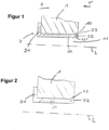
- Socket 2 shown is coupled to a component 1.
- the socket 2 is partially inserted into a recess 11 of the component 1.
- the socket 2 has a head section 21 and a socket body 20.
- the head section 21 extends essentially vertically from the socket body 20 and is in contact with the component 1.
- the socket body 20 is also in contact with the component 1.
- the socket 2 has two positive locking means in the form of two protruding sections 23, 23 '.
- the two Positive locking means are separated from one another by a groove 22 and protrude from the socket body 20.
- the groove 22 extends from the end face of the bushing 2 towards the head section 21.
- the bushing body 20 is considered to be the part of the bushing 2 that is not processed during the production of the groove 22.
- a recess 10 is provided in the component 1, which is counter-shaped to the positive locking means or to the protruding section 23, 23 '.
- FIG 1 a state is shown in which no deformation of the protruding portion 23, 23 'occurs. This means that the bushing 2 can still move in a longitudinal direction P' of the bushing 2, the movement in the longitudinal direction P' being directed opposite to the movement in the longitudinal direction.
- Figure 2 a state is shown in which a deformation of the positive locking means has occurred.
- the positive locking means or the protruding section 23 located closer to the component 1 is shaped in such a way that it penetrates into the recess 10 and comes into contact with the component 1. As a result, the forming results in a positive connection between the bushing 2 and the component 1.
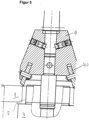
- FIG 5 A processing device for carrying out the curling process is shown.
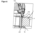
- FIG 6 An enlarged portion of the area of engagement of the device tool with the bushing is shown.
- the processing device has a carrier 3 for carrying the bushing 2 and the component 1.
- the processing device has a tool holder 4 which holds a tool 40.
- the tool 40 can rotate about an axis of rotation and also carry out a lifting movement along a longitudinal axis of the processing device.
- the tool holder can be a column drill.
- the joining process of the socket 2 with the component 1 is explained below.
- the recess 10 is created in the component 1 before the coupling process with the socket 2. This can be done by the in Figure 5 shown processing device or another device.
- Socket 2 is then coupled with component 1. To do this, the socket 2 is inserted into the recess 11 of the component. After the insertion process, the tool 40 is used to create the groove 22 and thus the positive locking means in the socket 2.
- the same tool 40 exerts a force in the direction of the head section 20 of the socket, so that the positive locking means or the protruding section 23 is deformed.
- the positive locking means is bent and penetrates into the recess 10 of the component 1 and comes into contact with it, whereby a positive lock is created between the bushing 2 and the component 1.
- the bushing 2 is coupled to the component 1 in such a way that a relative movement between the bushing 2 and the component 1 is not possible.
Landscapes
- Engineering & Computer Science (AREA)
- General Engineering & Computer Science (AREA)
- Mechanical Engineering (AREA)
- Automatic Assembly (AREA)
- Mutual Connection Of Rods And Tubes (AREA)
- Connector Housings Or Holding Contact Members (AREA)
- Connection Of Plates (AREA)
Description
Die Erfindung betrifft ein Verfahren zum Vermeiden einer Relativbewegung zwischen einer Buchse und einem mit der Buchse gekoppelten Bauteil.The invention relates to a method for avoiding relative movement between a socket and a component coupled to the socket.
Aus dem Stand der Technik ist eine Vielzahl von unterschiedlich ausgebildeten Buchsen bekannt. Die Buchsen können in ein Bauteil eingesetzt oder auf ein Bauteil gesetzt werden. Dabei soll die Befestigung der Buchsen an den Bauteilen derart erfolgen, dass keine Relativbewegung zwischen der Buchse und dem Bauteil erfolgt. Eine Relativbewegung zwischen der Buchse und dem Bauteil kann durch schwellende oder wechselnde Belastungen der Buchse und/oder des Bauteils hervorgerufen werden. Buchsen, die sich an der Fügestelle bewegen, führen zu erhöhten Verschleiß an der Fügestelle oder bei der Verwendung von korrosiven Werkstoffen sehr häufig zu erhöhter Korrosion an der Fügestelle. Es sind bereits verschiedene Verfahren bekannt, mittels denen die Fügekraft zwischen der Buchse und dem Bauteil erhöht wird, um die zuvor genannte Relativbewegung zu verhindern.A large number of differently designed sockets are known from the prior art. The sockets can be inserted into a component or placed on a component. The sockets should be attached to the components in such a way that there is no relative movement between the socket and the component. A relative movement between the bushing and the component can be caused by swelling or changing loads on the bushing and/or the component. Bushings that move at the joint lead to increased wear at the joint or, when using corrosive materials, very often to increased corrosion at the joint. Various methods are already known by which the joining force between the bushing and the component is increased in order to prevent the aforementioned relative movement.
So ist es bekannt, dass Buchsen zum Verschleißschutz oder Korrosionsschutz von Bauteilen thermisch eingefügt werden. Dabei ist die Fügekraft aufgrund der technischen Einschränkungen bei der Temperaturdifferenz zwischen der Buchse und dem Bauteil vor dem Fügen begrenzt. Zudem besteht ein Nachteil des thermischen Fügeverfahrens darin, dass die erreichbare Fügekraft nicht ausreicht, um ein Drehen oder Wandern der Buchse bei längerer schwellender oder wechselnder Lasteinwirkung im Betrieb sicher zu verhindern.It is known that bushings are thermally inserted to protect components from wear or corrosion. The joining force is limited due to the technical limitations in the temperature difference between the bushing and the component before joining. In addition, a disadvantage of the thermal joining process is that the achievable joining force is not sufficient to reliably prevent the socket from rotating or moving during prolonged, swelling or changing loads during operation.
Ferner ist bekannt, die Buchse mittels einer hydraulischen Vorrichtung in ein Bauteil einzupressen oder auf ein Bauteil aufzupressen. Nachteilig an diesem Verfahren ist jedoch, dass eine speziell für diesen Zweck ausgebildete Vorrichtung zum Verpressen der Buchse benötigt wird.It is also known to press the bushing into a component or onto a component using a hydraulic device. However, the disadvantage of this method is that a device designed specifically for this purpose is required for pressing the bushing.
Des Weiteren ist bekannt, dass die Buchse mit dem Bauteil verklebt werden kann.It is also known that the socket can be glued to the component.
Mit diesem Befestigungsverfahren können jedoch nur geringe Fügekräfte erzielt werden, so dass der Einsatzbereich des Befestigungsverfahrens auf Einsatzfälle der Buchse beschränkt bleibt, bei denen auf diese keine hohen Lasten wirken.With this fastening method, however, only low joining forces can be achieved, so that the area of application of the fastening method remains limited to applications of the socket in which no high loads act on it.
In Dokument
Die Aufgabe der Erfindung besteht darin, ein Verfahren zum Vermeiden einer Relativbewegung zwischen der Buchse und dem Bauteil vorzusehen, das wenigstens die zuvor genannten Nachteile nicht aufweist.The object of the invention is to provide a method for avoiding a relative movement between the bushing and the component, which does not have at least the disadvantages mentioned above.
Die Aufgabe wird durch das Verfahren nach Anspruch 1 gelöst. Eine vorteilhafte Ausgestaltung der Erfindung ist Gegenstand des Unteranspruchs 2.The task is solved by the method according to
Erfindungsgemäß ist ein Verfahren zum Vermeiden einer Relativbewegung zwischen einer Buchse, insbesondere eine Lagerbuchse, und einem mit der Buchse (2) gekoppelten Bauteil vorgesehen.According to the invention, a method is provided for avoiding a relative movement between a bushing, in particular a bearing bushing, and a component coupled to the bushing (2).
Zum Vermeiden einer Relativbewegung zwischen der Buchse und dem Bauteil wird das Formschlussmittel umgeformt, und in Formschluss mit dem Bauteil gebracht.To avoid a relative movement between the bushing and the component, the form-fitting means is formed and brought into form-fitting relationship with the component.
Aufgrund der Formschlussverbindung zwischen der Buchse und dem Bauteil wird die Gefahr einer Relativbewegung zwischen der Buchse und dem Bauteil aufgrund von schwellenden oder wechselnden Belastungen signifikant reduziert.Due to the positive connection between the bushing and the component, the risk of relative movement between the bushing and the component due to swelling or changing loads is significantly reduced.
Insbesondere erhöht sich in Kombination mit dem oben genannten thermischen Installationsverfahren die Fügekraft zwischen der Buchse und dem Bauteil, so dass ein Buchsenwandern verhindert wird.In particular, in combination with the above-mentioned thermal installation method, the joining force between the socket and the component increases, so that socket migration is prevented.
Erfindungsgemäß wird das Formschlussmittel auf der Buchse mittels eines Einstemmverfahrens oder eines Einrollverfahrens hergestellt.According to the invention, the positive locking means is produced on the bushing using a caulking process or a rolling process.
Im Sinne der Erfindung wird unter einem Einstemmverfahren ein Verfahren verstanden, bei dem das Formschlussmittel durch ein Stemmwerkzeug hergestellt wird. Beim erfindungsgemäßen Einstemmverfahren kann eine zeitgleiche Verformung des Formschlussmittels der Buchse realisiert werden. Im Sinne der Erfindung wird als Einrollverfahren ein derartiges Verfahren verstanden, bei dem das Formschlussmittel durch ein Einrollwerkzeug hergestellt wird.For the purposes of the invention, a caulking process is understood to mean a process in which the positive locking means is produced using a caulking tool. With the caulking method according to the invention, a simultaneous deformation of the positive locking means of the bushing can be realized. For the purposes of the invention, a rolling method is understood to mean a method in which the positive locking means is produced by a rolling tool.
Die Buchse weist einen Buchsenkörper und einen Kopfabschnitt auf, der sich quer, insbesondere senkrecht, von dem Buchsenkörper erstreckt. Das Formschlussmittel ist an einem von dem Kopfabschnitt abgewandten Ende des Buchsenkörpers vorgesehen.The socket has a socket body and a Head section which extends transversely, in particular vertically, from the socket body. The positive locking means is provided at an end of the socket body facing away from the head section.
Der Kopfabschnitt kann einstückig mit dem Buchsenkörper ausgebildet sein. Das Vorsehen einer Buchse mit Kopfabschnitt bietet den Vorteil, dass bei der Kopplung der Buchse mit dem Bauteil der Kopfabschnitt selbst zum Vermeiden einer Relativbewegung zwischen der Buchse und dem Bauteil in wenigstens einer Richtung, insbesondere in einer Längsrichtung der Buchse, dient. Dabei kann der Kopfabschnitt und/oder der Buchsenkörper unmittelbar mit dem Bauteil gekoppelt sein.The head section can be formed in one piece with the socket body. Providing a socket with a head section offers the advantage that when the socket is coupled to the component, the head section itself serves to avoid a relative movement between the socket and the component in at least one direction, in particular in a longitudinal direction of the socket. The head section and/or the socket body can be coupled directly to the component.
Vor einem Bearbeiten der Buchse zum Herstellen des Formschlussteils wird die Buchse auf ein Bauteil aufgesetzt oder in ein Bauteil eingesetzt.Before machining the bushing to produce the form-fitting part, the bushing is placed on a component or inserted into a component.
Dies bietet den Vorteil, dass nach dem Bearbeitungsvorgang und dem plastischen keine weiteren Arbeitsschritte mehr notwendig sind.This offers the advantage that no further work steps are necessary after the processing and plastic processing.
Beim Herstellen des Formschlussmittels wird eine Nut in die Buchse geformt.When producing the form-fitting means, a groove is formed in the bushing.
Die Nut kann an einer Stirnfläche der Buchse erzeugt werden. Das Formen einer Nut in der Buchse bietet den Vorteil, dass das Formschlussmittels zum Erzeugen einer Formschlussverbindung leicht verformt werden kann. Dabei ist der Buchsenkörper der Teil der Buchse, der bei der Erzeugung des Formschlussmittels nicht bearbeitet wird.The groove can be created on an end face of the socket. Forming a groove in the bushing offers the advantage that the form-fitting means can be easily deformed to create a form-fitting connection. The socket body is the part of the socket that is not processed when producing the form-fitting means.
Dabei kann das Formschlussmittel als ein von dem Buchsenkörper hervorstehender Abschnitt ausgebildet sein. Ferner kann in das Bauteil eine dem Formschlussmittel gegengeformte Aussparung erzeugt werden, in die das Formschlussmittel eindringen kann. Dies bietet den Vorteil, dass sich die Gefahr einer Relativbewegung zwischen der Buchse und dem Bauteil weiter verringert.The form-fitting means can be designed as a section protruding from the socket body. Furthermore, a recess which is counter-shaped to the form-fitting means can be created in the component and into which the form-fitting means can penetrate. This offers the advantage that the risk of relative movement between the bushing and the component is further reduced.
Erfindungsgemäß wird zum Herstellen und Verformen des Formschlussmittels das gleiche Werkzeug eingesetzt.According to the invention, the same tool is used to produce and deform the positive locking means.
Dies bietet den Vorteil, dass der Herstellvorgang des Formschlussmittels auf der Buchse schnell und somit kostengünstig erfolgt. So wird bei der Herstellung der Buchse mit dem Einstemmverfahren oder dem Einrollverfahren das Stemmwerkzeug bzw. das Einrollwerkzeug dazu benutzt, das Formschlussmittel zu verformen. Dazu wird durch das Werkzeug eine Kraft auf das Formschlussmittel in Richtung zum Bauteil ausgeübt.This offers the advantage that the manufacturing process of the positive locking means on the bushing takes place quickly and therefore cost-effectively. When producing the bushing using the caulking process or the rolling process, the caulking tool or the rolling tool is used to deform the form-fitting means. For this purpose, the tool exerts a force on the form-fitting means in the direction of the component.
Die Buchse kann auf ein Bauteil aufgesetzt oder in ein Bauteil eingesetzt werden.The socket can be placed on a component or inserted into a component.
Im Folgenden wird daher die Buchse, die auf ein Bauteil, wie z.B. ein Pin, Dorn, Schaft oder dergleichen, aufgesetzt wird, als außenliegende Buchse und die Buchse, die in eine Bauteil eingesetzt wird, als innenliegende Buchse bezeichnet. Dementsprechend hängt die Verformrichtung des Formschlussteils davon, ob es sich bei der Buchse um eine außenliegende oder innenliegende Buchse handelt. In beiden Fällen wird das Formschlussmittel jeweils in Richtung zum Bauteil verformt, insbesondere gebogen.In the following, the bushing that is placed on a component, such as a pin, mandrel, shaft or the like, is referred to as the external bushing and the bushing that is inserted into a component is referred to as the internal bushing. Accordingly, the direction of deformation of the form-fitting part depends on whether the bushing is an external or internal bushing. In both cases, the positive locking means is deformed, in particular bent, in the direction of the component.
Die Buchsen können aus verschiedenen Materialien gefertigt sein und können zu verschiedenen Zwecken Einsatz finden, wie z.B. zum Verschleißschutz, Korrosionsschutz oder Reperaturverfahren von Lasteinleitungspunkten bzw. Befestigungspunkten zwischen verschiedenen Bauteilen.The bushings can be made of different materials and can be used for different purposes, such as for wear protection, corrosion protection or repair procedures of load introduction points or attachment points between different components.
Mit der vorliegenden Erfindung wird die Längsbewegung durch Formschluß und die Relativbewegung durch Reibschluß verhindert. Schließlich kann ein vorhandenes Spiel kompensiert werden.With the present invention, the longitudinal movement is prevented by positive locking and the relative movement is prevented by frictional locking. Finally, an existing backlash can be compensated.
Weitere Einzelheiten und Vorteile der Erfindung sollen nun anhand der in den Zeichnungen dargestellten Ausführungsbeispiele näher erläutert werden.Further details and advantages of the invention will now be explained in more detail using the exemplary embodiments shown in the drawings.
Dabei zeigen:
- Fig. 1
- eine mit einem Bauteil gekoppelte Buchse vor einem Verformvorgang des Formschlussmittels,
- Fig. 2
- eine mit dem Bauteil gekoppelte Buchse nach einem Verformvorgang des Formschlussmittels,
- Fig. 5
- eine Vorrichtung zur Durchführung eines erfindungsgemäßen Einrollverfahrens,
- Fig. 6
- einen vergrößerten Abschnitt der in
Fig. 5 gezeigten Vorrichtung.
- Fig. 1
- a bushing coupled to a component before a deformation process of the positive locking means,
- Fig. 2
- a bushing coupled to the component after a deformation process of the positive locking means,
- Fig. 5
- a device for carrying out a rolling process according to the invention,
- Fig. 6
- an enlarged section of the in
Fig. 5 device shown.
Die in
Die Buchse 2 weist an ihrem dem Kopfabschnitt 21 abgewandten Ende zwei Formschlussmittel in Form von zwei hervorstehenden Abschnitten 23, 23' auf. Die beiden Formschlussmittel werden durch eine Nut 22 voneinander getrennt und ragen von dem Buchsenkörper 20 vor. Die Nut 22 erstreckt sich von der Stirnseite der Buchse 2 in Richtung zum Kopfabschnitt 21. Der Buchsenkörper 20 wird als der Teil der Buchse 2 angesehen, der bei der Herstellung der Nut 22 nicht bearbeitet wird.At its end facing away from the
In dem Bauteil 1 ist eine Aussparung 10 vorgesehen, die zum Formschlussmittel bzw. zum hervorstehenden Abschnitt 23, 23' gegengeformt ist.A
Dabei wird in
In
Im Folgenden wird der Fügevorgang der Buchse 2 mit dem Bauteil 1 erläutert. In das Bauteil 1 wird vor dem Koppelvorgang mit der Buchse 2 die Aussparung 10 erzeugt. Dies kann durch die in
Letztendlich wird durch das gleiche Werkzeug 40 eine Kraft in Richtung zum Kopfabschnitt 20 der Buchse ausgeübt, so dass das Formschlussmittel bzw. der hervorstehende Abschnitt 23 verformt wird. Dabei wird das Formschlussmittel gebogen und dringt in die Aussparung 10 des Bauteils 1 ein und gelangt mit diesem in Kontakt, wodurch ein Formschluss zwischen der Buchse 2 und dem Bauteil 1 erzeugt wird. Im Anschluss an den Verformvorgang ist die Buchse 2 derart mit dem Bauteil 1 gekoppelt, dass eine Relativbewegung zwischen der Buchse 2 und dem Bauteil 1 nicht möglich ist.Ultimately, the
Claims (2)
- Method for preventing relative displacement between a bushing (2) and a component (1) coupled to the bushing (2), comprising the following steps:- machining the bushing (2) to produce a form-fitting means, wherein the bushing (2) comprises a bushing body (20) and a head portion (21) which extends transversely, in particular perpendicularly, to the bushing body (20), and wherein the form-fitting means (23, 23') is provided at an end of the bushing body (20) remote from the head portion (21), and- shaping of the form-fit means (23, 23') so that a form-fit connection exists between the bushing (2) and the component (1) after the shaping operation,wherein a groove (22) is formed in the bushing (2) for producing the form-fitting means (23, 23') and wherein the bushing body (20) is the part of the bushing (2) which is not machined when forming the groove (22),characterized in thatthe form-fit means (23, 23') is manufactured by means of a curling process or a mortising process, andthat the shaping of the form-fit means is carried out by means of the same machining device and the same tool (40), by means of which the form-fit means (23, 23') is produced.
- Method as claimed in claim 1, characterized in that a recess (10) is produced in the component (1) which is counter-formed to the form-fit means (23, 23').
Applications Claiming Priority (1)
| Application Number | Priority Date | Filing Date | Title |
|---|---|---|---|
| DE102012007010A DE102012007010A1 (en) | 2012-04-05 | 2012-04-05 | Socket for coupling with a component |
Publications (3)
| Publication Number | Publication Date |
|---|---|
| EP2647860A2 EP2647860A2 (en) | 2013-10-09 |
| EP2647860A3 EP2647860A3 (en) | 2017-12-27 |
| EP2647860B1 true EP2647860B1 (en) | 2023-12-06 |
Family
ID=48087338
Family Applications (1)
| Application Number | Title | Priority Date | Filing Date |
|---|---|---|---|
| EP13001552.2A Active EP2647860B1 (en) | 2012-04-05 | 2013-03-26 | Bushing for coupling with a component |
Country Status (4)
| Country | Link |
|---|---|
| US (1) | US9366363B2 (en) |
| EP (1) | EP2647860B1 (en) |
| CN (1) | CN103362918B (en) |
| DE (1) | DE102012007010A1 (en) |
Families Citing this family (1)
| Publication number | Priority date | Publication date | Assignee | Title |
|---|---|---|---|---|
| DE102013223005A1 (en) | 2013-11-12 | 2015-05-13 | Brose Fahrzeugteile Gmbh & Co. Kg, Coburg | Method for connecting a socket to a component |
Citations (5)
| Publication number | Priority date | Publication date | Assignee | Title |
|---|---|---|---|---|
| GB2190435A (en) * | 1986-05-08 | 1987-11-18 | Johnson Electric Ind Mfg | Sintered bearings |
| JPS62199522U (en) * | 1986-06-09 | 1987-12-18 | ||
| DE19609252C1 (en) * | 1996-02-28 | 1997-01-16 | Brose Fahrzeugteile | Component connection and method and device for their production |
| JP2005034857A (en) * | 2003-07-17 | 2005-02-10 | Aisin Seiki Co Ltd | Caulking member and caulking method |
| US20050058375A1 (en) * | 2003-09-16 | 2005-03-17 | Benq Corporation | Bushing structure |
Family Cites Families (19)
| Publication number | Priority date | Publication date | Assignee | Title |
|---|---|---|---|---|
| US914705A (en) * | 1908-01-28 | 1909-03-09 | Frank A Donnelly | Eyelet. |
| US1226090A (en) * | 1917-03-31 | 1917-05-15 | Nat Bush Company | Bushing for bungs. |
| US1297142A (en) * | 1918-07-19 | 1919-03-11 | William J Gibbons | Bushing-blank and process of making bushings. |
| US1481217A (en) * | 1921-11-21 | 1924-01-15 | Richard E Maloy | Grommet |
| US2327656A (en) * | 1942-04-13 | 1943-08-24 | Buckeye Forging Company | Container |
| US2385294A (en) * | 1944-06-17 | 1945-09-18 | New York Engineering Company | Bung bushing |
| US2583719A (en) * | 1946-05-10 | 1952-01-29 | Weatherhead Co | Grommet |
| US2901800A (en) * | 1953-09-10 | 1959-09-01 | C E M Company | Self coring grommet |
| GB991488A (en) * | 1961-10-10 | 1965-05-12 | Multifastener Corp | Improvements in or relating to the manufacture of nuts for assembling to sheet metal |
| US3399435A (en) * | 1966-12-28 | 1968-09-03 | United Shoe Machinery Corp | Grommet assembly |
| DE19950719B4 (en) * | 1999-10-21 | 2008-05-21 | Volkswagen Ag | Working method for producing a riveted joint and rivet, riveting tool and application thereof |
| US6817079B2 (en) * | 2002-11-20 | 2004-11-16 | Falcon Fasteners Reg'd | Method of riveting a headed fastener |
| US7380315B1 (en) * | 2003-11-04 | 2008-06-03 | In-Soo Jung | Systems and methods for reinforcing lockable telescoping poles |
| DE102005007203A1 (en) * | 2004-10-15 | 2006-04-20 | Gustav Klauke Gmbh | Lug with nut or functional part, method for producing such a cable lug and nut |
| DE202005005827U1 (en) * | 2005-04-11 | 2005-06-16 | Igus Gmbh | One piece bearing sleeve has a fixed flange at one end and with the other end secured by bent over tags |
| EP1717460A1 (en) * | 2005-04-27 | 2006-11-02 | Richard Bergner Verbindungstechnik GmbH & Co. KG | Construction unit with a pressed in insertion element as well as insertion element and procedure for pressing an insertion element in |
| US8037578B2 (en) * | 2007-06-04 | 2011-10-18 | Hewlett-Packard Development Company, L.P. | Low-profile assemblies |
| US8225478B2 (en) * | 2008-01-30 | 2012-07-24 | The Boeing Company | Memory shape bushings and bearings |
| CN102338147A (en) * | 2011-09-14 | 2012-02-01 | 苏州工业园区新凯精密五金有限公司 | Nut structure with taper skewed teeth |
-
2012
- 2012-04-05 DE DE102012007010A patent/DE102012007010A1/en active Pending
-
2013
- 2013-03-26 EP EP13001552.2A patent/EP2647860B1/en active Active
- 2013-04-02 CN CN201310112411.5A patent/CN103362918B/en active Active
- 2013-04-04 US US13/856,767 patent/US9366363B2/en active Active
Patent Citations (5)
| Publication number | Priority date | Publication date | Assignee | Title |
|---|---|---|---|---|
| GB2190435A (en) * | 1986-05-08 | 1987-11-18 | Johnson Electric Ind Mfg | Sintered bearings |
| JPS62199522U (en) * | 1986-06-09 | 1987-12-18 | ||
| DE19609252C1 (en) * | 1996-02-28 | 1997-01-16 | Brose Fahrzeugteile | Component connection and method and device for their production |
| JP2005034857A (en) * | 2003-07-17 | 2005-02-10 | Aisin Seiki Co Ltd | Caulking member and caulking method |
| US20050058375A1 (en) * | 2003-09-16 | 2005-03-17 | Benq Corporation | Bushing structure |
Also Published As
| Publication number | Publication date |
|---|---|
| DE102012007010A1 (en) | 2013-10-10 |
| CN103362918A (en) | 2013-10-23 |
| CN103362918B (en) | 2017-03-01 |
| US9366363B2 (en) | 2016-06-14 |
| EP2647860A3 (en) | 2017-12-27 |
| EP2647860A2 (en) | 2013-10-09 |
| US20140150205A1 (en) | 2014-06-05 |
Similar Documents
| Publication | Publication Date | Title |
|---|---|---|
| EP3025066B1 (en) | Blind rivet nut for the connection of two components | |
| DE1932039A1 (en) | Two-part connecting element Two-part connecting element | |
| EP2869947B1 (en) | Method for producing a connecting element for transmitting rotational movements and connecting element produced thereby | |
| DE69816145T2 (en) | Method and device for producing a toothed rack | |
| EP3763970B1 (en) | Ball screw drive, spindle nut and method for producing a spindle nut | |
| EP2857699A1 (en) | Screw-in threaded bush | |
| EP2094416A1 (en) | Arrangement of a pin in a bore and method for positioning and securing the pin in the bore | |
| EP0921328B1 (en) | Bearing bush with central collar, use and method of manufacture thereof | |
| DE102012112890B3 (en) | Steering column for a motor vehicle | |
| WO2017076529A1 (en) | Disk brake for a utility vehicle | |
| DE19944674C2 (en) | Plain bearing and method for its manufacture | |
| EP1037775A1 (en) | Tube plate for a wiper system | |
| EP2647860B1 (en) | Bushing for coupling with a component | |
| WO2014131616A1 (en) | Method for producing a concrete screw | |
| EP2196716B1 (en) | Hose coupling | |
| EP2801725B1 (en) | Device with at least one channel for guiding a gaseous or liquid working medium | |
| DE102007007890A1 (en) | Combining inner shaft with outer sleeve e.g. for outer shaft with inner sleeve, has on inner shaft, deformable outer sleeve with irregular outer contour and element having irregular interior | |
| DE102008053839B4 (en) | Method for producing a housing component | |
| DE102009017282A1 (en) | Automatic piercing blind rivet, has needle for displacing flow direction of material during chip-less boring such that deposition of material between workpieces to be connected together is controlled | |
| EP2839900A1 (en) | Method and device for manufacturing a connection section with an end section as part of a tool | |
| EP2833007A1 (en) | Rotatable connection | |
| DE102014209178B4 (en) | Hydraulic camshaft adjuster, at least two-part rotor of the hydraulic camshaft adjuster and a method for producing the rotor of the hydraulic camshaft adjuster | |
| DE102009032083A1 (en) | Method for press-fitting of e.g. sleeve in joining opening of aluminum steel mixing body utilized during manufacturing of automobile, involves forming end of stamper as ball layer to press joining section and to press section front surface | |
| DE102015219563A1 (en) | Bolt cage for a rolling bearing | |
| DE102015112934B4 (en) | Tool for clinching or semi-tubular punch riveting |
Legal Events
| Date | Code | Title | Description |
|---|---|---|---|
| PUAI | Public reference made under article 153(3) epc to a published international application that has entered the european phase |
Free format text: ORIGINAL CODE: 0009012 |
|
| AK | Designated contracting states |
Kind code of ref document: A2 Designated state(s): AL AT BE BG CH CY CZ DE DK EE ES FI FR GB GR HR HU IE IS IT LI LT LU LV MC MK MT NL NO PL PT RO RS SE SI SK SM TR |
|
| AX | Request for extension of the european patent |
Extension state: BA ME |
|
| PUAL | Search report despatched |
Free format text: ORIGINAL CODE: 0009013 |
|
| AK | Designated contracting states |
Kind code of ref document: A3 Designated state(s): AL AT BE BG CH CY CZ DE DK EE ES FI FR GB GR HR HU IE IS IT LI LT LU LV MC MK MT NL NO PL PT RO RS SE SI SK SM TR |
|
| AX | Request for extension of the european patent |
Extension state: BA ME |
|
| RIC1 | Information provided on ipc code assigned before grant |
Ipc: F16C 33/08 20060101ALI20171117BHEP Ipc: B23P 11/00 20060101ALI20171117BHEP Ipc: F16C 35/02 20060101AFI20171117BHEP |
|
| STAA | Information on the status of an ep patent application or granted ep patent |
Free format text: STATUS: REQUEST FOR EXAMINATION WAS MADE |
|
| 17P | Request for examination filed |
Effective date: 20180621 |
|
| STAA | Information on the status of an ep patent application or granted ep patent |
Free format text: STATUS: EXAMINATION IS IN PROGRESS |
|
| STAA | Information on the status of an ep patent application or granted ep patent |
Free format text: STATUS: EXAMINATION IS IN PROGRESS |
|
| 17Q | First examination report despatched |
Effective date: 20211203 |
|
| RIC1 | Information provided on ipc code assigned before grant |
Ipc: F16B 19/10 20060101ALN20230725BHEP Ipc: B21J 15/04 20060101ALN20230725BHEP Ipc: B23P 11/00 20060101ALI20230725BHEP Ipc: F16C 33/08 20060101ALI20230725BHEP Ipc: F16C 35/02 20060101AFI20230725BHEP |
|
| GRAP | Despatch of communication of intention to grant a patent |
Free format text: ORIGINAL CODE: EPIDOSNIGR1 |
|
| STAA | Information on the status of an ep patent application or granted ep patent |
Free format text: STATUS: GRANT OF PATENT IS INTENDED |
|
| RIC1 | Information provided on ipc code assigned before grant |
Ipc: F16B 19/10 20060101ALN20230830BHEP Ipc: B21J 15/04 20060101ALN20230830BHEP Ipc: B23P 11/00 20060101ALI20230830BHEP Ipc: F16C 33/08 20060101ALI20230830BHEP Ipc: F16C 35/02 20060101AFI20230830BHEP |
|
| INTG | Intention to grant announced |
Effective date: 20230913 |
|
| GRAS | Grant fee paid |
Free format text: ORIGINAL CODE: EPIDOSNIGR3 |
|
| GRAA | (expected) grant |
Free format text: ORIGINAL CODE: 0009210 |
|
| STAA | Information on the status of an ep patent application or granted ep patent |
Free format text: STATUS: THE PATENT HAS BEEN GRANTED |
|
| AK | Designated contracting states |
Kind code of ref document: B1 Designated state(s): AL AT BE BG CH CY CZ DE DK EE ES FI FR GB GR HR HU IE IS IT LI LT LU LV MC MK MT NL NO PL PT RO RS SE SI SK SM TR |
|
| REG | Reference to a national code |
Ref country code: GB Ref legal event code: FG4D Free format text: NOT ENGLISH |
|
| REG | Reference to a national code |
Ref country code: DE Ref legal event code: R096 Ref document number: 502013016471 Country of ref document: DE |
|
| REG | Reference to a national code |
Ref country code: CH Ref legal event code: EP |
|
| REG | Reference to a national code |
Ref country code: IE Ref legal event code: FG4D Free format text: LANGUAGE OF EP DOCUMENT: GERMAN |
|
| REG | Reference to a national code |
Ref country code: LT Ref legal event code: MG9D |
|
| PG25 | Lapsed in a contracting state [announced via postgrant information from national office to epo] |
Ref country code: GR Free format text: LAPSE BECAUSE OF FAILURE TO SUBMIT A TRANSLATION OF THE DESCRIPTION OR TO PAY THE FEE WITHIN THE PRESCRIBED TIME-LIMIT Effective date: 20240307 |
|
| REG | Reference to a national code |
Ref country code: NL Ref legal event code: MP Effective date: 20231206 |
|
| PG25 | Lapsed in a contracting state [announced via postgrant information from national office to epo] |
Ref country code: LT Free format text: LAPSE BECAUSE OF FAILURE TO SUBMIT A TRANSLATION OF THE DESCRIPTION OR TO PAY THE FEE WITHIN THE PRESCRIBED TIME-LIMIT Effective date: 20231206 |
|
| PG25 | Lapsed in a contracting state [announced via postgrant information from national office to epo] |
Ref country code: ES Free format text: LAPSE BECAUSE OF FAILURE TO SUBMIT A TRANSLATION OF THE DESCRIPTION OR TO PAY THE FEE WITHIN THE PRESCRIBED TIME-LIMIT Effective date: 20231206 |
|
| PG25 | Lapsed in a contracting state [announced via postgrant information from national office to epo] |
Ref country code: LT Free format text: LAPSE BECAUSE OF FAILURE TO SUBMIT A TRANSLATION OF THE DESCRIPTION OR TO PAY THE FEE WITHIN THE PRESCRIBED TIME-LIMIT Effective date: 20231206 Ref country code: GR Free format text: LAPSE BECAUSE OF FAILURE TO SUBMIT A TRANSLATION OF THE DESCRIPTION OR TO PAY THE FEE WITHIN THE PRESCRIBED TIME-LIMIT Effective date: 20240307 Ref country code: ES Free format text: LAPSE BECAUSE OF FAILURE TO SUBMIT A TRANSLATION OF THE DESCRIPTION OR TO PAY THE FEE WITHIN THE PRESCRIBED TIME-LIMIT Effective date: 20231206 Ref country code: BG Free format text: LAPSE BECAUSE OF FAILURE TO SUBMIT A TRANSLATION OF THE DESCRIPTION OR TO PAY THE FEE WITHIN THE PRESCRIBED TIME-LIMIT Effective date: 20240306 |
|
| PGFP | Annual fee paid to national office [announced via postgrant information from national office to epo] |
Ref country code: GB Payment date: 20240320 Year of fee payment: 12 |
|
| PG25 | Lapsed in a contracting state [announced via postgrant information from national office to epo] |
Ref country code: NL Free format text: LAPSE BECAUSE OF FAILURE TO SUBMIT A TRANSLATION OF THE DESCRIPTION OR TO PAY THE FEE WITHIN THE PRESCRIBED TIME-LIMIT Effective date: 20231206 |
|
| PG25 | Lapsed in a contracting state [announced via postgrant information from national office to epo] |
Ref country code: SE Free format text: LAPSE BECAUSE OF FAILURE TO SUBMIT A TRANSLATION OF THE DESCRIPTION OR TO PAY THE FEE WITHIN THE PRESCRIBED TIME-LIMIT Effective date: 20231206 Ref country code: RS Free format text: LAPSE BECAUSE OF FAILURE TO SUBMIT A TRANSLATION OF THE DESCRIPTION OR TO PAY THE FEE WITHIN THE PRESCRIBED TIME-LIMIT Effective date: 20231206 Ref country code: NO Free format text: LAPSE BECAUSE OF FAILURE TO SUBMIT A TRANSLATION OF THE DESCRIPTION OR TO PAY THE FEE WITHIN THE PRESCRIBED TIME-LIMIT Effective date: 20240306 Ref country code: NL Free format text: LAPSE BECAUSE OF FAILURE TO SUBMIT A TRANSLATION OF THE DESCRIPTION OR TO PAY THE FEE WITHIN THE PRESCRIBED TIME-LIMIT Effective date: 20231206 Ref country code: LV Free format text: LAPSE BECAUSE OF FAILURE TO SUBMIT A TRANSLATION OF THE DESCRIPTION OR TO PAY THE FEE WITHIN THE PRESCRIBED TIME-LIMIT Effective date: 20231206 Ref country code: HR Free format text: LAPSE BECAUSE OF FAILURE TO SUBMIT A TRANSLATION OF THE DESCRIPTION OR TO PAY THE FEE WITHIN THE PRESCRIBED TIME-LIMIT Effective date: 20231206 |
|
| PGFP | Annual fee paid to national office [announced via postgrant information from national office to epo] |
Ref country code: FR Payment date: 20240321 Year of fee payment: 12 |
|
| PG25 | Lapsed in a contracting state [announced via postgrant information from national office to epo] |
Ref country code: IS Free format text: LAPSE BECAUSE OF FAILURE TO SUBMIT A TRANSLATION OF THE DESCRIPTION OR TO PAY THE FEE WITHIN THE PRESCRIBED TIME-LIMIT Effective date: 20240406 |
|
| PGFP | Annual fee paid to national office [announced via postgrant information from national office to epo] |
Ref country code: DE Payment date: 20240403 Year of fee payment: 12 |
|
| PG25 | Lapsed in a contracting state [announced via postgrant information from national office to epo] |
Ref country code: CZ Free format text: LAPSE BECAUSE OF FAILURE TO SUBMIT A TRANSLATION OF THE DESCRIPTION OR TO PAY THE FEE WITHIN THE PRESCRIBED TIME-LIMIT Effective date: 20231206 |
|
| PG25 | Lapsed in a contracting state [announced via postgrant information from national office to epo] |
Ref country code: SK Free format text: LAPSE BECAUSE OF FAILURE TO SUBMIT A TRANSLATION OF THE DESCRIPTION OR TO PAY THE FEE WITHIN THE PRESCRIBED TIME-LIMIT Effective date: 20231206 |
|
| PG25 | Lapsed in a contracting state [announced via postgrant information from national office to epo] |
Ref country code: SM Free format text: LAPSE BECAUSE OF FAILURE TO SUBMIT A TRANSLATION OF THE DESCRIPTION OR TO PAY THE FEE WITHIN THE PRESCRIBED TIME-LIMIT Effective date: 20231206 Ref country code: SK Free format text: LAPSE BECAUSE OF FAILURE TO SUBMIT A TRANSLATION OF THE DESCRIPTION OR TO PAY THE FEE WITHIN THE PRESCRIBED TIME-LIMIT Effective date: 20231206 Ref country code: RO Free format text: LAPSE BECAUSE OF FAILURE TO SUBMIT A TRANSLATION OF THE DESCRIPTION OR TO PAY THE FEE WITHIN THE PRESCRIBED TIME-LIMIT Effective date: 20231206 Ref country code: IT Free format text: LAPSE BECAUSE OF FAILURE TO SUBMIT A TRANSLATION OF THE DESCRIPTION OR TO PAY THE FEE WITHIN THE PRESCRIBED TIME-LIMIT Effective date: 20231206 Ref country code: IS Free format text: LAPSE BECAUSE OF FAILURE TO SUBMIT A TRANSLATION OF THE DESCRIPTION OR TO PAY THE FEE WITHIN THE PRESCRIBED TIME-LIMIT Effective date: 20240406 Ref country code: EE Free format text: LAPSE BECAUSE OF FAILURE TO SUBMIT A TRANSLATION OF THE DESCRIPTION OR TO PAY THE FEE WITHIN THE PRESCRIBED TIME-LIMIT Effective date: 20231206 Ref country code: CZ Free format text: LAPSE BECAUSE OF FAILURE TO SUBMIT A TRANSLATION OF THE DESCRIPTION OR TO PAY THE FEE WITHIN THE PRESCRIBED TIME-LIMIT Effective date: 20231206 |
|
| PG25 | Lapsed in a contracting state [announced via postgrant information from national office to epo] |
Ref country code: PL Free format text: LAPSE BECAUSE OF FAILURE TO SUBMIT A TRANSLATION OF THE DESCRIPTION OR TO PAY THE FEE WITHIN THE PRESCRIBED TIME-LIMIT Effective date: 20231206 Ref country code: PT Free format text: LAPSE BECAUSE OF FAILURE TO SUBMIT A TRANSLATION OF THE DESCRIPTION OR TO PAY THE FEE WITHIN THE PRESCRIBED TIME-LIMIT Effective date: 20240408 |
|
| PG25 | Lapsed in a contracting state [announced via postgrant information from national office to epo] |
Ref country code: PT Free format text: LAPSE BECAUSE OF FAILURE TO SUBMIT A TRANSLATION OF THE DESCRIPTION OR TO PAY THE FEE WITHIN THE PRESCRIBED TIME-LIMIT Effective date: 20240408 Ref country code: PL Free format text: LAPSE BECAUSE OF FAILURE TO SUBMIT A TRANSLATION OF THE DESCRIPTION OR TO PAY THE FEE WITHIN THE PRESCRIBED TIME-LIMIT Effective date: 20231206 |