EP2647596A2 - Procédé et appareil pour fournir une source d'énergie en utilisant du dioxyde de carbone comme source de carbone et de l'énergie électrique - Google Patents
Procédé et appareil pour fournir une source d'énergie en utilisant du dioxyde de carbone comme source de carbone et de l'énergie électrique Download PDFInfo
- Publication number
- EP2647596A2 EP2647596A2 EP13175400.4A EP13175400A EP2647596A2 EP 2647596 A2 EP2647596 A2 EP 2647596A2 EP 13175400 A EP13175400 A EP 13175400A EP 2647596 A2 EP2647596 A2 EP 2647596A2
- Authority
- EP
- European Patent Office
- Prior art keywords
- energy
- silicon
- hydrogen
- plant
- methanol
- Prior art date
- Legal status (The legal status is an assumption and is not a legal conclusion. Google has not performed a legal analysis and makes no representation as to the accuracy of the status listed.)
- Withdrawn
Links
Images

Classifications
-
- C—CHEMISTRY; METALLURGY
- C25—ELECTROLYTIC OR ELECTROPHORETIC PROCESSES; APPARATUS THEREFOR
- C25B—ELECTROLYTIC OR ELECTROPHORETIC PROCESSES FOR THE PRODUCTION OF COMPOUNDS OR NON-METALS; APPARATUS THEREFOR
- C25B15/00—Operating or servicing cells
-
- C—CHEMISTRY; METALLURGY
- C10—PETROLEUM, GAS OR COKE INDUSTRIES; TECHNICAL GASES CONTAINING CARBON MONOXIDE; FUELS; LUBRICANTS; PEAT
- C10G—CRACKING HYDROCARBON OILS; PRODUCTION OF LIQUID HYDROCARBON MIXTURES, e.g. BY DESTRUCTIVE HYDROGENATION, OLIGOMERISATION, POLYMERISATION; RECOVERY OF HYDROCARBON OILS FROM OIL-SHALE, OIL-SAND, OR GASES; REFINING MIXTURES MAINLY CONSISTING OF HYDROCARBONS; REFORMING OF NAPHTHA; MINERAL WAXES
- C10G2/00—Production of liquid hydrocarbon mixtures of undefined composition from oxides of carbon
- C10G2/50—Production of liquid hydrocarbon mixtures of undefined composition from oxides of carbon from carbon dioxide with hydrogen
-
- C—CHEMISTRY; METALLURGY
- C25—ELECTROLYTIC OR ELECTROPHORETIC PROCESSES; APPARATUS THEREFOR
- C25B—ELECTROLYTIC OR ELECTROPHORETIC PROCESSES FOR THE PRODUCTION OF COMPOUNDS OR NON-METALS; APPARATUS THEREFOR
- C25B1/00—Electrolytic production of inorganic compounds or non-metals
- C25B1/01—Products
- C25B1/02—Hydrogen or oxygen
- C25B1/04—Hydrogen or oxygen by electrolysis of water
-
- C—CHEMISTRY; METALLURGY
- C25—ELECTROLYTIC OR ELECTROPHORETIC PROCESSES; APPARATUS THEREFOR
- C25B—ELECTROLYTIC OR ELECTROPHORETIC PROCESSES FOR THE PRODUCTION OF COMPOUNDS OR NON-METALS; APPARATUS THEREFOR
- C25B3/00—Electrolytic production of organic compounds
- C25B3/20—Processes
- C25B3/25—Reduction
-
- Y—GENERAL TAGGING OF NEW TECHNOLOGICAL DEVELOPMENTS; GENERAL TAGGING OF CROSS-SECTIONAL TECHNOLOGIES SPANNING OVER SEVERAL SECTIONS OF THE IPC; TECHNICAL SUBJECTS COVERED BY FORMER USPC CROSS-REFERENCE ART COLLECTIONS [XRACs] AND DIGESTS
- Y02—TECHNOLOGIES OR APPLICATIONS FOR MITIGATION OR ADAPTATION AGAINST CLIMATE CHANGE
- Y02E—REDUCTION OF GREENHOUSE GAS [GHG] EMISSIONS, RELATED TO ENERGY GENERATION, TRANSMISSION OR DISTRIBUTION
- Y02E50/00—Technologies for the production of fuel of non-fossil origin
- Y02E50/10—Biofuels, e.g. bio-diesel
-
- Y—GENERAL TAGGING OF NEW TECHNOLOGICAL DEVELOPMENTS; GENERAL TAGGING OF CROSS-SECTIONAL TECHNOLOGIES SPANNING OVER SEVERAL SECTIONS OF THE IPC; TECHNICAL SUBJECTS COVERED BY FORMER USPC CROSS-REFERENCE ART COLLECTIONS [XRACs] AND DIGESTS
- Y02—TECHNOLOGIES OR APPLICATIONS FOR MITIGATION OR ADAPTATION AGAINST CLIMATE CHANGE
- Y02E—REDUCTION OF GREENHOUSE GAS [GHG] EMISSIONS, RELATED TO ENERGY GENERATION, TRANSMISSION OR DISTRIBUTION
- Y02E60/00—Enabling technologies; Technologies with a potential or indirect contribution to GHG emissions mitigation
- Y02E60/30—Hydrogen technology
- Y02E60/32—Hydrogen storage
-
- Y—GENERAL TAGGING OF NEW TECHNOLOGICAL DEVELOPMENTS; GENERAL TAGGING OF CROSS-SECTIONAL TECHNOLOGIES SPANNING OVER SEVERAL SECTIONS OF THE IPC; TECHNICAL SUBJECTS COVERED BY FORMER USPC CROSS-REFERENCE ART COLLECTIONS [XRACs] AND DIGESTS
- Y02—TECHNOLOGIES OR APPLICATIONS FOR MITIGATION OR ADAPTATION AGAINST CLIMATE CHANGE
- Y02E—REDUCTION OF GREENHOUSE GAS [GHG] EMISSIONS, RELATED TO ENERGY GENERATION, TRANSMISSION OR DISTRIBUTION
- Y02E60/00—Enabling technologies; Technologies with a potential or indirect contribution to GHG emissions mitigation
- Y02E60/30—Hydrogen technology
- Y02E60/36—Hydrogen production from non-carbon containing sources, e.g. by water electrolysis
-
- Y—GENERAL TAGGING OF NEW TECHNOLOGICAL DEVELOPMENTS; GENERAL TAGGING OF CROSS-SECTIONAL TECHNOLOGIES SPANNING OVER SEVERAL SECTIONS OF THE IPC; TECHNICAL SUBJECTS COVERED BY FORMER USPC CROSS-REFERENCE ART COLLECTIONS [XRACs] AND DIGESTS
- Y02—TECHNOLOGIES OR APPLICATIONS FOR MITIGATION OR ADAPTATION AGAINST CLIMATE CHANGE
- Y02P—CLIMATE CHANGE MITIGATION TECHNOLOGIES IN THE PRODUCTION OR PROCESSING OF GOODS
- Y02P20/00—Technologies relating to chemical industry
- Y02P20/10—Process efficiency
- Y02P20/133—Renewable energy sources, e.g. sunlight
Definitions
- the present application relates to methods and systems for providing storable and transportable carbon-based energy sources using carbon dioxide as a carbon source and using electrical energy.
- Carbon dioxide CO 2 (usually called carbon dioxide) is a chemical compound of carbon and oxygen. Carbon dioxide is a colorless and odorless gas. It is a natural constituent of the air at a low concentration and occurs in living things during cellular respiration, but also in the combustion of carbonaceous substances with sufficient presence of oxygen. Since the beginning of industrialization, the CO 2 share in the atmosphere has increased significantly. The main reason for this is man-made - the so-called anthropogenic - CO 2 emissions. The carbon dioxide in the atmosphere absorbs part of the heat radiation. This property makes carbon dioxide a so-called greenhouse gas (GHG) and is one of the contributors to the global greenhouse effect.
- GFG greenhouse gas
- GHG Greenhouse gas
- Wind and solar power plants which convert renewable energy into electrical energy, have a transient power output, which greatly complicates plant operation in accordance with the requirements of an interconnected electrical grid and requires investment and operating costs for additional reserve and frequency control facilities.
- the power generation costs of wind farms or solar power plants are substantially increased in comparison to power plants which can directly follow the power requirements of the interconnected grid.
- a method and a system (device) for providing storable and transportable energy carriers are provided.
- carbon dioxide is used as the carbon source.
- the carbon dioxide is released taken from a combustion process or an oxidation process of carbon by means of CO 2 separation. It is provided electric DC power.
- the DC power is largely generated by renewable energy, and it is used to conduct electrolysis to produce hydrogen as an intermediate.
- the carbon dioxide is then reacted with the hydrogen to convert these products to methanol or other hydrocarbon.
- a transformation of silicon dioxide-containing starting material takes place in a reduction process to silicon, wherein the energy for this reduction process is largely provided by renewable energies. Part of the reaction products of this reduction process is then used in the methanol production process, with synthesis gas of carbon dioxide and hydrogen being used in this methanol production process, as mentioned.
- the conversion of silicon dioxide-containing starting material to silicon can be carried out as a supplementary process step to the claimed process or combine with it.
- the electrical energy from wind and / or solar power plants is not fed into an interconnected network, but is directly converted into storable and transportable forms of energy (preferably into hydrocarbons, such as, for example, methanol) in a Silicon-Fire plant.
- storable and transportable forms of energy preferably into hydrocarbons, such as, for example, methanol
- renewable energies are converted chemically into storable and transportable forms of energy.
- a combination of regenerative and conventional power supply which is as economical and ecologically as possible is realized in networking with an existing electrical interconnected network.
- the Silicon-Fire plant concept therefore provides in a preferred embodiment, regenerative electrical energy largely directly according to their occurrence and use electrical energy from an electrical grid especially to its low load times for chemical reactions and thus to save. In times of peak electrical demand in the electrical grid, the regenerative energy can also be fed into the grid in order to generate higher revenues. This feed is optional.
- a chemical silicon fire Plant operated to produce storable and transportable forms of energy. If a corresponding Silicon-Fire plant is connected to a grid in order to receive a portion of the electrical energy from the interconnected grid, then a currently available surplus share of energy can be obtained from the interconnected grid, while the remaining amount of energy required, by means of intelligent plant regulation or control is obtained from the plant-related solar and / or wind turbine.
- the production of the storable and transportable energy form can be shut down or even interrupted at any time. This happens preferably when there is a peak energy demand in the electrical grid.
- the "chemical part" of the Silicon-Fire system can be shut down or turned off relatively easily and quickly.
- the decision-making authority is the responsibility of the operator of the Silicon-Fire plant.
- an additional energy buffer can serve the form of energy that is provided with the Silicon-Fire system.
- methanol can be stored in order to be able to provide additional electrical energy in the event of peak energy demand in the electrical grid.
- methanol may be burned in thermal power plants as needed, or electric power may be generated in fuel cells (for example, direct methanol fuel cells, MFC).
- the present invention is based on the production of hydrogen by means of electrical energy as far as possible from wind and / or solar power plants in combination with the direct conversion of the hydrogen to a hydrocarbon. Hydrogen is therefore not stored or highly compressed or cooled and transported over longer distances, but serves as an intermediate, which is implemented at the site of its production. According to the invention, an energy conversion process in which solar or wind energy is converted into electrical energy is followed by material-converting (chemical) processes, namely the intermediary provision of hydrogen and the conversion of the hydrogen together with carbon dioxide to a hydrocarbon (e.g., methanol).
- material-converting chemical
- the method according to the invention is based on a novel concept which, using existing starting materials, provides so-called reaction products which can either be used directly as energy carriers or which are used indirectly, ie. after carrying out further intermediate steps, can be used as energy sources.
- energy source is used here for substances that can be used either directly as fuel or fuel (such as methanol 108), and also for substances (such as silicon 603) that have an energy content or an increased energy level and in further steps with release of energy (see energy E3 in Fig. 6 ) and / or with delivery of another energy carrier (such as hydrogen 103) can be implemented.
- the transportability of the energy carrier is characterized here by the chemical reaction potential.
- silicon 603 as an energy carrier, certain conditions should be observed during storage and transport, in order to avoid triggering any unwanted or uncontrolled reaction (oxidation) of the silicon.
- the silicon 603 should preferably be stored and transported dry.
- the silicon 603 should not be heated, otherwise the likelihood of reaction with water vapor from the ambient air or with oxygen increases. Studies have shown that silicon has up to about 300 degrees Celsius only a very low tendency to react with water or oxygen.
- a water getter i.e., a matter that is hydrophilic
- an oxygen getter i.e., a substance that is oxygen-attracting
- silicon dioxide-containing starting material 601 is used here for substances which contain a large proportion of silicon dioxide (SiO 2)
- Sand and shale (SiO 2 + [CO 3 ] 2 ) are particularly suitable.
- Sand is a naturally occurring, unconsolidated sedimentary rock and comes in more or less concentrated all over the surface of the earth, much of the sand is quartz (silicon dioxide, SiO 2 ).
- carbon dioxide 101 is used as a carbon source, as in Fig. 2 indicated schematically.
- the carbon dioxide 101 is recovered from a combustion process 201 (in FIG Fig. 3 symbolized by a fire) or an oxidation process via CO 2 capture (eg a Silicon-Fire flue gas cleaning system 203).
- DC electric power E1 is provided.
- the DC energy E1 is largely regenerative (eg by one of the plants 300 or 400 in Fig. 4 ) generated.
- the DC power E1 is used to perform electrolysis to produce hydrogen 103 as an intermediate.
- the electrolysis plant, respectively, performing such an electrolysis is in Fig. 2 indicated by the reference numeral 105.
- the carbon dioxide 101 is then reacted with the hydrogen 103 (eg, by a methanol synthesis) to convert the (intermediate) products 101, 103 to methanol 108 or other hydrocarbon.
- the reaction can be carried out in a reaction vessel 106, and the removal, respectively the provision of the methanol, is in Fig. 2 indicated by the reference numeral 107.
- the required (electrical) energy E1 for this reaction of 286.02 kJ / mol corresponds to 143000 kJ per kg H 2 .
- Typical synthesis conditions in the synthesis reactor 106 are about 50 bar and about 270 ° C, so that the heat of reaction W1 can also be used, for example for a nearby desalination plant or heating system.
- the methanol synthesis is preferably carried out using catalysts in order to keep the reaction temperature and pressure and the reaction time low and to ensure that high-grade (pure) methanol 108 is formed as the reaction product.
- CO and H 2 are formed in an intermediate step in a ratio of approximately 1: 2.
- the CO and H 2 produced at a cathode can be converted to methanol with a copper or nickel based catalyst.
- the Silicon-Fire system 100 is located near a source of CO 2 , liquefaction for the transport and transport itself of CO 2 can be dispensed with. Otherwise, it is relatively easy in the prior art to liquefy the CO 2 and bring it to a Silicon-Fire plant 100. In the absence of liquefaction, possibly storage and transport over a long distance, the CO 2 is expected to be cost-neutral, taking into account CO 2 avoidance credits. Even in the case of transport, the costs of "acquiring" CO 2 are relatively low.
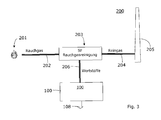
- Fig. 3 are further steps of a first invention Process, respectively a part of a Silicon-Fire plant 200 shown.
- the carbon dioxide 101 from a combustion process 201 symbolized here by a fire
- an oxidation process by means of CO 2 capture eg with a Silicon-Fire flue gas cleaning system 203 taken.
- the silicone-fire flue gas cleaning system 203 can be constructed, for example, according to the principle of flue gas scrubbing, whereby the CO 2 is "washed out" of the flue gas 202 by a scrubbing solution.
- a flue gas scrubbing which uses NaOH as a washing solution and in which the NaOH is recycled. Details are for example the parallel application EP 1 958 683 taken on 7.8.2007. However, other principles of CO 2 capture or recovery can also be used.
- the silicone-fire flue gas cleaning system 203 makes it possible to remove CO 2 (referred to here as recyclable material) from the flue gas 202. This CO 2 is then fed directly or indirectly to the Silicon-Fire plant 100, which then generates / synthesizes a hydrocarbon (preferably methanol 108) using CO 2 as the carbon source and using electrical energy.
- CO 2 referred to here as recyclable material
- This CO 2 is then fed directly or indirectly to the Silicon-Fire plant 100, which then generates / synthesizes a hydrocarbon (preferably methanol 108) using CO 2 as the carbon source and using electrical energy.
- Fig. 4 shows in a schematic block diagram of the most important components / process steps of a silicon-fire system 100.
- This system 100 is designed so that a method for providing storable and transportable energy carriers 108 can be performed.
- the corresponding procedure is based on the following basic steps.
- Carbon dioxide 101 is provided as a carbon source, as previously described.
- the required electrical DC energy E1 is generated here as far as possible by means of renewable energy technology and the Silicon-Fire plant 100 made available.
- Particularly suitable as renewable energy technology are solar thermal systems 300 and photovoltaic systems 400, which are based on solar modules. It is also possible to provide a combination of both system types 300 and 400, since the area requirement, based on the electrical power, of the solar thermal system 300 is smaller than that of a Photovoltaic system 400.
- Fig. 4 is a particularly preferred system 100 shown, which is constructed so that it reduces or compensates for the aforementioned disadvantages. For this reason, an economically and ecologically optimal combination of regenerative power supply (by the systems 300 and / or 400) and conventional power supply, here represented by a part of a network 500, is preferably realized in the case of the inventive silicon-fire system 100.
- the silicone fire system 100 therefore provides in a preferred embodiment, the regenerative electrical energy E1 largely directly according to their attack for chemical reactions (here the electrolysis reaction 105) to use and thus also to save. Another portion of the required energy is obtained from the interconnected network 500. This Proportion is converted into direct current (energy) E2.
- a corresponding converter 501 is used, as in Fig. 4 indicated in schematic form.
- the corresponding system components or components are also referred to here as power supply system 501.
- each of the currently available excess energy components E2 is taken from the interconnected network 500, while the other energy component (here E1) is sourced as far as possible from a plant-related solar power plant 300 and / or 400 (or from a wind power plant) an intelligent reversal of the previous principle, in which the energy fluctuations of renewable energy systems 300, 400 are intercepted by switching on and off conventional systems.
- E1 the energy component
- a Silicon-Fire system 100 no additional power and frequency control capacities are required for the regenerative power plants in the interconnected network 500
- This principle allows the operator of a Silicon-Fire plant 100 to include additional technical and economic parameters in the control of the plant 100.
- parameters are so-called input quantities I1, 12, etc., which are provided by the controller 110 included in decisions
- a part of the parameters can be specified within the controller 110 in a parameter memory 111.
- Another part of the parameters can come from the outside.
- price and / or availability information can be received from the operator of the interconnected network 500.
- a processor of the controller 110 executes control software and makes decisions taking parameters into account. These decisions are implemented in switching or control commands that cause, for example, via control or signal lines 112, 113, 114, the control of energy and mass flows.
- the Silicon-Fire system 100 is a consumer that can quickly turn on and off can be switched off and is relatively flexible. If, for example, there is a sudden increase in the demand for electrical energy on the network side, then the controller 110 can shut down or completely switch off the proportion E2. In this case either less hydrogen 103 is produced from this moment on, if energy E1 is available, or the electrolysis is temporarily stopped altogether.
- Fig. 4 is indicated by dashed arrows 112, which emanate from the controller 110 that the controller 110 controls the energy flows E1 and E2.
- the arrows 112 represent control or signal lines.
- Other possible control or signal lines 113, 114 are also shown.
- the control or signal line 113 controls, for example, the amount of CO 2 available for the reaction 106. For example, if less hydrogen is produced 103, since no energy E2 is available, then only less CO 2 must be supplied.
- the optional control or signal line 114 may regulate, for example, the amount of H 2 . Such a regulation is useful, for example, if there is a hydrogen buffer, which can be taken from hydrogen 103, even if at the moment no hydrogen or less hydrogen is produced by electrolysis 105.
- the Silicon-Fire plant 100 obtains between 15 and 50% of the electrical energy requirement solar and the remaining energy demand from the interconnected network 500 (i.e. mainly fossil). It is most preferred to cover between 30 and 40% of the electrical energy requirement solar and the remaining 70 to 60% from the interconnected network 500 (i.e., mainly fossil).
- the intelligent system controller 110 is set or programmed according to these specifications.
- the plant controller 110 is set or programmed so that the networking between regenerative electrical energy source 300 and / or 400 and interconnected electrical network 500 is optimized in such a way that the maximum cost of the electrical energy is minimized with maximum utilization of the regenerative electrical energy source 300 and / or 400.
- the plant controller 110 is set or programmed such that the networking between regenerative electrical energy source 300 and / or 400 and interconnected electrical network 500 is optimized such that with maximum utilization of the regenerative electrical energy source 300 and / or 400 and below Taking into account the total cost of electrical energy and the load or operating times of the entire system 100 and their equipment parts, the total cost of the hydrocarbon product 108 will be minimal.
- the plant controller 110 is set or programmed so that the networking between regenerative electrical energy source 300 and / or 400 and electrical interconnected network 500 is optimized in that by temporarily feeding the regenerative energy source 300 and / or 400 in the electrical Network 500 can be achieved at its peak times and thereby the total cost of electrical energy for the inventive method or the total cost of the hydrocarbon product 108 are reduced and minimized as possible.
- the renewable energy E1 - to achieve higher revenues - are also fed into the grid.
- controller 110 The aspects of these preferred embodiments can be readily combined by appropriate design of controller 110.
- silicon 603 as a first storable and transportable energy source
- methanol 108 as a second storable and transportable energy source.
- the method comprises at least the following steps.
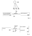
- silicon dioxide-containing raw material 601 is converted to elemental silicon 603 by a reduction process 602, as in FIG Fig. 5 shown.
- the elemental silicon 603 is referred to here for simplicity as silicon.
- the required electrical (primary) energy E1 for this reduction process 602 is provided according to the invention from a renewable energy source 300.
- a downstream step at least a portion of the silicon 603 may be employed in a methanol production process. In this process, for example, synthesis gas of carbon dioxide 101 and hydrogen 103 is used for methanol production.
- the silicon 603 can also be taken as an energy source from the process.
- the silicon 603 may be stored or removed, for example.
- the transformation 602 is preferably an electrochemical electrolytic transformation (involving electric current E1) as in Fig. 5 indicated schematically.
- the (primary) energy E1 for transformation is supplied by electricity generated from sunlight.
- a solar system 300 is used, as in Fig. 5 indicated schematically.
- significantly lower temperatures preferably less than 500 ° C. are required in electrochemical transformation 602.
- the reduced silicon 603 is a high energy substance. This silicon has the tendency to re-oxidize with water in liquid or vapor form to silica 604 (reverse reaction), as in Fig. 6 shown schematically.
- energy E3 eg heat energy
- hydrogen 1038 is produced, which can be used, for example, as an energy carrier for the production of methanol 108.
- hydrolysis 605 occurs at elevated temperatures. Preference is given to temperatures which are significantly above 100 ° C.
- the hydrolysis can also be carried out with aqueous hydroxide and alkali carbonate solutions, preferably temperatures between 60 and 150 ° C come into question.
- the silicon 603 is introduced into a reaction zone and mixed with water 102 in liquid or vapor form.
- the silicon 603 has a minimum temperature.
- the silicon 603 is heated for this purpose (eg with heating means, or by heat-generating or heat-emitting additives), or the silicon 603 is already at the introduction at a corresponding temperature level.
- the methanol production can be carried out according to one of the known and industrially used methods. Preference is given to a process in which a catalyst (for example a CuO-ZnO-Cr 2 O 3 or a Cu-Zn-Al 2 O 3 catalyst) is used.
- a catalyst for example a CuO-ZnO-Cr 2 O 3 or a Cu-Zn-Al 2 O 3 catalyst
- the invention has the advantage that in the reduction of the silicon dioxide and in the reduction of the water 102 no CO 2 is released, as long as only energy E1 is used for these reactions, which comes from a plant 300 and / or 400.
- the required energy is therefore at least partly from renewable energy sources, preferably from Annexes 300 and / or 400.
- the elemental silicon 603 is preferably used in powder form, or in granular or granular form in the hydrolysis 605.
- CO 2 101 serves as the starting material and carbon source for the synthesis of methanol in the reactor 106.
- the CO 2 source used are preferably: steam reforming plants, natural gas CO 2 separation plants, cement factories, bioethanol plants, seawater desalination plants, power plants and other plants or combustion processes 201 that emit large amounts of CO 2 .
- the invention makes it possible to avoid the considerable economic disadvantages of known approaches, if - as in the case of the Silicon-Fire plant 100 - the transiently occurring electric solar and / or wind energy is directly converted into chemical reaction enthalpy and stored chemically bound without additional Capacities for reserve power and / or frequency regulation in the interconnected network and the necessary expenses are necessary.
- a further advantage is that the direct current E1 primarily arising from the solar cells of the photovoltaic system 400 can be used directly for the chemical process (electrolysis 105) without having to be converted into alternating current for voltage transformation via converters.
Priority Applications (1)
| Application Number | Priority Date | Filing Date | Title |
|---|---|---|---|
| EP13175400.4A EP2647596A3 (fr) | 2008-12-18 | 2009-08-13 | Procédé et appareil pour fournir une source d'énergie en utilisant du dioxyde de carbone comme source de carbone et de l'énergie électrique |
Applications Claiming Priority (4)
| Application Number | Priority Date | Filing Date | Title |
|---|---|---|---|
| PCT/EP2008/067895 WO2010069385A1 (fr) | 2008-12-18 | 2008-12-18 | Procédé de préparation d'un vecteur d'énergie |
| EP09154271 | 2009-03-04 | ||
| EP09781782A EP2367753A1 (fr) | 2008-12-18 | 2009-08-13 | Procédé et installation permettant de produire une source d énergie en utilisant du dioxyde de carbone comme source de carbone et en utilisant l énergie électrique |
| EP13175400.4A EP2647596A3 (fr) | 2008-12-18 | 2009-08-13 | Procédé et appareil pour fournir une source d'énergie en utilisant du dioxyde de carbone comme source de carbone et de l'énergie électrique |
Related Parent Applications (2)
| Application Number | Title | Priority Date | Filing Date |
|---|---|---|---|
| EP09781782.9 Division | 2009-08-13 | ||
| EP09781782A Division EP2367753A1 (fr) | 2008-12-18 | 2009-08-13 | Procédé et installation permettant de produire une source d énergie en utilisant du dioxyde de carbone comme source de carbone et en utilisant l énergie électrique |
Publications (2)
| Publication Number | Publication Date |
|---|---|
| EP2647596A2 true EP2647596A2 (fr) | 2013-10-09 |
| EP2647596A3 EP2647596A3 (fr) | 2014-08-27 |
Family
ID=41077111
Family Applications (2)
| Application Number | Title | Priority Date | Filing Date |
|---|---|---|---|
| EP09781782A Withdrawn EP2367753A1 (fr) | 2008-12-18 | 2009-08-13 | Procédé et installation permettant de produire une source d énergie en utilisant du dioxyde de carbone comme source de carbone et en utilisant l énergie électrique |
| EP13175400.4A Withdrawn EP2647596A3 (fr) | 2008-12-18 | 2009-08-13 | Procédé et appareil pour fournir une source d'énergie en utilisant du dioxyde de carbone comme source de carbone et de l'énergie électrique |
Family Applications Before (1)
| Application Number | Title | Priority Date | Filing Date |
|---|---|---|---|
| EP09781782A Withdrawn EP2367753A1 (fr) | 2008-12-18 | 2009-08-13 | Procédé et installation permettant de produire une source d énergie en utilisant du dioxyde de carbone comme source de carbone et en utilisant l énergie électrique |
Country Status (5)
| Country | Link |
|---|---|
| US (1) | US9631287B2 (fr) |
| EP (2) | EP2367753A1 (fr) |
| CA (1) | CA2747097C (fr) |
| DE (1) | DE202009019105U1 (fr) |
| WO (1) | WO2010069622A1 (fr) |
Cited By (1)
| Publication number | Priority date | Publication date | Assignee | Title |
|---|---|---|---|---|
| DE102014016894A1 (de) * | 2014-11-17 | 2016-05-19 | Gensoric Gmbh | Verfahren und Vorrichtung zur Umwandlung gasförmiger Kohlenstoffverbindungen |
Families Citing this family (23)
| Publication number | Priority date | Publication date | Assignee | Title |
|---|---|---|---|---|
| US9631287B2 (en) | 2008-12-18 | 2017-04-25 | Silicon Fire Ag | Method and facility system for providing an energy carrier by application of carbon dioxide as a carbon supplier of electric energy |
| DE202010012734U1 (de) | 2010-09-03 | 2011-12-05 | Carbon-Clean Technologies Ag | Energieträger-Erzeugungsanlage zum kohlendioxidneutralen Ausgleich von Erzeugungsspitzen und Erzeugungstälern bei der Erzeugung von elektrischer Energie und/oder zur Erzeugung eines kohlenwasserstoffhaltigen Energieträgers |
| ES2402398T3 (es) * | 2010-09-03 | 2013-05-03 | Carbon-Clean Technologies Ag | Procedimiento e instalación de generación de portador de energía para la compensación neutra en dióxido de carbono de picos de generación y valles de generación en la generación de energía eléctrica y/o para la generación de un portador de energía que contiene hidrocarburo |
| EP2624947B1 (fr) | 2010-10-06 | 2016-04-27 | Silicon Fire AG | Procédé et installation de synthèse d'hydrocarbure |
| EP2438980A1 (fr) * | 2010-10-06 | 2012-04-11 | Silicon Fire AG | Procédé et dispositif de préparation et d'installation de méthanol à base d'hydrogène à des fins de dénitrification |
| EP2438982A1 (fr) | 2010-10-06 | 2012-04-11 | Silicon Fire AG | Procédé de préparation et d'utilisation d'un alcool et utilisation de l'alcool pour l'augmentation du degré d'action et de la puissance d'un moteur à combustion interne |
| EP2758317B1 (fr) | 2011-09-21 | 2018-06-27 | Silicon Fire AG | Dispositif de réception, de stockage, de transport et de distribution d'un liquide, ainsi que système global et véhicule muni d'un tel système global |
| EP2650401A1 (fr) * | 2012-04-10 | 2013-10-16 | Siemens Aktiengesellschaft | Système de méthanation basée sur une centrale électrique |
| DE102012025722B3 (de) | 2012-04-24 | 2018-08-23 | Karl Werner Dietrich | Verfahren zur Verbrennung von Erdgas/Methan |
| CN104919023B (zh) | 2013-01-04 | 2016-08-24 | 沙特阿拉伯石油公司 | 利用太阳辐射通过合成气制备单元将二氧化碳转化为烃类燃料 |
| EP3017167A1 (fr) | 2013-04-11 | 2016-05-11 | Silicon Fire AG | Procede et dispositif de réglage de puissance d'un moteur à combustion interne |
| EP3016924A1 (fr) | 2013-04-26 | 2016-05-11 | Silicon Fire AG | Procédé et système de réacteur de synthèse de méthanol avec recyclage du gaz circulant et du gaz de purge |
| EP2806115A1 (fr) * | 2013-05-23 | 2014-11-26 | Ivan Raisz | Batterie a haute performance utilisant dioxyde de carbone |
| EP3019582B1 (fr) * | 2013-07-09 | 2017-09-06 | Mitsubishi Hitachi Power Systems Europe GmbH | Centrale à fonctionnement flexible et son procédé d'exploitation |
| EP2876150A1 (fr) * | 2013-11-21 | 2015-05-27 | RV Lizenz AG | Réseau d'énergie combiné |
| DE102013020511A1 (de) * | 2013-12-11 | 2015-06-11 | Karl Werner Dietrich | Speicherkraftwerk Brennstoffzelle |
| WO2016189031A1 (fr) * | 2015-05-25 | 2016-12-01 | Gas2Green | Traitement électrolytique d'eau de lavage d'épurateur |
| DE102016208938A1 (de) | 2015-10-16 | 2017-04-20 | Volkswagen Aktiengesellschaft | Verfahren und Anlage zur Erzeugung eines Kohlenwasserstoffs |
| EP3156519B1 (fr) | 2015-10-16 | 2018-08-29 | Volkswagen Aktiengesellschaft | Procédé et appareil de production d'un hydrocarbure |
| DE102018105643B3 (de) | 2018-03-12 | 2019-05-16 | Edgar Harzfeld | Verfahren zur unterbrechungsfreien Stromversorgung mittels einer Schnellbereitschaftsanlage sowie Schnellbereitschaftsanlage |
| WO2019228809A1 (fr) * | 2018-05-30 | 2019-12-05 | Siemens Aktiengesellschaft | Centrale électrique comprenant un électrolysuer et synthèse de combustible |
| CN112886621A (zh) * | 2021-03-09 | 2021-06-01 | 上海交通大学 | 一种可再生电能储能系统 |
| DE202023100827U1 (de) | 2023-02-22 | 2023-07-10 | Edgar Harzfeld | Schnellbereitschaftsanlage zur unterbrechungsfreien Stromversorgung einer Elektrotankstelle mit beliebig vielen Ladesäulen |
Citations (8)
| Publication number | Priority date | Publication date | Assignee | Title |
|---|---|---|---|---|
| DE4332789A1 (de) * | 1993-09-27 | 1995-03-30 | Abb Research Ltd | Verfahren zur Speicherung von Energie |
| US20020025457A1 (en) * | 1998-10-27 | 2002-02-28 | Dodd Peter Jeremy | Electrical energy storage |
| US20020033332A1 (en) * | 2000-09-14 | 2002-03-21 | Kiyoshi Handa | Water Electrolytic system |
| US20040063052A1 (en) * | 2000-09-29 | 2004-04-01 | Peter Plichta | Novel concept for generating power via an inorganic nitrogen cycle, based on sand as the starting material and producing higher silanes |
| DE102006034712A1 (de) * | 2006-07-27 | 2008-01-31 | Steag Saar Energie Ag | Verfahren zur Reduzierung der CO2-Emission fossil befeuerter Kraftwerksanlagen |
| DE102006035893A1 (de) * | 2006-07-31 | 2008-02-07 | Wolf, Bodo M., Dr. | Verfahren zur Wiederaufarbeitung von Verbrennungsprodukten fossiler Brennstoffe |
| EP1887071A1 (fr) * | 2006-07-31 | 2008-02-13 | Edmund Dr.-Ing. Wagner | Procédé de production d'hydrocarbures synthétiques et leurs dérivés à partir de dioxide de carbone et de dihydrogène utilisés comme gaz de synthèse |
| US20080283411A1 (en) * | 2007-05-04 | 2008-11-20 | Eastman Craig D | Methods and devices for the production of Hydrocarbons from Carbon and Hydrogen sources |
Family Cites Families (15)
| Publication number | Priority date | Publication date | Assignee | Title |
|---|---|---|---|---|
| US3215522A (en) | 1960-11-22 | 1965-11-02 | Union Carbide Corp | Silicon metal production |
| DE2924584A1 (de) | 1979-06-19 | 1981-01-15 | Straemke Siegfried | Verfahren zur herstellung von silicium fuer solarzellen |
| US4457902A (en) | 1980-10-24 | 1984-07-03 | Watson Keith R | High efficiency hydrocarbon reduction of silica |
| US4897852A (en) | 1988-08-31 | 1990-01-30 | Dow Corning Corporation | Silicon smelting process |
| NO310142B1 (no) | 1999-03-29 | 2001-05-28 | Elkem Materials | Fremgangsmåte for fremstilling av amorft silica fra silisium og fra silisiumholdige materialer |
| WO2002090257A1 (fr) | 2001-05-03 | 2002-11-14 | Wacker-Chemie Gmbh | Procede de production d'energie |
| US6540902B1 (en) | 2001-09-05 | 2003-04-01 | The United States Of America As Represented By The United States Department Of Energy | Direct electrochemical reduction of metal-oxides |
| DE10258072A1 (de) | 2002-12-11 | 2004-07-01 | Wacker-Chemie Gmbh | Verfahren zur Erzeugung von Wasserstoff |
| GB0422129D0 (en) | 2004-10-06 | 2004-11-03 | Qinetiq Ltd | Electro-reduction process |
| GB0504444D0 (en) | 2005-03-03 | 2005-04-06 | Univ Cambridge Tech | Method and apparatus for removing oxygen from a solid compound or metal |
| EP1991500A2 (fr) | 2006-02-20 | 2008-11-19 | Hyattville Company Ltd. | Préparation de silicium de qualité solaire et éléctronique à partir de matériaux contenant des aluminosilicates |
| EP1918248A3 (fr) | 2006-10-29 | 2010-06-09 | Silicon Fire AG | Préparation d'H2O2 à partir d'acide sulfurique, obtenu par combustion de matières combustibles fossiles contenant de résidus de soufre, et utilisation de H2O2 en tant que source d'énergie |
| EP1958683A3 (fr) | 2007-01-11 | 2010-08-25 | Silicon Fire AG | Procédé destiné au traitement de gaz de fumée pour centrales et autres installations |
| US9631287B2 (en) | 2008-12-18 | 2017-04-25 | Silicon Fire Ag | Method and facility system for providing an energy carrier by application of carbon dioxide as a carbon supplier of electric energy |
| CA2747083A1 (fr) | 2008-12-18 | 2010-06-24 | Silicon Fire Ag | Procede de preparation d'un vecteur d'energie |
-
2009
- 2009-08-13 US US13/140,826 patent/US9631287B2/en active Active
- 2009-08-13 WO PCT/EP2009/060472 patent/WO2010069622A1/fr active Application Filing
- 2009-08-13 EP EP09781782A patent/EP2367753A1/fr not_active Withdrawn
- 2009-08-13 DE DE202009019105.2U patent/DE202009019105U1/de not_active Expired - Lifetime
- 2009-08-13 CA CA2747097A patent/CA2747097C/fr not_active Expired - Fee Related
- 2009-08-13 EP EP13175400.4A patent/EP2647596A3/fr not_active Withdrawn
Patent Citations (8)
| Publication number | Priority date | Publication date | Assignee | Title |
|---|---|---|---|---|
| DE4332789A1 (de) * | 1993-09-27 | 1995-03-30 | Abb Research Ltd | Verfahren zur Speicherung von Energie |
| US20020025457A1 (en) * | 1998-10-27 | 2002-02-28 | Dodd Peter Jeremy | Electrical energy storage |
| US20020033332A1 (en) * | 2000-09-14 | 2002-03-21 | Kiyoshi Handa | Water Electrolytic system |
| US20040063052A1 (en) * | 2000-09-29 | 2004-04-01 | Peter Plichta | Novel concept for generating power via an inorganic nitrogen cycle, based on sand as the starting material and producing higher silanes |
| DE102006034712A1 (de) * | 2006-07-27 | 2008-01-31 | Steag Saar Energie Ag | Verfahren zur Reduzierung der CO2-Emission fossil befeuerter Kraftwerksanlagen |
| DE102006035893A1 (de) * | 2006-07-31 | 2008-02-07 | Wolf, Bodo M., Dr. | Verfahren zur Wiederaufarbeitung von Verbrennungsprodukten fossiler Brennstoffe |
| EP1887071A1 (fr) * | 2006-07-31 | 2008-02-13 | Edmund Dr.-Ing. Wagner | Procédé de production d'hydrocarbures synthétiques et leurs dérivés à partir de dioxide de carbone et de dihydrogène utilisés comme gaz de synthèse |
| US20080283411A1 (en) * | 2007-05-04 | 2008-11-20 | Eastman Craig D | Methods and devices for the production of Hydrocarbons from Carbon and Hydrogen sources |
Cited By (2)
| Publication number | Priority date | Publication date | Assignee | Title |
|---|---|---|---|---|
| DE102014016894A1 (de) * | 2014-11-17 | 2016-05-19 | Gensoric Gmbh | Verfahren und Vorrichtung zur Umwandlung gasförmiger Kohlenstoffverbindungen |
| EP3221458A2 (fr) * | 2014-11-17 | 2017-09-27 | Gensoric GmbH | Procédé et dispositif pour la procuction de composés carboniques |
Also Published As
| Publication number | Publication date |
|---|---|
| CA2747097C (fr) | 2017-05-23 |
| EP2647596A3 (fr) | 2014-08-27 |
| CA2747097A1 (fr) | 2010-06-24 |
| US20120010305A1 (en) | 2012-01-12 |
| WO2010069622A1 (fr) | 2010-06-24 |
| US9631287B2 (en) | 2017-04-25 |
| EP2367753A1 (fr) | 2011-09-28 |
| DE202009019105U1 (de) | 2016-07-14 |
Similar Documents
| Publication | Publication Date | Title |
|---|---|---|
| EP2647596A2 (fr) | Procédé et appareil pour fournir une source d'énergie en utilisant du dioxyde de carbone comme source de carbone et de l'énergie électrique | |
| EP2464617B1 (fr) | Procédé et installation de production d'une ressource énergétique à base d'hydrocarbure en utilisant une fraction de méthanol produit par régénération et une fraction de méthanol qui est produit par oxydation directe ou par oxydation partielle ou par reformage | |
| EP3019582B1 (fr) | Centrale à fonctionnement flexible et son procédé d'exploitation | |
| EP2426236B1 (fr) | Procédé et installation de production de support d'énergie pour l'équilibrage neutre en dioxyde de carbone de pointes de production et de creux de production lors de la production d'énergie électrique et/ou pour la production d'un support d'énergie contenant de l'hydrocarbure | |
| EP2100869B1 (fr) | Procédé de fabrication de méthanol en utilisant du dioxyde de carbone à partir de gaz d'échappement d'installations de production d'énergie à fonctionnement fossile | |
| DE102012103458B4 (de) | Anlage und Verfahren zur ökologischen Erzeugung und Speicherung von Strom | |
| WO2015044407A1 (fr) | Procédé et système de stockage d'énergie électrique | |
| WO2011101209A2 (fr) | Procédé et dispositif de valorisation d'émissions d'une centrale électrique | |
| EP3156519B1 (fr) | Procédé et appareil de production d'un hydrocarbure | |
| DE102015005940A1 (de) | Verfahren zur verbesserten Integration regenerativer Energiequellen in das existierende Energiesystem durch Umwandlung elektrischer Energie in chemische Energie mit Zwischenspeicherung des verflüssigten CO, wodurch eine Reduzierung der CO2 Emission erziel | |
| EP2682450B1 (fr) | Procédé de méthanisation catalytique et installation de méthanisation | |
| EP2624947A1 (fr) | Procédé et installation de synthèse d'hydrocarbure | |
| EP2367752A1 (fr) | Silicium ou métaux élémentaires comme sources d'énergie | |
| EP1918248A2 (fr) | Préparation d'H2O2 à partir d'acide sulfurique, obtenu par combustion de matières combustibles fossiles contenant de résidus de soufre, et utilisation de H2O2 en tant que source d'énergie | |
| EP2438980A1 (fr) | Procédé et dispositif de préparation et d'installation de méthanol à base d'hydrogène à des fins de dénitrification | |
| DE102015216037A1 (de) | Verfahren zur Bereitstellung eines Synthesegases | |
| DE102021122602B4 (de) | Anlage und Verfahren zur kontinuierlichen Herstellung von Ammoniak unter Verwendung von erneuerbaren Energien | |
| EP3686154A1 (fr) | Procédé de fonctionnement d'une installation de synthèse d'un produit chimique | |
| LU103015B1 (de) | Anlage und Verfahren zur Erzeugung von grünem Harnstoff | |
| DE102013211685B4 (de) | Kombiniertes Verfahren zur Nutzung von Roh-Biogas enthaltend Kohlendioxid und ein Nutzgas | |
| DE102016208938A1 (de) | Verfahren und Anlage zur Erzeugung eines Kohlenwasserstoffs | |
| DE102015017254B3 (de) | Verfahren zur Integration regenerativ erzeugten Stroms unter Nutzung von Kohlenmonoxid | |
| WO2024062060A1 (fr) | Système et procédé de production d'urée verte | |
| EP3722462A1 (fr) | Installation et procédé d'accumulation d'énergie électrique | |
| EP3314042B1 (fr) | Production d'énergie par des procédés de biosynthèse |
Legal Events
| Date | Code | Title | Description |
|---|---|---|---|
| PUAI | Public reference made under article 153(3) epc to a published international application that has entered the european phase |
Free format text: ORIGINAL CODE: 0009012 |
|
| AC | Divisional application: reference to earlier application |
Ref document number: 2367753 Country of ref document: EP Kind code of ref document: P |
|
| AK | Designated contracting states |
Kind code of ref document: A2 Designated state(s): AT BE BG CH CY CZ DE DK EE ES FI FR GB GR HR HU IE IS IT LI LT LU LV MC MK MT NL NO PL PT RO SE SI SK SM TR |
|
| RIC1 | Information provided on ipc code assigned before grant |
Ipc: C01B 3/06 20060101AFI20140403BHEP Ipc: C25B 15/00 20060101ALI20140403BHEP Ipc: C01B 33/12 20060101ALI20140403BHEP Ipc: C25B 1/04 20060101ALI20140403BHEP Ipc: C10G 2/00 20060101ALI20140403BHEP Ipc: C01B 33/023 20060101ALI20140403BHEP |
|
| PUAL | Search report despatched |
Free format text: ORIGINAL CODE: 0009013 |
|
| AK | Designated contracting states |
Kind code of ref document: A3 Designated state(s): AT BE BG CH CY CZ DE DK EE ES FI FR GB GR HR HU IE IS IT LI LT LU LV MC MK MT NL NO PL PT RO SE SI SK SM TR |
|
| RIC1 | Information provided on ipc code assigned before grant |
Ipc: C01B 33/12 20060101ALI20140723BHEP Ipc: C25B 1/04 20060101ALI20140723BHEP Ipc: C01B 33/023 20060101ALI20140723BHEP Ipc: C10G 2/00 20060101ALI20140723BHEP Ipc: C01B 3/06 20060101AFI20140723BHEP Ipc: C25B 15/00 20060101ALI20140723BHEP |
|
| 17P | Request for examination filed |
Effective date: 20150227 |
|
| RBV | Designated contracting states (corrected) |
Designated state(s): AT BE BG CH CY CZ DE DK EE ES FI FR GB GR HR HU IE IS IT LI LT LU LV MC MK MT NL NO PL PT RO SE SI SK SM TR |
|
| STAA | Information on the status of an ep patent application or granted ep patent |
Free format text: STATUS: THE APPLICATION IS DEEMED TO BE WITHDRAWN |
|
| 18D | Application deemed to be withdrawn |
Effective date: 20160301 |