EP2647552A1 - Hood inner panel - Google Patents
Hood inner panel Download PDFInfo
- Publication number
- EP2647552A1 EP2647552A1 EP11845779.5A EP11845779A EP2647552A1 EP 2647552 A1 EP2647552 A1 EP 2647552A1 EP 11845779 A EP11845779 A EP 11845779A EP 2647552 A1 EP2647552 A1 EP 2647552A1
- Authority
- EP
- European Patent Office
- Prior art keywords
- bead
- vehicle
- hood
- width direction
- inner panel
- Prior art date
- Legal status (The legal status is an assumption and is not a legal conclusion. Google has not performed a legal analysis and makes no representation as to the accuracy of the status listed.)
- Granted
Links
Images


Classifications
-
- B—PERFORMING OPERATIONS; TRANSPORTING
- B62—LAND VEHICLES FOR TRAVELLING OTHERWISE THAN ON RAILS
- B62D—MOTOR VEHICLES; TRAILERS
- B62D25/00—Superstructure or monocoque structure sub-units; Parts or details thereof not otherwise provided for
- B62D25/08—Front or rear portions
- B62D25/10—Bonnets or lids, e.g. for trucks, tractors, busses, work vehicles
- B62D25/105—Bonnets or lids, e.g. for trucks, tractors, busses, work vehicles for motor cars
-
- B—PERFORMING OPERATIONS; TRANSPORTING
- B60—VEHICLES IN GENERAL
- B60R—VEHICLES, VEHICLE FITTINGS, OR VEHICLE PARTS, NOT OTHERWISE PROVIDED FOR
- B60R21/00—Arrangements or fittings on vehicles for protecting or preventing injuries to occupants or pedestrians in case of accidents or other traffic risks
- B60R21/34—Protecting non-occupants of a vehicle, e.g. pedestrians
- B60R2021/343—Protecting non-occupants of a vehicle, e.g. pedestrians using deformable body panel, bodywork or components
Definitions
- the present invention relates to a hood inner panel forming part of a hood of a vehicle.
- Patent Document 1 describes an inner panel of a hood for a vehicle provided with a plurality of beads extending in a vehicle width direction to enhance an energy absorption capacity at the time of impact.
- the hood described above is required to have a high initial reaction force against the impact exerted on the hood in order to enhance the energy absorption capacity.
- the hood is further required to minimize a reduction of a reaction force by deformation in collision.
- a hood inner panel includes an inner panel main body forming part of a hood of a vehicle, a front bead provided on the inner panel main body and extending along a vehicle width direction, and a rear bead provided on the inner panel main body, located on a rear side of the front bead and extending along the vehicle width direction.
- the front bead includes a center portion in the vehicle width direction that is curved toward a front of the vehicle and located in front of each end portion in the vehicle width direction
- the rear bead includes a center portion in the vehicle width direction that is curved toward a back of the vehicle and located behind each end portion in the vehicle width direction.
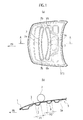
- a hood 1 for a vehicle includes a hood outer panel 3 located on the outer side of a vehicle body, and a hood inner panel 5 fixed to the inner surface of the hood outer panel 3 inside the vehicle body.
- the hood inner panel 5 includes an inner panel main body 5a provided with a front bead 7 and a rear bead 9 extending in a vehicle width direction.
- Each center in the vehicle width direction of the front bead 7 and the rear bead 9 is substantially coincident with the center in the vehicle width direction of the hood inner panel 5 (the hood 1).
- the direction indicated by the arrow FR in FIG. 1 is the front side of the vehicle, and the vertical direction in FIG 1 (a) is the vehicle width direction.
- the front bead 7 and the rear bead 9 are projections projecting to the inside of the vehicle in the direction away from the hood outer panel 3.
- the front bead 7 is provided on the hood inner panel 5 toward the front of the vehicle.
- the front bead 7 includes a center portion 7a that is curved toward the front of the vehicle and located in front of end portions 7b on both sides in the vehicle width direction.
- the front bead 7 projects to the inside of the vehicle, and the projection is tapered toward the tip.
- the projection has a width H1 at the base portion, which is defined as a width of the front bead 7.
- the width H1 of the front bead 7 in the front-back direction of the vehicle is gradually increased from the center portion 7a toward the end portions 7b on both sides in the vehicle width direction.
- the rear bead 9 is located on the rear side of the front bead 7.
- the rear bead 9 includes a center portion 9a that is curved toward the back of the vehicle and located behind end portions 9b on both sides in the vehicle width direction.
- the rear bead 9 also has a width H2 in the front-back direction of the vehicle that is gradually increased from the center portion 9a toward the end portions 9b on both sides in the vehicle width direction.
- the width H2 at the base portion of the projection is defined as a width of the rear bead 9 in the front-back direction as in the case of the front bead 7.
- the center portion 7a of the front bead 7 is curved toward the front of the vehicle, while the center portion 9a of the rear bead 9 is curved toward the back of the vehicle. Namely, the respective front and rear beads 7 and 9 are curved in opposite directions.
- the gap between the center portion 7a of the front bead 7 and the center portion 9a of the rear bead 9 is larger than the gap between each end portion 7b of the front bead 7 and each end portion 9b of the rear bead 9.
- An impact load applied to the hood inner panel 5 is gradually transmitted in directions from the center portions 7a and 9a toward the respective end portions 7b and 9b on both sides in the front and rear beads 7 and 9 as indicated by the arrows E in FIG 2(a) .
- the respective front and rear beads 5 and 9 are curved in opposite directions. Therefore, as shown in FIG. 2(b) , moments M1 and M2 caused in the center portions 7a and 9a around the cross-section of each projection are transmitted in opposite directions.
- the moments M1 and M2 caused in the center portions 7a and 9a are gradually transmitted to both sides in the vehicle width direction as shown in FIG 2(b) .
- the moments M1 and M2 reach the respective end portions 7b and 9b on both sides in the vehicle width direction and finally change to moments M3 and M4 shown in FIG. 2(c) .
- the moments M1 and M2 in opposite directions are caused around the cross-section of each projection of the respective front and rear beads 7 and 9, and are finally transmitted to the respective end portions 7b and 9b on both sides in the vehicle width direction.
- the front bead 7 and the rear bead 9 are curved to come closer to each other from the respective center portions 7a and 9a toward the respective end portions 7b and 9b on both sides. Therefore, the moments M1 and M2 around the cross-section of each projection shown in FIG. 2(b) are likely to be mutually offset gradually toward the respective end portions 7b and 9b on both sides in the vehicle width direction, and a level of vertical deformation caused by the impact load can be minimized. As a result, deformation in the vertical direction of the vehicle in the respective end portions 7b and 9b on both sides of the respective front and rear beads 7 and 9 can be prevented. In addition, deformation in the vertical direction in the center portions 7a and 9a can also be prevented and accordingly, deformation in the vertical direction in the entire hood 1 can be prevented.
- the gap between the hood 1 and contents located in the engine (motor) room below the hood 1 can be minimized. Therefore, it is possible to expand the possibility of design of the vehicle body and the engine (motor) room.
- the impact load input by the collision reaches the end portion 7b on one side in the vehicle width direction from the center portion 7a of the front bead 7 as indicated by the arrow F.
- This input is likely to cause distortion in the region S between the end portion 7b on one side and the end portion 9b of the rear bead 9 on the same side and as a result, the entire hood 1 can be easily bent in the front-back direction of the vehicle. Accordingly, the level of deformation toward the outer surface can be minimized when the upper surface of the hood 1 is hit with the object P and at the same time, the impact absorption capacity can be improved due to the hood 1 that is easily bent by the head-on collision.
- FIG. 4 exemplifies the case of the head-on collision with the object Q on one side in the vehicle width direction at the offset position from the center of the vehicle, the similar effect can be ensured also in the case of the head-on collision with the object Q at the center portion in the vehicle width direction.
- the impact load input by the collision at the center portion reaches the respective end portions 7b and 9b on both sides in the vehicle width direction from the center portions 7a and 9a of the respective front and rear beads 7 and 9.
- distortion is caused in both areas between the respective end portions 7b and 9b on both sides in the vehicle width direction.
- At least one of the front bead 7 and the rear bead 9 increases in width in the front-back direction toward the end portions 7b or 9b on both sides from the front portion 7a or 9a.
- Such a configuration increases the rigidity of the end portions 7b and 9b on both sides more than the rigidity of the center portions 7a and 9a. Therefore, the level of deformation at the end portions 7b and 9b on both sides decreases and accordingly, deformation of the entire hood 1 can be minimized.
- the moments caused by the input of the impact load particularly turn the center portions 7a and 9a of the respective front and rear beads 7 and 9 on the end portions 7b and 9b on both sides serving as supporting points.
- such an input load can be effectively distributed in the hood 1 in the front-back direction of the vehicle.
- the front bead 7 is formed in such a way that the width H1 in the front-back direction of the vehicle is gradually increased from the center portion 7a toward the end portions 7b on both sides.
- the width H1 may be substantially the same along the vehicle width direction instead of being changed.
- the width H2 of the rear bead 9 in the front-back direction of the vehicle may be substantially the same along the vehicle width direction.
- a hood inner panel according to the second embodiment of the present invention is explained below with reference to the drawings. Note that the same components as in the first embodiment are indicated by the same reference numerals, and the explanations thereof are not repeated in this embodiment.
- an intermediate bead 11 is formed in an ellipsoidal shape extending in the vehicle width direction, and is provided between the front bead 7 and the rear bead 9 explained in the first embodiment.
- the intermediate bead 11 is located in the center of the hood inner panel 5 in the vehicle width direction.
- the center of the intermediate bead 11 in the vehicle width direction is substantially coincident with each center of the front bead 7 and the rear bead 9 in the vehicle width direction.
- the hood inner panel 5 has regions between the intermediate bead 11 and each of the front bead 7 and the rear bead 9 where the hood inner panel 5 is attached to the hood outer panel 3.
- the radius of curvature of the curved portion in the intermediate bead 11 on the front bead 7 side may be identical to, or may be different from the radius of curvature of the curved portion in the front bead 7 on the intermediate bead 11 side.
- the radius of curvature of the curved portion in the intermediate bead 11 on the rear bead 9 side may be identical to, or may be different from the radius of curvature of the curved portion in the rear bead 9 on the intermediate bead 11 side.
- the rigidity of the entire hood 1 can be increased due to the intermediate bead 11 provided between the front bead 7 and the rear bead 9.
- the front bead 7 and the rear bead 9 are deformed and pushed toward the front and the rear of the vehicle, respectively, due to the intermediate bead 11. Therefore, the energy absorption effect in the entire hood 1 can be further improved. Accordingly, the gap between the hood 1 and contents located in the engine (motor) room below the hood 1 can be further minimized.
- a hood inner panel according to the third embodiment of the present invention is explained below with reference to the drawings. Note that the same components as in the first embodiment and the second embodiment are indicated by the same reference numerals, and the explanations thereof are not repeated in this embodiment.
- the front bead 7 is curved to have a radius of curvature R1 on the front side thereof and the rear bead 9 is curved to have a radius of curvature R2 on the front side thereof, and the radius of curvature R2 is smaller than the radius of curvature R1 (R1>R2), compared with those in the second embodiment shown in FIG. 5 .
- the curved portion on the rear side of the front bead 7 has a radius of curvature R3 that is set in such a manner as to fulfill the condition of R1>R3.
- the curved portion on the rear side of the rear bead 9 has a radius of curvature R4 that is set in such a manner as to fulfill the condition of R4>R2.
- the radii of curvature of the respective curved portions in the front bead 7 and the rear bead 9 are set in such a manner as to fulfill the conditions of R1>R3 and R4>R2.
- the radii of curvature R1 to R4 are set in such a manner as to fulfill the conditions of R1>R4 and R3>R2.
- This configuration can ensure the same effects as in the first and the second embodiments. Further, the following effects can also be achieved in the present embodiment.
- each width in the front-back direction of the vehicle at the respective end portions 7b and 9b on both sides is greater than each width in the front-back direction of the vehicle at the respective center portions 7a and 9a in the respective front and rear beads 7 and 9, as in the case of the second embodiment shown in FIG. 1 .
- This structure can improve the rigidity at the end portions 7b and 9b on both sides since the end portions 7b and 9b on both sides have larger areas in cross-section than the center portions 7a and 9a.
- the input of the impact load that causes the moments which acts so as to particularly turn the center portions 7a and 9a of the respective front and rear beads 7 and 9 on the end portions 7b and 9b on both sides serving as supporting points can be effectively distributed in the hood 1 in the front-back direction of the vehicle.
- This effect can be ensured when at least one of the conditions of R1>R3 and R4>R2 is fulfilled.
- greater effects can be further achieved when the conditions of R1>R3 and R4>R2 are fulfilled concurrently.
- the present invention when the middle in the vehicle width direction of the front bead and the rear bead is hit with an object, moments in opposite directions are caused around the front bead and the rear bead curved in opposite directions, and the moments are then transmitted to the respective end portions on both sides in the vehicle width direction. Accordingly, even if a level of deformation of the hood increases, a reduction of the reaction force can be minimized and a sufficient energy absorption capacity can be ensured.
Landscapes
- Engineering & Computer Science (AREA)
- Mechanical Engineering (AREA)
- Chemical & Material Sciences (AREA)
- Combustion & Propulsion (AREA)
- Transportation (AREA)
- Superstructure Of Vehicle (AREA)
- Vehicle Interior And Exterior Ornaments, Soundproofing, And Insulation (AREA)
Abstract
Description
- The present invention relates to a hood inner panel forming part of a hood of a vehicle.
-
Patent Document 1 describes an inner panel of a hood for a vehicle provided with a plurality of beads extending in a vehicle width direction to enhance an energy absorption capacity at the time of impact. -
- Patent Document 1: Japanese Patent Unexamined Publication No.
2008-030574 - The hood described above is required to have a high initial reaction force against the impact exerted on the hood in order to enhance the energy absorption capacity. The hood is further required to minimize a reduction of a reaction force by deformation in collision.
- It is an object of the present invention to provide a hood inner panel capable of minimizing a reduction of a reaction force of the hood inner panel even if a level of deformation of a hood of a vehicle increases, and ensuring a sufficient energy absorption capacity.
- A hood inner panel according to the present invention includes an inner panel main body forming part of a hood of a vehicle, a front bead provided on the inner panel main body and extending along a vehicle width direction, and a rear bead provided on the inner panel main body, located on a rear side of the front bead and extending along the vehicle width direction. The front bead includes a center portion in the vehicle width direction that is curved toward a front of the vehicle and located in front of each end portion in the vehicle width direction, and the rear bead includes a center portion in the vehicle width direction that is curved toward a back of the vehicle and located behind each end portion in the vehicle width direction.
-
- [
FIG 1] FIG. 1(a) is a plan view of a hood inner panel of a hood for a vehicle according to a first embodiment of the present invention.FIG 1(b) is a cross-sectional view taken along the line A-A inFIG 1(a) . - [
FIG. 2] FIG. 2(a) to 2(c) are plan views explaining actions of impact by an object exerted on the upper surface of the hood inFIG 1(b) .FIG. 2(a) is a plan view showing directions in which impact loads are transmitted in beads.FIG 2(b) is a cross-sectional view showing moments caused in center portions in a vehicle width direction of the beads on the hood taken along the line B-B inFIG 2(a). FIG 2(c) a cross-sectional view showing moments caused in side portions in the vehicle width direction of the beads on the hood taken along the line C-C inFIG 2(a) - [
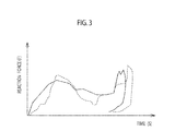
FIG. 3] FIG. 3 is an explanatory view showing a reaction force that varies with times after the impact by the object exerted on the upper surface of the hood. Note that the solid line inFIG. 3 represents the present embodiment, and the dashed line represents a conventional example in which beads extending in the vehicle width direction are not curved in contrast to the present embodiment. - [
FIG. 4] FIG 4 is an explanatory view showing a flow of the impact load transmitted in the bead at the time of frontal impact of the vehicle. - [
FIG 5] FIG 5(a) is a plan view of a hood inner panel of a hood for a vehicle according to a second embodiment of the present invention.FIG 5(b) is a cross-sectional view taken along the line D-D inFIG 5(a) . - [
FIG. 6] FIG. 6 is a plan view of a hood inner panel of a hood for a vehicle according to a third embodiment of the present invention. - Hereinafter, embodiments of the present invention will be explained in detail with reference to the drawings.
- As shown in
FIG 1 , ahood 1 for a vehicle includes a hoodouter panel 3 located on the outer side of a vehicle body, and a hoodinner panel 5 fixed to the inner surface of the hoodouter panel 3 inside the vehicle body. The hoodinner panel 5 includes an inner panelmain body 5a provided with afront bead 7 and arear bead 9 extending in a vehicle width direction. Each center in the vehicle width direction of thefront bead 7 and therear bead 9 is substantially coincident with the center in the vehicle width direction of the hood inner panel 5 (the hood 1). Note that the direction indicated by the arrow FR inFIG. 1 is the front side of the vehicle, and the vertical direction inFIG 1 (a) is the vehicle width direction. - As shown in
FIG. 1(b) , thefront bead 7 and therear bead 9 are projections projecting to the inside of the vehicle in the direction away from the hoodouter panel 3. - The
front bead 7 is provided on the hoodinner panel 5 toward the front of the vehicle. Thefront bead 7 includes acenter portion 7a that is curved toward the front of the vehicle and located in front ofend portions 7b on both sides in the vehicle width direction. The front bead 7 projects to the inside of the vehicle, and the projection is tapered toward the tip. As shown inFIG. 1(b) , the projection has a width H1 at the base portion, which is defined as a width of thefront bead 7. The width H1 of thefront bead 7 in the front-back direction of the vehicle is gradually increased from thecenter portion 7a toward theend portions 7b on both sides in the vehicle width direction. - The
rear bead 9 is located on the rear side of thefront bead 7. Therear bead 9 includes acenter portion 9a that is curved toward the back of the vehicle and located behindend portions 9b on both sides in the vehicle width direction. Therear bead 9 also has a width H2 in the front-back direction of the vehicle that is gradually increased from thecenter portion 9a toward theend portions 9b on both sides in the vehicle width direction. The width H2 at the base portion of the projection is defined as a width of therear bead 9 in the front-back direction as in the case of thefront bead 7. - As shown in
FIG. 1(a) , thecenter portion 7a of thefront bead 7 is curved toward the front of the vehicle, while thecenter portion 9a of therear bead 9 is curved toward the back of the vehicle. Namely, the respective front andrear beads center portion 7a of thefront bead 7 and thecenter portion 9a of therear bead 9 is larger than the gap between eachend portion 7b of thefront bead 7 and eachend portion 9b of therear bead 9. - The following is an explanation of a state in which the
hood 1 including the hoodinner panel 5 having the structure described above is hit, especially on the center portions of the front andrear beads inner panel 5, with an external object P as shown inFIG 1(b) . - An impact load applied to the hood
inner panel 5 is gradually transmitted in directions from thecenter portions respective end portions rear beads FIG 2(a) . In the present embodiment, the respective front andrear beads FIG. 2(b) , moments M1 and M2 caused in thecenter portions center portions FIG 2(b) . The moments M1 and M2 reach therespective end portions FIG. 2(c) . - In the present embodiment, when the respective front and
rear beads center portions rear beads respective end portions hood 1 increases, a high reaction force can be kept relatively for a long period of time, and a reduction of the reaction force can be minimized, so that a sufficient energy absorption capacity can be ensured. - In the present embodiment, the
front bead 7 and therear bead 9 are curved to come closer to each other from therespective center portions respective end portions FIG. 2(b) are likely to be mutually offset gradually toward therespective end portions respective end portions rear beads center portions entire hood 1 can be prevented. - Since deformation in the vertical direction of the vehicle in the
center portions FIG. 3 appears earlier than that in the conventional example indicated by the dashed line, and a peak reaction force can be kept longer than the conventional example. Therefore, the energy absorption property can be effectively exerted. - Due to the energy absorption effect, the gap between the
hood 1 and contents located in the engine (motor) room below thehood 1 can be minimized. Therefore, it is possible to expand the possibility of design of the vehicle body and the engine (motor) room. - As shown in
FIG. 4 , when the vehicle causes a head-on collision with an object Q, the impact load input by the collision reaches theend portion 7b on one side in the vehicle width direction from thecenter portion 7a of thefront bead 7 as indicated by the arrow F. This input is likely to cause distortion in the region S between theend portion 7b on one side and theend portion 9b of therear bead 9 on the same side and as a result, theentire hood 1 can be easily bent in the front-back direction of the vehicle. Accordingly, the level of deformation toward the outer surface can be minimized when the upper surface of thehood 1 is hit with the object P and at the same time, the impact absorption capacity can be improved due to thehood 1 that is easily bent by the head-on collision. - Although
FIG. 4 exemplifies the case of the head-on collision with the object Q on one side in the vehicle width direction at the offset position from the center of the vehicle, the similar effect can be ensured also in the case of the head-on collision with the object Q at the center portion in the vehicle width direction. The impact load input by the collision at the center portion reaches therespective end portions center portions rear beads respective end portions - In the present embodiment, at least one of the
front bead 7 and therear bead 9 increases in width in the front-back direction toward theend portions front portion end portions center portions end portions entire hood 1 can be minimized. - In particular, it is assumed that the moments caused by the input of the impact load particularly turn the
center portions rear beads end portions hood 1 in the front-back direction of the vehicle. - In the first embodiment, the
front bead 7 is formed in such a way that the width H1 in the front-back direction of the vehicle is gradually increased from thecenter portion 7a toward theend portions 7b on both sides. Alternatively, the width H1 may be substantially the same along the vehicle width direction instead of being changed. Similarly, the width H2 of therear bead 9 in the front-back direction of the vehicle may be substantially the same along the vehicle width direction. - Next, a hood inner panel according to the second embodiment of the present invention is explained below with reference to the drawings. Note that the same components as in the first embodiment are indicated by the same reference numerals, and the explanations thereof are not repeated in this embodiment.
- In the second embodiment, as shown in
FIG. 5 , anintermediate bead 11 is formed in an ellipsoidal shape extending in the vehicle width direction, and is provided between thefront bead 7 and therear bead 9 explained in the first embodiment. Theintermediate bead 11 is located in the center of the hoodinner panel 5 in the vehicle width direction. The center of theintermediate bead 11 in the vehicle width direction is substantially coincident with each center of thefront bead 7 and therear bead 9 in the vehicle width direction. - The hood
inner panel 5 has regions between theintermediate bead 11 and each of thefront bead 7 and therear bead 9 where the hoodinner panel 5 is attached to the hoodouter panel 3. The radius of curvature of the curved portion in theintermediate bead 11 on thefront bead 7 side may be identical to, or may be different from the radius of curvature of the curved portion in thefront bead 7 on theintermediate bead 11 side. Similarly, the radius of curvature of the curved portion in theintermediate bead 11 on therear bead 9 side may be identical to, or may be different from the radius of curvature of the curved portion in therear bead 9 on theintermediate bead 11 side. - According to the present embodiment, the rigidity of the
entire hood 1 can be increased due to theintermediate bead 11 provided between thefront bead 7 and therear bead 9. When the upper surface of thehood 1 is hit with the object P as shown inFIG. 5(b) , thefront bead 7 and therear bead 9 are deformed and pushed toward the front and the rear of the vehicle, respectively, due to theintermediate bead 11. Therefore, the energy absorption effect in theentire hood 1 can be further improved. Accordingly, the gap between thehood 1 and contents located in the engine (motor) room below thehood 1 can be further minimized. - Next, a hood inner panel according to the third embodiment of the present invention is explained below with reference to the drawings. Note that the same components as in the first embodiment and the second embodiment are indicated by the same reference numerals, and the explanations thereof are not repeated in this embodiment.
- In the third embodiment shown in
FIG. 6 , thefront bead 7 is curved to have a radius of curvature R1 on the front side thereof and therear bead 9 is curved to have a radius of curvature R2 on the front side thereof, and the radius of curvature R2 is smaller than the radius of curvature R1 (R1>R2), compared with those in the second embodiment shown inFIG. 5 . - The curved portion on the rear side of the
front bead 7 has a radius of curvature R3 that is set in such a manner as to fulfill the condition of R1>R3. - The curved portion on the rear side of the
rear bead 9 has a radius of curvature R4 that is set in such a manner as to fulfill the condition of R4>R2. Namely, the radii of curvature of the respective curved portions in thefront bead 7 and therear bead 9 are set in such a manner as to fulfill the conditions of R1>R3 and R4>R2. - In addition, the radii of curvature R1 to R4 are set in such a manner as to fulfill the conditions of R1>R4 and R3>R2.
- This configuration can ensure the same effects as in the first and the second embodiments. Further, the following effects can also be achieved in the present embodiment.
- (1) When R1 is larger than R2 (R1>R2), the length of the curved shape of the
rear bead 9 in the vehicle width direction is longer than that in the case in which R1 is equal to R2. Therear bead 9 is located closer to the center portion 0 of thehood 1. Therefore, the area occupied by therespective beads - (2) When R1 is larger than R3 (R1>R3) and R4 is larger than R2 (R4>R2), each width in the front-back direction of the vehicle at the
respective end portions respective center portions rear beads FIG. 1 . This structure can improve the rigidity at theend portions end portions center portions center portions rear beads end portions hood 1 in the front-back direction of the vehicle. This effect can be ensured when at least one of the conditions of R1>R3 and R4>R2 is fulfilled. However, greater effects can be further achieved when the conditions of R1>R3 and R4>R2 are fulfilled concurrently. - (3) When R1 is larger than R4 (R1>R4) and R3 is larger than R2 (R3>R2), the rigidity of the
rear bead 9 located closer to the center portion 0 of thehood 1 can be increased more reliably, which contributes to the rigidity improvement of thehood 1. - The entire content of Japanese Patent Application No.
P2010-270390 (filed on December 3, 2010 - Although the present invention has been described above by reference to the embodiments, the present invention is not limited to the descriptions thereof, and it will be apparent to a person skilled in the art that various modifications and improvements can be made within the scope of the present invention. In particular, in the third embodiment, it is not required to provide the
intermediate bead 11. - According to the present invention, when the middle in the vehicle width direction of the front bead and the rear bead is hit with an object, moments in opposite directions are caused around the front bead and the rear bead curved in opposite directions, and the moments are then transmitted to the respective end portions on both sides in the vehicle width direction. Accordingly, even if a level of deformation of the hood increases, a reduction of the reaction force can be minimized and a sufficient energy absorption capacity can be ensured.
-
- 1
- Hood
- 3
- Hood outer panel
- 5
- Hood inner panel
- 5a
- Inner panel main body
- 7
- Front bead
- 7a
- Center portion in vehicle width direction of front bead
- 7b
- Side end portion in vehicle width direction of front bead
- 9
- Rear bead
- 9a
- Center portion in vehicle width direction of rear bead
- 9b
- Side end portion in vehicle width direction of rear bead
- 11
- Intermediate bead
- R1
- Radius of curvature of curved portion on front side of front bead
- R2
- Radius of curvature of curved portion on front side of rear bead
- R3
- Radius of curvature of curved portion on back side of front bead
Claims (5)
- A hood inner panel, comprising:an inner panel main body forming part of a hood of a vehicle;a front bead provided on the inner panel main body and extending along a vehicle width direction; anda rear bead provided on the inner panel main body, located on a rear side of the front bead and extending along the vehicle width direction,the front bead being curved toward a front of the vehicle such that a center portion in the vehicle width direction is located in front of each end portion in the vehicle width direction, and the rear bead being curved toward a back of the vehicle such that a center portion in the vehicle width direction is located behind each end portion in the vehicle width direction.
- The hood inner panel according to claim 1, wherein an intermediate bead is provided between the front bead and the rear bead and extends in the vehicle width direction.
- The hood inner panel according to claim 1 or 2, wherein at least one of the front bead and the rear bead has a width in a front-back direction of the vehicle at each end portion that is greater than a width in the front-back direction of the vehicle at the center portion.
- The hood inner panel according to any one of claims 1 to 3, wherein a radius of curvature R1 of a curved portion on a front side of the front bead and a radius of curvature R2 of a curved portion on a front side of the rear bead satisfy the following expression (1).

- The hood inner panel according to any one of claims 1 to 4, wherein the radius of curvature R1 of the curved portion on the front side of the front bead and a radius of curvature R3 of a curved portion on a rear side of the front bead satisfy the following expression (2).

Applications Claiming Priority (2)
| Application Number | Priority Date | Filing Date | Title |
|---|---|---|---|
| JP2010270390 | 2010-12-03 | ||
| PCT/JP2011/077334 WO2012073870A1 (en) | 2010-12-03 | 2011-11-28 | Hood inner panel |
Publications (3)
| Publication Number | Publication Date |
|---|---|
| EP2647552A1 true EP2647552A1 (en) | 2013-10-09 |
| EP2647552A4 EP2647552A4 (en) | 2014-06-11 |
| EP2647552B1 EP2647552B1 (en) | 2015-07-15 |
Family
ID=46171802
Family Applications (1)
| Application Number | Title | Priority Date | Filing Date |
|---|---|---|---|
| EP11845779.5A Active EP2647552B1 (en) | 2010-12-03 | 2011-11-28 | Hood inner panel |
Country Status (7)
| Country | Link |
|---|---|
| US (1) | US8740291B2 (en) |
| EP (1) | EP2647552B1 (en) |
| JP (1) | JP5433795B2 (en) |
| CN (1) | CN103118924B (en) |
| BR (1) | BR112013013655B1 (en) |
| RU (1) | RU2527586C1 (en) |
| WO (1) | WO2012073870A1 (en) |
Families Citing this family (9)
| Publication number | Priority date | Publication date | Assignee | Title |
|---|---|---|---|---|
| CN106043455B (en) | 2012-10-01 | 2018-09-11 | 株式会社神户制钢所 | Engine cover for vehicle plate |
| JP6258108B2 (en) * | 2014-04-09 | 2018-01-10 | 株式会社神戸製鋼所 | Vehicle hood |
| EP2937267B1 (en) * | 2014-04-24 | 2017-06-14 | Volvo Car Corporation | Inner panel for a vehicle bonnet |
| US9248866B2 (en) * | 2014-06-13 | 2016-02-02 | Toyota Motor Engineering & Manufacturing North America, Inc. | Hood assembly |
| US9193390B1 (en) | 2014-08-21 | 2015-11-24 | Kobe Steel, Ltd. | Front cowl member for vehicle |
| US9663149B2 (en) * | 2015-03-27 | 2017-05-30 | Ford Global Technologies, Llc | Vehicle hood stiffener |
| US9845115B2 (en) * | 2016-02-19 | 2017-12-19 | Ford Global Technologies, Llc | One-piece closure member for a vehicle |
| JP6718726B2 (en) * | 2016-03-31 | 2020-07-08 | 株式会社神戸製鋼所 | Vehicle hood |
| US9914486B2 (en) * | 2016-07-07 | 2018-03-13 | Ford Global Technologies, Llc | Hood assembly incorporating a fluid reservoir |
Family Cites Families (21)
| Publication number | Priority date | Publication date | Assignee | Title |
|---|---|---|---|---|
| RU2108254C1 (en) * | 1996-12-24 | 1998-04-10 | Акционерное общество "АвтоВАЗ" | Hood of automobile |
| RU2149114C1 (en) * | 1998-10-26 | 2000-05-20 | Акционерное общество "АвтоВАЗ" | Automobile hood |
| ES2175889T3 (en) | 1999-10-21 | 2002-11-16 | Ford Global Tech Inc | MOTOR COAT FOR CARS WITH PROTECTION FOR PEDESTRIES. |
| US7150496B2 (en) | 2000-12-13 | 2006-12-19 | Kobe Steel, Ltd. | Panel structure for car body hood |
| JP3674918B2 (en) | 2000-12-13 | 2005-07-27 | 株式会社神戸製鋼所 | Panel structure for body hood |
| AU2002362067A1 (en) * | 2002-11-26 | 2004-06-18 | General Motors Corporation | Load-bearing body panel assembly for a motor vehicle |
| US7467680B2 (en) * | 2003-03-18 | 2008-12-23 | Ford Global Technologies, Llc | Motor vehicle hood with pedestrian protection |
| JP4282377B2 (en) | 2003-06-04 | 2009-06-17 | 株式会社神戸製鋼所 | Body panel structure |
| DE102004035421A1 (en) * | 2004-07-21 | 2006-03-16 | Adam Opel Ag | Automobile front hood, over the motor compartment, has an inner structure of ribs in a spider web arrangement to give greater stiffness at the center than at the edges |
| JP2006044311A (en) | 2004-07-30 | 2006-02-16 | Toyota Motor Corp | Vehicle hood structure |
| ATE473902T1 (en) * | 2004-08-31 | 2010-07-15 | Toray Industries | MOTOR VEHICLE BONNET |
| DE102004047512A1 (en) * | 2004-09-28 | 2006-03-30 | Volkswagen Ag | Planar bodywork part for a vehicle, especially a bonnet or hood, has a plastically deformable outer layer and reinforcing elements that have different loading strengths dependent on their location |
| JP2006281926A (en) * | 2005-03-31 | 2006-10-19 | Kobe Steel Ltd | Panel structure for vehicle trunk lid |
| FR2891236A1 (en) * | 2005-09-29 | 2007-03-30 | Plastic Omnium Cie | AUTOMOTIVE VEHICLE COVER FOR CLOSING A MOTOR COMPARTMENT CONTAINING RIGID PARTS |
| JP4719039B2 (en) * | 2006-03-15 | 2011-07-06 | 株式会社神戸製鋼所 | Automotive hood |
| JP4664874B2 (en) | 2006-07-07 | 2011-04-06 | 株式会社神戸製鋼所 | Automotive hood |
| CN100503340C (en) * | 2006-07-07 | 2009-06-24 | 株式会社神户制钢所 | Engine hoods for motor vehicles |
| KR101444496B1 (en) * | 2007-03-07 | 2014-09-24 | 알코아 인코포레이티드 | Pedestrian safe automotive hood having reinforcing foam |
| JP2008302749A (en) * | 2007-06-06 | 2008-12-18 | Toray Ind Inc | Automotive food panels |
| JP5251442B2 (en) * | 2008-11-13 | 2013-07-31 | 日産自動車株式会社 | Vehicle hood structure |
| JP5452253B2 (en) | 2009-04-23 | 2014-03-26 | 株式会社神戸製鋼所 | Forged steel and crankshaft |
-
2011
- 2011-11-28 BR BR112013013655-3A patent/BR112013013655B1/en active IP Right Grant
- 2011-11-28 WO PCT/JP2011/077334 patent/WO2012073870A1/en not_active Ceased
- 2011-11-28 CN CN201180046159.1A patent/CN103118924B/en active Active
- 2011-11-28 EP EP11845779.5A patent/EP2647552B1/en active Active
- 2011-11-28 RU RU2013130218/11A patent/RU2527586C1/en active
- 2011-11-28 US US13/823,059 patent/US8740291B2/en active Active
- 2011-11-28 JP JP2012546848A patent/JP5433795B2/en active Active
Also Published As
| Publication number | Publication date |
|---|---|
| EP2647552A4 (en) | 2014-06-11 |
| RU2527586C1 (en) | 2014-09-10 |
| BR112013013655A8 (en) | 2017-12-05 |
| JP5433795B2 (en) | 2014-03-05 |
| EP2647552B1 (en) | 2015-07-15 |
| BR112013013655B1 (en) | 2021-07-13 |
| WO2012073870A1 (en) | 2012-06-07 |
| CN103118924A (en) | 2013-05-22 |
| US8740291B2 (en) | 2014-06-03 |
| JPWO2012073870A1 (en) | 2014-05-19 |
| CN103118924B (en) | 2015-06-17 |
| US20130175827A1 (en) | 2013-07-11 |
| BR112013013655A2 (en) | 2016-09-06 |
Similar Documents
| Publication | Publication Date | Title |
|---|---|---|
| EP2647552A1 (en) | Hood inner panel | |
| JP4470607B2 (en) | Vehicle hood structure | |
| EP2692588B1 (en) | Shock-absorbing member | |
| EP3059109B1 (en) | Radiator support structure | |
| JP6156291B2 (en) | Vehicle door structure | |
| EP2540577B1 (en) | Vehicle front section structure | |
| CN109131574B (en) | Vehicle front structure | |
| WO2009098939A1 (en) | Vehicular hood structure | |
| JP2005096512A (en) | Vehicle hood structure | |
| JP2005125989A (en) | Vehicle hood structure | |
| US11318997B2 (en) | Hood structure | |
| JP2008049871A (en) | Vehicular knee protector structure | |
| US10494029B2 (en) | Vehicle front structure | |
| US8465051B2 (en) | Driver knee bolster of automobile | |
| WO2013172137A1 (en) | Shock absorbing member | |
| JP2019059424A (en) | Vehicle body front part structure | |
| JP2008254660A (en) | Door impact beam | |
| JP2008012946A (en) | Interior material structure | |
| JP6913424B2 (en) | Vehicle cowl brace structure | |
| JP7180293B2 (en) | Body front structure | |
| JP2010023572A (en) | Vehicle door structure | |
| CN108177695A (en) | Structure for side portion of vehicle | |
| JPH1029470A (en) | Energy absorbing member | |
| JP2007001407A (en) | Body front structure | |
| JP2018052196A (en) | Vehicle pillar reinforcement structure |
Legal Events
| Date | Code | Title | Description |
|---|---|---|---|
| PUAI | Public reference made under article 153(3) epc to a published international application that has entered the european phase |
Free format text: ORIGINAL CODE: 0009012 |
|
| 17P | Request for examination filed |
Effective date: 20130308 |
|
| AK | Designated contracting states |
Kind code of ref document: A1 Designated state(s): AL AT BE BG CH CY CZ DE DK EE ES FI FR GB GR HR HU IE IS IT LI LT LU LV MC MK MT NL NO PL PT RO RS SE SI SK SM TR |
|
| DAX | Request for extension of the european patent (deleted) | ||
| RIC1 | Information provided on ipc code assigned before grant |
Ipc: B60R 21/34 20110101ALI20140430BHEP Ipc: B62D 25/10 20060101AFI20140430BHEP |
|
| A4 | Supplementary search report drawn up and despatched |
Effective date: 20140509 |
|
| GRAP | Despatch of communication of intention to grant a patent |
Free format text: ORIGINAL CODE: EPIDOSNIGR1 |
|
| RIC1 | Information provided on ipc code assigned before grant |
Ipc: B60R 21/34 20110101ALI20150407BHEP Ipc: B62D 25/10 20060101AFI20150407BHEP |
|
| INTG | Intention to grant announced |
Effective date: 20150423 |
|
| GRAS | Grant fee paid |
Free format text: ORIGINAL CODE: EPIDOSNIGR3 |
|
| GRAA | (expected) grant |
Free format text: ORIGINAL CODE: 0009210 |
|
| AK | Designated contracting states |
Kind code of ref document: B1 Designated state(s): AL AT BE BG CH CY CZ DE DK EE ES FI FR GB GR HR HU IE IS IT LI LT LU LV MC MK MT NL NO PL PT RO RS SE SI SK SM TR |
|
| REG | Reference to a national code |
Ref country code: CH Ref legal event code: EP Ref country code: GB Ref legal event code: FG4D |
|
| REG | Reference to a national code |
Ref country code: IE Ref legal event code: FG4D |
|
| REG | Reference to a national code |
Ref country code: AT Ref legal event code: REF Ref document number: 736625 Country of ref document: AT Kind code of ref document: T Effective date: 20150815 |
|
| REG | Reference to a national code |
Ref country code: DE Ref legal event code: R096 Ref document number: 602011017959 Country of ref document: DE |
|
| REG | Reference to a national code |
Ref country code: FR Ref legal event code: PLFP Year of fee payment: 5 |
|
| REG | Reference to a national code |
Ref country code: AT Ref legal event code: MK05 Ref document number: 736625 Country of ref document: AT Kind code of ref document: T Effective date: 20150715 |
|
| REG | Reference to a national code |
Ref country code: NL Ref legal event code: MP Effective date: 20150715 |
|
| REG | Reference to a national code |
Ref country code: LT Ref legal event code: MG4D |
|
| PG25 | Lapsed in a contracting state [announced via postgrant information from national office to epo] |
Ref country code: NO Free format text: LAPSE BECAUSE OF FAILURE TO SUBMIT A TRANSLATION OF THE DESCRIPTION OR TO PAY THE FEE WITHIN THE PRESCRIBED TIME-LIMIT Effective date: 20151015 Ref country code: GR Free format text: LAPSE BECAUSE OF FAILURE TO SUBMIT A TRANSLATION OF THE DESCRIPTION OR TO PAY THE FEE WITHIN THE PRESCRIBED TIME-LIMIT Effective date: 20151016 Ref country code: FI Free format text: LAPSE BECAUSE OF FAILURE TO SUBMIT A TRANSLATION OF THE DESCRIPTION OR TO PAY THE FEE WITHIN THE PRESCRIBED TIME-LIMIT Effective date: 20150715 Ref country code: LT Free format text: LAPSE BECAUSE OF FAILURE TO SUBMIT A TRANSLATION OF THE DESCRIPTION OR TO PAY THE FEE WITHIN THE PRESCRIBED TIME-LIMIT Effective date: 20150715 Ref country code: LV Free format text: LAPSE BECAUSE OF FAILURE TO SUBMIT A TRANSLATION OF THE DESCRIPTION OR TO PAY THE FEE WITHIN THE PRESCRIBED TIME-LIMIT Effective date: 20150715 |
|
| PG25 | Lapsed in a contracting state [announced via postgrant information from national office to epo] |
Ref country code: AT Free format text: LAPSE BECAUSE OF FAILURE TO SUBMIT A TRANSLATION OF THE DESCRIPTION OR TO PAY THE FEE WITHIN THE PRESCRIBED TIME-LIMIT Effective date: 20150715 Ref country code: PL Free format text: LAPSE BECAUSE OF FAILURE TO SUBMIT A TRANSLATION OF THE DESCRIPTION OR TO PAY THE FEE WITHIN THE PRESCRIBED TIME-LIMIT Effective date: 20150715 Ref country code: SE Free format text: LAPSE BECAUSE OF FAILURE TO SUBMIT A TRANSLATION OF THE DESCRIPTION OR TO PAY THE FEE WITHIN THE PRESCRIBED TIME-LIMIT Effective date: 20150715 Ref country code: RS Free format text: LAPSE BECAUSE OF FAILURE TO SUBMIT A TRANSLATION OF THE DESCRIPTION OR TO PAY THE FEE WITHIN THE PRESCRIBED TIME-LIMIT Effective date: 20150715 Ref country code: HR Free format text: LAPSE BECAUSE OF FAILURE TO SUBMIT A TRANSLATION OF THE DESCRIPTION OR TO PAY THE FEE WITHIN THE PRESCRIBED TIME-LIMIT Effective date: 20150715 Ref country code: PT Free format text: LAPSE BECAUSE OF FAILURE TO SUBMIT A TRANSLATION OF THE DESCRIPTION OR TO PAY THE FEE WITHIN THE PRESCRIBED TIME-LIMIT Effective date: 20151116 Ref country code: ES Free format text: LAPSE BECAUSE OF FAILURE TO SUBMIT A TRANSLATION OF THE DESCRIPTION OR TO PAY THE FEE WITHIN THE PRESCRIBED TIME-LIMIT Effective date: 20150715 |
|
| REG | Reference to a national code |
Ref country code: DE Ref legal event code: R097 Ref document number: 602011017959 Country of ref document: DE |
|
| PG25 | Lapsed in a contracting state [announced via postgrant information from national office to epo] |
Ref country code: DK Free format text: LAPSE BECAUSE OF FAILURE TO SUBMIT A TRANSLATION OF THE DESCRIPTION OR TO PAY THE FEE WITHIN THE PRESCRIBED TIME-LIMIT Effective date: 20150715 Ref country code: EE Free format text: LAPSE BECAUSE OF FAILURE TO SUBMIT A TRANSLATION OF THE DESCRIPTION OR TO PAY THE FEE WITHIN THE PRESCRIBED TIME-LIMIT Effective date: 20150715 Ref country code: IT Free format text: LAPSE BECAUSE OF FAILURE TO SUBMIT A TRANSLATION OF THE DESCRIPTION OR TO PAY THE FEE WITHIN THE PRESCRIBED TIME-LIMIT Effective date: 20150715 Ref country code: CZ Free format text: LAPSE BECAUSE OF FAILURE TO SUBMIT A TRANSLATION OF THE DESCRIPTION OR TO PAY THE FEE WITHIN THE PRESCRIBED TIME-LIMIT Effective date: 20150715 Ref country code: SK Free format text: LAPSE BECAUSE OF FAILURE TO SUBMIT A TRANSLATION OF THE DESCRIPTION OR TO PAY THE FEE WITHIN THE PRESCRIBED TIME-LIMIT Effective date: 20150715 |
|
| PLBE | No opposition filed within time limit |
Free format text: ORIGINAL CODE: 0009261 |
|
| STAA | Information on the status of an ep patent application or granted ep patent |
Free format text: STATUS: NO OPPOSITION FILED WITHIN TIME LIMIT |
|
| PG25 | Lapsed in a contracting state [announced via postgrant information from national office to epo] |
Ref country code: RO Free format text: LAPSE BECAUSE OF FAILURE TO SUBMIT A TRANSLATION OF THE DESCRIPTION OR TO PAY THE FEE WITHIN THE PRESCRIBED TIME-LIMIT Effective date: 20150715 |
|
| 26N | No opposition filed |
Effective date: 20160418 |
|
| PG25 | Lapsed in a contracting state [announced via postgrant information from national office to epo] |
Ref country code: LU Free format text: LAPSE BECAUSE OF FAILURE TO SUBMIT A TRANSLATION OF THE DESCRIPTION OR TO PAY THE FEE WITHIN THE PRESCRIBED TIME-LIMIT Effective date: 20151128 Ref country code: IS Free format text: LAPSE BECAUSE OF FAILURE TO SUBMIT A TRANSLATION OF THE DESCRIPTION OR TO PAY THE FEE WITHIN THE PRESCRIBED TIME-LIMIT Effective date: 20150715 Ref country code: MC Free format text: LAPSE BECAUSE OF FAILURE TO SUBMIT A TRANSLATION OF THE DESCRIPTION OR TO PAY THE FEE WITHIN THE PRESCRIBED TIME-LIMIT Effective date: 20150715 |
|
| REG | Reference to a national code |
Ref country code: CH Ref legal event code: PL |
|
| PG25 | Lapsed in a contracting state [announced via postgrant information from national office to epo] |
Ref country code: CH Free format text: LAPSE BECAUSE OF NON-PAYMENT OF DUE FEES Effective date: 20151130 Ref country code: LI Free format text: LAPSE BECAUSE OF NON-PAYMENT OF DUE FEES Effective date: 20151130 |
|
| REG | Reference to a national code |
Ref country code: IE Ref legal event code: MM4A |
|
| PG25 | Lapsed in a contracting state [announced via postgrant information from national office to epo] |
Ref country code: SI Free format text: LAPSE BECAUSE OF FAILURE TO SUBMIT A TRANSLATION OF THE DESCRIPTION OR TO PAY THE FEE WITHIN THE PRESCRIBED TIME-LIMIT Effective date: 20150715 |
|
| REG | Reference to a national code |
Ref country code: FR Ref legal event code: PLFP Year of fee payment: 6 |
|
| PG25 | Lapsed in a contracting state [announced via postgrant information from national office to epo] |
Ref country code: IE Free format text: LAPSE BECAUSE OF NON-PAYMENT OF DUE FEES Effective date: 20151128 |
|
| PG25 | Lapsed in a contracting state [announced via postgrant information from national office to epo] |
Ref country code: BE Free format text: LAPSE BECAUSE OF FAILURE TO SUBMIT A TRANSLATION OF THE DESCRIPTION OR TO PAY THE FEE WITHIN THE PRESCRIBED TIME-LIMIT Effective date: 20150715 |
|
| PG25 | Lapsed in a contracting state [announced via postgrant information from national office to epo] |
Ref country code: SM Free format text: LAPSE BECAUSE OF FAILURE TO SUBMIT A TRANSLATION OF THE DESCRIPTION OR TO PAY THE FEE WITHIN THE PRESCRIBED TIME-LIMIT Effective date: 20150715 Ref country code: BG Free format text: LAPSE BECAUSE OF FAILURE TO SUBMIT A TRANSLATION OF THE DESCRIPTION OR TO PAY THE FEE WITHIN THE PRESCRIBED TIME-LIMIT Effective date: 20150715 Ref country code: HU Free format text: LAPSE BECAUSE OF FAILURE TO SUBMIT A TRANSLATION OF THE DESCRIPTION OR TO PAY THE FEE WITHIN THE PRESCRIBED TIME-LIMIT; INVALID AB INITIO Effective date: 20111128 |
|
| PG25 | Lapsed in a contracting state [announced via postgrant information from national office to epo] |
Ref country code: NL Free format text: LAPSE BECAUSE OF FAILURE TO SUBMIT A TRANSLATION OF THE DESCRIPTION OR TO PAY THE FEE WITHIN THE PRESCRIBED TIME-LIMIT Effective date: 20150715 Ref country code: CY Free format text: LAPSE BECAUSE OF FAILURE TO SUBMIT A TRANSLATION OF THE DESCRIPTION OR TO PAY THE FEE WITHIN THE PRESCRIBED TIME-LIMIT Effective date: 20150715 |
|
| PG25 | Lapsed in a contracting state [announced via postgrant information from national office to epo] |
Ref country code: MT Free format text: LAPSE BECAUSE OF FAILURE TO SUBMIT A TRANSLATION OF THE DESCRIPTION OR TO PAY THE FEE WITHIN THE PRESCRIBED TIME-LIMIT Effective date: 20150715 |
|
| REG | Reference to a national code |
Ref country code: FR Ref legal event code: PLFP Year of fee payment: 7 |
|
| PG25 | Lapsed in a contracting state [announced via postgrant information from national office to epo] |
Ref country code: MK Free format text: LAPSE BECAUSE OF FAILURE TO SUBMIT A TRANSLATION OF THE DESCRIPTION OR TO PAY THE FEE WITHIN THE PRESCRIBED TIME-LIMIT Effective date: 20150715 Ref country code: TR Free format text: LAPSE BECAUSE OF FAILURE TO SUBMIT A TRANSLATION OF THE DESCRIPTION OR TO PAY THE FEE WITHIN THE PRESCRIBED TIME-LIMIT Effective date: 20150715 |
|
| REG | Reference to a national code |
Ref country code: FR Ref legal event code: PLFP Year of fee payment: 8 |
|
| PG25 | Lapsed in a contracting state [announced via postgrant information from national office to epo] |
Ref country code: AL Free format text: LAPSE BECAUSE OF FAILURE TO SUBMIT A TRANSLATION OF THE DESCRIPTION OR TO PAY THE FEE WITHIN THE PRESCRIBED TIME-LIMIT Effective date: 20150715 |
|
| REG | Reference to a national code |
Ref country code: FR Ref legal event code: PLFP Year of fee payment: 12 |
|
| PGFP | Annual fee paid to national office [announced via postgrant information from national office to epo] |
Ref country code: DE Payment date: 20251022 Year of fee payment: 15 |
|
| PGFP | Annual fee paid to national office [announced via postgrant information from national office to epo] |
Ref country code: GB Payment date: 20251023 Year of fee payment: 15 |
|
| PGFP | Annual fee paid to national office [announced via postgrant information from national office to epo] |
Ref country code: FR Payment date: 20251023 Year of fee payment: 15 |