EP2647435B1 - Anordnung aus einer flusszelle und einem temperierelement - Google Patents
Anordnung aus einer flusszelle und einem temperierelement Download PDFInfo
- Publication number
- EP2647435B1 EP2647435B1 EP12163321.8A EP12163321A EP2647435B1 EP 2647435 B1 EP2647435 B1 EP 2647435B1 EP 12163321 A EP12163321 A EP 12163321A EP 2647435 B1 EP2647435 B1 EP 2647435B1
- Authority
- EP
- European Patent Office
- Prior art keywords
- temperature
- temperature control
- composite film
- fluid
- film
- Prior art date
- Legal status (The legal status is an assumption and is not a legal conclusion. Google has not performed a legal analysis and makes no representation as to the accuracy of the status listed.)
- Active
Links
Images

Classifications
-
- B—PERFORMING OPERATIONS; TRANSPORTING
- B01—PHYSICAL OR CHEMICAL PROCESSES OR APPARATUS IN GENERAL
- B01L—CHEMICAL OR PHYSICAL LABORATORY APPARATUS FOR GENERAL USE
- B01L3/00—Containers or dishes for laboratory use, e.g. laboratory glassware; Droppers
- B01L3/50—Containers for the purpose of retaining a material to be analysed, e.g. test tubes
-
- B—PERFORMING OPERATIONS; TRANSPORTING
- B01—PHYSICAL OR CHEMICAL PROCESSES OR APPARATUS IN GENERAL
- B01L—CHEMICAL OR PHYSICAL LABORATORY APPARATUS FOR GENERAL USE
- B01L3/00—Containers or dishes for laboratory use, e.g. laboratory glassware; Droppers
- B01L3/50—Containers for the purpose of retaining a material to be analysed, e.g. test tubes
- B01L3/502—Containers for the purpose of retaining a material to be analysed, e.g. test tubes with fluid transport, e.g. in multi-compartment structures
- B01L3/5027—Containers for the purpose of retaining a material to be analysed, e.g. test tubes with fluid transport, e.g. in multi-compartment structures by integrated microfluidic structures, i.e. dimensions of channels and chambers are such that surface tension forces are important, e.g. lab-on-a-chip
- B01L3/502707—Containers for the purpose of retaining a material to be analysed, e.g. test tubes with fluid transport, e.g. in multi-compartment structures by integrated microfluidic structures, i.e. dimensions of channels and chambers are such that surface tension forces are important, e.g. lab-on-a-chip characterised by the manufacture of the container or its components
-
- B—PERFORMING OPERATIONS; TRANSPORTING
- B01—PHYSICAL OR CHEMICAL PROCESSES OR APPARATUS IN GENERAL
- B01L—CHEMICAL OR PHYSICAL LABORATORY APPARATUS FOR GENERAL USE
- B01L7/00—Heating or cooling apparatus; Heat insulating devices
-
- B—PERFORMING OPERATIONS; TRANSPORTING
- B01—PHYSICAL OR CHEMICAL PROCESSES OR APPARATUS IN GENERAL
- B01L—CHEMICAL OR PHYSICAL LABORATORY APPARATUS FOR GENERAL USE
- B01L7/00—Heating or cooling apparatus; Heat insulating devices
- B01L7/52—Heating or cooling apparatus; Heat insulating devices with provision for submitting samples to a predetermined sequence of different temperatures, e.g. for treating nucleic acid samples
-
- B—PERFORMING OPERATIONS; TRANSPORTING
- B01—PHYSICAL OR CHEMICAL PROCESSES OR APPARATUS IN GENERAL
- B01L—CHEMICAL OR PHYSICAL LABORATORY APPARATUS FOR GENERAL USE
- B01L2200/00—Solutions for specific problems relating to chemical or physical laboratory apparatus
- B01L2200/06—Fluid handling related problems
- B01L2200/0684—Venting, avoiding backpressure, avoid gas bubbles
-
- B—PERFORMING OPERATIONS; TRANSPORTING
- B01—PHYSICAL OR CHEMICAL PROCESSES OR APPARATUS IN GENERAL
- B01L—CHEMICAL OR PHYSICAL LABORATORY APPARATUS FOR GENERAL USE
- B01L2300/00—Additional constructional details
- B01L2300/08—Geometry, shape and general structure
- B01L2300/0809—Geometry, shape and general structure rectangular shaped
- B01L2300/0816—Cards, e.g. flat sample carriers usually with flow in two horizontal directions
-
- B—PERFORMING OPERATIONS; TRANSPORTING
- B01—PHYSICAL OR CHEMICAL PROCESSES OR APPARATUS IN GENERAL
- B01L—CHEMICAL OR PHYSICAL LABORATORY APPARATUS FOR GENERAL USE
- B01L2300/00—Additional constructional details
- B01L2300/08—Geometry, shape and general structure
- B01L2300/0861—Configuration of multiple channels and/or chambers in a single devices
- B01L2300/0877—Flow chambers
-
- B—PERFORMING OPERATIONS; TRANSPORTING
- B01—PHYSICAL OR CHEMICAL PROCESSES OR APPARATUS IN GENERAL
- B01L—CHEMICAL OR PHYSICAL LABORATORY APPARATUS FOR GENERAL USE
- B01L2300/00—Additional constructional details
- B01L2300/08—Geometry, shape and general structure
- B01L2300/0887—Laminated structure
-
- B—PERFORMING OPERATIONS; TRANSPORTING
- B01—PHYSICAL OR CHEMICAL PROCESSES OR APPARATUS IN GENERAL
- B01L—CHEMICAL OR PHYSICAL LABORATORY APPARATUS FOR GENERAL USE
- B01L2300/00—Additional constructional details
- B01L2300/18—Means for temperature control
- B01L2300/1805—Conductive heating, heat from thermostatted solids is conducted to receptacles, e.g. heating plates, blocks
- B01L2300/1822—Conductive heating, heat from thermostatted solids is conducted to receptacles, e.g. heating plates, blocks using Peltier elements
-
- B—PERFORMING OPERATIONS; TRANSPORTING
- B01—PHYSICAL OR CHEMICAL PROCESSES OR APPARATUS IN GENERAL
- B01L—CHEMICAL OR PHYSICAL LABORATORY APPARATUS FOR GENERAL USE
- B01L2300/00—Additional constructional details
- B01L2300/18—Means for temperature control
- B01L2300/1838—Means for temperature control using fluid heat transfer medium
- B01L2300/185—Means for temperature control using fluid heat transfer medium using a liquid as fluid
-
- Y—GENERAL TAGGING OF NEW TECHNOLOGICAL DEVELOPMENTS; GENERAL TAGGING OF CROSS-SECTIONAL TECHNOLOGIES SPANNING OVER SEVERAL SECTIONS OF THE IPC; TECHNICAL SUBJECTS COVERED BY FORMER USPC CROSS-REFERENCE ART COLLECTIONS [XRACs] AND DIGESTS
- Y10—TECHNICAL SUBJECTS COVERED BY FORMER USPC
- Y10T—TECHNICAL SUBJECTS COVERED BY FORMER US CLASSIFICATION
- Y10T137/00—Fluid handling
- Y10T137/6416—With heating or cooling of the system
- Y10T137/6579—Circulating fluid in heat exchange relationship
Definitions
- the invention relates to an arrangement of a flow cell and a temperature control element according to claim 1.
- Microfluidic flow cells are used increasingly, in particular as disposable products, in analysis and diagnostics or in medicine for the conditioning of liquids before they are applied to the human body, and also for synthetic purposes.
- temperature control devices While the function of a flow cell in the temperature control of a fluid can be exhausted, temperature control devices often only form components of flow cells with far more extensive functionality.
- the temperature control function is particularly important in flow cells for carrying out molecular genetic analyzes, including processes that amplify PCR or other nucleic acids, since the amplification reaction requires constant or changing reaction temperatures, typically between 30 ° C. and 95 ° C., which are above ambient temperature.
- the production of temperature-resistant flow cells with reproducible temperature control properties which allow a particularly rapid and homogeneous temperature transition between an active temperature control element and the fluid to be temperature-controlled, in particular the production of such flow cells as inexpensive disposable products, poses considerable problems for production.
- a flow cell with a temperature control device is from the US 6,613,560 B1 known.
- the flow cell is used to carry out the PCR process.
- a reaction chamber for the The PCR process also forms the temperature chamber.
- the temperature control chamber is delimited by a recess in a substrate and the thin, heat-transferring film mentioned at the outset, which covers the recess.
- a disadvantage of the temperature control process is the low thermal conductivity of plastics, which is why films with a small film thickness in the range of 50-200 ⁇ m are preferred.
- the manufacture, handling and assembly of such thin foils is very complex. Disadvantageously, the cover film does not form an exact plane due to its low mechanical rigidity.
- thermal and mechanical influences during assembly of the film using adhesive or welding processes can easily lead to deformation of the film and thus to deviations from the plane in the range of a few 10-100 ⁇ m.
- This makes it more difficult to couple in heat by pressing on a temperature control element, with remaining air gaps in particular impairing the heat transfer and preventing a rapid balance between the temperature of the temperature control element and the temperature of the fluid in the temperature control chamber, in particular its uniform heating or cooling.
- Reproducible temperature control properties cannot be achieved, especially under the conditions of inexpensive mass production of this flow cell.
- Flow cells with temperature chambers and temperature elements come from the US 2005/0153430 A1 and the WO 2008/157801 A2 forth.
- the metal layer of the film Due to its high thermal conductivity, which is typically approx. 1000 times higher than that of plastic, the metal layer of the film also ensures rapid heat spreading laterally, ie parallel to the film plane. Even if a temperature control element is only partially in contact with the film, the film therefore assumes the temperature of the temperature control element sufficiently quickly and uniformly and transfers it further to the fluid. Production-related fluctuations in the size of the contact surface between the temperature control element and the film are negligible.
- the plastic layer facing the fluid consists of a plastic compatible with the amplification reaction, preferably an olefin polymer such as PP, PE, COC or PC.
- the at least one metal layer preferably comprises aluminum or a magnetizable metal, e.g. Nickel, on.
- a magnetizable metal e.g. Nickel
- the film layer of the composite film facing the temperature control element can also consist of a plastic, in particular the plastic from which the layer facing the fluid is also made.
- the layer facing the temperature control element expediently consists of a material which counteracts adhesive adhesion of the film to the temperature control element.
- the thickness of the layers forming the film is in each case between 1 ⁇ m and 100 ⁇ m.
- the temperature control chamber is covered by a film that is covered with the composite film Recess is formed in a substrate, which is preferably produced using inexpensive injection molding, and the composite film is connected to the substrate, preferably welded or glued.
- the film is preferably connected to a flat surface of the substrate bordering the recess.
- the substrate can consist of the same plastic as the layer of the composite film facing the fluid and the entire temperature control chamber can thus be formed from only one material which is compatible with the fluids to be temperature-controlled.
- the temperature control element has a fixed temperature control body that can be placed against the composite film for heat transfer.
- the temperature control element can only be used in an edge area adjacent to the temperature control chamber, in which the composite film e.g. is connected to the surface of the substrate.
- the film is expediently supported in the edge region in such a way that the temperature control element can be applied to the film under high contact pressure.
- the application of the temperature control element to only a part of the composite film forming the temperature control chamber has the advantage that a pressure build-up generated by heating and the associated expansion of the fluid in the chamber due to expansion of the composite film and thus accompanying increase in the volume of the temperature control chamber can be at least partially compensated for.
- the pressure build-up prevented in the temperature control chamber in turn reduces the valve requirements which may be necessary for a hermetic seal of the chamber.
- devices for sucking the composite film onto the temperature control body can be formed.
- the thermal contact is improved by pressing the temperature control body against the film.
- the temperature control body can be provided with a permanent magnet or electromagnet in order to improve the pressure of the temperature control body against the film by magnetic interaction.
- the composite film is deep-drawn while increasing its surface contacting the fluid.
- the composite film can perform further functions within the flow cell, for example covering functions or a valve function.
- the flow cell with the temperature control chamber can have an inflow and outflow for the fluid, possibly for the flow of the fluid through the chamber during the temperature control.
- the flow cell can also have channel structures, mixing and distribution elements for the fluids, liquid storage, reaction and detection chambers and the like elements which are customary in the prior art for carrying out analyzes and syntheses in microfluidic flow cells.
- the composite film expediently extends only over the partial area of the flow cell which contains the temperature control chamber in order to ensure that little or no heat flows into the other areas of the flow cell during the temperature control process.
- the temperature control of a fluid in a temperature control chamber is always associated with a change in the volume of the fluid, it can be advantageous for the temperature control chamber to be hermetically sealed against adjacent channel and / or functional areas during the temperature control process. This may be necessary especially when heating up to close to the boiling point of the fluid. This prevents the fluid from leaving the temperature control chamber resulting from a change in volume and / or partial vapor formation. Due to the releasability of the closure, the fluid can be transported, processed or, e.g. in molecular genetic analyzes.
- valve seat in the channel-shaped inflow and outflow of the temperature control chamber, the composite film not being firmly connected to the substrate in the region of the valve seat, but lying loosely and evenly on the substrate.
- the extensibility of the composite film allows a fluid to pass under pressure before or after the tempering process between the valve seat and the composite film and to be transported into or out of the chamber.
- the inlet and outlet are hermetically sealed by pressing mechanical stamps of an external actuation device against the composite film lying on the substrate in the region of the valve seats.
- the temperature control chamber according to the invention can also serve as a liquid store, for example to store a reagent in the flow cell before it is used.
- the volume of the stored reagent can be smaller than that of the tempering and storage chamber, so that the chamber, for example, before or with a fluid to be analyzed and mixed with the reagent completely or can be partially replenished.
- a channel-shaped inflow and outflow of the temperature control chamber can advantageously be geometrically interrupted and the composite film can be firmly connected to the substrate in the interrupted channel area, for example by welding to form a sealing seam closing the channel. After opening the sealing seam, the fluids can be transported into and out of the chamber by means of pressure, and the closure points can then be used as valves.
- the metal layer in the composite film delimiting the storage chamber prevents liquid or gas from passing through the chamber wall during storage.
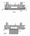
- Microfluidic flow cell shown in sections which in the exemplary embodiment shown serves to carry out an amplification process, comprises a plate-shaped substrate 1 and a film 2 that is welded or glued to the substrate 1 in a fluid-tight manner.
- a temperature-absorbing chamber 3 receiving a fluid is formed by a recess in the substrate 1 and the film 2, which covers this recess.
- the temperature control chamber 3 is connected via channels 4 and 5 to an inlet / outlet 6 and 7, respectively. It goes without saying that the temperature control chamber could deviate from or be connected to other chambers provided in the flow cell for other purposes.
- the film 2 consists of a composite of several layers, an inner layer 8 made of a plastic compatible with amplification reactions, a metal layer 9, in the example shown a layer of aluminum, and an outer layer 10 which, like the inner layer 8, consists of plastic .
- the inner layer 9 and the substrate 1 can be formed from the same material, which facilitates the fluid-tight welding of the film 2 to the substrate 1.
- a temperature control element 11 is placed on the wall of the temperature control chamber 3 formed by the film 2 and is kept at a temperature which corresponds to the desired temperature of the fluid in the temperature control chamber 3.
- the temperature control element 11 can be a heating or cooling element. In the first case, heat is transferred from the temperature control element 11 to the fluid in the temperature control chamber 3, in the second case, conversely, heat flows from the fluid to the temperature control element 11.
- the temperature control element 11 cannot lie flat against the film 2 in such a way that heat transfer is uniform over the entire contact surface.
- the temperature control element 11 due to the high thermal conductivity of the metal layer 9 contained in the film 2, which is primarily able to conduct heat in the lateral direction parallel to the film plane, there is a rapid heat exchange between the temperature control element 11 and the fluid in the temperature control chamber 3, whereby uniform heating of the fluid whose temperature matches the temperature of the temperature control element 11.
- the fluid can stand still in the temperature control chamber 3 during the temperature control or can flow through the temperature control chamber 3 at a speed that allows temperature compensation.
- the temperature control element 11a shown has suction channels 12 through which a negative pressure which pulls the film 2a against the temperature control element 11a can be generated, so that there is a uniform heat transfer between the temperature control element 11a and the film 2a over the contact surface.
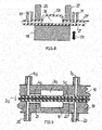
- a temperature control chamber 3b is essentially formed by a cap-like or chamber-like deformation 13 of a composite film 2b.
- An annular temperature control element 11b bears around the deformation 13 against the film 2b connected to a substrate 1b.
- the support of the film 2b by the substrate 1b permits an increased pressing force of the temperature control element 11b against the film 2b. Heat therefore transfers more evenly and is laterally conducted quickly through the metal layer contained in the film 2b into the center, so that temperature compensation between a fluid contained in the temperature control chamber 3b and the temperature control element 11b can take place in a short time.
- an annular temperature control element 11c is also an in Fig. 5 Embodiment shown used as the embodiment of Fig. 4 .
- a temperature chamber 3c is, as in the embodiments of 1 to 3 , formed by a recess in a substrate 1c.
- a composite film 2c covering the recess has a deformation 14 in the region of the recess, which increases the surface of the film 2c adjacent to the fluid while increasing the heat transfer performance, so that compared to the exemplary embodiment of FIG Fig. 4 an even faster adjustment of the temperature of the fluid in the temperature control chamber 3c to the temperature of the temperature control element 11c results.
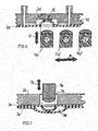
- Fig. 6 shows an embodiment with a film 2d, which in an area in which it forms a wall of a temperature control chamber 3d, is expandable by a temperature control element 11d into a recess forming the temperature control chamber 3d in a substrate 1d.
- a stop 15 on the bottom of the temperature control chamber 3d limits the expansion.
- the temperature control element 11d lies evenly against the elastically or plastically stretchable film 2d, so that there is a uniform heat transfer and temperature exchange between the temperature control element and the fluid over the entire contact surface.
- An arrangement of the temperature control element 11d and further temperature control elements 11d 'and 11d " can be shifted according to arrow 16, so that one of the temperature control elements 11d, 11d', 11d” can be extended according to arrow 17 by stretching the film 2d up to the stop 15.
- the fluid can then be successively tempered differently according to temperatures T1, T2 and T3 of the temperature control elements 11d, 11d ', 11d ".
- FIG. 7 An in Fig. 7
- the exemplary embodiment shown for a flow cell comprises a substrate 24 that is welded or glued to an arrangement of composite films 2e and 2e '.
- the composite films 2e, 2e ' are also connected to one another by welding or gluing.
- a temperature control element 11e which can be moved in the through opening 25 according to arrow 17e can the composite films 2e, 2e 'in the in Fig. 7 shown manner to form a temperature chamber 3e between the composite films 2e, 2e '.
- both composite films 2e, 2e ' are like those in FIG Fig. 1 shown film formed with a metal layer. Deviating from the shown In the exemplary embodiment, only the film 2e facing the temperature control element 11e could be designed as such a composite film.
- Fig. 8 shows an embodiment of a flow cell with a temperature control chamber 3f.
- the temperature control chamber 3f is formed from two composite foils 2f and 2f 'welded or glued together. While the composite film 2f is flat, the composite film 2f 'has a deformation 13f formed by deep drawing and is also connected to inlets / outlets 6f, 7f.
- a temperature control element 11f which is movable according to arrow 17f is opposite two temperature control elements 26 and 27 which can be moved in the opposite direction and which can be attached to the composite film 2f '. While the temperature control element 11f covers the entire side of the temperature control chamber 3f facing it and adjacent areas, the temperature control elements 26, 27 only bear against areas adjacent to the temperature control chamber 3f. Accordingly, heat is conducted laterally into the temperature control chamber.
- the free area formed by the deep-drawn deformation 13f can expand when the pressure in the temperature control chamber 3f builds up, partially compensating for the pressure.
- Fig. 9 shows an embodiment of a flow cell with a substrate 1g and a film 2g and a temperature control chamber 3g that the flow cell of Fig. 1 corresponds.
- a temperature control element 11g is not formed by a fixed temperature control body, as in the previous exemplary embodiments, but rather comprises a chamber 18 arranged symmetrically to the temperature control chamber 3g for receiving a temperature-regulating fluid.
- the chamber 18 is located in a recess in a substrate 19 which is connected to the composite film 2g in the same way as the substrate 1g.
- the chamber 18 receives a fluid maintained at a certain temperature, which in the exemplary embodiment shown enters the chamber 18 via an inlet 20 and a channel 21 and flows out via a channel 22 and an outlet 23.
- the substrate 1g and the substrate 19 consist of the same material.
- An inner layer 8g of the film 2g is also similar in material to the outer layer 10g facing the substrate 19.
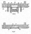
- Fig. 10 flow cell shown differs from the flow cell of Fig. 1 in that a valve with an actuator element 28 and 29 is provided in channels 4h and 5h, which are connected to a temperature control chamber 3h.
- the respective actuator element presses a composite film 2h in the closed state of the valve against a valve seat 30 or 31.
- a temperature control element 11 h has a recess 32 in the middle of its temperature control surface that can be placed against the film 2 h, into which the composite film 2 h can expand during temperature control with increasing internal pressure in the temperature control chamber 3 h.
- the actuators 28, 29 can be connected in one piece to the temperature control element 11h and can be moved together with it.
- Fig. 11 shows a flow cell with a chamber 3i, which initially serves as a storage chamber for a reagent 33. At predetermined breaking points at 34 and 35, openings can be formed which allow access to the reagent 33 and the further use of the chamber 3i as a temperature control chamber.
Landscapes
- Chemical & Material Sciences (AREA)
- Health & Medical Sciences (AREA)
- Clinical Laboratory Science (AREA)
- Chemical Kinetics & Catalysis (AREA)
- General Health & Medical Sciences (AREA)
- Analytical Chemistry (AREA)
- Hematology (AREA)
- Dispersion Chemistry (AREA)
- Life Sciences & Earth Sciences (AREA)
- Biochemistry (AREA)
- Molecular Biology (AREA)
- Physical Or Chemical Processes And Apparatus (AREA)
Description
- Die Erfindung betrifft eine Anordnung aus einer Flusszelle und einem Temperierelement gemäß Anspruch 1.
- Mikrofluidische Flusszellen werden, insbesondere als Einwegprodukte, in zunehmendem Maße in der Analytik und Diagnostik oder in der Medizin zur Konditionierung von Flüssigkeiten, bevor sie in den menschlichen Körper appliziert werden, sowie auch zu Synthesezwecken eingesetzt.
- Während sich die Funktion einer Flusszelle in der Temperierung eines Fluids erschöpfen kann, bilden Temperiereinrichtungen häufig nur Bestandteile von Flusszellen mit weitaus umfangreicherer Funktionalität. Insbesondere in Flusszellen zur Durchführung molekulargenetischer Analysen einschließlich von PCR- oder anderer Nukleinsäure amplifizierender Prozessen ist die Temperierfunktion von großer Bedeutung, indem die Amplifikationsreaktion konstante oder wechselnde, über der Umgebungstemperatur liegende Reaktionstemperaturen, typischerweise zwischen 30°C und 95°C, erfordert. Die Herstellung temperaturbeständiger Flusszellen mit reproduzierbaren Temperierungseigenschaften, welche einen besonders schnellen und homogenen Temperaturübergang zwischen einem aktiven Temperierelement und dem zu temperierenden Fluid erlauben, insbesondere die Herstellung solcher Flusszellen als preiswerte Einwegprodukte, stellt die Fertigung vor erhebliche Probleme.
- Eine Flusszelle mit einer Temperiereinrichtung ist aus der
US 6,613,560 B1 bekannt. Die Flusszelle dient der Durchführung des PCR-Prozesses. Eine Reaktionskammer für den PCR-Prozess bildet gleichzeitig die Temperierkammer. Die Temperierkammer ist durch eine Ausnehmung in einem Substrat und die eingangs genannte dünne, wärmeübertragende Folie begrenzt, welche die Ausnehmung abdeckt. Nachteilig für den Temperierungsprozess ist die geringe Wärmeleitfähigkeit von Kunststoffen, daher sind Folien mit geringer Foliendicke im Bereich von 50-200µm bevorzugt. Die Herstellung, Handhabung und Montage solcher dünnen Folien ist sehr aufwendig. Nachteilig bildet die Abdeckfolie aufgrund ihrer geringen mechanischen Steifigkeit keine exakte Ebene. Ebenso können thermische und mechanische Einflüsse bei der Montage der Folie mittels Klebe- oder Schweißprozessen leicht zu Verformungen der Folie und damit zu Abweichungen von der Ebene im Bereich von einigen 10-100 µm führen. Dies erschwert das Einkoppeln von Wärme durch Andrücken eines Temperierelements, wobei vor allem verbleibende Luftspalte den Wärmübergang beeinträchtigen und einen schnellen Ausgleich zwischen der Temperatur des Temperierelements und der Temperatur des Fluids in der Temperierkammer, insbesondere dessen gleichmäßige Erwärmung oder Abkühlung, verhindern. Reproduzierbare Temperierungseigenschaften lassen sich insbesondere unter den Bedingungen einer preisgünstigen Massenfertigung dieser Flusszelle nicht erreichen. - Anordnungen der eingangs erwähnten Art mit einer eine Metallschicht aufweisenden Verbundfolie gehen aus der
WO 02/01181 A2 EP 1 878 497 A1 , derEP 1 710 016 A2 , derUS 2010/311616 A1 , derWO 2008/006617 A2 und derEP 1 878 495 A1 hervor. - Flusszellen mit Temperierkammern und Temperierelemente umfassende Anordnungen gehen aus der
US 2005/0153430 A1 und derWO 2008/157801 A2 hervor. - Die Metallschicht der Folie sorgt aufgrund ihrer hohen, im Vergleich zum Kunststoff typischerweise ca. 1000fach höheren Wärmeleitfähigkeit für eine schnelle Wärmeausbreitung auch lateral, d.h. parallel zur Folienebene. Selbst bei nur teilweisem Anliegen eines Temperierelements an der Folie nimmt die Folie daher ausreichend schnell und gleichmäßig die Temperatur des Temperierelements an und überträgt sie weiter auf das Fluid. Fertigungsbedingte Schwankungen der Größe der Kontaktfläche zwischen Temperierelement und Folie fallen nicht ins Gewicht.
- In einer bevorzugten Ausführungsform der Erfindung besteht die dem Fluid zugewandte Kunststoffschicht aus einem mit der Amplifikationsreaktion kompatiblen Kunststoff, vorzugsweise einem Olefinpolymer, wie PP, PE, COC oder PC.
- Die wenigstens eine Metallschicht weist vorzugsweise Aluminium oder ein magnetisierbares Metall, wie z.B. Nickel, auf. In letzterem Fall lässt sich durch Magnetkraft die Anhaftung eines Temperierelements an der Folie und damit der Wärmeübergang zwischen dem Temperierelement und der Folie verbessern.
- Auch die dem Temperierelement zugewandte Folienschicht der Verbundfolie kann aus einem Kunststoff bestehen, insbesondere demjenigen Kunststoff, aus dem auch die dem Fluid zugewandte Schicht hergestellt ist. Zweckmäßig besteht die dem Temperierelement zugewandte Schicht aus einem Material, das einer Klebeanhaftung der Folie am Temperierelement entgegenwirkt.
- In der bevorzugten Ausführungsform der Erfindung liegt die Dicke der die Folie bildenden Schichten jeweils zwischen 1 µm und 100 µm.
- Während es möglich wäre, die Temperierkammer ausschließlich aus der dünnen Verbundfolie herzustellen, beispielsweise durch zwei in entgegengesetzten Richtungen tiefgezogene, miteinander verschweißte oder verklebte Folienteile oder ein tiefgezogenes Folienteil verschweißt mit einem ebenen unverformten Folienteil, ist gemäß der Erfindung die Temperierkammer durch eine mit der Verbundfolie abgedeckte Ausnehmung in einem bevorzugt unter preiswertem Spritzgießen hergestellten Substrat gebildet und die Verbundfolie mit dem Substrat verbunden, vorzugsweise verschweißt oder verklebt.
- Vorzugsweise ist die Folie mit einer ebenen, an die Ausnehmung grenzenden Oberfläche des Substrats verbunden.
- Das Substrat kann aus dem gleichen Kunststoff wie die dem Fluid zugewandte Schicht der Verbundfolie bestehen und somit die gesamte Temperierkammer aus nur einem Material gebildet sein, welches mit den zu temperierenden Fluiden kompatibel ist.
- Gemäß der Erfindung weist das Temperierelement einen festen, zur Wärmeübertragung gegen die Verbundfolie anlegbaren Temperierkörper auf.
- Das Temperierelement kann gemäß der Erfindung nur in einem an die Temperierkammer angrenzenden Randbereich, in dem die Verbundfolie z.B. mit der Oberfläche des Substrats verbunden ist, anliegen. Zweckmäßig ist die Folie in dem Randbereich derart abgestützt, dass das Temperierelement unter hohem Anpressdruck an die Folie anlegbar ist. Ist die Temperierkammer während der Temperierung hermetisch abgeschlossen, so hat das Anlegen des Temperierelements nur an einen Teil der die Temperierkammer bildenden Verbundfolie den Vorteil, dass ein durch Erwärmung und damit verbundene Ausdehnung des Fluids in der Kammer erzeugter Druckaufbau durch eine Ausdehnung der Verbundfolie und die damit einhergehende Vergrößerung des Volumens der Temperierkammer wenigstens teilweise kompensiert werden kann. Der dadurch verhinderte Druckaufbau in der Temperierkammer verringert wiederum die Anforderungen an Ventile die ggf. für einen hermetischen Abschluss der Kammer notwendig sind.
- In weiterer Ausgestaltung der Erfindung können Einrichtungen zum Ansaugen der Verbundfolie an den Temperierkörper gebildet sein. Durch festeren Andruck des Temperierkörpers gegen die Folie verbessert sich der Wärmekontakt. Besitzt die Verbundfolie eine magnetisierbare Metallschicht, kann der Temperierkörper mit einem Dauer- oder Elektromagneten versehen sein, um den Andruck des Temperierkörpers gegen die Folie durch magnetischer Wechselwirkung zu verbessern.
In einer Ausführungsform der Erfindung ist die Verbundfolie unter Vergrößerung ihrer das Fluid kontaktierenden Oberfläche tiefgezogen. - Die Verbundfolie kann innerhalb der Flusszelle weitere Funktionen erfüllen, z.B. Abdeckfunktionen oder eine Ventilfunktion.
- Es versteht sich, dass die Flusszelle mit der Temperierkammer einen Zu- und Abfluss für das Fluid, ggf. zum Durchfluss des Fluids durch die Kammer während der Temperierung, aufweisen kann. Ebenso kann die Flusszelle ferner Kanalstrukturen, Misch- und Verteilerelemente für die Fluide, Flüssigkeitsspeicher, Reaktions- und Detektionskammern und dergleichen Elemente aufweisen, welche nach dem Stand der Technik für die Durchführung von Analysen und Synthesen in mikrofluidischen Flusszellen gebräuchlich sind. Zweckmäßig erstreckt sich die Verbundfolie nur über den Teilbereich der Flusszelle, welcher die Temperierkammer beinhaltet, um zu sichern, dass während des Temperierprozesses keine oder wenig Wärme in die übrigen Bereiche der Flusszelle abfließt.
- Da das Temperieren eines Fluids in einer Temperierkammer immer mit einer Veränderung des Volumens des Fluids verbunden ist, kann es vorteilhaft sein, dass sich die Temperierkammer während des Temperierprozesses hermetisch gegenüber angrenzenden Kanal- oder/und Funktionsbereichen verschließen lässt. Dies kann insbesondere bei Erwärmungen bis nahe an die Siedetemperatur des Fluids erforderlich sein. Dadurch wird ein aus Volumenänderung und/oder partieller Dampfbildung resultierender Abgang des Fluids aus der Temperierkammer unterbunden. Durch Lösbarkeit des Verschlusses kann das Fluid nach dem Temperierprozess weitertransportiert, -verarbeitet oder, wie z.B. bei molekulargenetischen Analysen, analysiert werden. Zum Verschließen ist es vorteilhaft, im kanalförmigen Zu- und Abfluss der Temperierkammer einen Ventilsitz zu bilden, wobei im Bereich des Ventilsitzes die Verbundfolie nicht fest mit dem Substrat verbunden ist, sondern lose und eben am Substrat anliegt. Die Dehnbarkeit der Verbundfolie erlaubt es, dass ein Fluid unter Druck vor oder nach dem Temperierprozess zwischen dem Ventilsitz und der Verbundfolie hindurchtreten und in die Kammer oder aus der Kammer heraustransportiert werden kann. Während der Temperierung werden der Zu- und Ablauf hermetisch verschlossen, indem mechanische Stempel einer externen Aktuierungseinrichtung an die im Bereich der Ventilsitze an dem Substrat anliegende Verbundfolie angedrückt werden.
- Die erfindungsgemäße Temperierkammer kann ferner als Flüssigkeitsspeicher dienen, um z.B. ein Reagenz vor dessen Verwendung in der Flusszelle zu speichern. Das Volumen der gespeicherten Reagenz kann dabei kleiner als das der Temperier- und Speicherkammer sein, sodass die Kammer z.B. vor einer Temperierung noch mit einem zu analysierenden und mit dem Reagenz zu mischenden Fluid vollständig oder teilweise aufgefüllt werden kann. Bei Nutzung der Temperierkammer als Speicherkammer kann vorteilhaft ein kanalförmiger Zu- und Abfluss der Temperierkammer geometrisch unterbrochen und im unterbrochenen Kanalbereich die Verbundfolie fest mit dem Substrat z.B. durch Schweißen unter Bildung einer den Kanal verschließenden Siegelnaht verbunden werden. Nach Öffnen der Siegelnaht lassen sich die Fluide mittels Druck in die Kammer hinein- und aus dieser heraustransportieren und die Verschlussstellen fortan als Ventile nutzen. Die Metallschicht in der die Speicherkammer begrenzenden Verbundfolie verhindert einen Flüssigkeits- oder Gasdurchtritt durch die Kammerwand während der Lagerung.
- Die Erfindung wird nachfolgend anhand von Ausführungsbeispielen und der beiliegenden, sich auf diese Ausführungsbeispiele beziehenden Zeichnungen weiter erläutert. Es zeigen:
- Fig. 1
- einen Ausschnitt aus einer eine Temperierkammer aufweisenden Flusszelle,
- Fig. 2
- die Flusszelle von
Fig. 1 mit einem angesetzten Temperierelement, - Fig. 3
- die Flusszelle von
Fig. 1 mit einem Ansaugkanäle aufweisenden Temperierelement, - Fig. 4
- eine Flusszelle mit einer tiefgezogen Folie und ein Temperierelement,
- Fig. 5
- eine weitere Flusszelle mit einer tiefgezogenen Folie,
- Fig. 6
- eine Flusszelle mit einer in eine Ausnehmung in einem Substrat hinein durch Temperierelemente dehnbaren Folie,
- Fig. 7
- eine Flusszelle mit einer aus zwei dehnbaren Verbundfolien durch Auslenkung eines Temperierelements gebildeten Temperierkammer,
- Fig. 8
- eine Flusszelle mit einer aus zwei dehnbaren Verbundfolien gebildeten Temperierkammer mit Temperierelementen auf einander gegenüberliegenden Seiten,
- Fig. 9
- eine Flusszelle gemäß
Fig. 1 mit einem ein Temperierfluid führenden Temperierelement, - Fig. 10
- eine Flusszelle mit sich an eine Temperierkammer anschließenden Ventilbereichen, und
- Fig. 11
- eine Flusszelle mit einer als Speicherkammer dienenden Temperierkammer.
- Eine in
Fig. 1 ausschnittsweise dargestellte mikrofluidische Flusszelle, die in dem gezeigten Ausführungsbeispiel der Durchführung eines Amplifikationsprozesses dient, umfasst ein plattenförmiges Substrat 1 und eine mit dem Substrat 1 fluiddicht verschweißte oder verklebte Folie 2. - Durch eine Ausnehmung in dem Substrat 1 und der Folie 2, welche diese Ausnehmung abdeckt, ist eine ein Fluid aufnehmende Temperierkammer 3 gebildet. Die Temperierkammer 3 steht über Kanäle 4 und 5 mit je einem Ein-/ Auslass 6 bzw. 7 in Verbindung. Es versteht sich, dass die Temperierkammer hiervon abweichend mit anderen, in der Flusszelle zu anderen Zwecken vorgesehenen Kammern verbunden oder verbindbar sein könnte.
- Die Folie 2 besteht in dem gezeigten Ausführungsbeispiel aus einem Verbund mehrerer Schichten, einer Innenschicht 8 aus einem mit Amplifikationsreaktionen verträglichen Kunststoff, einer Metallschicht 9, in dem gezeigten Beispiel aus einer Schicht Aluminium, und einer Außenschicht 10, die wie die Innenschicht 8 aus Kunststoff besteht. Die Innenschicht 9 und das Substrat 1 können aus dem gleichen Material gebildet sein, was die fluiddichte Verschweißung der Folie 2 mit dem Substrat 1 erleichtert.
- In den nachfolgenden
Figuren 2 bis 6 ist die aus mehreren Schichten bestehende Verbundfolie 2 der Einfachheit halber ohne die einzelnen Schichten dargestellt. - Um ein in der Temperierkammer 3 befindliches Fluid auf eine gewünschte, z.B. im Rahmen der Gesamtfunktion der Flusszelle erforderliche Reaktionstemperatur zu bringen, wird gemäß
Fig. 2 an die durch die Folie 2 gebildete Wand der Temperierkammer 3 ein Temperierelement 11 angelegt, das auf einer Temperatur gehalten wird, die der gewünschten Temperatur des Fluids in der Temperierkammer 3 entspricht. - Je nach gewünschter Fluidtemperatur kann es sich bei dem Temperierelement 11 um ein Heiz- oder Kühlelement handeln. In ersterem Fall geht Wärme vom Temperierelement 11 auf das Fluid in der Temperierkammer 3 über, im zweiten Fall fließt umgekehrt Wärme vom Fluid zum Temperierelement 11.
- Infolge hoher Flexibilität der dünnen Folie 2, deren Gesamtschichtdicke sich im Bereich zwischen 3 µm und 300 µm bewegt, kann das Temperierelement 11 an der Folie 2 nicht derart plan anliegen, dass sich ein über die gesamte Anlagefläche gleichmäßiger Wärmeübergang ergibt. Durch die hohe Wärmeleitfähigkeit der in der Folie 2 enthaltenen Metallschicht 9 jedoch, die vor allem zur Wärmeleitung in lateraler Richtung parallel zur Folienebene imstande ist, kommt es dennoch zu einem schnellen Wärmeaustausch zwischen dem Temperierelement 11 und dem Fluid in der Temperierkammer 3, wobei sich bei gleichmäßiger Erwärmung des Fluids dessen Temperatur der Temperatur des Temperierelements 11 angleicht.
- Es versteht sich, dass das Fluid während der Temperierung in der Temperierkammer 3 stillstehen oder die Temperierkammer 3 mit einer den Temperaturausgleich zulassenden Geschwindigkeit durchströmen kann.
- Ein in
Fig. 3 gezeigtes Temperierelement 11a weist Saugkanäle 12 auf, durch die ein die Folie 2a gegen das Temperierelement 11a ziehender Unterdruck erzeugt werden kann, sodass sich ein über die Anlagefläche gleichmäßiger Wärmeübergang zwischen dem Temperierelement 11a und der Folie 2a ergibt. - In den nachfolgenden Figuren sind gleiche oder gleichwirkende Teile mit derselben Bezugszahl wie in den vorangehenden Figuren bezeichnet, wobei der betreffenden Bezugszahl der Buchstabe a, b usw. beigefügt ist.
- Bei einem in
Fig. 4 gezeigten Ausführungsbeispiel ist eine Temperierkammer 3b im Wesentlichen durch eine kappen- oder kammerartige Verformung 13 einer Verbundfolie 2b gebildet. Ein ringförmiges Temperierelement 11 b liegt um die Verformung 13 herum gegen die mit einem Substrat 1 b verbundene Folie 2b an. Die Abstützung der Folie 2b durch das Substrat 1 b lässt eine erhöhte Anpresskraft des Temperierelements 11 b gegen die Folie 2b zu. Wärme geht daher gleichmäßiger über und wird lateral durch die in der Folie 2b enthaltene Metallschicht schnell in die Mitte geleitet, sodass ein Temperaturausgleich zwischen einem in der Temperierkammer 3b enthaltenen Fluid und dem Temperierelement 11 b in kurzer Zeit erfolgen kann. - Auch ein in
Fig. 5 gezeigtes Ausführungsbeispiel verwendet, wie das Ausführungsbeispiel vonFig. 4 , ein ringförmiges Temperierelement 11c. Eine Temperierkammer 3c ist, wie bei den Ausführungsbeispielen vonFig. 1 bis 3 , durch eine Ausnehmung in einem Substrat 1c gebildet. Eine die Ausnehmung abdeckende Verbundfolie 2c weist im Bereich der Ausnehmung eine Verformung 14 auf, welche die an das Fluid angrenzende Oberfläche der Folie 2c unter Erhöhung der Wärmeübergangsleistung vergrößert, sodass sich gegenüber dem Ausführungsbeispiel vonFig. 4 eine noch schnellere Angleichung der Temperatur des Fluids in der Temperierkammer 3c an die Temperatur des Temperierelements 11c ergibt. -
Fig. 6 zeigt ein Ausführungsbeispiel mit einer Folie 2d, die in einem Bereich, in der sie eine Wand einer Temperierkammer 3d bildet, durch ein Temperierelement 11d in eine die Temperierkammer 3d bildende Ausnehmung in einem Substrat 1d hinein dehnbar ist. Ein Anschlag 15 am Boden der Temperierkammer 3d begrenzt die Dehnung. In dem inFig. 1 dargestellten Dehnungszustand liegt das Temperierelement 11d gleichmäßig gegen die elastisch oder plastisch dehnbare Folie 2d an, sodass sich ein über die gesamte Anlagefläche gleichmäßiger Wärmeübergang und Temperaturaustausch zwischen dem Temperierelement und dem Fluid ergibt. - Eine Anordnung aus dem Temperierelement 11d und weiteren Temperierelementen 11d' und 11d" lässt sich gemäß Pfeil 16 verschieben, sodass wahlweise eines der Temperierelemente 11d, 11d', 11d" gemäß Pfeil 17 unter Dehnung der Folie 2d bis an den Anschlag 15 ausfahrbar ist. Das Fluid lässt sich dann aufeinanderfolgend entsprechend Temperaturen T1, T2 und T3 der Temperierelemente 11d, 11d', 11d" unterschiedlich temperieren.
- Ein in
Fig. 7 gezeigtes Ausführungsbeispiel für eine Flusszelle umfasst ein Substrat 24, dass mit einer Anordnung aus Verbundfolien 2e und 2e' verschweißt oder verklebt ist. - Außer in einem Bereich vor einer Durchgangsöffnung 25 in dem Substrat 24 und einer an diesen Bereich angrenzenden Umgebung sind die Verbundfolien 2e, 2e' auch miteinander durch Verschweißung oder Verklebung verbunden.
- Ein in der Durchgangsöffnung 25 gemäß Pfeil 17e bewegbares Temperierelement 11e, kann die Verbundfolien 2e, 2e' in der in
Fig. 7 gezeigten Weise unter Bildung einer Temperierkammer 3e zwischen den Verbundfolien 2e, 2e' ausdehnen. In dem gezeigten Ausführungsbeispiel sind beide Verbundfolien 2e, 2e' wie die inFig. 1 gezeigte Folie mit einer Metallschicht ausgebildet. Abweichend von dem gezeigten Ausführungsbeispiel könnte auch nur die dem Temperierelement 11e zugewandte Folie 2e als eine solche Verbundfolie ausgebildet sein. - In die Temperierkammer 3e einmündende Zu- oder Abflüsse sind in
Fig. 7 nicht gezeigt. - Aus
Fig. 8 geht ein Ausführungsbeispiel für eine Flusszelle mit einer Temperierkammer 3f hervor. Die Temperierkammer 3f ist aus zwei miteinander verschweißten oder verklebten Verbundfolien 2f und 2f' gebildet. Während die Verbundfolie 2f eben ist, weist die Verbundfolie 2f' eine durch Tiefziehen gebildete Verformung 13f auf und ist ferner mit Ein-/Auslässen 6f, 7f verbunden. - Einem gemäß Pfeil 17f bewegbaren Temperierelement 11f liegen zwei in entgegengesetzten Richtung bewegbare, an die Verbundfolie 2f' ansetzbare Temperierelemente 26 und 27 gegenüber. Während das Temperierelement 11f die gesamte, ihm zugewandte Seite der Temperierkammer 3f und angrenzende Bereiche abdeckt, liegen die Temperierelemente 26, 27 nur gegen an die Temperierkammer 3f angrenzende Bereiche an. Entsprechend wird Wärme lateral in die Temperierkammer geleitet. Der freie, durch die tiefgezogene Verformung 13f gebildete Bereich kann sich bei Druckaufbau in der Temperierkammer 3f unter teilweisem Ausgleich des Drucks ausdehnen.
-
Fig. 9 zeigt ein Ausführungsbeispiel für eine Flusszelle mit einem Substrat 1g und einer Folie 2g und einer Temperierkammer 3g, das der Flusszelle vonFig. 1 entspricht. - Ein Temperierelement 11g ist in dem gezeigten Ausführungsbeispiel jedoch nicht, wie bei den vorangehenden Ausführungsbeispielen, durch einen festen Temperierkörper gebildet, sondern umfasst eine symmetrisch zu der Temperierkammer 3g angeordnete Kammer 18 für die Aufnahme eines temperierenden Fluids. Die Kammer 18 befindet sich in einer Ausnehmung in einem Substrat 19, das mit der Verbundfolie 2g in gleicher Weise verbunden ist, wie das Substrat 1g. Die Kammer 18 nimmt ein auf einer bestimmten Temperatur gehaltenes Fluid auf, das in dem gezeigten Ausführungsbeispiel über einen Einlass 20 und einen Kanal 21 in die Kammer 18 hinein gelangt und über einen Kanal 22 und einen Auslass 23 abfließt. In dem gezeigten Ausführungsbeispiel bestehen das Substrat 1g und das Substrat 19 aus dem gleichen Material. Auch eine Innenschicht 8g der Folie 2g gleicht im Material der dem Substrat 19 zugewandten Außenschicht 10g.
- Eine in
Fig. 10 gezeigte Flusszelle unterscheidet sich von der Flusszelle vonFig. 1 dadurch, dass in Kanälen 4h und 5h, die mit einer Temperierkammer 3h verbunden sind, jeweils ein Ventil mit einem Aktuatorelement 28 bzw. 29 vorgesehen ist. Das jeweilige Aktuatorelement drückt eine Verbundfolie 2h im geschlossenen Zustand des Ventils gegen einen Ventilsitz 30 bzw. 31. - Ein Temperierelement 11 h weist in der Mitte seiner gegen die Folie 2h anlegbaren Temperierfläche eine Ausnehmung 32 auf, in die hinein sich während einer Temperierung die Verbundfolie 2h bei in der Temperierkammer 3h steigendem Innendruck ausdehnen kann.
- Die Aktuatoren 28, 29 können einstückig mit dem Temperierelement 11h verbunden und gemeinsam mit diesem bewegbar sein.
-
Fig. 11 zeigt eine Flusszelle mit einer Kammer 3i, die zunächst als Speicherkammer für eine Reagenz 33 dient. An Sollbruchstellen bei 34 und 35 lassen sich Öffnungen bilden, die einen Zugriff auf das Reagenz 33 sowie die weitere Nutzung der Kammer 3i als Temperierkammer ermöglichen.
Claims (12)
- Anordnung aus einer Flusszelle und einem Temperierelement, mit einer ein zu temperiendes Fluid aufnehmenen Temperierkammer (3), deren Begrenzungswand wenigstens teilweise durch eine dünne, Wärme zwischen dem Temperierelement (11) und dem Fluid übertragende Folie (2) gebildet ist, wobei die Folie als Verbundfolie (2) mit mehreren miteinander verbundenen Schichten (8-10) ausgebildet ist, die dem Fluid zugewandte Schicht (8) eine Kunststoffschicht ist, wenigstens eine weitere Schicht (9) aus einem Metall besteht, die Temperierkammer (3) durch eine mit der Verbundfolie (2) abgedeckte Ausnehmung in einem Substrat (1) gebildet und die Verbundfolie (2) mit dem Substrat verbunden ist,
dadurch gekennzeichnet,
dass die Verbundfolie (2a) durch in dem Temperierelement (11a) gebildete Saugkanäle (12) sich gegen das Temperierelement (11a) anziehen lässt oder dass das Temperierelement (11, 11b, 11c) nur in einem an die Ausnehmung in dem Substrat (1, 1b, 1c) grenzenden Randbereich, in dem die Verbundfolie (2,2b,2c) mit der Oberfläche des Substrats (1, 1b, 1c) verbunden ist, gegen die Verbundfolie (2,2b,2c) anliegt. - Anordnung nach Anspruch 1,
dadurch gekennzeichnet,
dass die dem Fluid zugewandte Kunststoffschicht (8) aus einem mit einer Amplifikationsreaktion kompatiblen Kunststoff besteht, vorzugsweise einem Olefinpolymer, wie PP, PE, COC oder PC. - Anordnung nach Anspruch 1 oder 2,
dadurch gekennzeichnet,
dass die wenigstens eine Metallschicht aus Aluminium oder einem magnetisierbaren Metall, z.B. Nickel, besteht. - Anordnung nach einem der Ansprüche 1 bis 3,
dadurch gekennzeichnet,
dass die dem Temperierelement (11) zugewandte Folienschicht (10) aus einem Kunststoff besteht, insbesondere demselben Kunststoff wie die dem Fluid zugewandte Schicht (8). - Anordnung nach einem der Ansprüche 1 bis 4,
dadurch gekennzeichnet,
dass die jeweilige Schichtdicke zwischen 1 µm und 100 µm liegt. - Anordnung nach einem der Ansprüche 1 bis 5,
dadurch gekennzeichnet,
dass die Verbundfolie (2) mit dem Substrat (1) verschweißt oder verklebt ist. - Anordnung nach einem der Ansprüche 1 bis 6,
dadurch gekennzeichnet,
dass die Temperierkammer (3h) durch wenigstens ein Ventil verschließbar ist und insbesondere in einem mit der Temperierkammer (3h) verbundenen, durch die Verbundfolie (2h) abgedeckten Kanal (4h, 5h) ein Ventilsitz (30,31), gegen den die Verbundfolie (2h) lose anliegt, gebildet ist. - Anordnung nach Anspruch 6 oder 7,
dadurch gekennzeichnet,
dass das Substrat (1) aus dem gleichen Kunststoff wie die dem Fluid zugewandte Schicht (8) der Verbundfolie (2) besteht. - Anordnung nach einem Ansprüche 1 bis 8,
dadurch gekennzeichnet,
dass die Temperierkammer (3i) als Speicherkammer nutzbar und mit wenigstens einem die Speicherkammer abschließenden Verschluss als Sollbruchstelle (34,35) zur Bildung einer Öffnung ausgebildet ist. - Anordnung nach einem der Ansprüche 1 bis 9,
dadurch gekennzeichnet,
dass die Verbundfolie (2c) unter Vergrößerung ihrer an das Fluid angrenzenden Oberfläche tiefgezogen, ist. - Anordnung nach einem der Ansprüche 1 bis 10,
dadurch gekennzeichnet,
dass der Verbundfolie (2) innerhalb der Flusszelle über die Wärmeübertragung hinaus als weitere Funktion wenigstens eine Abdeck- und/oder Ventilfunktion zukommt. - Anordnung nach einem der Ansprüche 1 bis 11,
dadurch gekennzeichnet,
dass die Flusszelle einen Zu- und einen Abfluss (6,7) für das Fluid zum Durchfluss durch die Temperierkammer während der Temperierung aufweist.
Priority Applications (2)
| Application Number | Priority Date | Filing Date | Title |
|---|---|---|---|
| EP12163321.8A EP2647435B1 (de) | 2012-04-05 | 2012-04-05 | Anordnung aus einer flusszelle und einem temperierelement |
| US13/856,194 US9149802B2 (en) | 2012-04-05 | 2013-04-03 | Flow cell with a temperature-control chamber |
Applications Claiming Priority (1)
| Application Number | Priority Date | Filing Date | Title |
|---|---|---|---|
| EP12163321.8A EP2647435B1 (de) | 2012-04-05 | 2012-04-05 | Anordnung aus einer flusszelle und einem temperierelement |
Publications (2)
| Publication Number | Publication Date |
|---|---|
| EP2647435A1 EP2647435A1 (de) | 2013-10-09 |
| EP2647435B1 true EP2647435B1 (de) | 2020-08-05 |
Family
ID=45937051
Family Applications (1)
| Application Number | Title | Priority Date | Filing Date |
|---|---|---|---|
| EP12163321.8A Active EP2647435B1 (de) | 2012-04-05 | 2012-04-05 | Anordnung aus einer flusszelle und einem temperierelement |
Country Status (2)
| Country | Link |
|---|---|
| US (1) | US9149802B2 (de) |
| EP (1) | EP2647435B1 (de) |
Families Citing this family (11)
| Publication number | Priority date | Publication date | Assignee | Title |
|---|---|---|---|---|
| US10139134B2 (en) * | 2010-12-21 | 2018-11-27 | Nec Corporation | Sample heating method and heating control device |
| GB2516669B (en) | 2013-07-29 | 2015-09-09 | Atlas Genetics Ltd | A method for processing a liquid sample in a fluidic cartridge |
| GB2516675A (en) | 2013-07-29 | 2015-02-04 | Atlas Genetics Ltd | A valve which depressurises, and a valve system |
| GB2516666B (en) | 2013-07-29 | 2015-09-09 | Atlas Genetics Ltd | Fluidic cartridge for nucleic acid amplification and detection |
| GB2516667A (en) | 2013-07-29 | 2015-02-04 | Atlas Genetics Ltd | An improved cartridge, cartridge reader and method for preventing reuse |
| GB2516672B (en) | 2013-07-29 | 2015-05-20 | Atlas Genetics Ltd | A system and method for expelling liquid from a fluidic cartridge |
| CN105980058A (zh) | 2014-01-07 | 2016-09-28 | 达克雷诊断器材有限公司 | 流体输送装置、系统和方法 |
| EP2962758B1 (de) | 2014-07-01 | 2017-07-19 | ThinXXS Microtechnology AG | Flusszelle mit einem speicherbereich und einem an einer sollbruchstelle aufschliessbaren transportkanal |
| EP3124118B1 (de) * | 2015-07-28 | 2018-02-28 | Panasonic Intellectual Property Management Co., Ltd. | Mikrokanalvorrichtung und pcr-verfahren |
| JP2019536993A (ja) * | 2016-10-07 | 2019-12-19 | ベーリンガー インゲルハイム フェトメディカ ゲーエムベーハーBoehringer Ingelheim Vetmedica GmbH | サンプルを検査するためのカートリッジ、分析システム、及び方法 |
| EP3818067B1 (de) | 2018-07-04 | 2025-06-18 | Ador Diagnostics Ltd. | System, vorrichtung und verfahren zur rechnergestützten automatischen diagnose |
Citations (2)
| Publication number | Priority date | Publication date | Assignee | Title |
|---|---|---|---|---|
| US20050153430A1 (en) * | 2003-11-28 | 2005-07-14 | Yoshimitsu Ohtaka | Nucleic acid detecting cassette, nucleic and detecting apparatus utilizing nucleic acid detecting cassette, and nucleic acid detecting system utilizing nucleic acid detecting cassette |
| WO2008157801A2 (en) * | 2007-06-21 | 2008-12-24 | Gen-Probe Incorporated | Instrument and receptacles for performing processes |
Family Cites Families (12)
| Publication number | Priority date | Publication date | Assignee | Title |
|---|---|---|---|---|
| US5074196A (en) * | 1990-09-28 | 1991-12-24 | Calspan Corporation | Flexible gas impermeable sandwich diaphragm |
| US6613560B1 (en) | 1994-10-19 | 2003-09-02 | Agilent Technologies, Inc. | PCR microreactor for amplifying DNA using microquantities of sample fluid |
| US6627159B1 (en) * | 2000-06-28 | 2003-09-30 | 3M Innovative Properties Company | Centrifugal filling of sample processing devices |
| US6692700B2 (en) * | 2001-02-14 | 2004-02-17 | Handylab, Inc. | Heat-reduction methods and systems related to microfluidic devices |
| US6575188B2 (en) * | 2001-07-26 | 2003-06-10 | Handylab, Inc. | Methods and systems for fluid control in microfluidic devices |
| EP2415524A2 (de) * | 2005-03-30 | 2012-02-08 | F. Hoffmann-La Roche AG | Abgedichtete Vorrichtung |
| EP1886727A1 (de) * | 2006-07-14 | 2008-02-13 | Roche Diagnostics GmbH | Vorrichtung zur Analyse |
| EP1878497A1 (de) * | 2006-07-14 | 2008-01-16 | Roche Diagnostics GmbH | Einwegartikel zur Analyse einer flüssigen probe durch Vervielfältigung von Nukleinsäuren |
| EP1878495A1 (de) * | 2006-07-14 | 2008-01-16 | Roche Diagnostics GmbH | Analysevorrichtung zur thermische Behandlung einer Flüssigkeit und/oder zur Überwachung einer deren Eigenschaften |
| TWI447393B (zh) * | 2007-10-26 | 2014-08-01 | Toppan Printing Co Ltd | 反應晶片及其製造方法 |
| DE102009009728A1 (de) * | 2009-02-19 | 2010-09-02 | Thinxxs Microtechnology Ag | Flusszelle mit integriertem Fluidspeicher |
| JP5797926B2 (ja) * | 2011-04-21 | 2015-10-21 | 株式会社エンプラス | 流体取扱装置およびその製造方法ならびに流体取扱システム |
-
2012
- 2012-04-05 EP EP12163321.8A patent/EP2647435B1/de active Active
-
2013
- 2013-04-03 US US13/856,194 patent/US9149802B2/en active Active
Patent Citations (2)
| Publication number | Priority date | Publication date | Assignee | Title |
|---|---|---|---|---|
| US20050153430A1 (en) * | 2003-11-28 | 2005-07-14 | Yoshimitsu Ohtaka | Nucleic acid detecting cassette, nucleic and detecting apparatus utilizing nucleic acid detecting cassette, and nucleic acid detecting system utilizing nucleic acid detecting cassette |
| WO2008157801A2 (en) * | 2007-06-21 | 2008-12-24 | Gen-Probe Incorporated | Instrument and receptacles for performing processes |
Also Published As
| Publication number | Publication date |
|---|---|
| EP2647435A1 (de) | 2013-10-09 |
| US9149802B2 (en) | 2015-10-06 |
| US20130263940A1 (en) | 2013-10-10 |
Similar Documents
| Publication | Publication Date | Title |
|---|---|---|
| EP2647435A1 (de) | Flusszelle mit einer Temperierkammer | |
| EP2138233B1 (de) | Mikrofluidische Folienstruktur zum Dosierren von Flüssigkeiten | |
| DE602004002407T2 (de) | Mikrofluidventil mit elektrischer öffnungssteuerung | |
| EP2686595B1 (de) | Mikrofluidisches ventil und mikrofluidische plattform | |
| DE102008002336A1 (de) | Quetschventil und Verfahren zu dessen Herstellung | |
| DE102012206042B4 (de) | Verfahren und Vorrichtung zur gezielten Prozessführung in einem Mikrofluidik-Prozessor mit integrierten aktiven Elementen | |
| EP3049186B1 (de) | Analyseeinheit zum durchführen einer polymerasekettenreaktion, verfahren zum betreiben einer solchen analyseeinheit und verfahren zum herstellen einer solchen analyseeinheit | |
| EP2796200B1 (de) | Mikrofluidische analysekartusche und verfahren zu ihrer herstellung | |
| DE102011083920B4 (de) | Verfahren und vorrichtung zum erzeugen von fluidisch voneinander separierten teilvolumina einer flüssigkeit | |
| DE202012001202U1 (de) | Ventilstecker | |
| EP2576065A1 (de) | Flusszelle mit hohlraum und diaphragma | |
| EP3406340B1 (de) | Flusszelle mit gehäusebauteil | |
| EP2567092B1 (de) | Mikrofluidisches bauteil, insbesondere peristaltische mikropumpe, und verfahren zu dessen herstellung | |
| WO2010031559A1 (de) | Mikrofluidisches ventil, mikrofluidische pumpe, mikrofluidisches system und ein herstellungsverfahren | |
| DE102004050510B4 (de) | Verfahren zur Ventilsteuerung bei der Thermozyklisierung einer Substanz zwecks PCR und zugehörige Anordnung | |
| EP3866973A1 (de) | Probenbehälter | |
| EP3094740B1 (de) | Analyseeinheit zum durchführen einer verschachtelten polymerasekettenreaktion, analysevorrichtung, verfahren zum betreiben einer solchen analyseeinheit und verfahren zum herstellen einer solchen analyseeinheit | |
| EP4433212B1 (de) | Kartusche für ein rotationsbasiertes und einen wärmeeintrag nutzendes analyseverfahren | |
| DE102023100893A1 (de) | Ventilvorrichtung zur Umschaltung eines Strömungsweges eines Fluids, Temperieranordnung und Verfahren zur Herstellung | |
| EP2805771B1 (de) | Fluidbereitstellungseinheit mit einer Ventilvorrichtung und Verfahren zum Betreiben einer Fluidbereitstellungseinheit | |
| WO2024126241A1 (de) | Mikrofluidische vorrichtung, insbesondere kartusche, mit einem pad zur wärmeübertragung auf ein analysesubstrat | |
| DE102013207193A1 (de) | Mikrohydraulisches System, insbesondere zum Einsatz in planaren Mikrofluidiklaboren | |
| EP3263218A1 (de) | Mikrofluidikchip mit einem funktionellen bereich, der mit einem flexiblen oder verformbaren deckel abgedeckt ist, und mikrofluidiksystem | |
| DE102016014056A1 (de) | Mikrofluidikchip mit einem funktionellen Bereich, der mit einem flexiblen oder verformbaren Deckel ist, und Mikrofluidiksystem | |
| DE102008036440A1 (de) | Thermoformvorrichtung mit verbesserter Druckflanschkühlung |
Legal Events
| Date | Code | Title | Description |
|---|---|---|---|
| PUAI | Public reference made under article 153(3) epc to a published international application that has entered the european phase |
Free format text: ORIGINAL CODE: 0009012 |
|
| AK | Designated contracting states |
Kind code of ref document: A1 Designated state(s): AL AT BE BG CH CY CZ DE DK EE ES FI FR GB GR HR HU IE IS IT LI LT LU LV MC MK MT NL NO PL PT RO RS SE SI SK SM TR |
|
| AX | Request for extension of the european patent |
Extension state: BA ME |
|
| 17P | Request for examination filed |
Effective date: 20140409 |
|
| RBV | Designated contracting states (corrected) |
Designated state(s): AL AT BE BG CH CY CZ DE DK EE ES FI FR GB GR HR HU IE IS IT LI LT LU LV MC MK MT NL NO PL PT RO RS SE SI SK SM TR |
|
| STAA | Information on the status of an ep patent application or granted ep patent |
Free format text: STATUS: EXAMINATION IS IN PROGRESS |
|
| 17Q | First examination report despatched |
Effective date: 20161222 |
|
| GRAP | Despatch of communication of intention to grant a patent |
Free format text: ORIGINAL CODE: EPIDOSNIGR1 |
|
| STAA | Information on the status of an ep patent application or granted ep patent |
Free format text: STATUS: GRANT OF PATENT IS INTENDED |
|
| INTG | Intention to grant announced |
Effective date: 20200306 |
|
| RIN1 | Information on inventor provided before grant (corrected) |
Inventor name: WEBER LUTZ |
|
| GRAS | Grant fee paid |
Free format text: ORIGINAL CODE: EPIDOSNIGR3 |
|
| GRAA | (expected) grant |
Free format text: ORIGINAL CODE: 0009210 |
|
| STAA | Information on the status of an ep patent application or granted ep patent |
Free format text: STATUS: THE PATENT HAS BEEN GRANTED |
|
| AK | Designated contracting states |
Kind code of ref document: B1 Designated state(s): AL AT BE BG CH CY CZ DE DK EE ES FI FR GB GR HR HU IE IS IT LI LT LU LV MC MK MT NL NO PL PT RO RS SE SI SK SM TR |
|
| REG | Reference to a national code |
Ref country code: GB Ref legal event code: FG4D Free format text: NOT ENGLISH |
|
| RIN1 | Information on inventor provided before grant (corrected) |
Inventor name: WEBER LUTZ |
|
| REG | Reference to a national code |
Ref country code: CH Ref legal event code: EP |
|
| REG | Reference to a national code |
Ref country code: AT Ref legal event code: REF Ref document number: 1297946 Country of ref document: AT Kind code of ref document: T Effective date: 20200815 |
|
| REG | Reference to a national code |
Ref country code: DE Ref legal event code: R096 Ref document number: 502012016257 Country of ref document: DE |
|
| REG | Reference to a national code |
Ref country code: IE Ref legal event code: FG4D Free format text: LANGUAGE OF EP DOCUMENT: GERMAN |
|
| REG | Reference to a national code |
Ref country code: CH Ref legal event code: NV Representative=s name: ALDO ROEMPLER PATENTANWALT, CH |
|
| REG | Reference to a national code |
Ref country code: LT Ref legal event code: MG4D |
|
| REG | Reference to a national code |
Ref country code: NL Ref legal event code: MP Effective date: 20200805 |
|
| PG25 | Lapsed in a contracting state [announced via postgrant information from national office to epo] |
Ref country code: FI Free format text: LAPSE BECAUSE OF FAILURE TO SUBMIT A TRANSLATION OF THE DESCRIPTION OR TO PAY THE FEE WITHIN THE PRESCRIBED TIME-LIMIT Effective date: 20200805 Ref country code: NO Free format text: LAPSE BECAUSE OF FAILURE TO SUBMIT A TRANSLATION OF THE DESCRIPTION OR TO PAY THE FEE WITHIN THE PRESCRIBED TIME-LIMIT Effective date: 20201105 Ref country code: GR Free format text: LAPSE BECAUSE OF FAILURE TO SUBMIT A TRANSLATION OF THE DESCRIPTION OR TO PAY THE FEE WITHIN THE PRESCRIBED TIME-LIMIT Effective date: 20201106 Ref country code: HR Free format text: LAPSE BECAUSE OF FAILURE TO SUBMIT A TRANSLATION OF THE DESCRIPTION OR TO PAY THE FEE WITHIN THE PRESCRIBED TIME-LIMIT Effective date: 20200805 Ref country code: LT Free format text: LAPSE BECAUSE OF FAILURE TO SUBMIT A TRANSLATION OF THE DESCRIPTION OR TO PAY THE FEE WITHIN THE PRESCRIBED TIME-LIMIT Effective date: 20200805 Ref country code: SE Free format text: LAPSE BECAUSE OF FAILURE TO SUBMIT A TRANSLATION OF THE DESCRIPTION OR TO PAY THE FEE WITHIN THE PRESCRIBED TIME-LIMIT Effective date: 20200805 Ref country code: BG Free format text: LAPSE BECAUSE OF FAILURE TO SUBMIT A TRANSLATION OF THE DESCRIPTION OR TO PAY THE FEE WITHIN THE PRESCRIBED TIME-LIMIT Effective date: 20201105 Ref country code: ES Free format text: LAPSE BECAUSE OF FAILURE TO SUBMIT A TRANSLATION OF THE DESCRIPTION OR TO PAY THE FEE WITHIN THE PRESCRIBED TIME-LIMIT Effective date: 20200805 Ref country code: PT Free format text: LAPSE BECAUSE OF FAILURE TO SUBMIT A TRANSLATION OF THE DESCRIPTION OR TO PAY THE FEE WITHIN THE PRESCRIBED TIME-LIMIT Effective date: 20201207 |
|
| PG25 | Lapsed in a contracting state [announced via postgrant information from national office to epo] |
Ref country code: LV Free format text: LAPSE BECAUSE OF FAILURE TO SUBMIT A TRANSLATION OF THE DESCRIPTION OR TO PAY THE FEE WITHIN THE PRESCRIBED TIME-LIMIT Effective date: 20200805 Ref country code: NL Free format text: LAPSE BECAUSE OF FAILURE TO SUBMIT A TRANSLATION OF THE DESCRIPTION OR TO PAY THE FEE WITHIN THE PRESCRIBED TIME-LIMIT Effective date: 20200805 Ref country code: PL Free format text: LAPSE BECAUSE OF FAILURE TO SUBMIT A TRANSLATION OF THE DESCRIPTION OR TO PAY THE FEE WITHIN THE PRESCRIBED TIME-LIMIT Effective date: 20200805 Ref country code: RS Free format text: LAPSE BECAUSE OF FAILURE TO SUBMIT A TRANSLATION OF THE DESCRIPTION OR TO PAY THE FEE WITHIN THE PRESCRIBED TIME-LIMIT Effective date: 20200805 Ref country code: IS Free format text: LAPSE BECAUSE OF FAILURE TO SUBMIT A TRANSLATION OF THE DESCRIPTION OR TO PAY THE FEE WITHIN THE PRESCRIBED TIME-LIMIT Effective date: 20201205 |
|
| PG25 | Lapsed in a contracting state [announced via postgrant information from national office to epo] |
Ref country code: SM Free format text: LAPSE BECAUSE OF FAILURE TO SUBMIT A TRANSLATION OF THE DESCRIPTION OR TO PAY THE FEE WITHIN THE PRESCRIBED TIME-LIMIT Effective date: 20200805 Ref country code: RO Free format text: LAPSE BECAUSE OF FAILURE TO SUBMIT A TRANSLATION OF THE DESCRIPTION OR TO PAY THE FEE WITHIN THE PRESCRIBED TIME-LIMIT Effective date: 20200805 Ref country code: CZ Free format text: LAPSE BECAUSE OF FAILURE TO SUBMIT A TRANSLATION OF THE DESCRIPTION OR TO PAY THE FEE WITHIN THE PRESCRIBED TIME-LIMIT Effective date: 20200805 Ref country code: EE Free format text: LAPSE BECAUSE OF FAILURE TO SUBMIT A TRANSLATION OF THE DESCRIPTION OR TO PAY THE FEE WITHIN THE PRESCRIBED TIME-LIMIT Effective date: 20200805 Ref country code: DK Free format text: LAPSE BECAUSE OF FAILURE TO SUBMIT A TRANSLATION OF THE DESCRIPTION OR TO PAY THE FEE WITHIN THE PRESCRIBED TIME-LIMIT Effective date: 20200805 |
|
| REG | Reference to a national code |
Ref country code: DE Ref legal event code: R097 Ref document number: 502012016257 Country of ref document: DE |
|
| PG25 | Lapsed in a contracting state [announced via postgrant information from national office to epo] |
Ref country code: AL Free format text: LAPSE BECAUSE OF FAILURE TO SUBMIT A TRANSLATION OF THE DESCRIPTION OR TO PAY THE FEE WITHIN THE PRESCRIBED TIME-LIMIT Effective date: 20200805 |
|
| PLBE | No opposition filed within time limit |
Free format text: ORIGINAL CODE: 0009261 |
|
| STAA | Information on the status of an ep patent application or granted ep patent |
Free format text: STATUS: NO OPPOSITION FILED WITHIN TIME LIMIT |
|
| PG25 | Lapsed in a contracting state [announced via postgrant information from national office to epo] |
Ref country code: SK Free format text: LAPSE BECAUSE OF FAILURE TO SUBMIT A TRANSLATION OF THE DESCRIPTION OR TO PAY THE FEE WITHIN THE PRESCRIBED TIME-LIMIT Effective date: 20200805 |
|
| 26N | No opposition filed |
Effective date: 20210507 |
|
| PG25 | Lapsed in a contracting state [announced via postgrant information from national office to epo] |
Ref country code: IT Free format text: LAPSE BECAUSE OF FAILURE TO SUBMIT A TRANSLATION OF THE DESCRIPTION OR TO PAY THE FEE WITHIN THE PRESCRIBED TIME-LIMIT Effective date: 20200805 |
|
| PG25 | Lapsed in a contracting state [announced via postgrant information from national office to epo] |
Ref country code: SI Free format text: LAPSE BECAUSE OF FAILURE TO SUBMIT A TRANSLATION OF THE DESCRIPTION OR TO PAY THE FEE WITHIN THE PRESCRIBED TIME-LIMIT Effective date: 20200805 |
|
| PG25 | Lapsed in a contracting state [announced via postgrant information from national office to epo] |
Ref country code: MC Free format text: LAPSE BECAUSE OF FAILURE TO SUBMIT A TRANSLATION OF THE DESCRIPTION OR TO PAY THE FEE WITHIN THE PRESCRIBED TIME-LIMIT Effective date: 20200805 |
|
| PG25 | Lapsed in a contracting state [announced via postgrant information from national office to epo] |
Ref country code: LU Free format text: LAPSE BECAUSE OF NON-PAYMENT OF DUE FEES Effective date: 20210405 |
|
| REG | Reference to a national code |
Ref country code: BE Ref legal event code: MM Effective date: 20210430 |
|
| PG25 | Lapsed in a contracting state [announced via postgrant information from national office to epo] |
Ref country code: IE Free format text: LAPSE BECAUSE OF NON-PAYMENT OF DUE FEES Effective date: 20210405 |
|
| REG | Reference to a national code |
Ref country code: DE Ref legal event code: R081 Ref document number: 502012016257 Country of ref document: DE Owner name: THINXXS MICROTECHNOLOGY GMBH, DE Free format text: FORMER OWNER: THINXXS MICROTECHNOLOGY AG, 66482 ZWEIBRUECKEN, DE |
|
| PG25 | Lapsed in a contracting state [announced via postgrant information from national office to epo] |
Ref country code: IS Free format text: LAPSE BECAUSE OF FAILURE TO SUBMIT A TRANSLATION OF THE DESCRIPTION OR TO PAY THE FEE WITHIN THE PRESCRIBED TIME-LIMIT Effective date: 20201205 |
|
| PG25 | Lapsed in a contracting state [announced via postgrant information from national office to epo] |
Ref country code: BE Free format text: LAPSE BECAUSE OF NON-PAYMENT OF DUE FEES Effective date: 20210430 |
|
| REG | Reference to a national code |
Ref country code: AT Ref legal event code: HC Ref document number: 1297946 Country of ref document: AT Kind code of ref document: T Owner name: THINXXS MICROTECHNOLOGY GMBH, DE Effective date: 20220628 |
|
| PG25 | Lapsed in a contracting state [announced via postgrant information from national office to epo] |
Ref country code: HU Free format text: LAPSE BECAUSE OF FAILURE TO SUBMIT A TRANSLATION OF THE DESCRIPTION OR TO PAY THE FEE WITHIN THE PRESCRIBED TIME-LIMIT; INVALID AB INITIO Effective date: 20120405 Ref country code: CY Free format text: LAPSE BECAUSE OF FAILURE TO SUBMIT A TRANSLATION OF THE DESCRIPTION OR TO PAY THE FEE WITHIN THE PRESCRIBED TIME-LIMIT Effective date: 20200805 |
|
| PG25 | Lapsed in a contracting state [announced via postgrant information from national office to epo] |
Ref country code: MK Free format text: LAPSE BECAUSE OF FAILURE TO SUBMIT A TRANSLATION OF THE DESCRIPTION OR TO PAY THE FEE WITHIN THE PRESCRIBED TIME-LIMIT Effective date: 20200805 |
|
| PG25 | Lapsed in a contracting state [announced via postgrant information from national office to epo] |
Ref country code: TR Free format text: LAPSE BECAUSE OF FAILURE TO SUBMIT A TRANSLATION OF THE DESCRIPTION OR TO PAY THE FEE WITHIN THE PRESCRIBED TIME-LIMIT Effective date: 20200805 |
|
| PG25 | Lapsed in a contracting state [announced via postgrant information from national office to epo] |
Ref country code: MT Free format text: LAPSE BECAUSE OF FAILURE TO SUBMIT A TRANSLATION OF THE DESCRIPTION OR TO PAY THE FEE WITHIN THE PRESCRIBED TIME-LIMIT Effective date: 20200805 |
|
| PGFP | Annual fee paid to national office [announced via postgrant information from national office to epo] |
Ref country code: DE Payment date: 20250422 Year of fee payment: 14 |
|
| PGFP | Annual fee paid to national office [announced via postgrant information from national office to epo] |
Ref country code: GB Payment date: 20250423 Year of fee payment: 14 |
|
| PGFP | Annual fee paid to national office [announced via postgrant information from national office to epo] |
Ref country code: FR Payment date: 20250425 Year of fee payment: 14 |
|
| PGFP | Annual fee paid to national office [announced via postgrant information from national office to epo] |
Ref country code: CH Payment date: 20250501 Year of fee payment: 14 |
|
| PGFP | Annual fee paid to national office [announced via postgrant information from national office to epo] |
Ref country code: AT Payment date: 20250423 Year of fee payment: 14 |